8000 Series I/O Product Catalog · 2018-12-04 · Analog Input Modules • ®NT-8101-HI-TX,...
44
8000 Series I/O Product Catalog
Transcript of 8000 Series I/O Product Catalog · 2018-12-04 · Analog Input Modules • ®NT-8101-HI-TX,...

8000 Series I/OProduct Catalog

2 | novatech
Contents
8000 Series Overview ..........................................................................................................................................................................4
• NT-8521-EB-NT, 8000 Series EBIM ..........................................................................................................................................................8
System Specifications ..............................................................................................................................................................................10
Module Datasheets
Analog Input Modules• NT-8101-HI-TX, 8-channel AI, 4-20 mA with HART® for 2 or 4 wire ...................................................................................................12• NT-8103-AI-TX, 8-channel AI, 4-20 mA for 2 or 4 wire ........................................................................................................................13• NT-8107-AI-TX, 16-channel AI, 4-20 mA with HART for 2 or 4 wire...................................................................................................14• NT-8132-AI-UN, 8-channel Isolated AI, 4-20 mA, Thermocouple, RTD, Voltage ..............................................................................15• NT-8105-TI-TC, 4-channel THC/mV input .............................................................................................................................................17• NT-8106-TI-TC, 4-channel RTD and Resistance Input .........................................................................................................................18
Analog Output Modules• NT-8102-HO-IP, 8-channel AO with HART for 4-20 mA ......................................................................................................................19• NT-8104-AO-IP, 8-channel AO, 4-20 mA ...............................................................................................................................................20
Digital Inputs• NT-8109-DI-DC, 8-channel DI, 24 V dc isolated, sinking .....................................................................................................................21• NT-8110-DI-DC, 8-channel DI, 24 V dc non-isolated, module powered ...........................................................................................22• NT-8121-DI-DC, 16-channel DI, 24 V dc non-isolated, module powered .........................................................................................23• NT-8122-DI-DC, 16-channel DI, 24 V dc isolated, sinking ...................................................................................................................24• NT-8125-DI-DC, 32-channel DI, switch/proximity detector, module-powered ...............................................................................25• NT-8111-DI-AC, 8-channel DI, 115 V ac isolated, sinking ...................................................................................................................26• NT-8112-DI-AC, 8-channel DI, 115 V ac non-isolated, module powered ..........................................................................................27• NT-8140-DI-AC, 16-channel DI, 115 V ac isolated, sinking .................................................................................................................28
Digital Outputs• NT-8115-DO-DC, 8-channel DO, 2-60 V dc non-isolated, module powered ....................................................................................29• NT-8117-DO-DC, 8-channel DO, 2-60 V dc isolated, unpowered ......................................................................................................30• NT-8116-DO-AC, 8-channel DO, 20-265 V ac non-isolated, module powered ................................................................................31• NT-8118-DO-AC, 8-channel DO, 20-265 V ac isolated, unpowered ..................................................................................................32• NT-8142-DO-DC, 16-channel DO, 12-42 V dc non-isolated, module powered ................................................................................33
Combination Digital Input/Output Module• NT-8129-IO-DC, 8-channel Digital Input/Output 24 V dc, non-isolated, module powered ............................................................34
Intrinsically Safe Module Datasheets
Analog Input Modules• NT-8201-HI-IS, 8-channel IS AI, 4-20 mA with HART for 2 wire ..........................................................................................................35• NT-8230-AI-IS, 8-channel IS AI, 0-10V/Potentiometer ........................................................................................................................36• NT-8205-TI-IS, 8-channel IS AI, Thermocouple and mV ......................................................................................................................37• NT-8206-TI-IS, 8-channel IS AI, RTD and Resistance ...........................................................................................................................38
Analog Output Modules• NT-8202-HO-IS, 8-channel IS AO, 4-20 mA Output with HART ..........................................................................................................39• NT-8204-AO-IS, 8-channel IS AO, 4-20 mA ...........................................................................................................................................40
Digital Input Module• NT-8220-DI-IS, 16-channel IS Digital Input, Switch Proximity Detector ............................................................................................41
Digital Output Module• NT-8215-DO-IS, 4-channel IS DO ...........................................................................................................................................................42

8000 series i/o | 3
8000 Series Overview ..........................................................................................................................................................................4
• NT-8521-EB-NT, 8000 Series EBIM ..........................................................................................................................................................8
System Specifications ..............................................................................................................................................................................10
Module Datasheets
Analog Input Modules• NT-8101-HI-TX, 8-channel AI, 4-20 mA with HART® for 2 or 4 wire ...................................................................................................12• NT-8103-AI-TX, 8-channel AI, 4-20 mA for 2 or 4 wire ........................................................................................................................13• NT-8107-AI-TX, 16-channel AI, 4-20 mA with HART for 2 or 4 wire...................................................................................................14• NT-8132-AI-UN, 8-channel Isolated AI, 4-20 mA, Thermocouple, RTD, Voltage ..............................................................................15• NT-8105-TI-TC, 4-channel THC/mV input .............................................................................................................................................17• NT-8106-TI-TC, 4-channel RTD and Resistance Input .........................................................................................................................18
Analog Output Modules• NT-8102-HO-IP, 8-channel AO with HART for 4-20 mA ......................................................................................................................19• NT-8104-AO-IP, 8-channel AO, 4-20 mA ...............................................................................................................................................20
Digital Inputs• NT-8109-DI-DC, 8-channel DI, 24 V dc isolated, sinking .....................................................................................................................21• NT-8110-DI-DC, 8-channel DI, 24 V dc non-isolated, module powered ...........................................................................................22• NT-8121-DI-DC, 16-channel DI, 24 V dc non-isolated, module powered .........................................................................................23• NT-8122-DI-DC, 16-channel DI, 24 V dc isolated, sinking ...................................................................................................................24• NT-8125-DI-DC, 32-channel DI, switch/proximity detector, module-powered ...............................................................................25• NT-8111-DI-AC, 8-channel DI, 115 V ac isolated, sinking ...................................................................................................................26• NT-8112-DI-AC, 8-channel DI, 115 V ac non-isolated, module powered ..........................................................................................27• NT-8140-DI-AC, 16-channel DI, 115 V ac isolated, sinking .................................................................................................................28
Digital Outputs• NT-8115-DO-DC, 8-channel DO, 2-60 V dc non-isolated, module powered ....................................................................................29• NT-8117-DO-DC, 8-channel DO, 2-60 V dc isolated, unpowered ......................................................................................................30• NT-8116-DO-AC, 8-channel DO, 20-265 V ac non-isolated, module powered ................................................................................31• NT-8118-DO-AC, 8-channel DO, 20-265 V ac isolated, unpowered ..................................................................................................32• NT-8142-DO-DC, 16-channel DO, 12-42 V dc non-isolated, module powered ................................................................................33
Combination Digital Input/Output Module• NT-8129-IO-DC, 8-channel Digital Input/Output 24 V dc, non-isolated, module powered ............................................................34
Intrinsically Safe Module Datasheets
Analog Input Modules• NT-8201-HI-IS, 8-channel IS AI, 4-20 mA with HART for 2 wire ..........................................................................................................35• NT-8230-AI-IS, 8-channel IS AI, 0-10V/Potentiometer ........................................................................................................................36• NT-8205-TI-IS, 8-channel IS AI, Thermocouple and mV ......................................................................................................................37• NT-8206-TI-IS, 8-channel IS AI, RTD and Resistance ...........................................................................................................................38
Analog Output Modules• NT-8202-HO-IS, 8-channel IS AO, 4-20 mA Output with HART ..........................................................................................................39• NT-8204-AO-IS, 8-channel IS AO, 4-20 mA ...........................................................................................................................................40
Digital Input Module• NT-8220-DI-IS, 16-channel IS Digital Input, Switch Proximity Detector ............................................................................................41
Digital Output Module• NT-8215-DO-IS, 4-channel IS DO ...........................................................................................................................................................42
One of many cabinets designed and fabricated by NovaTech in Owings Mills, MD USA.

4 | novatech
OverviewThe NovaTech 8000 Series I/O is the newest remote I/O family native to the D/3® Distributed Control System (DCS). It is the preferred I/O for new installations and it can replace the older NovaTech 16000 series I/O in existing PCM cabinets, using existing field wiring connected to new termination panels with existing connectors. It also replaces Quantum I/O.
With its -40°C to +70°C temperature range and G3 corrosive coating, the NovaTech 8000 Series I/O is an I/O system designed for field mounting. It connects to conventional and smart field devices through multi-channel I/O modules. The modules communicate, via a fast internal bus, with redundant Ethernet Bus Interface Modules (EBIMs) which provide dual-redundant high speed Ethernet data connections to the D/3.
Up to 64 I/O modules can be supported within a single 8000 Series node, and each module has between 4 and 32 channels. A PCM EthernetMPC2 card can support up to 50 nodes. With the availability of intrinsically safe (IS) modules, 8000 Series I/O provides a solution for both general purpose and hazardous area applications—even within the same node.
When used with PCM 4100, PCM 4200, or PCI based PCMs, 8000 Series I/O requires an Ethernet Multi Protocol Controller 2 (EthernetMPC2) card and D/3 version 12.2 or higher. When used with PCM 5 and D/3 version 16.0 or higher the EthernetMPC2 card is not required.
Key Features• Wide range of input and output types, in any mix• Up to 64 I/O modules per node• Up to 50 nodes per EthernetMPC2 card• Wide operating temperature range -40°C to +70°C• General-purpose and IS I/O within a single node• Redundant Local Area Networks (LAN) and power supplies
supported• High channel density• Zone 2 and Division 2 hazardous area mounting as standard• I/O module hot-swapping even in Zone 2 and Division 2• HART® pass-through supported• Rugged construction, optimized for true field mounting• Integrated (per-channel) fusing and loop-disconnect facility• Bussed field power on carriers eliminates daisy-chain wiring at
field terminals• Sophisticated mechanical keying system eliminates risk to
plant and personnel
8000 Series connects to both conventional I/O (such as 4-20 mA) and smart field devices. It allows the cost benefits of fieldbus to be enjoyed with existing field instruments—ideal for plant upgrades and expansions. Pass-through of HART information between HART instruments and the D/3 network is possible. 8000 Series nodes can be located within, and connected into, a hazardous area where there is a risk of explosion. The standard, general purpose system is approved for operation in a Zone 2 or Class I, Division 2 hazardous area, with field devices in a similarly classified area. I/O modules with IS field circuits can be connected to certified devices in Zone 0 and Class I, II, III, Division 1 hazardous areas.
Enclosures are also available for application where the Series 8000 node must be located in a Zone 1 or Division 1 area—consult NovaTech for availability.
NovaTech 8000 SeriesI/O Overview
8000 series i/o | 5
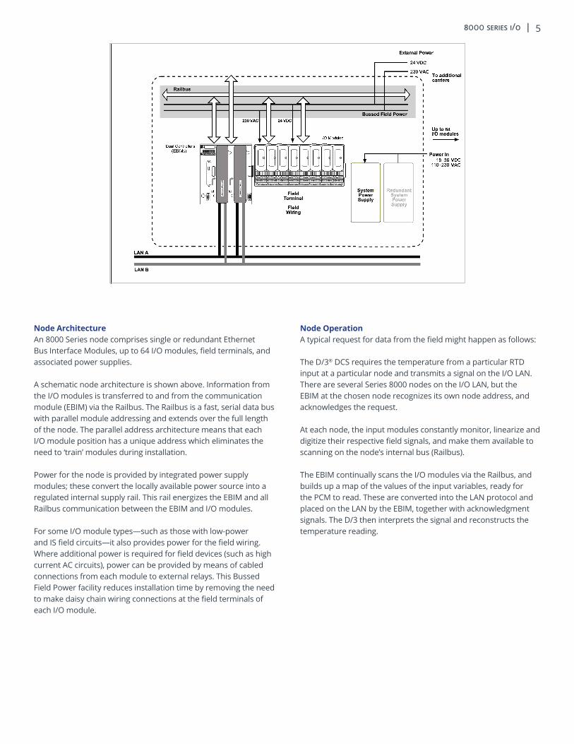
Node ArchitectureAn 8000 Series node comprises single or redundant Ethernet Bus Interface Modules, up to 64 I/O modules, field terminals, and associated power supplies.
A schematic node architecture is shown above. Information from the I/O modules is transferred to and from the communication module (EBIM) via the Railbus. The Railbus is a fast, serial data bus with parallel module addressing and extends over the full length of the node. The parallel address architecture means that each I/O module position has a unique address which eliminates the need to ‘train’ modules during installation.
Power for the node is provided by integrated power supply modules; these convert the locally available power source into a regulated internal supply rail. This rail energizes the EBIM and all Railbus communication between the EBIM and I/O modules.
For some I/O module types—such as those with low-power and IS field circuits—it also provides power for the field wiring. Where additional power is required for field devices (such as high current AC circuits), power can be provided by means of cabled connections from each module to external relays. This Bussed Field Power facility reduces installation time by removing the need to make daisy chain wiring connections at the field terminals of each I/O module.
Node OperationA typical request for data from the field might happen as follows:
The D/3® DCS requires the temperature from a particular RTD input at a particular node and transmits a signal on the I/O LAN. There are several Series 8000 nodes on the I/O LAN, but the EBIM at the chosen node recognizes its own node address, and acknowledges the request.
At each node, the input modules constantly monitor, linearize and digitize their respective field signals, and make them available to scanning on the node’s internal bus (Railbus).
The EBIM continually scans the I/O modules via the Railbus, and builds up a map of the values of the input variables, ready for the PCM to read. These are converted into the LAN protocol and placed on the LAN by the EBIM, together with acknowledgment signals. The D/3 then interprets the signal and reconstructs the temperature reading.

6 | novatech
ModulesI/O modules transfer signals to and from field instruments. Input modules receive signals from transmitters and sensors and convert them into a digital form for presentation to the EBIM. Output modules receive commands from the EBIM and transfer them to actuators. A wide range of modules is available, including types for low-level instrumentation, AC circuits, and intrinsically safe (IS) signals. I/O modules typically have 4, 8, 16, or 32 field channels.
CarriersCarriers allow the 8000 Series I/O to mount onto a flat panel or T- or G-section DIN rail. They support and interconnect the EBIM, power supplies, I/O modules and field terminals, and carry the address, data and power lines of the internal Railbus. They provide termination points for the LAN and field wiring cable shields and can also distribute bussed field power to the I/O modules. I/O module carriers support eight I/O modules.
Field Terminal AssembliesField terminal assemblies provide the interface between the I/O modules and the field wiring. They include fusing and loop disconnect as options. A mechanical keying system prevents an I/O module from being connected to the wrong type of field terminal. Field terminals mount onto the module carrier, one to each I/O module. They are clamped firmly by the I/O module to form an electrical and mechanical assembly of high integrity. They may be replaced in service without removing carriers or disturbing the operation of other modules.
Power Supplies8000 Series I/O power supplies accept locally available unregulated power and provide a regulated supply for the EBIM and I/O modules. Supply redundancy is supported. The system power supply at an 8000 Series node converts the local supply to power the node, and can also provide field power for I/O modules with low-level field circuits. Where heavy-current or AC mains circuits are handled by the I/O modules, the 8000 Series method for distributing field power avoids complex wiring at the field terminal and minimizes the backplane/carrier wiring.
NovaTech 8000 SeriesI/O Components

8000 series i/o | 7
Ethernet Bus Interface ModuleNovaTech 8000 Series I/O uses the Ethernet Bus Interface Module (EBIM) to provide a high speed Ethernet data connection to the D/3®. The EBIMs communicate using a proprietary protocol over Ethernet at speeds of 10/100MB to the D/3 PCMs.
NovaTech 8000 Series I/O Support8000 Series I/O offers a variety of I/O boards and signal conditioning termination panels suitable for virtually every standard process sensor and actuator. Details on signal conditioning termination panels, as well as their associated I/O function boards, can be obtained in individual specification sheets. The standard D/3 configuration supports such I/O signals as: • Analog Inputs: 4-20 mA, 0-1 V, 0-5 V, 0-10 V, 1-5 V, ±10 V, RTDs,
thermocouples • Analog Outputs: 4-20 mA
• Digital and Pulse Inputs: › Contact Closures +24 V dc › Contact Closures 115 V ac › Pulse Train Inputs up to 200 KHz @ +24 V dc
• Digital and Pulse Outputs: › DC Output 2 to 60 V dc › AC Output 20 to 265 V ac › Pulse Output 2 msec. to 130 sec @ 2 to 60 V dc › Pulse Output 2 msec. to 130 sec. @ 20 to 265 V ac
Systems Power12 V dc
Bussed Field Power24 V dc or 120 V ac

8 | novatech
NovaTech 8000 Series EBIMNT-8521-EB-NT
The NovaTech 8000 Series EBIM, NT-8521-EB-NT, is a rugged, field-mountable, D/3® 8000 I/O communications controller. Designed for process applications, redundant EBIMs provide dual redundant communications between the PCM and 8000 I/O modules for high system availability. Combined with field mounted 8000 Series I/O system components, it offers cost savings over control room mounted systems as well as flexible system design.
Key Features• Redundancy with bumpless transfer• Dual-redundant high-speed Ethernet connections• Field mountable in harsh process environments• On-line configuration and reconfiguration• HART® pass-through of process and status variables• Integrated general-purpose and intrinsically safe (IS) signals
On-line ChangesEBIMs allow on-line configuration changes. You can add or remove EBIMs, add or remove modules, activate or deactivate points, activate or deactivate HART, and change module and point parameters all online.
Built-in DiagnosticsExtended diagnostics are available to provide module and channel status information, including high and low alarm, open circuit detection, and line fault detection at the device level and “fail-safe” perform level.
Reduced Cable CostsInstrumentation cable pairs terminate locally instead of being run across the plant to the control room. Heavy, expensive sensor cables are replaced by the LAN cable.
High System Availability - Easy MaintenanceMaximize up-time through use of redundant EBIM controllers, power supplies, and network connections. “Hot swap” modules without affecting system operation or re-configuring even in hazardous areas.
EBIM RedundancyRedundant EBIMs can be used for critical control applications. The redundant EBIM pair operates in parallel, checking status multiple times through the processing loop enabling the backup EBIM to continuously monitor the health of the master EBIM, assuring a rapid and bumpless transfer to the standby EBIM.
Network RedundancyIn addition to EBIM redundancy, the EBIM has two high-speed Ethernet ports to provide security of communication. Each port can be connected to an independent LAN which is continuously monitored for its integrity. The fault tolerant network protocol provides network diagnostics and manages network connectivity. If the primary port detects a network failure, traffic is immediately switched to the other LAN to maintain full communication.
Failsafe and Automatic Cold StartIn the event of complete loss of communication the EBIM will adopt a user-defined failsafe mode and similarly instruct the I/O to take up user-defined failsafe values. In the event of power loss the EBIM will perform a cold restart.
I/O Module ConfigurationThe EBIM receives full details of all the I/O modules under its control and stores the information in non-volatile memory. At start-up the controller downloads to the modules their configuration details, which also include the failsafe states they should adopt in the event of communication failure.
Firmware UpdatesIn keeping with its ability to maintain operations on a continuous basis, redundant EBIMs are also capable of receiving a firmware upgrade. An EBIM can receive an update to its firmware while still in the field. When the upgrade has been confirmed as successful, the EBIM can be returned to full operation as a master or as a protective standby and the redundant EBIM’s firmware can then be upgraded.
8000 series i/o | 9
HART Pass-throughThe EBIM has the ability to pass smart HART® information from field devices to the D/3® PCM and to a separate PC workstation. The D/3 PCM can read the additional four HART process variables associated with each 4-20 mA signal and also the instrument alarm and warning statuses. Connecting the I/O switch to a PC workstation allows you to readily interface to asset management software applications, to remotely manage the HART information contained in your HART-based field instruments. The EBIM works with a variety of asset management packages, including Endress+Hauser’s FieldCare.
Hazardous Area OperationThe EBIM is designed also to operate in Class 1, Division 2, and Zone 2 hazardous areas and can control I/O modules that have field wiring extending into the more hazardous Division 1, Zone 1, and Zone 0 areas.
Grows As Your Needs GrowThe system is scalable to your needs. You can add modular I/O to your system as your needs increase. Redundant EBIMs can be added without the need to power off your system - the backup EBIM powers up automatically and is seamlessly brought online.
Environmental StabilityLike all of the 8000 Series equipment, the EBIM is designed for use in harsh environments. It operates over a temperature range of -40°C to +70°C and is resistant to shock, vibration, and corrosive environments.
Power SuppliesEach EBIM can be powered individually. NovaTech’s recommends using redundant or load sharing supplies to power the EBIMs. The EBIM carrier can also accommodate a Power Supply Monitor module (NT-8410-NS-PS), which monitors the health signals available from up to seven power supplies and reports problems to the D/3.
8000 with Intrinsically Safe Field WiringThe 8000 Series I/O System is also capable of supporting I/O modules with intrinsically safe (IS) field wiring, for connection to certified or ‘simple apparatus’ field devices in Division 1 or Zone 0 hazardous areas. A range of I/O module types with IS field circuits for industry-standard DI, DO, AI, AO, and pulse applications is supported.
Integrated Intrinsically Safe Power SuppliesPower for IS I/O modules is derived from integrated, modular power supply units. Each power unit is capable of supplying between eight and twenty I/O modules, depending on the I/O type and mix. Optional power supply redundancy is supported by means of an additional, redundant supply unit connected in an ‘n+1’ arrangement. In applications with mixed IS and non-IS safe field wiring, the full facilities of the ‘Bussed Field Power’ regime are retained for the non-IS part of the system. In nodes populated only with IS I/O modules, a separate system power supply module provides power for the Bus Interface Module and ‘node services’. Redundancy of this supply is also supported.
LAN InterfaceTransmission medium ....................100BaseTX or 10BaseT EthernetTransmission protocol ................Modbus over High Speed EthernetTransmission rates ...................................................... 10-100 Mbits/sLAN connector type (x2) ......................................................RJ45 (8-pin) LAN Insulation (Dielectric withstand) ........................................1500 VAction on software malfunction .........................Halt CPU/Reset CPUMax. nodes per EMPC2 .......................................................................50
Hazardous Area ApprovalsLocation of controller ............Zone 2, IIC T5 hazardous area .........orClass 1, Div 2, Groups A, B, C, D T5 hazardous locationApplicable standards:• Factory Mutual Research Co., Class No. 3611 for Class I,
Division 2, Groups A, B, C, D hazardous locations• CSA Std C22.2 No. 213 for Class 1, Division 2, Groups A, B, C, D
hazardous locations• ATEX Category 3 (for Zone 2 installation) to EN50021:1999
protection type ‘n’• UL 61010-1 “Safety Requirements for Electrical Equipment for
Measurement, Control, and Laboratory Use; Part 1: General Requirements, 2nd Edition
MechanicalModule dimensions ..............................69 (w) x 232 (d) x 138 (h) mmWeight (approx.) ..........................................................................1.35 kg
10 | novatech
NovaTech 8000 SeriesSystem Specifications
MechanicalMounting Method ............................................Flat panel or DIN-railDIN-rail types ..........................’Top hat’, 35 x 7.5 mm to EN 50022...............................................................or 35 x 15 mm to EN 50022...................................................................or G-section, to EN 50035
Railbus (Backplane)Maximum physical length* of node .....................................6.8 mmMaximum number of extender cables ............................................3*overall, including backplanes and extender cables
Node SizeBIM/Controller type Module limit
8521-EB-NT ....................................................................64 max.
Note: I/O module carriers used with these must conform to the same module address limits. See I/O module carrier datasheets for details.
ElectricalEMC compliance .............................................To BS EN 61326:1998Electrical safety ...............................................................EN 61010-1
IsolationI/O Modules - 2/2 Between isolated channels ..............250 V ac rms (to EN 61010-1).....................................................................(tested at 2.3 kV ac rms)Channel (any) to Railbus .............................................250 V ac rms(Except where stated on individual module specifications)
I/O Modules - 2/1 Between hazardous area terminals and Railbus ...........60 V ac rmsBetween IS field circuits of separate I/O modules† .....500 V ac rmsBetween any IS field circuit & non-IS field circuit ......250 V ac rms..........................................refer to individual module specifications† 60 second test
EnvironmentalAmbient tempOperating, optimum orientation* ..............................-40°C to +70°C(except where stated in individual module specifications)Operating, non-optimum orientation* ....................-40°C to +50°C(except where stated in individual module specifications)Storage ........................................................................-40°C to +85°C*Optimum orientation is when the carrier is mounted in a vertical plane with field terminals located below the modules
Relative humidity ..............................5 to 95% RH (non-condensing)
Ingress Protection ...................................IP20 to BS EN60529:1992(Additional protection by means of enclosure)
Corrosive atmospheres: Designed to meet ten year service in Class G3 corrosive environment, as defined by ISA Standard SP71.04.
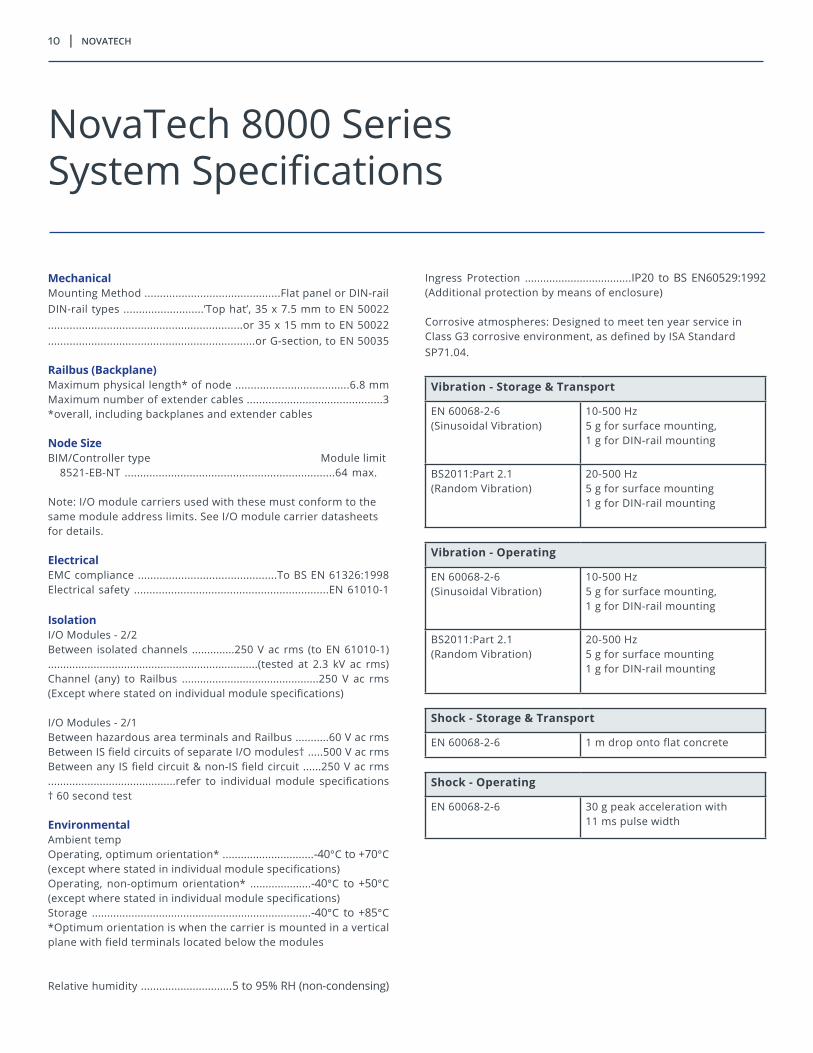
Vibration - Storage & Transport
EN 60068-2-6(Sinusoidal Vibration)
10-500 Hz5 g for surface mounting,1 g for DIN-rail mounting
BS2011:Part 2.1(Random Vibration)
20-500 Hz5 g for surface mounting1 g for DIN-rail mounting
Vibration - Operating
EN 60068-2-6(Sinusoidal Vibration)
10-500 Hz5 g for surface mounting,1 g for DIN-rail mounting
BS2011:Part 2.1(Random Vibration)
20-500 Hz5 g for surface mounting1 g for DIN-rail mounting
Shock - Storage & Transport
EN 60068-2-6 1 m drop onto flat concrete
Shock - Operating
EN 60068-2-6 30 g peak acceleration with11 ms pulse width

8000 series i/o | 11
Hazardous Area Approvals - 2/2 Node8000 node equipment location* .................................Safe area or..................................................... Zone 2, IIC T4 hazardous area or......................... Class 1, Div 2, Groups A-D, T4 hazardous location*except for 8101-HI-TX, 8103-AI-TX, and 8119-VI-05.......................................................................................... Safe area or Zone 2, IICT4 (Tamb = 60° C), T3 (Tamb = 70°C) hazardous area or............................................. Class 1, Div 2, Groups A-D, (Tamb = 60° C)...................................................... (Tamb = 60° C) hazardous location
Field equipment and wiring location.......................................................................................... Safe area or ..................................................... Zone 2, IIC T4 hazardous area or................................ Class 1, Div 2, Groups A-D hazardous location(Temperature classification will be determined by thefield apparatus)
Hazardous Area Approvals - 2/1 Node8000 node equipment location* .................................Safe area or..................................................... Zone 2, IIC T4 hazardous area or......................... Class 1, Div 2, Groups A-D, T4 hazardous location
Field equipment and wiring location............................................................ Zone 0, IIC hazardous area or................................ Class 1, Div 2, Groups A-D hazardous location(Temperature classification will be determined by thefield apparatus)
Application standards:• Factory Mutual Research Co., Class No. 3611 for Class I, Division 2,
Groups A, B, C, D hazardous locations• Factory Mutual Research Co., Class No. 3610 for Class I, II, III,
Division 1, 2 Groups A-G hazardous locations• EN 50014:1992 Electrical apparatus for potentially explosive
atmospheres, general requirements• EN 50020:1995 Electrical apparatus for potentially explosive
atmospheres, intrinsically safe “i”• EN 50021:1999 Electrical apparatus for potentially explosive
atmospheres, type of protection “n”• EC Directive 94/9/EC (ATEX 100A)
Local Area NetworkFieldbus protocols supported .........................Modbus (RTU mode).......................................................................................... Profibus - DP
Note:1. Protocols are selected by choice of Bus Interface Module2. For other protocols consult NovaTech
Configuration:1) via host LAN (if supported by LAN)2) via PC connected locally at configuration port
Node address setting ..........................Software settable in the BIMLAN physical medium (configurable on carrier) ................................LAN A ............................................................RS485 or RS422, 5-wireLAN B (where available) ..............................RS485 or RS422, 5-wireLAN isolationLAN A to B (if applicable) ........................................................250 V acLAN A or B to system ground .........................250 V ac (to EN 61010)
Local Area NetworkSystem SupplyLocal supply input ................................................18.5-36 V dc inputSupply redundancy ............................................................supportedRailbus supply voltage ...................................................12 V dc ± 5%
12 | novatech
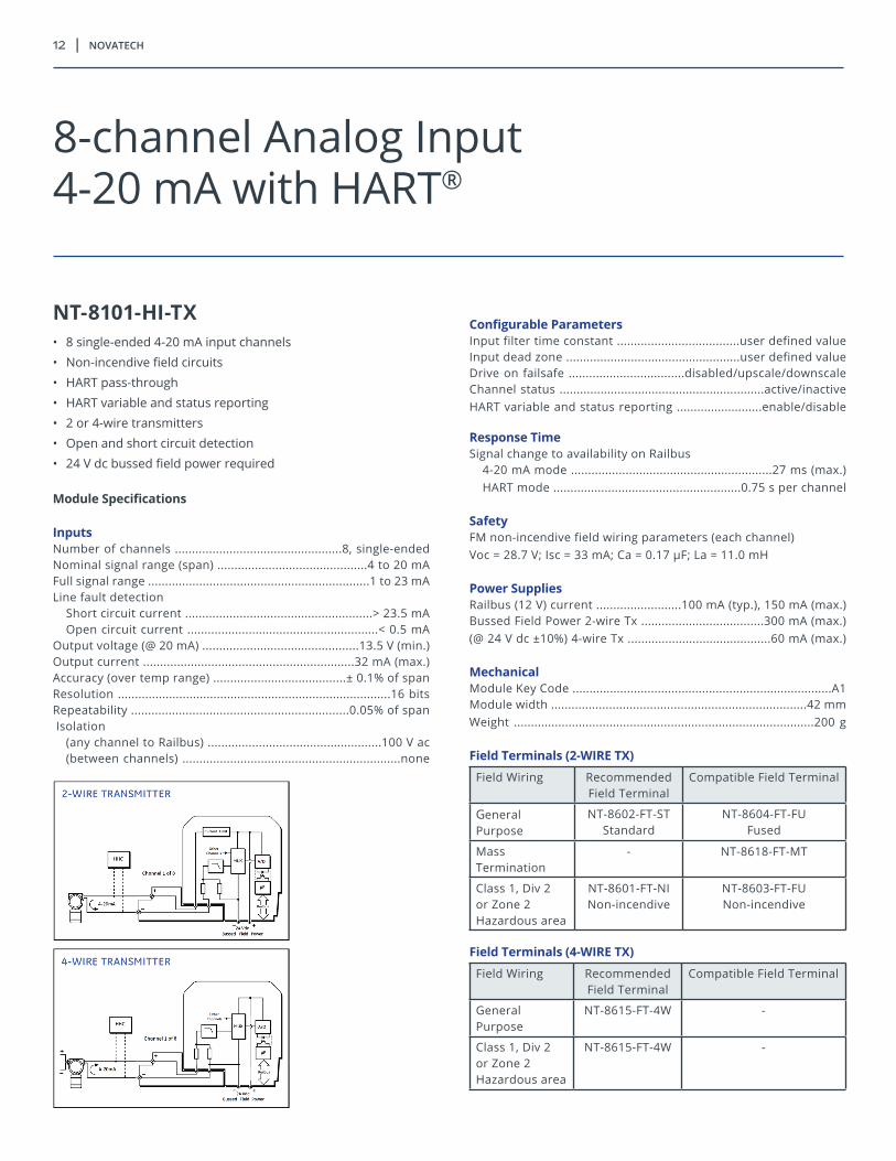
NT-8101-HI-TX• 8 single-ended 4-20 mA input channels • Non-incendive field circuits • HART pass-through • HART variable and status reporting • 2 or 4-wire transmitters • Open and short circuit detection • 24 V dc bussed field power required
Module Specifications
Inputs Number of channels .................................................8, single-ended Nominal signal range (span) ............................................4 to 20 mA Full signal range .................................................................1 to 23 mALine fault detection
Short circuit current .......................................................> 23.5 mAOpen circuit current ........................................................< 0.5 mA
Output voltage (@ 20 mA) ..............................................13.5 V (min.)Output current ..............................................................32 mA (max.)Accuracy (over temp range) .......................................± 0.1% of spanResolution ................................................................................16 bitsRepeatability ................................................................0.05% of span Isolation
(any channel to Railbus) ...................................................100 V ac(between channels) ................................................................none
Configurable ParametersInput filter time constant ....................................user defined valueInput dead zone ...................................................user defined valueDrive on failsafe ..................................disabled/upscale/downscaleChannel status ............................................................active/inactiveHART variable and status reporting .........................enable/disable
Response TimeSignal change to availability on Railbus
4-20 mA mode ...........................................................27 ms (max.)HART mode .......................................................0.75 s per channel
SafetyFM non-incendive field wiring parameters (each channel) Voc = 28.7 V; Isc = 33 mA; Ca = 0.17 µF; La = 11.0 mH
Power SuppliesRailbus (12 V) current .........................100 mA (typ.), 150 mA (max.)Bussed Field Power 2-wire Tx ....................................300 mA (max.) (@ 24 V dc ±10%) 4-wire Tx ..........................................60 mA (max.)
MechanicalModule Key Code ............................................................................A1 Module width ...........................................................................42 mm Weight ........................................................................................200 g
Field Terminals (2-WIRE TX)
Field Wiring Recommended Field Terminal
Compatible Field Terminal
General Purpose
NT-8602-FT-STStandard
NT-8604-FT-FU Fused
Mass Termination
- NT-8618-FT-MT
Class 1, Div 2 or Zone 2 Hazardous area
NT-8601-FT-NI Non-incendive
NT-8603-FT-FUNon-incendive
Field Terminals (4-WIRE TX)
Field Wiring Recommended Field Terminal
Compatible Field Terminal
General Purpose
NT-8615-FT-4W -
Class 1, Div 2 or Zone 2 Hazardous area
NT-8615-FT-4W -
8-channel Analog Input4-20 mA with HART®

8000 series i/o | 13
NT-8103-AI-TX• 8 single-ended 4-20 mA input channels• Non-incentive field circuits• 4-20 mA • 2 or 4-wire transmitters • Open and short circuit detection• 24 V dc bussed field power required
Module Specifications
Inputs Number of channels .................................................8, single-endedNominal signal range (span) ............................................4 to 20 mAFull signal range ...............................................................1 to 23 mA Out of range alarm
Lower threshold .............................................................> 23.5 mAUpper threshold ...............................................................< 0.5 mA
Output voltage (@ 20 mA) .............................................13.5 V (min.)Output current .............................................................32 mA (max.)Accuracy (over temp range) ......................................± 0.1% of span
Resolution ................................................................................16 bitsRepeatability ...............................................................0.05% of spanIsolation
(any channel to Railbus) ...................................................100 V ac(between channels) ................................................................none
Configurable ParametersInput filter time constant ....................................user defined valueInput dead zone ..................................................user defined valueDrive on failsafe ....................................disabled/upscale/downscaleChannel status ............................................................active/inactive
Response TimeSignal change to availability on Railbus .......................27 ms (max.)
SafetyFM non-incendive field wiring parameters (each channel) ......................Voc = 28.7 V; Isc = 33 mA; Ca = 0.17 µF; La = 11.0 mH
Power SuppliesRailbus (12 V) current ..........................100 mA (typ.)/150 mA (max.)Bussed Field Power ....................................2-wire Tx 300 mA (max.)(@ 24 V dc ± 10%) 4-wire Tx 60 mA (max.)
MechanicalModule Key Code ...........................................................................A1Module width ..........................................................................42 mmWeight ........................................................................................200 g
Field Terminals (2-wire TX)
Field Wiring Recommended Field Terminal
Compatible Field Terminal
General Purpose
NT-8602-FT-STStandard
NT-8604-FT-FUFused
Mass Termination
- NT-8618-FT-MT
Class 1, Div 2 or Zone 2 Hazardous area
NT-8601-FT-NINon-incendive
NT-8603-FT-FUNon-incendive Fused
Field Terminals (4-wire TX)
Field Wiring Recommended Field Terminal
Compatible Field Terminal
General Purpose
NT-8615-FT-4W -
8-channel Analog Input4-20 mA
14 | novatech
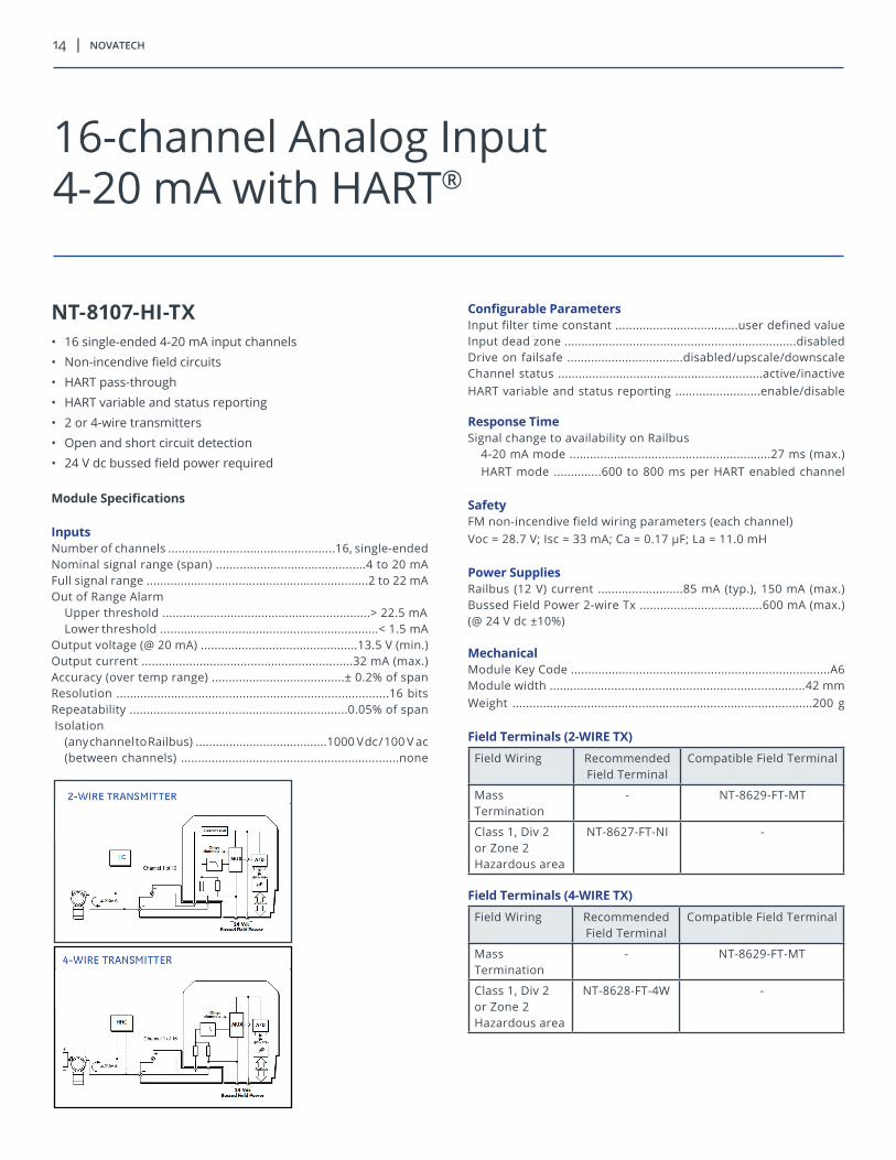
NT-8107-HI-TX• 16 single-ended 4-20 mA input channels • Non-incendive field circuits • HART pass-through • HART variable and status reporting • 2 or 4-wire transmitters • Open and short circuit detection • 24 V dc bussed field power required
Module Specifications
Inputs Number of channels .................................................16, single-ended Nominal signal range (span) ............................................4 to 20 mA Full signal range .................................................................2 to 22 mAOut of Range Alarm
Upper threshold .............................................................> 22.5 mALower threshold ................................................................< 1.5 mA
Output voltage (@ 20 mA) ..............................................13.5 V (min.)Output current ..............................................................32 mA (max.)Accuracy (over temp range) .......................................± 0.2% of spanResolution ................................................................................16 bitsRepeatability ................................................................0.05% of span Isolation
(any channel to Railbus) .......................................1000 V dc / 100 V ac(between channels) ................................................................none
Configurable ParametersInput filter time constant ....................................user defined valueInput dead zone ....................................................................disabled Drive on failsafe ..................................disabled/upscale/downscaleChannel status ............................................................active/inactiveHART variable and status reporting .........................enable/disable
Response TimeSignal change to availability on Railbus
4-20 mA mode ...........................................................27 ms (max.)HART mode ..............600 to 800 ms per HART enabled channel
SafetyFM non-incendive field wiring parameters (each channel) Voc = 28.7 V; Isc = 33 mA; Ca = 0.17 µF; La = 11.0 mH
Power SuppliesRailbus (12 V) current .........................85 mA (typ.), 150 mA (max.)Bussed Field Power 2-wire Tx ....................................600 mA (max.) (@ 24 V dc ±10%)
MechanicalModule Key Code ............................................................................A6 Module width ...........................................................................42 mm Weight ........................................................................................200 g
Field Terminals (2-WIRE TX)
Field Wiring Recommended Field Terminal
Compatible Field Terminal
Mass Termination
- NT-8629-FT-MT
Class 1, Div 2 or Zone 2 Hazardous area
NT-8627-FT-NI
-
Field Terminals (4-WIRE TX)
Field Wiring Recommended Field Terminal
Compatible Field Terminal
Mass Termination
- NT-8629-FT-MT
Class 1, Div 2 or Zone 2 Hazardous area
NT-8628-FT-4W -
16-channel Analog Input4-20 mA with HART®

8000 series i/o | 15
NT-8132-AI-UN• 8 isolated, universal, input channels• Configurable on a channel by channel basis:
4-20 mA, THC, RTD, resistance, and voltage• 250 V ac rms channel to channel isolation• Thermocouple types B, E, J, K, N, R, S, and T• RTD types Pt100, jPt100, Pt200, Pt500, Ni120, Cu10• Volt input types ± 120 mV, 0-1 V, 0-5 V, 1-5 V, 0-10 V, ± 10 V• 2 or 3-wire RTDs• 2 or 4-wire transmitters• Non-incendive field circuits• 24 V dc bussed field power required
Module Specifications
Inputs Number of configurable channels ....................................8 isolated
4-20mA InputsNominal signal range (span) .............................................4 to 20 mAFull signal range (FSR) .......................................................0 to 25 mAOutput voltage (@ 20mA) ..............................................13.5 V (min.)Output current (linear operation) ...............................25 mA (max.)Short circuit current (max.) ...................................75 mA for 100 ms(Output turns off after ~100 ms at more than 25 mA)Calibration accuracy
10°C to 40°C .............................................................± 0.1% of FSR–40°C to 70°C ............................................................± 0.3% of FSR
Resolution ......................................................................15 bits (typ.)Repeatability ...............................................................0.05% of span
Thermocouple InputsTHC Types ......................................................B, E, J, K, N, R, S, and TCalibration Accuracy
10°C to 40°C .................................................± 0.1% of span (typ.)-40°C to 70°C ...............................................± 0.2% of span (typ.)
Cold junction compensation error †< ± 1°C (-40°C to +70°C)Resolution ......................................................................14 bits (typ.)Optional open circuit bleed current .........................± 1.2uA (nom.)Open circuit detection time .......................................................1 sec........................................................(with < 0.5 µF cable capacitance)
RTD Input (2 or 3 Wire)RTD types .........................Pt100, Pt200, Pt500, Cu10, Ni120; jPt100Maximum wire resistance ...................................................40 ohmsCalibration accuracy 3-wire
10°C to 40°C ...........................................................± 0.1% of span-40°C to 70°C .........................................................± 0.2% of span
RTD excitation current .........................selected for ~0.2 mW at 0°CResolution ......................................................................14 bits (typ.)Open circuit detection time .......................................................1 sec........................................................(with < 0.5 µF cable capacitance)
Resistance Input (2 or 3 Wire)Input resistance range (span) .....................................0 to 110, 280,.............................................................................470 and 1000 ohmsCalibration accuracy 3-wire
10°C to 40°C ...........................................................± 0.2% of span-40°C to 70°C .........................................................± 0.4% of span
Maximum wire resistance ...................................................40 ohmsResistance excitation current .........selected for ~1.0 mW at max RResolution ......................................................................14 bits (typ.)
† C J compensation located in recommended field terminal
8-channel Isolated Universal Analog Input4-20 mA with Thermocouple, RTD, Voltage

16 | novatech
Voltage InputNominal signal range 1 (span) ................................± 120 mV, 0-1 V,......................................................................0-5 V, 1-5 V, 0-10 V, ± 10 VResolution ......................................................................14 bits (typ.)
Configurable ParametersSensor type ................................................................user selectableInput dead zone ..................................................user defined valueChannel status ...........................................................active/inactiveFilter/sample rates ....................................................user selectable
General SpecificationsCommon mode rejection (using 50/60 Hz filter) ..........................................................................................................> 120 dB @ 50/60 HzSeries mode rejection (using 50/60 Hz filter) .................................................................................................................> 65 dB @ 50/60 HzMaximum input voltage (except current I/P) ..........................± 25 VCommon mode voltage between channels .................250 V ac rmsIsolation
(channel to channel) .................................................250 V ac rms(any channel to Railbus) ...........................................250 V ac rms(any channel to Bussed Field Power) .......................250 V ac rms(Railbus to Bussed Field Power) ...............................150 V ac rms
Input filter frequency response .........................time constant 4 msInput impedance ...............................................................> 1 M ohmData Format ....................0 to 66535 corresponds to selected spanOpen circuit detection ............................................................< 1 sec........................................................(with < 0.5 µF cable capacitance)
SafetyFM non-incendive field wiring parameters (each channel).............................Voc = 20 V; Isc = 75 mA; Ca = 0.61 µF; La = 11.3 mH
Power SuppliesRailbus (12 V) current ......................................................60 mA (typ.)......................................................................................125 mA (max.)Bussed Field Power @ 24 V dc ± 10%All configurations - except 4-20 mA with excitation ...125 mA (max.)4/20 mA with excitation ..............................................300 mA (max.)
MechanicalModule Key Code .........................................................................A1*Module width ...........................................................................42 mmWeight .........................................................................................185 g
* WARNING: If this module is being used in an application that requires 250 V ac rms channel-to-channel isolation, it must be replaced only with an A1 key code module that has equivalent, or better, channel-to-channel isolation rating.
Field Terminals
Field Wiring Recommended Field Terminal
Compatible Field Terminal
All Purpose NT-8608-FT-NI (no internal CJ)
8607-FT-TC (see note) (internal CJ)
4-20 mA, MassTermination
- NT-8618-FT-MT
RTD, VoltageMass Termination
- NT-8619-FT-MT
THC NT-8607-FT-TC (internal CJ)
8608-FT-NI (see note) (no internal CJ)
NOTE: For further advice on field terminals for this module and for operations with more than one type of sensor, see NovaTech 8000 I/O Hardware User’s Guide

8000 series i/o | 17
NT-8105-TI-TC• 4 thermocouple or mV* input channels• Cold junction compensation
Module Specifications
Inputs Number of channels .........................................................................4THCs types ..........................B,E,J,K,N,R,S, or T to EN 60584-2, IEC584-2, BS4937
Input Ranges
Input Type Range
mV 0 to 120 mV
Thermocouples: B 0°C to 1820°C
E -270°C to +1000°C
J -210°C to +1200°C
K & N -270°C to +1372°C
R & S -50°C to + 1768°C
T -270°C to + 400°C
Calibration Accuracy mV input .......................................± 0.2% of span (-40°C to +70°C)
.....................................................± 0.1% of span (+10°C to +40°C)THC input ...............................dependent on thermocouple typeCold junction compensation error† .....< ± 1°C (-40°C to +70°C)
Resolution ..........................................................15 bits plus sign bitCommon mode rejection ...................................> 80 dB @ 50/60 Hz Series mode rejection ........................................> 40 dB @ 50/60 Hz Maximum input voltage ..........................................................± 4.0 VCommon mode voltage between channels ................± 4.5 V (max.) Isolation (any channel to Railbus) ................................250 V ac rms Open circuit bleed current .......................................± 0.5 µA (nom.)
Configurable ParametersSensor type ................................................................user selectable Input dead zone (hysteresis) ..............................user defined value Selectable input filtering ...........off/2 reading avge./running avge. Drive on open circuit fault ............... disabled/upscale/downscale Channel status ............................................................active/inactive
Response TimesSignal change to availability on Railbus .......................................................................................120 ms (min.)......................................................................................420 ms (max.)O/C sensor detection ................................................................≤ 10 s
SafetyFM non-incendive field wiring parameters (each channel)....................Voc = 10.5 V; Isc = 3.6 mA; Ca = 14.9 µF; La = 1000 mH
Power SuppliesRailbus (12 V) current ....................................................150 mA (typ.)......................................................................................200 mA (max.)Bussed Field Power .......................................................not required
MechanicalModule Key Code ...........................................................................C1Module width ..........................................................................42 mmWeight ........................................................................................200 g
Field Terminals
Field Wiring Recommended Field Terminal
Compatible Field Terminal
General Purpose
NT-8605-FT-TC THC
-
Class 1, Div 2 or Zone 2 Hazardous area
NT-8605-FT-TC THC
-
4-channel Analog InputThermocouple and mV

18 | novatech
NT-8106-TI-RT• 4 RTD or resistance* source inputs• Function defined by configuration• 2, 3, or 4-wire RTD types accommodated
Module Specifications
Inputs Number of channels .........................................................................4 RTD input (2, 3, or 4 wire).....................................................Pt100 to BS1904/DIN43760/IEC 75........................................................Ni120; jPt100 to JIS C1604: 1989
Input Ranges
Input Type Range
Resistance Consult NovaTech for availability
RTDs: Pt100 -200°C to +850°C
jPt100 -200°C to +510°C
Ni120 -60°C to +320°C
Input resistance range (span) ...........................................0 to 500 Ω
Accuracy (% of span)
Tamb (RTD & Ω inputs)
25°C ± 0.05%
+10°C to +40°C ± 0.1%
-40°C to +70°C ± 0.2%
RTD excitation current ................................................200 μA (nom.)Resolution ..........................................................15 bits plus sign bit
Common mode rejection ...................................> 80 dB @ 50/60 HzSeries mode rejection ........................................> 40 dB @ 50/60 HzIsolation (any channel to Railbus) ................................250 V ac rmsOpen circuit bleed current ..........................................0.5 μA (nom.)
Configurable ParametersSensor type ..................................................................user selectionInput deadzone ...................................................user defined valueSelectable input filtering ...........off/2-reading avge/running avge.Drive on open circuit fault ................................... disabled/upscaleChannel status ...........................................................active/inactiveOffset (2-wire RTD mode) ...................................user defined value
Response TimesSignal change to availability on Railbus .......................................................................................180 ms (min.)......................................................................................840 ms (max.)O/C sensor detection ................................................................≤ 10 s
SafetyFM non-incendive field wiring parameters (each channel) ....................Voc = 10.5 V; Isc = 3.6 mA; Ca = 14.9 µF; La = 1000 mH
Power SuppliesRailbus (12 V) current ...................................................150 mA (typ.)......................................................................................200 mA (max.)Bussed Field Power .......................................................not required
MechanicalModule Key Code ...........................................................................C1Module width ..........................................................................42 mmWeight ........................................................................................200 g
Field Terminals
Field Wiring Recommended Field Terminal
Compatible Field Terminal
General Purpose
NT-8606-FT-RT RTD
-
Class 1, Div 2 or Zone 2 Hazardous area
NT-8606-FT-RT RTD
-
*Consult NovaTech for availability.
4-channel Analog InputRTD and Ω

8000 series i/o | 19
NT-8102-HO-IP
• 8 single-ended 4-20 mA output channels • Non-incendive field circuits • HART pass-through • HART variable and status reporting • Valve positioners and remote indicators, etc. • Open circuit detection on each channel • 24 V dc bussed field power required
Module Specifications
Inputs Number of channels .................................................8, single-endedNominal signal range (span) ............................................4 to 20 mAFull signal range ...............................................................1 to 23 mAOpen loop detection threshold ..................................0.7 ± 0.25 mAOutput compliance ..................................20 mA at 21.6 V dc supply..................................................................................(into 700 Ω load)Accuracy (over temp range) ....................................± 0.25% of spanResolution ................................................................................12 bitsIsolation
(any channel to Railbus) ...................................................100 V ac(between channels).................................................................none
Configurable ParametersInitialization state ..................................................predefined valueDrive on fail-safe ...................................predefined value/last valueChannel status .......................................................... active/inactiveHART variable and status reporting .........................enable/disable
Response TimeSignal change to availability on Railbus
4-20 mA mode ...........................................................25 ms (max.)HART mode.........................................................0.75 s per channel
SafetyFM non-incendive field wiring parameters (each channel) ......................Voc = 28.7 V; Isc = 33 mA; Ca = 0.17 µF; La = 11.0 mH
Power SuppliesRailbus (12 V) current ....................................................100 mA (typ.)......................................................................................150 mA (max.)Bussed Field Power ........................ 300 mA (max.) at 24 V dc ± 10%
MechanicalModule Key Code ...........................................................................A4Module width ..........................................................................42 mmWeight ........................................................................................200 g Field Terminals
Field Wiring Recommended Field Terminal
Compatible Field Terminal
General Purpose
NT-8602-FT-ST Standard
NT-8604-FT-FU Fused
Mass Termination
- NT-8618-FT-MT
Class 1, Div 2 or Zone 2 Hazardous area
NT-8601-FT-NI Non-incendive
NT-8603-FT-FU Non-incendive
8-channel Analog Output4-20 mA with HART®

20 | novatech
NT-8104-AO-IP• 8 single-ended outputs• 4–20 mA• For I/P converters and remote indicators, etc• Open circuit detection is provided on each channel• 24 V dc bussed field power required
Module Specifications
OutputsNumber of channels .................................................8, single-endedNominal signal range (span) ............................................4 to 20 mAFull signal output range ...................................................1 to 23 mAOpen loop detection threshold ..................................0.7 ± 0.25 mAOutput compliance......................................20 mA at 21.6 V dc supply (into 700 Ω load)Accuracy (over temp range) ....................................± 0.25% of spanOutput ripple ...........................................................< 0.02% of spanResolution ................................................................................12 bitsIsolation
any channel to Railbus .....................................................100 V ac
Configurable ParametersInitialization state...................................................predefined valueDrive on fail-safe .................................predefined value/last valueChannel status .................;.........................................active/inactive
Response TimeFrom Railbus command to output change ..................25 ms (max.)
SafetyFM non-incendive field wiring parameters (each channel)......................Voc = 28.7 V; Isc = 33 mA; Ca = 0.17 μF; La = 11.0 mH
Power SuppliesRailbus (12 V) current ...................................................100 mA (typ.)......................................................................................150 mA (max.)Bussed Field Power..........................300 mA (max.) @ 24 V dc ±10%Quiescent current ....................................................................60 mA
MechanicalModule Key Code ...........................................................................A4Module width ..........................................................................42 mmWeight ........................................................................................200 g
Field Terminals
Field Wiring Recommended Field Terminal
Compatible Field Terminal
General Purpose NT-8602-FT-STStandard
NT-8604-FT-FUFused
Mass Termination
- NT-8618-FT-MT
Class 1, Div 2 or Zone 2 Hazardous area
NT-8601-FT-NINon-incendive
NT-8603-FT-FUNon-incendive Fused
8-channel Analog Output4-20 mA

8000 series i/o | 21
NT-8109-DI-DC• 8 discrete isolated inputs• 24 V dc field voltage sources• User definable input threshold• Pulse counting option
Module Specifications
InputsNumber of channels .........................................................................8OFF voltage..........................................................................< 3.2 V dcON voltage ...........................................................................> 11 V dcWetting current ..........................................6.3 mA (nom.) @ 24 V dcMinimum pulse width detected .................................................3 msMaximum switching frequency (no-filtering) ........................200 HzMaximum voltage
Input ....................................................................................30 V dcReverse input ...................................................................– 25 V dc
Configurable ParametersSelectable input filter ...............................fast, slow or user defined(User defined permits 0 to 512 ms values in 2 ms steps)Latch inputs ...............................................................enable/disableLatch polarity ..........................................latch on high/latch on lowPulse counting ...........................................................enable/disable
Response TimeI/O response timeField event to new data available on Railbus ................3 ms (max.)
SafetyFM non-incendive field wiring parameters (each channel)............................Vmax = 30 V; Imax = 100 mA; Ci = 0 μF; Li = 0 mH
Power SuppliesRailbus (12 V) current ..................,...................................35 mA (typ.)........................................................................................55 mA (max.)Bussed Field Power .......................................................not required
MechanicalModule Key Code ...........................................................................B2Module width ..........................................................................42 mmWeight ........................................................................................170 g
Field Terminals
Field Wiring Recommended Field Terminal
Compatible Field Terminal
General Purpose NT-8602-FT-STStandard †
NT-8604-FT-FUFused
Mass Termination
- NT-8618-FT-MT
Class 1, Div 2 or Zone 2 Hazardous area
NT-8610-FT-NANon-arcing †
NT-8611-FT-FUNon-arcing,
Fused
† External fusing of the Field Power supply is recommended in order to protect the field wiring.
8-channel Discrete Input24 V dc, Isolated, Sinking

22 | novatech
NT-8110-DI-DC• 8 discrete inputs for dry contact switches• 24 V dc provided on input high side • Returns commoned internally• Pulse counting option• 24 V dc bussed field power required
Module Specifications
InputsNumber of channels ........................................................................8OFF current ........................................................................< 0.69 mAON current .........................................................................> 2.24 mAWetting current ................................................................5 mA (typ.)Minimum pulse width detected ................................................3 msMaximum switching frequency (no-filtering) ........................200 HzIsolation (any channel to Railbus) .......................................250 V ac
Configurable ParametersSelectable input filter ..............................fast, slow, or user defined
(User defined permits 0 to 512 ms values in 2ms steps)Latch inputs................................................................enable/disableLatch polarity..........................................latch on high/latch on lowPulse counting ...........................................................enable/disable
Response TimeI/O response timeField event to new data available on Railbus.................3 ms (max.) SafetyFM non-incendive field wiring parameters (each channel).......................Voc = 30 V; Isc = 15.2 mA; Ca = 0.12 μF; La = 151 mH
Power SuppliesRailbus (12 V) current.......................................................35 mA (typ.)........................................................................................55 mA (max.)Bussed Field Power ........................................40 mA, @ 18–36 V dc
MechanicalModule Key Code ...........................................................................B1Module width ..........................................................................42 mmWeight ........................................................................................170 g
Field Terminals
Field Wiring Recommended Field Terminal
Compatible Field Terminal
General Purpose
NT-8602-FT-ST Standard †
NT-8604-FT-FU
Mass Termination
- NT-8619-FT-MT
Class 1, Div 2 or Zone 2 Hazardous area
NT-8601-FT-NINon-incendive †
NT-8603-FT-FUNon-incendive, fused
† External fusing of the field power supply is recommended in order to protect the field wiring.
8-channel Discrete Input24 V dc, Non-isolated, Module Powered

8000 series i/o | 23
NT-8121-DI-DC• 16 input channels for dry contact switches• 24 V dc provided on input high side • Returns commoned internally• Pulse counting option• 24 V dc bussed field power required
Module Specifications
InputsNumber of channels .......................................................................16OFF current ..........................................................................< 0.3 mAON current ...........................................................................> 1.2 mAWetting current .............................................................2.8 mA (typ.)Minimum pulse width detected .................................................5 msMax input freq in pulse counting mode (no-debounce) .......100 HzIsolation (any channel to Railbus) .......................................250 V ac
Configurable ParametersSelectable input filter ..............................fast, slow or user defined
(User defined permits 0 to 512 ms values in 2ms steps)Latch inputs.................................................................enable/disableLatch polarity...........................................latch on high/latch on lowPulse counting ............................................................enable/disable
Response TimeI/O response timeField event to new data available on Railbus.................5 ms (max.) SafetyFM non-incendive field wiring parameters (each channel).......................Voc = 30 V; Isc = 3.5 mA; Ca = 0.12 μF; La = 1000 mH
Power SuppliesRailbus (12 V) current .....................................................90 mA (typ.)......................................................................................135 mA (max.)Bussed Field Power ..........................................60 mA, @ 18–30 V dc
MechanicalModule Key Code ...........................................................................E1Module width ..........................................................................42 mmWeight ........................................................................................210 g
Field Terminals
Field Wiring Recommended Field Terminal
Compatible Field Terminal
General Purpose
NT-8617-FT-NI16 channel DI
-
Mass Termination
- NT-8619-FT-MT
Class 1, Div 2 or Zone 2 Hazardous area
NT-8617-FT-NI16 channel DI
-
16-channel Discrete Input24 V dc, Non-isolated, Module Powered
24 | novatech
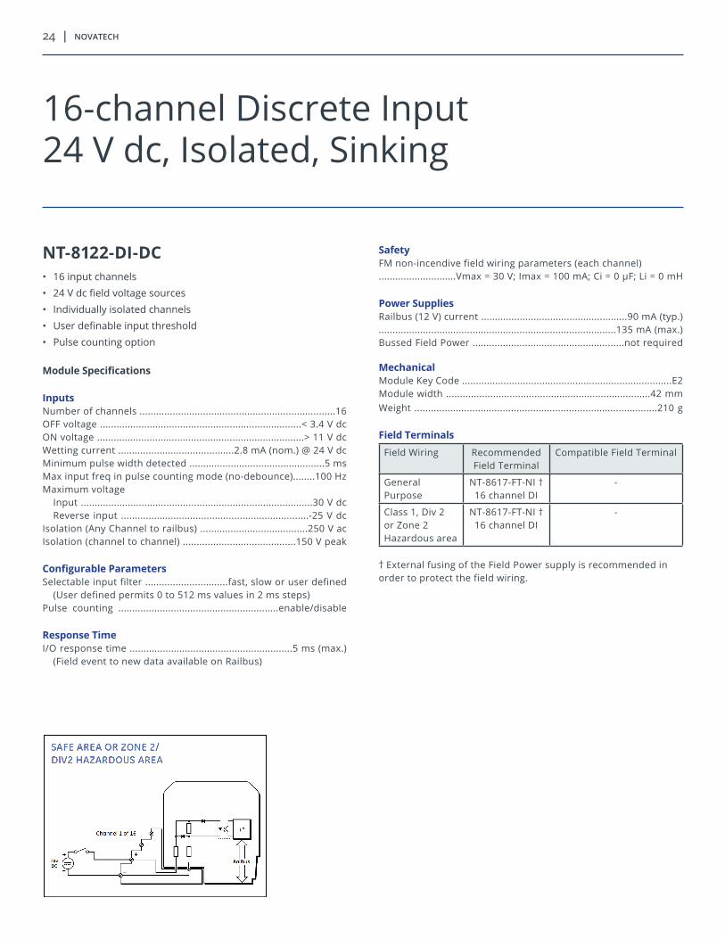
NT-8122-DI-DC• 16 input channels • 24 V dc field voltage sources • Individually isolated channels • User definable input threshold • Pulse counting option
Module Specifications
Inputs Number of channels .......................................................................16 OFF voltage .........................................................................< 3.4 V dc ON voltage ...........................................................................> 11 V dc Wetting current ..........................................2.8 mA (nom.) @ 24 V dc Minimum pulse width detected .................................................5 ms Max input freq in pulse counting mode (no-debounce)........100 HzMaximum voltage
Input ....................................................................................30 V dcReverse input ....................................................................-25 V dc
Isolation (Any Channel to railbus) .......................................250 V acIsolation (channel to channel) .........................................150 V peak
Configurable ParametersSelectable input filter ..............................fast, slow or user defined
(User defined permits 0 to 512 ms values in 2 ms steps) Pulse counting ..........................................................enable/disable
Response TimeI/O response time ...........................................................5 ms (max.)
(Field event to new data available on Railbus)
SafetyFM non-incendive field wiring parameters (each channel)............................Vmax = 30 V; Imax = 100 mA; Ci = 0 µF; Li = 0 mH
Power SuppliesRailbus (12 V) current .....................................................90 mA (typ.)......................................................................................135 mA (max.)Bussed Field Power .......................................................not required
MechanicalModule Key Code ............................................................................E2Module width ..........................................................................42 mmWeight ........................................................................................210 g
Field Terminals
Field Wiring Recommended Field Terminal
Compatible Field Terminal
General Purpose
NT-8617-FT-NI †16 channel DI
-
Class 1, Div 2 or Zone 2 Hazardous area
NT-8617-FT-NI †16 channel DI
-
† External fusing of the Field Power supply is recommended in order to protect the field wiring.
16-channel Discrete Input24 V dc, Isolated, Sinking

8000 series i/o | 25
NT-8125-DI-DC• 32 input channels • For dry contact switches or proximity detectors• Pulse counting and latching option• 24 V dc bussed field power required• Line fault detection on all inputs (switch inputs need resistors)
Module Specifications
Inputs Number of channels .......................................................................32OFF voltage .........................................................................< 1.2 mA ON voltage ...........................................................................> 2.1 mAShort circuit current .....................................................8.6 mA (typ)Output resistance ...........................................................950 Ω (typ)Open circuit output voltage ......................................8.2 V dc (typ)Line fault detection
Short circuit ........................................................................< 100 ΩOpen circuit ...........................................................................50 μA
Input voltage range without damage ..........................0 to + 12 V dcInput sampling rate (all 32) .....................................................8 kHzInput pulse width ............................................................250 μS (min)DI counting frequency without loss ..........................500 Hz (max) Applicable specification ...................................NAMUR, DIN 19234
Configurable ParametersInput filter ....................................0 to 8.192 secs in 250 μS stepsPulse counting .........................................................................on/offLatching ....................................................................................on/off
Response TimeInput module scan time ..........................................................< 1 ms(Inputs sampled at 8 kHz and processed every 1 mS)
SafetyFM non-incendive field wiring parameters (each channel).................Voc ≤ 8.64 V; lsc ≤ 18.5 mA; Ca ≤ 28 µF; La ≤ 23.6 mH
Power SuppliesRailbus (12 V) current .........................................................< 50 mABussed Field Power .................................190 mA (max) at 34 V dc
MechanicalModule Key Code ........................................................83 non arcingModule width ..........................................................................42 mmWeight ........................................................................................185 g
Field Terminals
Field Wiring Recommended Field Terminal
Compatible Field Terminal
General Purpose
NT-8632-FT-NI32 channel DI
NT-8619-FT-MT32 channel DI
Class 1, Div 2 or Zone 2 Hazardous area
NT-8632-FT-NI32 channel DI
NT-8619-FT-MT32 channel DI
32-channel Discrete Input, Switch/Proximity Detector, Module Powered

26 | novatech
NT-8111-DI-AC• 16 discrete inputs• 115 V ac field voltage sources• User definable input threshold• Pulse counting option
Module Specifications
InputsNumber of channels .........................................................................8OFF voltage...........................................................................< 34 V acON voltage ...........................................................................> 84 V acWetting current ...........................................2 mA (nom.) @ 115 V acMax. input voltage ................................................................130 V acFrequency ............................................................................50/60 Hz
Configurable ParametersSelectable input filter ..............................fast, slow, or user defined
(User defined permits 0 to 512 ms values in 2 ms steps)Latch inputs ................................................................enable/disableLatch polarity .........................................latch on high/latch on lowPulse counting ..........................................................enable/disable
Response TimeI/O response time
Field event to new data available on Railbus ..........33 ms (max.)
Power SuppliesRailbus (12 V) current .....................................................40 mA (typ.)........................................................................................60 mA (max.)Bussed Field Power .......................................................not required
MechanicalModule Key Code ...........................................................................E4Module width ..........................................................................42 mmWeight ........................................................................................170 g
Field Terminals
Field Wiring Recommended Field Terminal
Compatible Field Terminal
General Purpose
NT-8602-FT-STStandard †
NT-8604-FT-FUFused
Class 1, Div 2 or Zone 2 Hazardous area
NT-8610-FT-NANon-arcing †
NT-8611-FT-FUNon-arcing,
fused
† External fusing of the Field Power supply is recommended in order to protect the field wiring.
8-channel Discrete Input115 V ac, Isolated, Sinking

8000 series i/o | 27
NT-8112-DI-AC• 8 discrete inputs for dry contact switches• 115 V ac provided on input high side• Returns commoned internally• Pulse counting option• 115 V ac Bussed Field Power required
Module Specifications
InputsNumber of channels .........................................................................8OFF current ........................................................................< 0.56 mAON current ...........................................................................> 1.4 mAWetting current ...........................................2 mA (nom.) @ 115 V ac
Configurable ParametersSelectable input filter ..............................fast, slow, or user defined
(User defined permits 0 to 512 ms values in 2 ms steps)Latch inputs ...............................................................enable/disableLatch polarity ........................................latch on high/latch on lowPulse counting ..........................................................enable/disable
Response TimeI/O response time
Field event to new data available on Railbus ..........33 ms (max.)
Power SuppliesRailbus (12 V) current .....................................................40 mA (typ.)........................................................................................60 mA (max.)Bussed Field Power ....................................................115 V ac ± 10%Frequency ...........................................................................50/60 Hz
MechanicalModule Key Code ...........................................................................E1Module width ..........................................................................42 mmWeight ........................................................................................170 g
Field Terminals
Field Wiring Recommended Field Terminal
Compatible Field Terminal
General Purpose
NT-8604-FT-FUFused
NT-8602-FT-STStandard †
Class 1, Div 2 or Zone 2 Hazardous area
NT-8611-FT-FUNon-arcing,
Fused
NT-8610-FT-NANon-arcing †
† Alternative fusing in the field wiring is recommended if it is not provided in the field terminal.
8-channel Discrete Input, 115 V ac, Non-isolated, Module Powered

28 | novatech
NT-8140-DI-AC• 16 input channels• 115 V ac field voltage sources• Hi-res time stamp for accurate event sequencing• User definable input threshold• Pulse counting option• Channels isolated in four blocks of four channels
Module Specifications
InputsNumber of channels .......................................................................16Number of isolated IO blocks .......................4 blocks of 4 channelsON voltage ...........................................................................> 84 V acOFF voltage ..........................................................................< 34 V acInput impedance ..........................................................60 KΩ (nom.)Wetting current ...........................................................1.9 mA (nom.)...............................................................................................50/60 Hz
Configurable ParametersLatch inputs ...............................................................enable/disableLatch polarity .........................................latch on high/latch on lowPulse counting ..........................................................enable/disableSOE logging................................................configurable per channel
Response TimeI/O response time
Field event to new data available on Railbus ................33 ms (max.)
Electrical IsolationChannel to railbus .....................................................275 V ac (max.)Between blocks (1–4, 5–8, 9–12, 13–16) ....................275 V ac (max.)Channel to Channel and Ch+ to Ch-Within one block Ch. 1–4, 5–8, 9–12, 13–16 .....................130 V ac (max.)
SafetyFM field wiring protection ................................................non-arcing
Power SuppliesRailbus (12 V) current ............................................................110 mA Bussed Field Power .......................................................not required
MechanicalModule Key Code ........................................................E3, non-arcingModule width ..........................................................................42 mmWeight ........................................................................................170 g
Field Terminals
Field Wiring Recommended Field Terminal
Compatible Field Terminal
General Purpose NT-8612-FT-NAnon-arcing
-
Class 1, Div 2 or Zone 2 Hazardous area
NT-8612-FT-NAnon-arcing
-
16-channel Discrete Input115 V ac, Block Isolated, Sinking

8000 series i/o | 29
NT-8115-DO-DC• 8 powered outputs• Controls solenoids and relays• Common load supply of up to 60 V dc• Discrete or pulsed outputs• 1 A per channel switched current• 2-60 V dc bussed field power required
Module Specifications
OutputsNumber of channels .........................................................................8Output voltage range..........................................................2–60 V dcON voltage drop.............................................................0.25 V (max.)OFF leakage current ....................................................1.0 mA (max.)Switched current per channel †† Continuous *.............................................................................1 A For < 100 ms..............................................................................4 A For < 20 ms................................................................................6 A
Configurable ParametersOutput initialization state.......................................predefined valueFail-safe..................................................predefined value/last valueOutput ................................................discrete or momentary pulsePulse width....................................................................2 ms to 130 s
Response TimeResponse time
From Railbus command to output change ................1 ms (max.)
Power SuppliesRailbus (12 V) current .....................................................45 mA (typ.)........................................................................................70 mA (max.)Bussed Field Power .........................................................2 to 60 V dc
MechanicalModule Key Code ...........................................................................B6Module width ..........................................................................42 mmWeight ........................................................................................200 g
Field Terminals
Field Wiring Recommended Field Terminal
Compatible Field Terminal
General Purpose
NT-8604-FT-FUFused
NT-8602-FT-STStandard †
Mass Termination
- NT-8618-FT-MT
Class 1, Div 2 or Zone 2 Hazardous area
NT-8611-FT-FUNon-arcing,
Fused
NT-8610-FT-NANon-arcing †
† Alternative fusing in the field wiring is recommended if it is not provided in the field terminal.
†† The total instantaneous switched current should not exceed the following:
10 A for < 100 ms18 A for < 20 ms
8-channel Discrete Output, 2-60 V dc, Non-isolated, Module Powered

30 | novatech
NT-8117-DO-DC• 8 fully isolated semiconductor switched outputs• Controls solenoids and relays• For load supplies of up to 60 V dc• Discrete or pulsed outputs• 1 A per channel switched
Module Specifications
OutputsNumber of channels .........................................................................8Output voltage range .........................................................2–60 V dcON voltage drop ............................................................0.25 V (max.)OFF leakage current ....................................................1.0 mA (max.)Switched current per channel
Continuous ................................................................................1 AFor < 100 ms ...............................................................................4 AFor < 20 ms .................................................................................6 A
Configurable ParametersOutput initialization state ......................................predefined valueFail-safe .................................................predefined value/last valueOutput ................................................discrete or momentary pulsePulse width ...................................................................2 ms to 130 s
Response TimeResponse time
From Railbus command to output change ................3 ms (max.)
Power SuppliesRailbus (12 V) current .....................................................45 mA (typ.)........................................................................................70 mA (max.)Bussed Field Power .......................................................not required
MechanicalModule Key Code ...........................................................................B5Module width ..........................................................................42 mmWeight ........................................................................................200 g
Field Terminals
Field Wiring Recommended Field Terminal
Compatible Field Terminal
General Purpose
NT-8604-FT-FUFused
NT-8602-FT-STStandard
Class 1, Div 2 or Zone 2 Hazardous area
NT-8611-FT-FUNon-arcing,
Fused
NT-8610-FT-NANon-arcing
Note: External fusing to protect field wiring is recommended.
8-channel Discrete Output2-60-V dc, Isolated, Unpowered
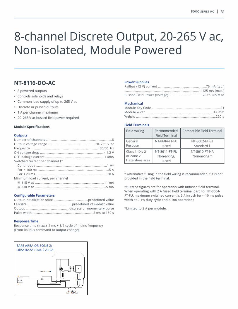
8000 series i/o | 31
NT-8116-DO-AC• 8 powered outputs• Controls solenoids and relays• Common load supply of up to 265 V ac• Discrete or pulsed outputs• 1 A per channel maximum• 20–265 V ac bussed field power required
Module Specifications
OutputsNumber of channels .........................................................................8Output voltage range ....................................................20–265 V acFrequency ...........................................................................50/60 HzON voltage drop ......................................................................< 1.2 VOFF leakage current .................................................................< 4mASwitched current per channel ††
Continuous ..............................................................................1 A*For < 100 ms ..............................................................................5 AFor < 20 ms ...............................................................................20 A
Minimum load current, per channel@ 115 V ac ............................................................................11 mA@ 230 V ac ..............................................................................5 mA
Configurable ParametersOutput initialization state ......................................predefined valueFail-safe .................................................predefined value/last valueOutput ................................................discrete or momentary pulsePulse width ...................................................................2 ms to 130 s
Response TimeResponse time (max.) .2 ms + 1/2 cycle of mains frequency(From Railbus command to output change)
Power SuppliesRailbus (12 V) current .....................................................75 mA (typ.)......................................................................................125 mA (max.)Bussed Field Power (voltage) .....................................20 to 265 V ac
MechanicalModule Key Code ............................................................................F1Module width ..........................................................................42 mmWeight ........................................................................................220 g
Field Terminals
Field Wiring Recommended Field Terminal
Compatible Field Terminal
General Purpose
NT-8604-FT-FUFused
NT-8602-FT-STStandard †
Class 1, Div 2 or Zone 2 Hazardous area
NT-8611-FT-FUNon-arcing,
Fused
NT-8610-FT-NANon-arcing †
† Alternative fusing in the field wiring is recommended if it is not provided in the field terminal.
†† Stated figures are for operation with unfused field terminal. When operating with 2 A fused field terminal part no. NT-8604-FT-FU, maximum switched current is 5 A inrush for < 10 ms pulse width at 0.1% duty cycle and < 108 operations
*Limited to 3 A per module.
8-channel Discrete Output, 20-265 V ac, Non-isolated, Module Powered

32 | novatech
NT-8118-DO-AC• 8 fully isolated semiconductor switched outputs• Controls solenoids and relays• For load supplies of up to 250 V ac• Discrete or pulsed outputs• 1 A per channel switched
Module Specifications
OutputsNumber of channels ..............................................................................8Output voltage range .....................................................20–265 V acFrequency ...........................................................................50/60 HzON voltage drop ......................................................................< 1.2 VOFF leakage current ................................................................< 4 mASwitched current per channel †
Continuous ...............................................................................1 A*For < 100 ms ...............................................................................5 AFor < 20 ms ...............................................................................20 A
Minimum load current, per channel@ 115 V ac ............................................................................11 mA@ 230 V ac ..............................................................................5 mA
Configurable ParametersOutput initialization state ......................................predefined valueFail-safe .................................................predefined value/last valueOutput ................................................discrete or momentary pulsePulse width ...................................................................2 ms to 130 s
Response TimeResponse time (max.) .2 ms + 11⁄42 cycle of mains frequency(From Railbus command to output change)
Power SuppliesRailbus (12 V) current .....................................................75 mA (typ.)......................................................................................125 mA (max.)Bussed Field Power .......................................................not required
MechanicalModule Key Code ............................................................................F4Module width ..........................................................................42 mmWeight ........................................................................................220 g
Field Terminals
Field Wiring Recommended Field Terminal
Compatible Field Terminal
General Purpose
NT-8604-FT-FUFused
NT-8602-FT-STStandard
Class 1, Div 2 or Zone 2 Hazardous area
NT-8611-FT-FUNon-arcing,
Fused
NT-8610-FT-NANon-arcing
† Stated figures are for operation with unfused field terminal. When operating with 2 A fused field terminal part no. NT-8604-FT-FU, maximum switched current is 5 A inrush for < 10 ms pulse width at 0.1% duty cycle and < 108 operations.
* Limited to 3 A per module.
8-channel Discrete Output20-265 V ac, Isolated, Unpowered
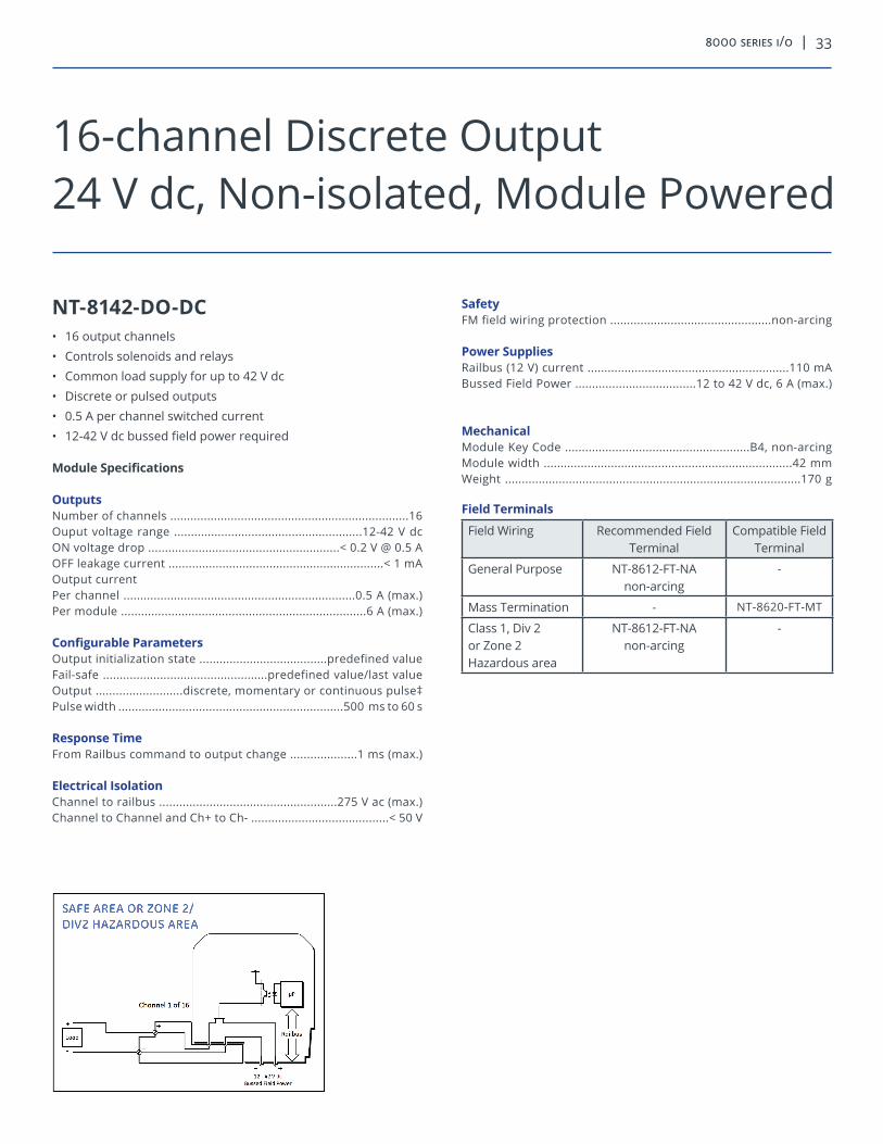
8000 series i/o | 33
NT-8142-DO-DC• 16 output channels• Controls solenoids and relays• Common load supply for up to 42 V dc• Discrete or pulsed outputs• 0.5 A per channel switched current• 12-42 V dc bussed field power required
Module Specifications
OutputsNumber of channels .......................................................................16Ouput voltage range ........................................................12-42 V dcON voltage drop .........................................................< 0.2 V @ 0.5 AOFF leakage current ................................................................< 1 mAOutput currentPer channel .....................................................................0.5 A (max.)Per module .........................................................................6 A (max.)
Configurable ParametersOutput initialization state ......................................predefined valueFail-safe .................................................predefined value/last valueOutput ..........................discrete, momentary or continuous pulse‡Pulse width ...................................................................500 ms to 60 s
Response TimeFrom Railbus command to output change ....................1 ms (max.)
Electrical IsolationChannel to railbus .....................................................275 V ac (max.)Channel to Channel and Ch+ to Ch- .........................................< 50 V
SafetyFM field wiring protection ................................................non-arcing
Power SuppliesRailbus (12 V) current ............................................................110 mA Bussed Field Power ....................................12 to 42 V dc, 6 A (max.)
MechanicalModule Key Code .......................................................B4, non-arcingModule width ..........................................................................42 mmWeight ........................................................................................170 g
Field Terminals
Field Wiring Recommended Field Terminal
Compatible Field Terminal
General Purpose NT-8612-FT-NAnon-arcing
-
Mass Termination - NT-8620-FT-MT
Class 1, Div 2 or Zone 2 Hazardous area
NT-8612-FT-NAnon-arcing
-
16-channel Discrete Output24 V dc, Non-isolated, Module Powered

34 | novatech
NT-8129-IO-DC • 8 Channels any combination of inputs and outputs• Non-arcing inputs and outputs• Output channels rated up to 2 A continuous• Inputs for dry contact switches• 24 V dc bussed field power required
Module Specifications
InputsON/OFF threshold current ............................................0.9 mA (typ.)O/C Voltage ........................24 V dc (typ.)—depends on BFP SupplyWetting current .............................................................1.2 mA (typ.)Minimum pulse width detected .................................................5 msMax input frequency in pulse counting mode (no debounce) 30 HzIsolation (any channel to Railbus) .......................................250 V ac
OutputsMaximum Output Current per Channel ........................................2 AMaximum Output Current per ModuleContinuous .....................................................................................6 ANon-continuous (< 10 seconds) .....................................................8 A
Configurable ParametersInput Filter time interval .........................................0 to 8 s (in 1 ms steps)Earth Leakage Detection Channel ........................................ON/OFFLatch inputs ...............................................................enable/disableLatch polarity ..........................................latch on high/latch on lowPulse counting .....................up transition/down transition/disableLine fault detection ........... none/open circuit/open & short circuitOutputOutput type ...................................................pulse/discrete/patternPulse width .....................................................................1 ms to 60 sLine fault detection* ........open line & short circuit detect/disable* Normally de-energized channels only
Response TimeInput Signal change to availability on Railbus ...............5 ms (max.)Railbus command to output change ..............................1 ms (max.)
SafetyFM field wiring protection ................................................non-arcing
Resistance Measurement AccuracyFor normally de-energized output open and short-circuit detection.With forward biased test current.......................................± (3.4% +5.3 Ω) for line resistance ≤ 220 Ωgreater of: ± 7% or ± (3.1% +27 Ω) for line resistance > 220 Ω, < 1 kΩWith reverse biased test current....................................................greater of: ± 7% or ± (3.1% +430 Ω)
MechanicalModule Key Code............................................................................B6Module width ..........................................................................42 mmWeight.........................................................................................210 g
Field Terminals
Field Wiring Recommended Field Terminal
Compatible Field Terminal
General Purpose NT-8604-FT-FUFused
NT-8602-FT-STStandard †
Class 1, Div 2 or Zone 2 Hazardous Area
NT-8611-FT-FU Non-arcing, Fused
NT-8610-FT-NANon-arcing †
† Alternative fusing in the field wiring is recommended if it is not provided in the field terminal.† † The total instantaneous switched current should not exceed the following: 10 A for < 100 ms18 A for < 20 ms* Limited to 6 A per module‡ Consult NovaTech for availability
Power SuppliesSystem Power Supply .............................50 mA (typ.), 70 mA (max.)Bussed Field Power SupplyAll channels configured as inputs ................................50 mA (max)Any channels configured as output ...50 mA + output load currents
8-channel Digital Input/Output24 V dc, Non-isolated, Module Powered

8000 series i/o | 35
NT-8201-HI-IS (Intrinsically Safe)• 8 single-ended 4 - 20 mA input channels• Intrinsically safe (IS) field circuits• HART pass-through• HART variable and status reporting• For 2-wire transmitters• Built-in IS power supply
Module Specifications
Inputs Number of channels .................................................8, single-endedNominal signal range (span) ............................................4 to 20 mAFull signal range ............................................................0.5 to 22 mALine fault detectionShort circuit current .........................................................> 21.5 mAVoltage to transmitter @ 20 mA ......................................15 V (min.)Accuracy (@ 25°C) .................................................................±20 µAResolution ................................................................................16 bitsTemperature Stability(-40°C to +70°C) .........................................± 0.006% of span per °CIsolation
(any channel to Railbus) .....................................................60 V ac(between channels in same module).....................................none
Configurable ParametersInput filter time constant ...................................user defined valueInput dead zone .................................................user defined valueDrive on failsafe ...................................disable/upscale/downscaleChannel status ...........................................................active/inactiveHART variable and status reporting .........................enable/disableAlarms ..................................................high, high-high, low, low-lowAlarm deadband (hysteresis) .............................user defined value
Response TimeSignal change to availability on Railbus
4–20 mA mode ...........................................................33 ms (max.)HART mode .......................................................0.75 s per channel
SafetyField wiring protection ...................................................[EEx ia] IICSafety description (each channel).....................................................Uo = 28 V, Io = 93 mA, Po = 0.65 WFM entity parameters .............................Voc ≤ 28 V dc, Isc ≤ 93 mA.................................................................Ca ≤ 0.14 μF, La ≤ 4.38 mH
Power SuppliesIS Railbus (12 V) current (all channels @ 22 mA)........................................................................................600 mA (typ.)Power dissipation within module .................................4.2 W (max.)
MechanicalModule Key Code ...........................................................................A1Module width ...........................................................................42 mmWeight .........................................................................................260 g
Field Terminals
Field Wiring Recommended Field Terminal
Compatible Field Terminal
IS Standard NT-8621-FT-IS -
IS Loop Disconnect
NT-8622-FT-IS -
8-channel IS Analog Input4-20 mA with HART®

36 | novatech
NT-8230-AI-IS (Intrinsically Safe)• 8 single-ended input channels• Intrinsically safe (IS) field circuits• 0–10 V/100 Ω–10 kΩ potentiometer• 4-20 mA current input with additional burden resistor• True zero on voltage input• Open circuit field wiring detection
Module Specifications
Inputs Number of channels .................................................8, single-ended0–10 V input characteristicsNominal signal range (span) ...............................................0 to 10 VFull signal range .................................................................0 to +11 VResolution.................................................................................16 bitsInput impedance ..................................................................> 100 kΩUnder-range indication ........................................................-100 mVPotentiometer input characteristicsNominal signal range (span) ...............................0 to 100% of travelPotentiometer resistance .........................................100 Ω to 10 kΩExcitation voltage (nom.) .......................10 V (from 2.2 kΩ source)Resolution (≥ 1 kΩ potentiometer) .......................................14 bitsResolution (100 Ω potentiometer) ........................................11 bitsAccuracy (at 25°C) ......................................................± 0.1% of spanIsolation(any channel to Railbus) .......................................................100 V ac(between channels) ....................................................................none
Configurable ParametersInput type (per channel) ...............................voltage/potentiometerAlarms ............................................................................high and lowAlarm deadband (hysteresis) ..............................user defined valueInput filter time constant ....................................user defined valueInput dead zone ..................................................user defined valueDrive on open circuit ..........................disabled/upscale/downscaleChannel status ........................................................... active/inactiveLead compensation .............................................user defined value
Response TimeSignal change to availability on Railbus ......................33 ms (max.)Open circuit line fault detection time ......................................≤ 5 s
SafetyField wiring protection .......................................................[EExia] IICSafety description (each channel - non linear output) .............................................Uo ≤ 15.75 V, Io ≤ 20 mA, Po ≤ 0.315 WFM entity parameters .............................Voc = 15.75 V, Isc = 20 mA.......................................................................Ca = 0.22 μF, La = 5 mH
Power SuppliesIS Railbus (12 V) currentTypical .....................................................................................200 mAMax with voltage/current inputs ..........................................250 mAMax. with 100 Ω potentiometer inputs .................................350 mAPower dissipation within moduleMax with voltage/current inputs .................................................3 WMax. with 100 Ω potentiometer inputs ....................................4.2 W
MechanicalModule Key Code ...........................................................................C4Module width ..........................................................................42 mmWeight ........................................................................................200 g
Field Terminals
Field Wiring Recommended Field Terminal
Compatible Field Terminal
IS Standard NT-8623-FT-IS -
8-channel IS Analog Input0-10 V/Potentiometer Input

8000 series i/o | 37
NT-8205-TI-IS (Intrinsically Safe)• 8 input channels• Intrinsically safe (IS) field circuits• Thermocouple and mV• Cold junction compensation (internal or remote)• Built-in thermocouple linearisation• Channels independently configurable• Open-circuit field wiring detection
Module Specifications
InputsNumber of channels .........................................................................8THCs types ..........................B, E, J, K, N R, S, or T to EN 60584-1: 1995..........................................user definable linearisation table, note 1
Input Ranges
Input Type Range
mV -8 to +24 mV
-20 to +60 mV
-33.333 to +100 mV
-100 to +100 mV
Thermocouples: B 0°C to 1820 °C
E -270°C to +1000 °C
J -210°C to +1200 °C
K -270°C to +1372 °C
N -270°C to +1300 °C
R & S -50°C to +1768.1 °C
T -270°C to +400 °C
Accuracy
Tamb mV Inputs THC Inputs
25°C ± 0.05% ± 0.05%
+10°C to +40 °C ± 0.08% ± 0.1%
-40°C to +70 °C ± 0.18% ± 0.3%
Temperature drift ........................................< ± 0.003% of span/°C Cold junction compensation error†..........< ± 1°C (-40°C to +70 °C)Resolution ................................................................................16 bits Common mode rejection ................................> 87 dB @ 50/60 HzSeries mode rejection .......................................> 50 dB @ 50/60 Hz Common mode voltage between channels ...................± 5 V (max.) Absolute maximum input voltage ......................................... ± 30 V Isolation (any channel to Railbus) .....................................60 V peak
Response TimeSignal change to availability on Railbus ....................600 ms (max.)O/C sensor detection ...............................................................≤ 10 s
SafetyChannels 1, 2, 3, 4, 7, 8, wired as separate IS circuits .................................................Uo = 16.4 V; Io = 79 mA; Po = 0.33 WChannels 5 and 6, wired as separate IS circuits....................................................Uo = 1 V, lo + 1.1 mA, Po = 0.3 mW(Input terminals are equivalent to non-energy storing apparatus) FM entity parametersChannels 1, 2, 3, 4, 7, 8, wired as separate IS circuits.........................................Voc = 16.4 V; Isc= 63.7 mA; Po = 131 mWChannels 5 and 6, wired as separate intrinsic safety circuits.....................................................Uo = 1 V, lo + 1 mA, Po = 0.25 mW
Power SuppliesIS Railbus (12 V) current .............................................120 mA (max.) Power Dissipation within module .................................1.5 W (max.)
MechanicalModule Key Code ...........................................................................C1Module width ..........................................................................42 mmWeight ........................................................................................245 g*Cold junction compensation located in recommended field terminal
Field Terminals
Field Wiring Recommended Field Terminal
Compatible Field Terminal
IS THC NT-8625-FT-IS -
8-channel IS Analog InputThermocouple and mV
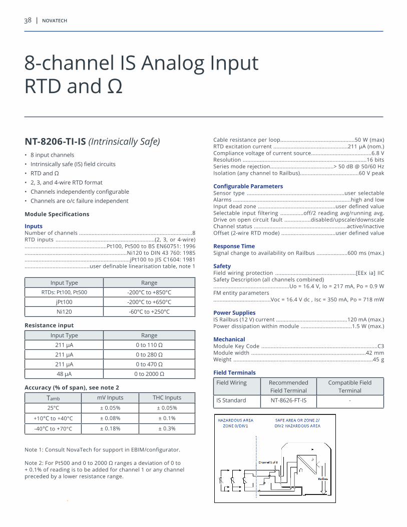
38 | novatech
NT-8206-TI-IS (Intrinsically Safe)• 8 input channels• Intrinsically safe (IS) field circuits• RTD and Ω• 2, 3, and 4-wire RTD format• Channels independently configurable• Channels are o/c failure independent
Module Specifications
Inputs Number of channels .........................................................................8RTD inputs ................................................................(2, 3, or 4-wire).....................................................Pt100, Pt500 to BS EN60751: 1996..................................................................Ni120 to DIN 43 760: 1985....................................................................jPt100 to JIS C1604: 1981..........................................user definable linearisation table, note 1
Input Type Range
RTDs: Pt100, Pt500 -200°C to +850°C
jPt100 -200°C to +650°C
Ni120 -60°C to +250°C
Resistance input
Input Type Range
211 μA 0 to 110 Ω
211 μA 0 to 280 Ω
211 μA 0 to 470 Ω
48 μA 0 to 2000 Ω
Accuracy (% of span), see note 2
Tamb mV Inputs THC Inputs
25°C ± 0.05% ± 0.05%
+10°C to +40°C ± 0.08% ± 0.1%
-40°C to +70°C ± 0.18% ± 0.3%
Note 1: Consult NovaTech for support in EBIM/configurator.
Note 2: For Pt500 and 0 to 2000 Ω ranges a deviation of 0 to + 0.1% of reading is to be added for channel 1 or any channel preceded by a lower resistance range.
Cable resistance per loop................................................50 W (max)RTD excitation current ................................................211 μA (nom.)Compliance voltage of current source.......................................6.8 VResolution ................................................................................16 bitsSeries mode rejection.........................................> 50 dB @ 50/60 HzIsolation (any channel to Railbus)......................................60 V peak
Configurable ParametersSensor type ...............................................................user selectableAlarms ............................................................................high and lowInput dead zone ..................................................user defined valueSelectable input filtering ...............off/2 reading avg/running avg.Drive on open circuit fault .................disabled/upscale/downscaleChannel status ............................................................active/inactiveOffset (2-wire RTD mode) ...................................user defined value
Response TimeSignal change to availability on Railbus ....................600 ms (max.)
SafetyField wiring protection ....................................................[EEx ia] IICSafety Description (all channels combined).................................................Uo = 16.4 V, Io = 217 mA, Po = 0.9 WFM entity parameters.....................................Voc = 16.4 V dc , Isc = 350 mA, Po = 718 mW
Power SuppliesIS Railbus (12 V) current ..............................................120 mA (max.)Power dissipation within module .................................1.5 W (max.)
MechanicalModule Key Code ...........................................................................C3Module width ..........................................................................42 mmWeight ..........................................................................................45 g
Field Terminals
Field Wiring Recommended Field Terminal
Compatible Field Terminal
IS Standard NT-8626-FT-IS -
8-channel IS Analog InputRTD and Ω
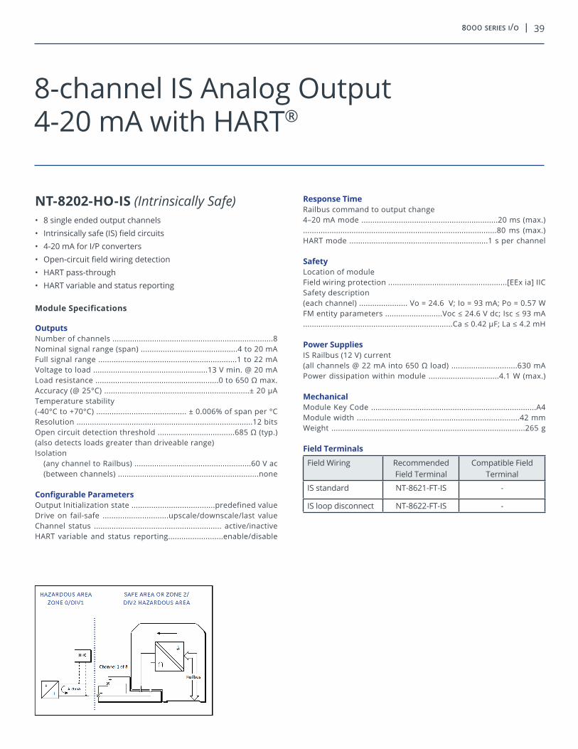
8000 series i/o | 39
NT-8202-HO-IS (Intrinsically Safe)• 8 single ended output channels• Intrinsically safe (IS) field circuits• 4-20 mA for I/P converters • Open-circuit field wiring detection• HART pass-through• HART variable and status reporting
Module Specifications
OutputsNumber of channels .........................................................................8Nominal signal range (span) ............................................4 to 20 mAFull signal range ...............................................................1 to 22 mAVoltage to load ....................................................13 V min. @ 20 mALoad resistance ........................................................0 to 650 Ω max.Accuracy (@ 25°C) ..................................................................± 20 μATemperature stability(-40°C to +70°C) ......................................... ± 0.006% of span per °CResolution ................................................................................12 bitsOpen circuit detection threshold ...................................685 Ω (typ.)(also detects loads greater than driveable range)Isolation
(any channel to Railbus) .....................................................60 V ac(between channels) ................................................................none
Configurable ParametersOutput Initialization state ......................................predefined valueDrive on fail-safe ..............................upscale/downscale/last valueChannel status .......................................................... active/inactiveHART variable and status reporting.........................enable/disable
Response TimeRailbus command to output change4–20 mA mode ..............................................................20 ms (max.)........................................................................................80 ms (max.) HART mode ...............................................................1 s per channel
SafetyLocation of moduleField wiring protection ......................................................[EEx ia] IICSafety description(each channel) ...................... Vo = 24.6 V; Io = 93 mA; Po = 0.57 W FM entity parameters ..........................Voc ≤ 24.6 V dc; Isc ≤ 93 mA ....................................................................Ca ≤ 0.42 µF; La ≤ 4.2 mH
Power SuppliesIS Railbus (12 V) current (all channels @ 22 mA into 650 Ω load) ..............................630 mA Power dissipation within module ................................4.1 W (max.)
MechanicalModule Key Code ...........................................................................A4Module width ..........................................................................42 mmWeight ........................................................................................265 g
Field Terminals
Field Wiring Recommended Field Terminal
Compatible Field Terminal
IS standard NT-8621-FT-IS -
IS loop disconnect NT-8622-FT-IS -
8-channel IS Analog Output4-20 mA with HART®

40 | novatech
NT-8204-AO-IS (Intrinsically Safe)• 8 single ended output channels• Intrinsically safe (IS)• Conventional 4-20 mA • Open-circuit field wiring detection• For I/P converters
Module Specifications
OutputsNumber of channels .........................................................................8Nominal signal range (span) ............................................4 to 20 mAFull signal range ...............................................................1 to 22 mAVoltage to load ....................................................13 V min. @ 20 mALoad resistance ...............................................................450 Ω max.Accuracy (@ 25°C) ..................................................................± 20 μATemperature stability(-40°C to +70°C) ......................................... ± 0.006% of span per °CResolution ................................................................................12 bitsOpen circuit detection threshold ..................................0.7 ± 0.2 mAIsolation
(any channel to Railbus) .....................................................60 V ac(between channels) ................................................................none
Configurable ParametersOutput Initialization state ......................................predefined valueDrive on fail-safe ..............................upscale/downscale/last valueChannel status .......................................................... active/inactive
Response TimeRailbus command to output change4-20 mA mode ..............................................................25 ms (max.)........................................................................................80 ms (max.)
SafetyLocation of moduleField wiring protection ......................................................[EEx ia] IICSafety description(each channel) ...................... Vo = 24.6 V; Io = 93 mA; Po = 0.57 W FM entity parameters ..........................Voc ≤ 24.6 V dc; Isc ≤ 93 mA....................................................................Ca ≤ 0.42 µF; La = 4.2 mH
Power SuppliesIS Railbus (12 V) current (all channels @ 22 MA into 650 Ω load) ................................530 mA Power dissipation within module .................................3.8 W (max.)
MechanicalModule Key Code ...........................................................................A4Module width ..........................................................................42 mmWeight ........................................................................................245 g
Field Terminals
Field Wiring Recommended Field Terminal
Compatible Field Terminal
IS standard NT-8621-FT-IS -
IS loop disconnect NT-8622-FT-IS -
8-channel IS Analog Output4-20 mA

8000 series i/o | 41
NT-8220-DI-IS (Intrinsically Safe)• 16 single-ended input channels• Intrinsically safe (IS) field circuits• Simple apparatus, dry contacts, or IS proximity detectors• Open and short-circuit field wiring detection
Module Specifications
InputsNumber of channels .......................................................................16OFF current .........................................................................< 1.2 mAON current ..........................................................................> 2.1 mASwitching hysteresis ....................................................200 μA (nom.)Applicable specifications ....................................NAMUR, DIN19234Voltage applied to sensor ..................7.0 to 9.0 V from 1 kΩ ± 10%Output (wetting) current@ 100 Ω line impedance ........................................................ > 6 mALine fault detectionShort circuit ...........................................................................< 100 ΩOpen circuit ...........................................................................> 90 kΩMaximum input frequencyin pulse counting mode ............................................................20 HzMinimum pulse width detected ...............................................45 ms
Configurable ParametersSelectable input filter ..............................fast, slow, or user defined(User defined permits 0 to 512 ms values in 3 ms steps)Latch inputs ...............................................................enable/disableLatch polarity .........................................latch on high/latch on lowPulse counting ..........................................................enable/disableLine fault detection ....................................................enable/disable
Response TimeField event to availability on Railbus..............................6 ms (max.)
SafetyField wiring protection ......................................................[EEx ia] IICSafety Description (each channel)(each channel) ........................Uo = 10.5 V, Io = 14 mA, Po = 0.04 WFM Entity parameters ...........................Voc ≤ 10.5 V dc, Isc ≤ 14 mA...................................................................Ca ≤ 2.67 μF, La ≤ 176 mHIsolation(any channel to Railbus) .........................................................60 V ac(channels arranged in two groups of eight, with returns commoned within each group)
Power SuppliesIIS Railbus (12 V) current(16-channel mode) .....................................................350 mA (max.)(8-channel mode) ........................................................285 mA (max.)
MechanicalModule Key Code ...........................................................................B1Module width ..........................................................................42 mmWeight ........................................................................................170 g
Field Terminals
Field Wiring Recommended Field Terminal
Compatible Field Terminal
IS, 16-channel NT-8623-FT-IS -
IS, 8-channel loop disconnect
NT-8624-FT-IS -
16-channel IS Discrete InputSwitch/Proximity Detector
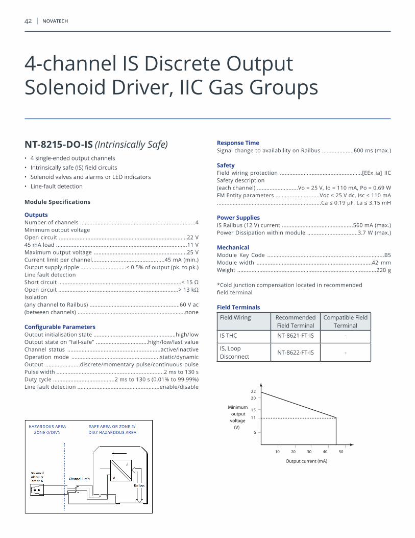
42 | novatech
NT-8215-DO-IS (Intrinsically Safe)• 4 single-ended output channels• Intrinsically safe (IS) field circuits• Solenoid valves and alarms or LED indicators• Line-fault detection
Module Specifications
OutputsNumber of channels .........................................................................4Minimum output voltageOpen circuit .................................................................................22 V45 mA load ...................................................................................11 VMaximum output voltage ...........................................................25 VCurrent limit per channel..............................................45 mA (min.)Output supply ripple .............................< 0.5% of output (pk. to pk.)Line fault detectionShort circuit ..............................................................................< 15 ΩOpen circuit ............................................................................> 13 kΩIsolation(any channel to Railbus) .........................................................60 V ac(between channels) ....................................................................none
Configurable ParametersOutput initialisation state ....................................................high/lowOutput state on “fail-safe” .................................high/low/last valueChannel status ...........................................................active/inactiveOperation mode ........................................................static/dynamicOutput ......................discrete/momentary pulse/continuous pulsePulse width ....................................................................2 ms to 130 sDuty cycle .......................................2 ms to 130 s (0.01% to 99.99%)Line fault detection ....................................................enable/disable
Response TimeSignal change to availability on Railbus ....................600 ms (max.)
SafetyField wiring protection ....................................................[EEx ia] IICSafety description(each channel) ..........................Vo = 25 V, Io = 110 mA, Po = 0.69 WFM Entity parameters ............................Voc ≤ 25 V dc, Isc ≤ 110 mA..................................................................Ca ≤ 0.19 μF, La ≤ 3.15 mH
Power SuppliesIS Railbus (12 V) current .............................................560 mA (max.) Power Dissipation within module ................................3.7 W (max.)
MechanicalModule Key Code ..........................................................................B5Module width .........................................................................42 mmWeight ........................................................................................220 g
*Cold junction compensation located in recommended field terminal
Field Terminals
Field Wiring Recommended Field Terminal
Compatible Field Terminal
IS THC NT-8621-FT-IS -
IS, Loop Disconnect
NT-8622-FT-IS -
11
15
20
22
5
Output current (mA)
Minimumoutput
voltage(V)
10 20 30 40 50
4-channel IS Discrete OutputSolenoid Driver, IIC Gas Groups

8000 series i/o | 43
This page intentionally left blank.

novatechweb.com
Copyright © 2018 NovaTech, LLC. All rights reserved. All brand and product names mentioned in this document are trademarks of their respective owners. NovaTech, is a registered trademark of NovaTech, LLC. IThe information in this literature is subject to change without notice and is not to be construed as a warranty. BR_8000IO_120418