80 Meter CW ARDF Receiverkd4nga.net/Resources/PROJECTS/80m_ardf_rx.pdfconfigured as a Gilbert cell...
20
Page 1 The FOXFINDER-80 WEB UPDATE (DRAFT v2.0 SUBJECT TO CHANGE) A lot of modifications have occurred since the introduction of the original article. This update incorporates them and also corrects some errors that got into the original published text. Also modifications to the FAR circuit boards are described along with modifications from other users. Introduction The purpose of this article is to describe how to build a simple ARDF receiver for 80-Meter international style transmitter hunting. The criteria for the receiver is that it must be easy to align with out expensive lab equipment and all the parts must be easy to locate. In the case of this receiver the majority of the parts were purchased from Digikey, Newark, Radio Shack and Radio Shack Unlimited. One component was purchased from Amidon associates and another part was located at a local surplus store (10 turn knob pot used for VFO control). 80 Meter CW ARDF Receiver Unlike VHF direction finding equipment, very little information about complete 80-meter DF sets can be found in the United States. Bits and pieces of information relating to DF antennas can be found in books such as the current edition of the ARRL antenna handbook. Another source of information is a book by Joe Moell K0OV titled “Transmitter Hunting Radio Direction Simplified”. Also a new book by Joe Carr is a good source of information about loop antennas, its title is “Joe Carr’s Loop Antenna Handbook”. Information on small CW receivers can be found in the ARRL handbook, QRP handbooks and the Internet. Back in May of 1999 I started developing my first portable receiver for use in the Portland games. The result was an operational receiver that was used in the games. I was the only US contestant with my own 80meter equipment. All other US contestants used equipment provided by the Europeans. The receiver described in this paper is my second-generation design. My first version receiver shown in figure 1 was the one that was used in the Portland event. It was a Superhet with an 8MHz IF and a ferrite rod antenna with a vertical sense whip (more on why a sense antenna is required later). Several improvements where made based on my experience using the original receiver during the 1999 hunt. Its my hope that this receiver will inspire the beginning of experimenting with homebuilt HF DF sets in the United States.
Transcript of 80 Meter CW ARDF Receiverkd4nga.net/Resources/PROJECTS/80m_ardf_rx.pdfconfigured as a Gilbert cell...
Page 1
The FOXFINDER-80 WEB UPDATE(DRAFT v2.0 SUBJECT TO CHANGE)
A lot of modifications have occurred since the introduction of the original article. This update incorporatesthem and also corrects some errors that got into the original published text. Also modifications to the FARcircuit boards are described along with modifications from other users.
IntroductionThe purpose of this article is to describe how to build a simple ARDF receiver for 80-Meter internationalstyle transmitter hunting. The criteria for the receiver is that it must be easy to align with out expensive labequipment and all the parts must be easy to locate. In the case of this receiver the majority of the parts werepurchased from Digikey, Newark, Radio Shack and Radio Shack Unlimited. One component waspurchased from Amidon associates and another part was located at a local surplus store (10 turn knob potused for VFO control).
80 Meter CW ARDF ReceiverUnlike VHF direction finding equipment, very little information about complete 80-meter DF sets can befound in the United States. Bits and pieces of information relating to DF antennas can be found in bookssuch as the current edition of the ARRL antenna handbook. Another source of information is a book by JoeMoell K0OV titled “Transmitter Hunting Radio Direction Simplified”. Also a new book by Joe Carr is agood source of information about loop antennas, its title is “Joe Carr’s Loop Antenna Handbook”.
Information on small CW receivers can be found in the ARRL handbook, QRP handbooks and the Internet.
Back in May of 1999 I started developing my first portable receiver for use in the Portland games. Theresult was an operational receiver that was used in the games. I was the only US contestant with my own80meter equipment. All other US contestants used equipment provided by the Europeans.
The receiver described in this paper is my second-generation design. My first version receiver shown infigure 1 was the one that was used in the Portland event. It was a Superhet with an 8MHz IF and a ferriterod antenna with a vertical sense whip (more on why a sense antenna is required later). Severalimprovements where made based on my experience using the original receiver during the 1999 hunt. Its myhope that this receiver will inspire the beginning of experimenting with homebuilt HF DF sets in the UnitedStates.
Page 2
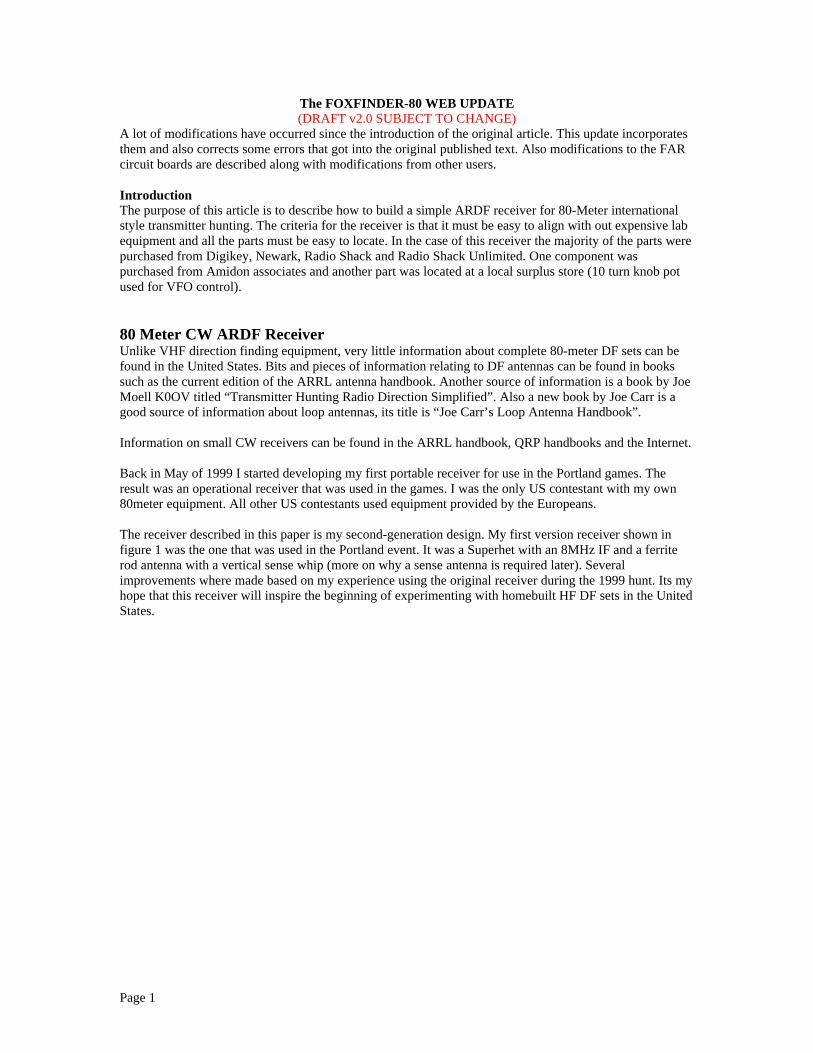
Figure 1 Receiver used in 1999 Portland games by Jerry Boyd WB8WFK
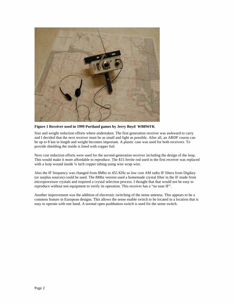
Size and weight reduction efforts where undertaken. The first generation receiver was awkward to carryand I decided that the next receiver must be as small and light as possible. After all, an ARDF course canbe up to 8 km in length and weight becomes important. A plastic case was used for both receivers. Toprovide shielding the inside is lined with copper foil.
Next cost reduction efforts were used for the second-generation receiver including the design of the loop.This would make it more affordable to reproduce. The $15 ferrite rod used in the first receiver was replacedwith a loop wound inside ¼ inch copper tubing using wire wrap wire.
Also the IF frequency was changed from 8Mhz to 455 KHz so low cost AM radio IF filters from Digikey(or surplus sources) could be used. The 8Mhz version used a homemade crystal filter in the IF made frommicroprocessor crystals and required a crystal selection process. I thought that that would not be easy toreproduce without test equipment to verify its operation. This receiver has a “no tune IF”.
Another improvement was the addition of electronic switching of the sense antenna. This appears to be acommon feature in European designs. This allows the sense enable switch to be located in a location that iseasy to operate with one hand. A normal open pushbutton switch is used for the sense switch.

Page 3
Block Diagram and receiver operation
MixerTunedCircuit
(band pass)&
FET Buffer
Loop DF Antenna
VFO (LO)
IF Ceramic Filter
Headphones (32 Ohm)
Version 3 WB8WFK ARDF CW superhet receiverRevised November 2001
(Low side injection)
IF Gain stage
FL1 455Khzproduct detector (mixer)
BFO (beat frequencyoscillator)
Audio AMP
WB8WFK11-18-2001
U3 LM386U1 MC1350
U2 NE602
U2 NE602
Q1 MPF102 (FET)
U4 NE602Adjustable Gain~ 50 DB range
Diode Reverse PolarityProtection
VDDVBATMain Power(part of AF gaincontrol)
Receiver Gain
AF GainU2 NE602
Sense Amp
V_RF_STAGE
Sense Antenna
Q3 MPF102 (FET)
Sense Switch (no push button)
D3
L2
L1
VDD
Figure 2 HF DF receiver block diagram
Refer to Figure 2 for an overview of the receiver. The signal is first picked up by L1 the primary DFantenna (L2 the sense-coupling loop will be discussed later). L1 and L2 are housed in a faraday shieldmade from ¼ inch copper tubing. L1 presents the typical figure eight pattern (refer to figure 3A) Thevoltage induced into the DF loop is amplified by Q1 FET amplifier.
Following amplification by Q1 the signal is passed on to U4 a Phillips NE602 (or SA602). U4 isconfigured as a Gilbert cell mixer and varactor diode tuned VFO. The VFO is operating 455Khz below thedesired received signal (referred to as low side injection). The data sheet specifies a conversion gain of14DB at 45 MHz. No graph was provided to determine the value at HF.
After conversion to the IF frequency the signal is filtered by FL1 to remove undesired signals. FL1 has a6DB bandwidth of 4Khz. U1 is an IF amplifier with adjustable gain control. The data sheet specifies a gainof 50DB (at 45 Mhz) and a gain control range of 60DB (at 45 Mhz). Adjusting the AGC voltage controlsthe gain of U1. The electronic gain control circuit pot accomplishes this. Following amplification by U1 thesignal is converted to base band (audio) by product detector U2 and BFO U2. A low cost ceramic resonatordetermines the BFO frequency. U2 is also a Phillips NE602 (or SA602).
After conversion to base band the signal is amplified to a level to drive a stereo headphone by U3. U3 is anational semiconductor LM386 configured for a gain of about 50 (set by 1Uf ceramic capacitor C7). Theheadphones can be any set that has Z of 32 ohms. A quick note about using cheep headsets, they may havelower efficiency than name brands. I can notice the difference between a Sony set verses a $5 no name.However the $5 version works.
Electronic gain control is provided via the IF stage by using a gain control voltage supplied via a variableresistor (POT). Manuel control is desired for a DF receiver, this is because automatic AGC action wouldadjust the gain of the receiver as the loop is turned, this could make finding the null difficult because ofAGC trying to maintain a constant volume level.
Page 4
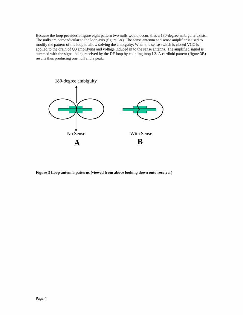
Because the loop provides a figure eight pattern two nulls would occur, thus a 180-degree ambiguity exists.The nulls are perpendicular to the loop axis (figure 3A). The sense antenna and sense amplifier is used tomodify the pattern of the loop to allow solving the ambiguity. When the sense switch is closed VCC isapplied to the drain of Q3 amplifying and voltage induced in to the sense antenna. The amplified signal issummed with the signal being received by the DF loop by coupling loop L2. A cardioid pattern (figure 3B)results thus producing one null and a peak.
No Sense
AWith Sense
B
180-degree ambiguity
Figure 3 Loop antenna patterns (viewed from above looking down onto receiver)
Page 5
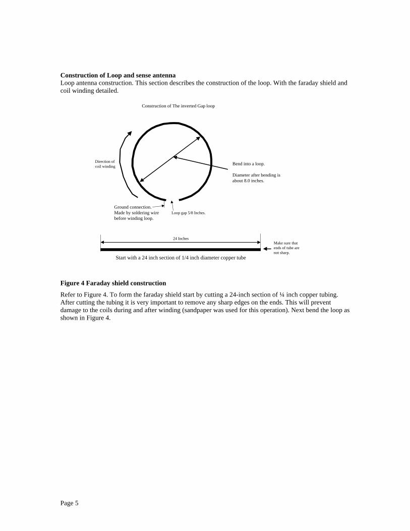
Construction of Loop and sense antennaLoop antenna construction. This section describes the construction of the loop. With the faraday shield andcoil winding detailed.
Construction of The inverted Gap loop
Ground connection.Made by soldering wirebefore winding loop.
24 Inches
Start with a 24 inch section of 1/4 inch diameter copper tube
Bend into a loop. Diameter after bending is about 8.0 inches.
Make sure thatends of tube arenot sharp.
Loop gap 5/8 Inches.
Direction ofcoil winding
Figure 4 Faraday shield construction
Refer to Figure 4. To form the faraday shield start by cutting a 24-inch section of ¼ inch copper tubing.After cutting the tubing it is very important to remove any sharp edges on the ends. This will preventdamage to the coils during and after winding (sandpaper was used for this operation). Next bend the loop asshown in Figure 4.
Page 6
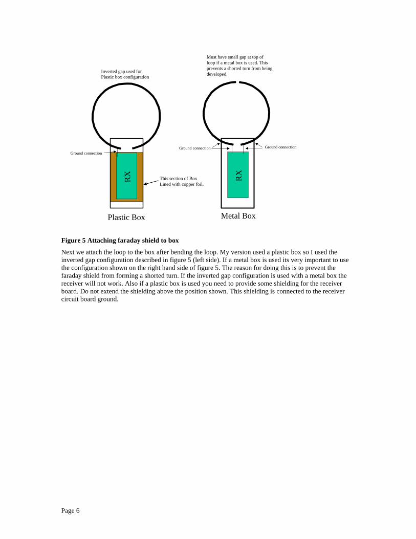
Plastic Box Metal Box
Inverted gap used forPlastic box configuration
Must have small gap at top ofloop if a metal box is used. Thisprevents a shorted turn from beingdeveloped.
RX RX
Ground connectionGround connection Ground connection
This section of BoxLined with copper foil.
Figure 5 Attaching faraday shield to box
Next we attach the loop to the box after bending the loop. My version used a plastic box so I used theinverted gap configuration described in figure 5 (left side). If a metal box is used its very important to usethe configuration shown on the right hand side of figure 5. The reason for doing this is to prevent thefaraday shield from forming a shorted turn. If the inverted gap configuration is used with a metal box thereceiver will not work. Also if a plastic box is used you need to provide some shielding for the receiverboard. Do not extend the shielding above the position shown. This shielding is connected to the receivercircuit board ground.
Page 7
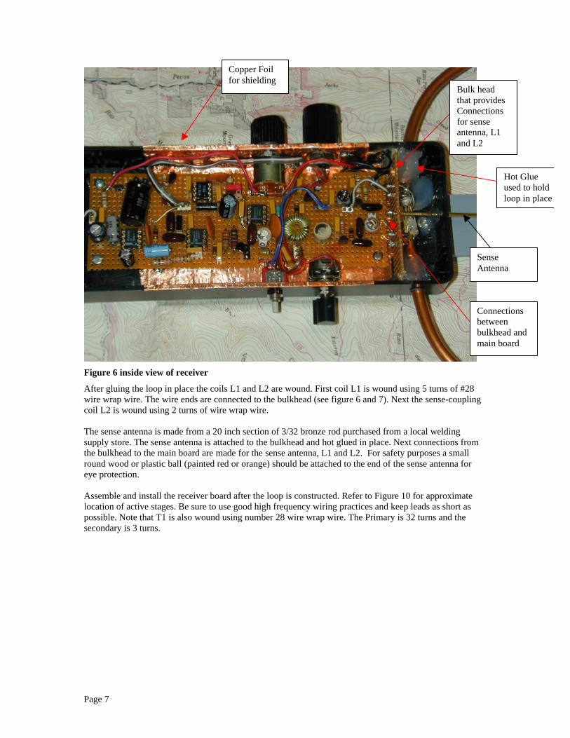
Figure 6 inside view of receiver
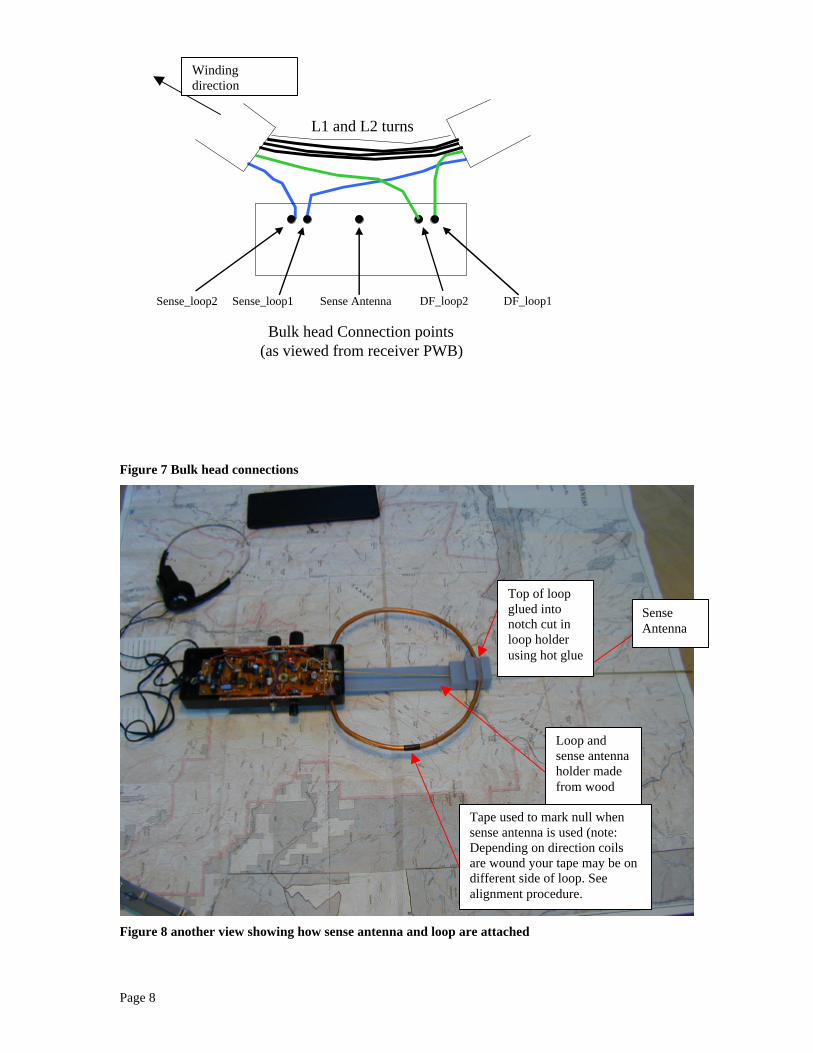
After gluing the loop in place the coils L1 and L2 are wound. First coil L1 is wound using 5 turns of #28wire wrap wire. The wire ends are connected to the bulkhead (see figure 6 and 7). Next the sense-couplingcoil L2 is wound using 2 turns of wire wrap wire.
The sense antenna is made from a 20 inch section of 3/32 bronze rod purchased from a local weldingsupply store. The sense antenna is attached to the bulkhead and hot glued in place. Next connections fromthe bulkhead to the main board are made for the sense antenna, L1 and L2. For safety purposes a smallround wood or plastic ball (painted red or orange) should be attached to the end of the sense antenna foreye protection.
Assemble and install the receiver board after the loop is constructed. Refer to Figure 10 for approximatelocation of active stages. Be sure to use good high frequency wiring practices and keep leads as short aspossible. Note that T1 is also wound using number 28 wire wrap wire. The Primary is 32 turns and thesecondary is 3 turns.
Copper Foilfor shielding
SenseAntenna
Bulk headthat providesConnectionsfor senseantenna, L1and L2
Hot Glueused to holdloop in place
Connectionsbetweenbulkhead andmain board
Page 8
Bulk head Connection points(as viewed from receiver PWB)
DF_loop1DF_loop2Sense AntennaSense_loop1Sense_loop2
L1 and L2 turns
Figure 7 Bulk head connections
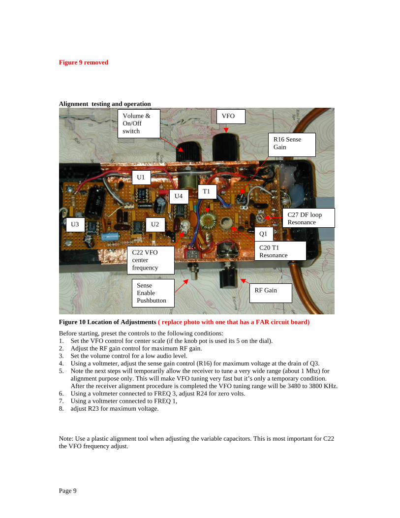
Figure 8 another view showing how sense antenna and loop are attached
SenseAntenna
Top of loopglued intonotch cut inloop holderusing hot glue
Loop andsense antennaholder madefrom wood
Tape used to mark null whensense antenna is used (note:Depending on direction coilsare wound your tape may be ondifferent side of loop. Seealignment procedure.
Windingdirection
Page 9
Figure 9 removed
Alignment testing and operation
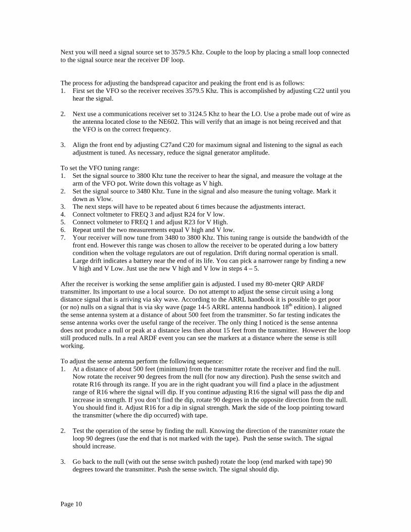
Figure 10 Location of Adjustments ( replace photo with one that has a FAR circuit board)
Before starting, preset the controls to the following conditions:1. Set the VFO control for center scale (if the knob pot is used its 5 on the dial).2. Adjust the RF gain control for maximum RF gain.3. Set the volume control for a low audio level.4. Using a voltmeter, adjust the sense gain control (R16) for maximum voltage at the drain of Q3.5. Note the next steps will temporarily allow the receiver to tune a very wide range (about 1 Mhz) for
alignment purpose only. This will make VFO tuning very fast but it’s only a temporary condition.After the receiver alignment procedure is completed the VFO tuning range will be 3480 to 3800 KHz.
6. Using a voltmeter connected to FREQ 3, adjust R24 for zero volts.7. Using a voltmeter connected to FREQ 1,8. adjust R23 for maximum voltage.
Note: Use a plastic alignment tool when adjusting the variable capacitors. This is most important for C22the VFO frequency adjust.
R16 SenseGain
C27 DF loopResonance
C20 T1Resonance
T1
C22 VFOcenterfrequency
VFOVolume &On/Offswitch
RF GainSenseEnablePushbuttonswitch
Q1
U4
U1
U2U3
Page 10
Next you will need a signal source set to 3579.5 Khz. Couple to the loop by placing a small loop connectedto the signal source near the receiver DF loop.
The process for adjusting the bandspread capacitor and peaking the front end is as follows:1. First set the VFO so the receiver receives 3579.5 Khz. This is accomplished by adjusting C22 until you
hear the signal.
2. Next use a communications receiver set to 3124.5 Khz to hear the LO. Use a probe made out of wire asthe antenna located close to the NE602. This will verify that an image is not being received and thatthe VFO is on the correct frequency.
3. Align the front end by adjusting C27and C20 for maximum signal and listening to the signal as eachadjustment is tuned. As necessary, reduce the signal generator amplitude.
To set the VFO tuning range:1. Set the signal source to 3800 Khz tune the receiver to hear the signal, and measure the voltage at the
arm of the VFO pot. Write down this voltage as V high.2. Set the signal source to 3480 Khz. Tune in the signal and also measure the tuning voltage. Mark it
down as Vlow.3. The next steps will have to be repeated about 6 times because the adjustments interact.4. Connect voltmeter to FREQ 3 and adjust R24 for V low.5. Connect voltmeter to FREQ 1 and adjust R23 for V High.6. Repeat until the two measurements equal V high and V low.7. Your receiver will now tune from 3480 to 3800 Khz. This tuning range is outside the bandwidth of the
front end. However this range was chosen to allow the receiver to be operated during a low batterycondition when the voltage regulators are out of regulation. Drift during normal operation is small.Large drift indicates a battery near the end of its life. You can pick a narrower range by finding a newV high and V Low. Just use the new V high and V low in steps 4 – 5.
After the receiver is working the sense amplifier gain is adjusted. I used my 80-meter QRP ARDFtransmitter. Its important to use a local source. Do not attempt to adjust the sense circuit using a longdistance signal that is arriving via sky wave. According to the ARRL handbook it is possible to get poor(or no) nulls on a signal that is via sky wave (page 14-5 ARRL antenna handbook 18th edition). I alignedthe sense antenna system at a distance of about 500 feet from the transmitter. So far testing indicates thesense antenna works over the useful range of the receiver. The only thing I noticed is the sense antennadoes not produce a null or peak at a distance less then about 15 feet from the transmitter. However the loopstill produced nulls. In a real ARDF event you can see the markers at a distance where the sense is stillworking.
To adjust the sense antenna perform the following sequence:1. At a distance of about 500 feet (minimum) from the transmitter rotate the receiver and find the null.
Now rotate the receiver 90 degrees from the null (for now any direction). Push the sense switch androtate R16 through its range. If you are in the right quadrant you will find a place in the adjustmentrange of R16 where the signal will dip. If you continue adjusting R16 the signal will pass the dip andincrease in strength. If you don’t find the dip, rotate 90 degrees in the opposite direction from the null.You should find it. Adjust R16 for a dip in signal strength. Mark the side of the loop pointing towardthe transmitter (where the dip occurred) with tape.
2. Test the operation of the sense by finding the null. Knowing the direction of the transmitter rotate theloop 90 degrees (use the end that is not marked with the tape). Push the sense switch. The signalshould increase.
3. Go back to the null (with out the sense switch pushed) rotate the loop (end marked with tape) 90degrees toward the transmitter. Push the sense switch. The signal should dip.
Page 11
4. Another simple test is to hold in the sense switch while rotating the receiver. The signal should dipwhen the end marked with tape is pointing toward the transmitter (the dip is 90 degrees offset from thenull obtained with no sense). The signal should peak when the end of the loop with no tape is pointedat the transmitter.
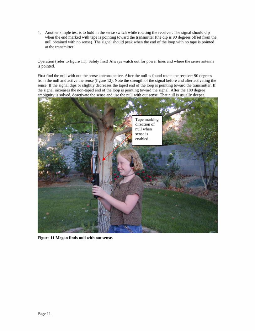
Operation (refer to figure 11). Safety first! Always watch out for power lines and where the sense antennais pointed.
First find the null with out the sense antenna active. After the null is found rotate the receiver 90 degreesfrom the null and active the sense (figure 12). Note the strength of the signal before and after activating thesense. If the signal dips or slightly decreases the taped end of the loop is pointing toward the transmitter. Ifthe signal increases the non-taped end of the loop is pointing toward the signal. After the 180 degreeambiguity is solved, deactivate the sense and use the null with out sense. That null is usually deeper.
Figure 11 Megan finds null with out sense.
Tape markingdirection ofnull whensense isenabled

Page 12
Figure 12 Megan activating sense and notes that the signal nulls
Modifications to receiver since original publicationThe following modifications are “must do” modifications that improve the performance of the radio.
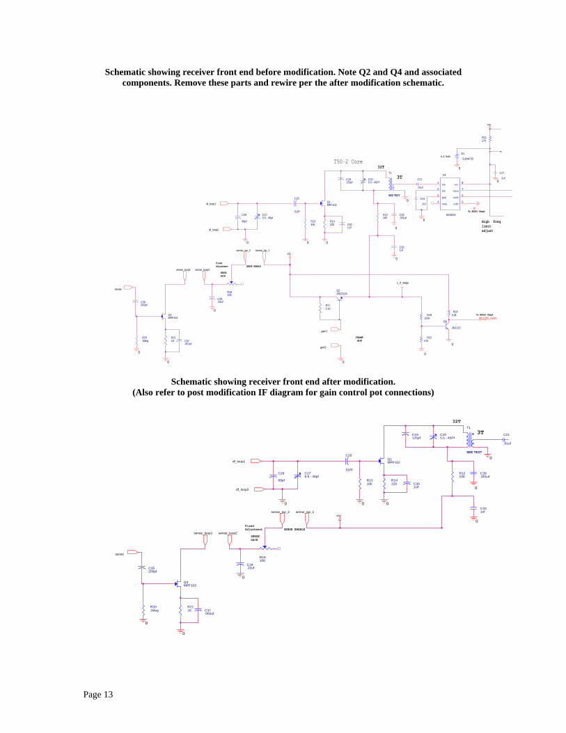
The “Sam Smith” gain control modification.To perform the Sam Smith (N4MAP) gain modification first remove Q2,Q4 and all associated components.Next to get VCC connected to the front end, first connect a shorting Jumper between the collector andemitter pins of Q2. This will put the FET front end in normal operational mode. This stage has enoughdynamic range to handle a 3 watt 80 meter ARDF transmitter.
Next wire the gain pot as shown per the post modification schematic. This modification provides very goodgain control operation. (Note in my version I did not use the 22K resistor, I just connected the bottom of thepot to ground.)
Tape pointing indirection of signal. 180-degree ambiguitysolved.
Page 13
Schematic showing receiver front end before modification. Note Q2 and Q4 and associatedcomponents. Remove these parts and rewire per the after modification schematic.
Schematic showing receiver front end after modification.(Also refer to post modification IF diagram for gain control pot connections)
0
0
vcc
0
v_rf_stage
0
0
vcc
0
0
0
0
0
0
0
0
0
0
IF
MC1350_GAIN
R182.2k
R211K C37
.001uf
R201Meg
R1610K
C35200pf
C34.22uf
Q3MPF102
C25
51Pf
R14220
C29
68pf
C275.5 - 45pf
R19100k
Q1MPF102
T1
SEE TEXT
C301Uf
R1310k
C205.5 - 45Pf
C19125pf
C331uf
R175.1k
Q22N2222A
R12100
C28.001uf
Q4
2N2222
C21
.01uf
R2247k
C24
.1uf
U4
NE602A
1
2
3
4 5
6
7
8ina
inb
gnd
outa outb
oscb
osca
vcc
D1
D1N4735
R11270
C17
.1uf
sense_loop1 sense_loop2
df_loop1
gain1
sense_sw_2
sense
sense_sw_1
df_loop2
gain2
FixedAdjustment
SENSEGAIN
3T
PREAMP GAIN
32T
SENSE ENABLE
T50-2 Core6.2 Volt
To AUDIO Sheet
To AUDIO Sheet
High freq limitadjust
0
0
vcc
0
0
0
0
0
0
0
C37.001uf
R211K
R201Meg
Q3MPF102
C34.22ufC35
200pf
R1610K
C275.5 - 45pf
C29
68pf R14220
C25
51Pf
C301Uf
T1
SEE TEXT
Q1MPF102
C331uf
C19125pf
C205.5 - 45Pf
R1310k
C28.001uf
R12100
C21
.01uf
sense_loop1 sense_loop2
df_loop1
sense_sw_2
sense
sense_sw_1
df_loop2
FixedAdjustment
SENSEGAIN
3T
32T
SENSE ENABLE
Page 14
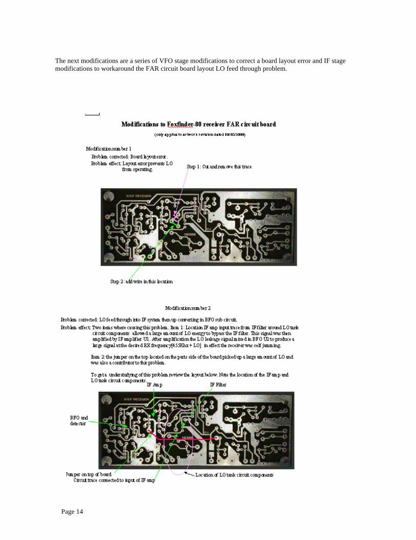
The next modifications are a series of VFO stage modifications to correct a board layout error and IF stagemodifications to workaround the FAR circuit board layout LO feed through problem.

Page 15

Page 16
Sam also noted that he added the capacitor C31 to reduce the IF LO mixing problem. My current version isusing the series trap circuit on the input to the IF. I plan to investigate making the IF stage a tuned amplifierinstead to the wide band version in the schematic. This could be accomplished by using an IF transformer inthe output circuit of the MC1350. This would be the preferred solution to the problem. LO leakage is beingamplified by this stage and mixing with the BFO to produce the offending signal at HF. There is anothersignal that appears around 3640Khz. This is the 8th harmonic of the BFO. Its far enough from the huntfrequency and shouldn’t cause a problem. Additional shielding of the BFO stage and filtering of the VCC tothe BFO stage could be a possible solution in eliminating it.
IF stage before modification
0
0
0
0
0
0
0
0
vcc
MC1350_GAIN
IF
C2
.1uf
L3
150uH
C4
.1uf
C11
.01uf
C9
.1uf
R9
1.5k
R4
22 C1
100uf
U1
MC1350
1
2
3
4 5
6
7
8OUT-
VCC
GND1
IN- AGC
IN+
GND
OUT+
455KHZ
FL1 TK2330-ND
IN
GN
D
OUT
C8
.01uf
R6
470
IFAMP
From RCVR Sheet
From RCVR Sheet

Page 17
IF stage After modification(Note the direct connections for the gain control pot. This was part of the gain control modification.)
0
0
0
0
0
0
0
0
0
0
vcc
0
vcc
00
IF
R1922k
C31
.0015Uf
C38
5-35Pf
L3
150uHC2
.1uf
R9
1.5k
C9
.1ufC11
.01uf
C4
.1uf
L5
150uH
U2
NE602A
1
2
3
4 5
6
7
8ina
inb
gnd
outa outb
oscb
osca
vcc
U1
MC1350
1
2
3
4 5
6
7
8OUT-
VCC
GND1
IN- AGC
IN+
GND
OUT+
C1
100uf
R4
22
455KHZ
FL1 TK2330-ND
IN
GN
D
OUT
C3
.1uf
R6
470
C8
.01uf
pot1
pot3
pot2
IFAMP
BFO&PRODDET
From RCVR Sheet
This is the cap that Sam added in his version.Do not use if the WB8WFK series trap circuitis used.
WB8WFK series trap circuit mod.
Series trapModificationby WB8WFKto reduceeven furtherthe leakagefrom the LOin the circuitboard version
Modificationby Sam Smithto kill thegain of the IFat HF
Page 18
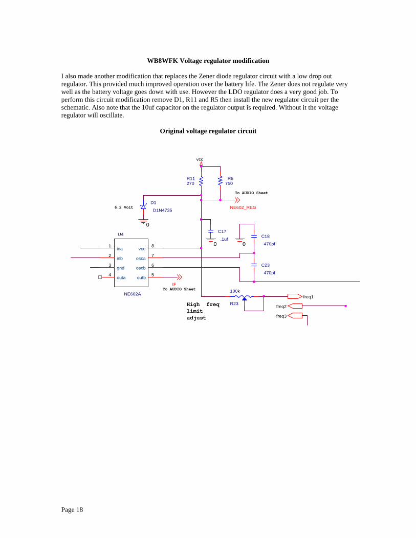
WB8WFK Voltage regulator modification
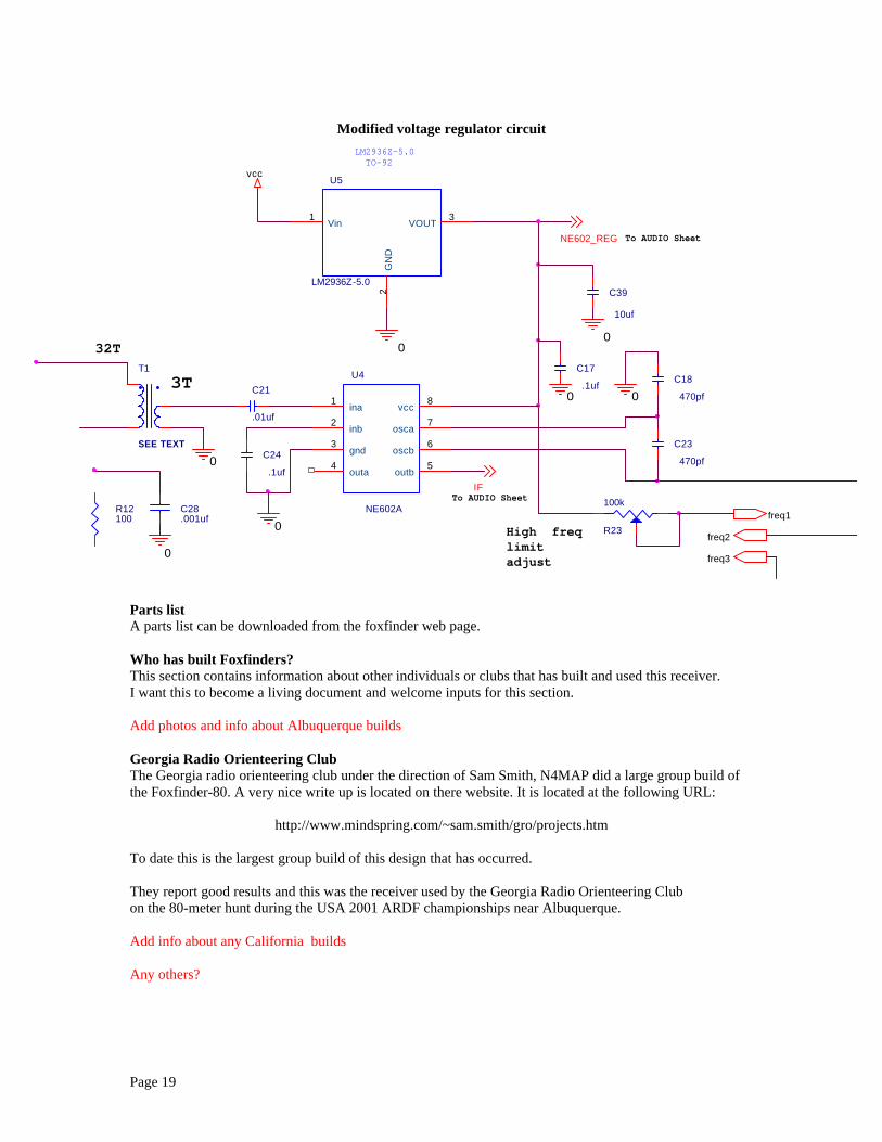
I also made another modification that replaces the Zener diode regulator circuit with a low drop outregulator. This provided much improved operation over the battery life. The Zener does not regulate verywell as the battery voltage goes down with use. However the LDO regulator does a very good job. Toperform this circuit modification remove D1, R11 and R5 then install the new regulator circuit per theschematic. Also note that the 10uf capacitor on the regulator output is required. Without it the voltageregulator will oscillate.
Original voltage regulator circuit
vcc
0
00
IF
NE602_REG
R5750
R23
100k
U4
NE602A
1
2
3
4 5
6
7
8ina
inb
gnd
outa outb
oscb
osca
vcc
R11270
D1
D1N4735
C17
.1ufC18
470pf
C23
470pf
freq1
freq2
freq3
6.2 Volt
To AUDIO Sheet
To AUDIO Sheet
High freq limitadjust
Page 19
Modified voltage regulator circuit
Parts listA parts list can be downloaded from the foxfinder web page.
Who has built Foxfinders?This section contains information about other individuals or clubs that has built and used this receiver.I want this to become a living document and welcome inputs for this section.
Add photos and info about Albuquerque builds
Georgia Radio Orienteering ClubThe Georgia radio orienteering club under the direction of Sam Smith, N4MAP did a large group build ofthe Foxfinder-80. A very nice write up is located on there website. It is located at the following URL:
http://www.mindspring.com/~sam.smith/gro/projects.htm
To date this is the largest group build of this design that has occurred.
They report good results and this was the receiver used by the Georgia Radio Orienteering Clubon the 80-meter hunt during the USA 2001 ARDF championships near Albuquerque.
Add info about any California builds
Any others?
vcc
0
0
0
0
0
0
0
IF
NE602_REG
LM2936Z-5.0TO-92
U5
LM2936Z-5.0
1
2
3Vin
GN
D
VOUT
T1
SEE TEXT
R12100
C28.001uf
R23
100k
C21
.01uf
C24
.1uf
U4
NE602A
1
2
3
4 5
6
7
8ina
inb
gnd
outa outb
oscb
osca
vcc
C17
.1uf
C23
470pf
C18
470pf
C39
10uf
freq1
freq2
freq3
3T
32T
To AUDIO Sheet
To AUDIO Sheet
High freq limitadjust

Page 20