CAUTION - Dexter Axles, All Trailer Parts, Hydrastar, Dexter Parts

1
80 LB.OPL MICRO REVERSING DRYER
DTCH 80 V
The Dexter Company
Fairfield Iowa 52556
641-472-5131 Part number # 8533-051-001
FAX: 641-472-6336 3/05
Service Procedures and Parts Data

2
WARNINGFOR YOUR SAFETY, THE INFORMATION IN THIS MANUAL MUST BE FOLLOWED TO
MINIMIZE THE RISK OF FIRE OR EXPLOSION OR TO PREVENT PROPERTY
DAMEGE, PERSONAL INJURY OR LOSS OF LIFE.
IF YOU SMELL GAS:Do Not try to light any appliace.
Do Not touch or operate any electrical switch.
Do Not use any phone in your building.
Do clear the room, building or area of all occupants.
Do immediately call your gas supplier from a neighbors phone. Follow the gas
suppliers instructions.
Do call the fire department if your gas supplier is not available.
Disconnect power before servicing
WARRANTY REGISTRATION ACTIVATED WHEN
REGISTRATION RECEIVED AT FACTORY.
SEND WARRANTY REGISTRATION AT STARTUP!!!!!!
serial number on rear of dryer
WARNINGDRY ONLY FABRICS WASHED IN WATERTO AVOID THE RISK OF FIRE, INCLUDING SPONTANEOUS COMBUSTIONS,
DO NOT DRY:
- ITEMS CONTAINING FOAM RUBBER. OR ANY SIMILARLY TEXTURED
RUBBER-LIKE MATERIALS.
- ANY ITEMS ON WHICH YOU HAVE USED A CLEANING SOLVENT OR
WHICH CONTAIN FLAMMABLE LIQUIDS OR SOLIDS, SUCH AS NAPTHA,
GASOLINE, OR OTHER OILS OR WAXES.

3
Table of Contents
SECTION 1
Specifications .................................................................................................... page 4 - 5
SECTION 2
Installation & Operation ...................................................................................... page 7-25
Micro Fault Codes ............................................................................................. page 26-27
SECTION 3
Wiring Schematics ............................................................................................. page 28-29
SECTION 4
Service Procedures ........................................................................................... page 30-35
SECTION 5
Trouble Shooting ................................................................................................ page 36-38
SECTION 6
Parts Data ......................................................................................................... page 39-53
SECTION 7
Maintenance ...................................................................................................... page 54

4
Section 1Specifications
Model DTCH80V Reversing
Micro-controlled Industrial Dryer
Capacity Maximum 80 pounds dry weight (36kg)
Cylinder dimensions 36 1/2" (92.71cm) diameter
38" (96.52cm) depth
Cabinet dimensions 38.44" W x 51.13" D x 75.5" H (w/legs)
(97.63cm X 129.86cm X 191.77cm w/legs)
Motors Drive motor - 1/2 HP (.373 Kw)
Blower motor - 1/2 HP (.373 Kw)
Construction Standard trunnion style cylinder support
Air flow 1200 cfm total air flow (33.98M3/min)
Fully perforated tumbler for cross flow air circulation
BTU rating 215,000 BTU input (54,180 kcal)
Natural gas standard, LP kits available separately from P&S
Ignition Direct spark electronic ignition
Exhaust One 8" connection (20.32cm)
.3 StaticPressure Max. at rear of dryer
Gas line connection 1/2" N.P.T. (1.27cm)
Electrical 208-240 Volts, 60 HZ AC, 3 Ph.
15 amp circuit breaker or equivalent.
Micro control 5 Programmable formulas
Temperature Control Sensor
Weight (shipping lbs. / net lbs. ) 693/613 (312.16 kg / 276.12 kg)
Service 3 wire + ground
Colors White & Stainless Steel

12.055"(30.50cm)
Electrical Connection
64.63"(164.15cm)(25.71cm)
12.00" ( 30.48cm)
5.06" (12.86cm)
8.00" (20.32 cm)
10 1/8"
Back
Gas Connection14.00"(35.56cm)
75.13"(190.82cm)
31.1"(79.06cm)
1.375"(3.49cm)Max.3/8"(.952cm) min.
38.44"(97.63cm)
Front
51.13"(129.86cm)
Side
42.38"(107.63cm)
30.90"12.09"
(30.48cm)
(29.26cm)11.52"
(78.48cm)

6
Section 2Installation & Operation
Uncrating1. Remove cardboard and innerpack.
Installation1. All commercial dryer installations must conform with local applicable local codes or in the
absence of local codes, with the National Fuel Gas Code ANSI Z223.1A-1988. Canadian
installations must comply with current standard CAN/CGA-B149(.1 or .2) Installation Code for
Gas Burning Appliances or
Equipment, and local codes if applicable. The appliance, when installed, must be electri-
cally groundedin accordance with the National Electric Code, ANSI/NFPA No. 70-1990, or
when installed in Canada, with Standard CSA C22.1 Canadian Electrical Code Part 1.
2. Installation clearances: This unit may be installed at the following alcove clearances.
1. Left side 0"*
2. Right side0"* *Units may be installed in direct contact with an adjacent dryer,
providing allowance is made for opening upper & lower service doors.
3. Back 18" (certified for 1" clearance; however 18" behind the guard is
recommended to clean, service, & maintain the dryer)
4. Front 48" to allow use of dryer.
5. Top Certification allows 0" clearance at the top from the front back 1".
However, a 1/4" clearance (A) is required to allow opening the upper
service door. A 4" clearance (C) is required at the top, at a depth of 1" to
4" (D) from the front. A 10" clearance (E) is required from the top at all
other points.
6. Floor This unit may be installed upon a combustible floor.

7
Make-up Air. Adequate make-up air must be supplied to replace air exhausted by dryers
on all types of installations. Provide a minimum of 1 1/2 square foot of make-up air opening to
the outside for each dryer. This is a net requirement of effective area. Screens, grills or
louvers which will restrict the flow of air must be considered. Consult the supplier to determine
the free area equivalent for the grill being used.
The source of make-up air should be located sufficiently away from the dryers to allow an even
air flow to the air intakes of all dryers. Multiple openings should be provided.
NOTE: The following considerations must be observed for gas dryer installations where dry
cleaners are installed. The sources of all make-up air and room ventilation air movement to all
dryers must be located away from any dry cleaners. This is necessary so that solvent vapors
will not be drawn into the dryer inlet ducts. Dry cleaner solvent vapors will decompose in
contact with an open flame such as the gas flame present in clothes dryers. The decomposi-
tion products are highly corrosive and will cause damage to the dryer ducts and clothes loads.
NOTE: THE DRYER MUST BE GROUNDED BY A SEPARATE GROUND CONDUCTOR
FROM THE GROUND SCREW ON THE DRYER TO THE NEUTRAL BAR IN THE
SUPPLY BREAKER BOX.
Gas requirementsThe complete gas requirements necessary to operate the dryer satisfactorily are listed on the
serial plate located on the back panel of the dryer. The inlet gas connection to the unit is ̊
inch pipe thread. However, the size of the piping to supply the dryer should be determined by
reference to the Fuel Gas Code and consulting the local gas supplier.
A joint compound resistant to the action of liquefied petroleum gases should be employed in
making pipe connections. A 1/8 inch NPT plugged tapping, accessible for test gage connec-
tion, must be installed immediately upstream of the gas supply connection to the dryer. A drip
tee should be provided in the gas piping supplying the unit to catch dirt and other foreign
articles. All pipe connections should be checked for leakage with soap solution or leak
detector. Never check with an open flame.
Pressure TestingThe dryer and its individual shutoff valve must be disconnected from the gas supply piping
system during any pressure testing of that system at test pressures in excess of ̊ psig. The
dryer must be isolated from the gas supply piping system by closing its individual manual
shutoff valve during any pressure testing of the gas supply piping system at test pressures
equal to or less than 1/2 psig. Max. 1/2 psig on supply side of manual gas valve.
Exhaust InstallationAn 8" diameter exhaust connection is required. Exhausting of the dryer should always be
planned and constructed so that minimum air restrictions occur. Any restriction due to pipe
size or type of installation can cause slow drying time, excessive heat, and lint build up in the
system and the room.

8
NOTE: From an operational standpoint, incorrect or inadequate exhausting can cause
cycling of the high limit thermostat which shuts off the main burners and results in inefficient
drying.
NOTE: Individual exhausting of the dryer is recommended. All heat, moisture, and lint should
be exhausted outside by attaching a pipe of the proper diameter to the dryer adapter collars
and extending it out through an outside wall. This pipe must be very smooth on the inside, as
rough surfaces tend to collect lint which will eventually clog the ducts and prevent the dryer from
exhausting properly. All elbows must be smooth on the inside. All joints must be made so the
exhaust end of one pipe is inside the next one downstream. The addition of an exhaust pipe
tends to reduce the amount of air the blower can exhaust. This does not affect the dryer
operation if held within practical limits. For the most efficient operation, it is recommended
that no more than 20 feet of straight 8" diameter pipe with two right angle elbows be used for
each cylinder. When more than two elbows are used, two feet of straight pipe should be
removed for each additional elbow. No more than four right angle elbows should be used to
exhaust each cylinder. Max. .3 Static Pressure at rear of dryer.
NOTE: If the exhaust pipe passes through a wall, a metal sleeve of slightly larger diameter
should be set in the wall and the exhaust pipe passed through this sleeve. This practice is
required by some local codes and is recommended in all cases to protect the wall. This type
of installation should have a means provided to prevent rain and high winds from entering the
exhaust when the dryer is not in use. A hood with a hinged damper can be used for this
purpose. Another method would be to point the outlet end of the pipe downward to prevent
entrance of wind and rain. In either case, the outlet should be kept clear, by at least 24", of any
objects which would cause air restrictions.
NOTE: Never install a protective screen over the exhaust outlet.
NOTE: When exhausting a dryer straight up through a roof, the overall length of the duct has
the same limits as exhausting through a wall. A rain cap must be placed on top of the exhaust
and must be of such a type as to be free from clogging. The type using a cone shaped “roof”
over the pipe is suitable for this application.
NOTE: Exhausting the dryer into a chimney or under a building is not permitted. In either
case, there is a danger of lint build-up which can be highly combustible.
NOTE: Installation of several dryers where a main discharge duct is necessary, will need the
following considerations for installation. Indivdual 8" ducts from the dryers into the main
discharge duct should be at a 45 degree angle in the direction of discharge air flow.

9
NOTE: A small diameter duct will restrict air flow, a large diameter duct will reduce air
velocity, both contributing to lint build up. An inspection door should be provided for periodic
clean-out of the main duct.
DRYER SHUTDOWNTo render the dryer inoperative turn off the main gas shut-off valve and disconnect power to the
dryer.
DIAMETER TO INCREASE AS SHOWN
NOTE: Never install the 8" ducts at a right angle into the main discharge duct. The following
illustration shows the various round main duct diameters to use with the individual dryer ducts.
The main duct can be rectangular or round, provided adequate air flow is maintained. For
each dryer, the total exhausting (main discharge duct plus duct outlet from the dryer) should not
exceed the equivalent of 20 feet and two elbows. The diameter of the main discharge duct at
the last dryer must be maintained to exhaust end.

10
Controls TransformerThis transformer is mounted in the control box on the back of the dryer and steps a range of
208 to 240 volts down to 24 volts for the controls. There are three terminals on the controls
transformer for the incoming power. The 208 VAC terminal is for 208 to 220 volts and the 240
VAC terminal is for 221 to 240 volts. The control voltage on secondary side is 24 volts.
Electrical requirementsThe electrical power requirements necessary to operate the unit satisfactorily are listed on the
serial plate located on the back panel of each dryer. The electrical connection should be made
to the terminal in the control box on the rear of the unit, using a wire size adequate to handle
the amperage and voltage listed on the serial plate, but never smaller than No. 12 AWGwire. The ground lug must be connected to a good external ground.The schematic and
wiring diagram are located on the belt guard on the back of the machine.
FUSE REQUIREMENTS : 15 amp circuit breaker 3 phase recommended
NOTE: THE DRYER MUST BE GROUNDED BY A SEPARATE GROUND CONDUCTOR
FROM THE GROUND SCREW ON THE DRYER TO THE NEUTRAL BAR IN THE
SUPPLY BREAKER BOX.

11
OPERATING INSTRUCTIONS
To dry a load of items, you must choose one of the five-programmed dry cycles. Each of
these five dry cycles may be modified in two different ways to match your load. Please refer to
the “Permanent Programming” or “Temporary Programming” section of these instructions.
There are two parts to each dry cycle. The first part is the heating time, which is when the
gas valve is cycled on and off according to the temperature setting in the dry cycle program.
The second part is the cool down time, which is after the heating part of the dry cycle, and is
when the cylinder continues to turn, but no heat is applied.
There will always be at least two minutes of cool down time for each dry cycle. The
maximum amount of cool down time is 15 minutes.
During a reversing dry cycle, the tumbler will rotate in one direction for two minutes,
decelerate for four seconds, and then rotate in the opposite direction for two minutes. This
motion will repeat for the duration of the dry cycle.
In the following instruction steps, things that are displayed on the 4-digit numerical display
will be in “quotation marks” and any keys on the dryer controller touch pad that physically need
to be pressed will be in CAPITAL AND BOLD LETTERS.
1) Place your load into the dryer cylinder and close the dryer loading door. Notice that the
dryer controller 4-digit numerical display should show the word “LOAd”. If it does not show
this word, then press and release the STOP touch pad key on the dryer controller twice.
2) Press and release the UP or DOWN arrow touch pad key on the dryer controller to select a
dry cycle.
3) Once the desired dry cycle is selected, press and release the START touch pad key.
After the dryer controller START touch pad key is pressed, the dryer cylinder will start
rotating and the two-digit total dry cycle time, along with a decimal point, will appear on the
dryer controller display.
The time shown on the dryer controller display will count down to the programmed cool
down time. At that time, the display will change from the decimal point and two-digit
number to a letter “C” and two digits.
The letter “C” represents the cool down portion of the dry cycle. The two digits represent
the amount of time remaining in the dry cycle. The two-digit time, shown on the dryer
controller display, will count down to zero.
When the time returns to zero, the dryer controller display will flash the word “donE” and the
end of cycle tone will sound.

12
At that point, the wrinkle free cycle will automatically begin. This cycle will wait two minutes,
if the door is not opened or the STOP touch pad key on the dryer controller is not pressed,
and then rotate the cylinder for 10 seconds and stop. This two minutes of idle time and 10
seconds of tumble time will repeat a total of 10 times, at which time the wrinkle free cycle
stops. The cylinder will not rotate again until a new dry cycle is started.
During the wrinkle free cycle the gas valve will not be operated and there will be no heat
applied to the load. The word “donE” will also continue to flash and do so even after the
wrinkle free cycle is finished. When the dryer loading door is opened, or the STOP touch
pad key is pressed, the word “donE” will change to the word “LOAd” on the dryer controller
display. The dryer will then be ready for another dry cycle.
During the dry cycle, either pressing the STOP touch pad key on the dryer controller or
opening the dryer loading door, will stop the dry cycle and not clear it. If you press the
STOP touch pad key on the controller and then open the dryer loading door the dry cycle
will not be cleared. However, if you open (or open and close) the dryer loading door and
then press the STOP touch pad key on the dryer controller, the present dry cycle will be
cleared and the word “LOAd” will appear on the dryer controller display.

13


16
TEMPORARY PROGRAMMING
The temporary programming mode will allow the change of the stored dry cycle
settings in the dryer controller for one complete dry cycle. After the dry cycle is
complete, the default settings that existed before the temporary change are restored.
The temporary dry cycle can be stopped and cleared at any time during the dry cycle
operation.
To temporarily change a dryer controller cycle, follow the procedures below. Things that are
displayed on the 4-digit numeric display will be in “quotation marks”. Keys on the dryer
controller touch pad that physically need to be pressed will be in CAPITAL AND BOLD
LETTERS.
If, at any time, you want to escape the temporary programming mode while changing the
program settings, you can press the STOP key on the dryer controller touch pad if the 4-digit
numeric display is not flashing. The SELECT/ENTER key on the dryer controller touch pad
can be pressed and released to enter the flashing value shown on the 4-digit numeric display
and allow you to escape.
If you press and release the STOP key on the dryer controller touch pad, when the 4-digit
numeric display is not flashing, the temporary changes to the dry cycle program will be
cancelled. The stored dry cycle settings that existed before the temporary change will then be
restored.
If, at any time, you want to start the temporary dry cycle during the temporary programming
mode, press and release the START key on the dryer controller touch pad if the 4-digit
numeric display is not flashing. The SELECT/ENTER key on the dryer controller touch pad
can be pressed and released to enter the flashing value shown on the 4-digit numeric display
and allow you to start the temporary dry cycle. If you start the temporary dry cycle, the 4-digit
numerical display will change to the total dry time and count down to 0 as the dry cycle
progresses.
PROCEDURE
1) Make sure the dryer is not in a dry cycle. The 4-digit numeric display on the dryer
controller will show “LOAd” when the dryer is not in a dry cycle.
2) Press and release the UP or DOWN arrow keys on the dryer controller touch pad to
chose the dry cycle that you want to change (dry cycle 1 through 5). The dry cycle L.E.D.
will illuminate to indicate which dry cycle you are choosing. If you press either arrow key
and hold it down, the controller will sequence through the five dry cycles.

17
3)Press and release the CYCLE key on the dryer controller touch pad once you have
chosen the dry cycle you want to change. After you press this key, the programming L.E.D.
and the dry time L.E.D. will illuminate. The dry cycle L.E.D. will remain illuminated. The
total dry time will also be displayed on the 4-digit numeric display.
4) Press and release the UP or DOWN arrow keys to change the total dry time. Once
either of the arrow keys is pressed, the dry time L.E.D. and the total dry time on the 4-digit
numeric display will flash. If you press and hold either arrow key down, you will increment
(UP arrow) or decrement (DOWN arrow) through the total dry times available (1 through 60
minutes). This displayed dry time includes the cool down time along with the heated time.
To not change the total dry time, do not press the arrow keys. Go to the next step.
5) Press and release the SELECT/ENTER key. Once this key is pressed and released,
the dry time L.E.D. will switch off, the dry cycle L.E.D. and programming L.E.D. will remain
on, and the temperature L.E.D. will illuminate. The drying temperature will also be shown
on the 4-digit numeric display.
6) Press and release the UP or DOWN arrow keys to change the drying temperature.
Each press and release of the arrow keys will either increase or decrease the temperature
by five degrees Fahrenheit or three degrees Celsius, depending on how your dryer
controller is set up. Once either of the arrow keys is pressed, the temperature L.E.D. and
the drying temperature on the 4-digit numeric display will flash. If you press and hold either
arrow key down, you will increment (UP arrow) or decrement (DOWN arrow) your way
through the available drying temperatures (105O Fahrenheit or 41O Celsius, up to 195O
Fahrenheit or 90O Celsius). If you do not want to change the drying temperature, do not
press the arrow keys. Go to the next step.
7) Press and release the SELECT/ENTER key. Once this key is pressed and released,
the temperature L.E.D. will switch off, the dry cycle L.E.D. and programming L.E.D. will
remain on, and the cool down L.E.D. will illuminate. The cool down time will also be shown
on the 4-digit numeric display.
8) Press and release the UP or DOWN arrow keys to change the cool down time. Once
either of the arrow keys is pressed, the cool down L.E.D. and the cool down time on the 4-
digit numeric display will flash. If you press and hold either arrow key down, you will
increment (UP arrow) or decrement (DOWN arrow) through the cool down times available
(2 through 15 minutes). To not change the cool down time, do not press the arrow keys.
Go to the next step.
9) Press and release the SELECT/ENTER key. Once this key is pressed and released,
the cool down L.E.D. will switch off, the dry cycle L.E.D. and programming L.E.D. will
remain on, and the reversing L.E.D. will illuminate. Either “rEv” (reversing mode) or “nrEv”
(non-reversing mode) will also be shown on the 4-digit numeric display.
18
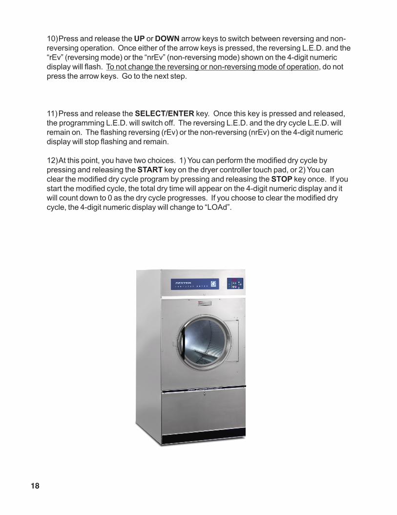
10)Press and release the UP or DOWN arrow keys to switch between reversing and non-
reversing operation. Once either of the arrow keys is pressed, the reversing L.E.D. and the
“rEv” (reversing mode) or the “nrEv” (non-reversing mode) shown on the 4-digit numeric
display will flash. To not change the reversing or non-reversing mode of operation, do not
press the arrow keys. Go to the next step.
11)Press and release the SELECT/ENTER key. Once this key is pressed and released,
the programming L.E.D. will switch off. The reversing L.E.D. and the dry cycle L.E.D. will
remain on. The flashing reversing (rEv) or the non-reversing (nrEv) on the 4-digit numeric
display will stop flashing and remain.
12)At this point, you have two choices. 1) You can perform the modified dry cycle by
pressing and releasing the START key on the dryer controller touch pad, or 2) You can
clear the modified dry cycle program by pressing and releasing the STOP key once. If you
start the modified cycle, the total dry time will appear on the 4-digit numeric display and it
will count down to 0 as the dry cycle progresses. If you choose to clear the modified dry
cycle, the 4-digit numeric display will change to “LOAd”.

19
TEMPORARY PROGRAMMING EXAMPLE
REQUIREMENTS: Dry a load, in reverse mode, with 40 minutes of actual heat at
185 0F and two minutes of cool down.
The following procedure will show you how to temporarily modify the existing dry cycle 5
program for one cycle of drying. It is based on the assumption that the factory defaults have
not been permanently changed. If they have been changed, the steps of this procedure will be
the same, but the values that are displayed will be different. The amount of times that the dryer
controller touch pad UP or DOWN keys must be pressed and released may also be different.
If you want the change to be permanent, go to the “PERMANENT PROGRAMMING” section
of this manual.
PROCEDURE:
1) After the load has been placed in the dryer, press and release the UP or DOWN
touch pad key on the dryer controller until the L.E.D. for dry cycle 5 is illuminated.
2) Press and release the CYCLE key on the dryer controller touch pad. You will see
the number “25” on the dryer controller display. The programming L.E.D. and dry
time L.E.D. will be illuminated.
3) Press and release the UP arrow key on the dryer controller touch pad 17 times so
the display will show a flashing “42”. When the UP arrow touch pad key is pressed
the first time, the number “26” will be flashing on the dryer controller display. Each
number after that will also flash.
4) Now, press and release the SELECT/ENTER touch pad key on the dryer controller.
The number “45” will stop flashing and the dry time L.E.D. will switch off. The dryer
controller display will now show “175”, the temperature L.E.D. will illuminate, and the
programming L.E.D. and dry cycle 5 L.E.D. will remain on.
5) Press and release the UP arrow key on the dryer controller touch pad two times so
the controller display will show a flashing “185”. Each press of the UP arrow key will
increment the temperature by five degrees.

20
6) Now, press and release the SELECT/ENTER touch pad key on the dryer controller.
The number “185” will stop flashing and the temperature L.E.D. will switch off. The
dryer control display will now show a number “2”, the cool down L.E.D. will illuminate,
and the programming L.E.D. and dry cycle 5 L.E.D. will remain on.
7) Press and release the SELECT/ENTER key on the dryer controller touch pad,
since the desired cool down time is two minutes. After you press the SELECT/
ENTER touch pad key on the controller, the cool down L.E.D. will switch off. The
dryer controller display will show “nrEv”, the reversing L.E.D. will illuminate, and the
programming L.E.D. and dry cycle 5 L.E.D. remain on.r controller touch pad, since
the desired cool down time is two minutes. After you press
8) Press and release the UP or DOWN arrow key once. A flashing “rEv” will appear on
the dryer controller display and the reversing L.E.D. will start to flash. Each press
and release of either arrow key will toggle between the reversing mode (“rEv”) and
non-reversing mode (“nrEv”).
9) Press and release the SELECT/ENTER key. Once this key is pressed and
released, the programming L.E.D. and the reversing L.E.D. will switch off. The dry
cycle 5 L.E.D. will remain on. The flashing “rEv” will stop flashing and remain on.
You are now ready to start the new dry cycle. This new dry cycle will be in effect for
one dry cycle only. After the dry cycle is done, or if the STOP touch pad key on the
dryer controller is pressed and released twice, consecutively, the cycle 5 program
will revert to the factory default settings.
If you press the START touch pad key on the dryer controller, the controller display
will change from “rEv” to the number “42” and dry cycle 5 will b

21
PERMANENT PROGRAMMING
The permanent programming mode will allow the change of the stored dry cycle settings in the
dryer controller until the operator physically changes them again. The factory default settings
can be restored in the dryer controller by pressing the default settings pushbutton on the back
(component) side of the dryer controller circuit board. It is labeled and located on the upper
right side of the printed circuit board, as you face the component side of the board. It must be
pressed and held down for at least three seconds.
To permanently change a dryer controller cycle, follow the procedure below. Things that are
displayed on the 4-digit numeric display will be in “quotation marks”. Keys on the touch pad
that physically need to be pressed will be in CAPITAL AND BOLD LETTERS.
If, at any time, you want to escape the permanent programming mode while changing the
settings, you can press and release the STOP key on the dryer controller touch pad if the 4-
digit numeric display is not flashing. The SELECT/ENTER key on the dryer controller touch
pad can be pressed and released to enter the flashing value shown on the 4-digit numeric
display and allow you to escape.
___________________________________________________________________
PROCEDURE
1) Make sure the dryer is not in a dry cycle. The 4-digit numeric display on the dryer
controller will show “LOAd” when the dryer is not in a dry cycle.
2) Press and release the PROG key on the dryer controller touch pad.
3) Press and release the UP arrow key on the dryer controller touch pad. The
programming L.E.D. will illuminate and the 4-digit numeric display on the dryer controller
will change to “Prog”.
4) Press and release the UP or DOWN arrow keys to choose the dry cycle you want to
change (dry cycle 1 through 5). The dry cycle L.E.D. will illuminate to indicate which dry
cycle you are choosing. If you press either arrow key and hold it down, the controller will
sequence through the five dry cycles.
5) Press and release the SELECT/ENTER key once you have chosen the dry cycle you
want to change. After you press this key, the dry time L.E.D. will illuminate. The dry cycle
L.E.D. and the programming L.E.D. will remain illuminated. The total dry time will also be
displayed on the 4-digit numeric display.
6) Press and release the UP or DOWN arrow keys to change the total cycle time. Once
either of the arrow keys is pressed, the dry time L.E.D. and the total dry time on the 4-digit
numeric display will flash. If you press and hold either arrow key down, you will increment
(UP arrow) or decrement (DOWN arrow) through the total dry times available (1 through 60
minutes). This displayed dry time includes the cool down time along with the heated time.
To not change the total dry time, do not press the arrow keys. Go to the next step.

22
7) Press and release the SELECT/ENTER key. Once this key is pressed and released,
the dry time L.E.D. will switch off, the dry cycle L.E.D. and programming L.E.D. will remain
on, and the temperature L.E.D. will illuminate. The drying temperature will also be shown
on the 4-digit numeric display.
8) Press and release the UP or DOWN arrow keys to change the drying temperature.
Each press and release of the arrow keys will either increase or decrease the temperature
by five degrees Fahrenheit or three degrees Celsius, depending on how your dryer
controller is set up. Once either of the arrow keys is pressed, the temperature L.E.D. and
the drying temperature on the 4-digit numeric display will flash. If you press and hold either
arrow key down, you will increment (UP arrow) or decrement (DOWN arrow) your way
through the available drying temperatures (105O Fahrenheit or 41O Celsius, up to 195O
Fahrenheit or 90O Celsius). If you do not want to change the drying temperature, do not
press the arrow keys. Go to the next step.
9) Press and release the SELECT/ENTER key. Once this key is pressed and released,
the temperature L.E.D. will switch off, the dry cycle L.E.D. and programming L.E.D. will
remain on, and the cool down L.E.D. will illuminate. The cool down time will also be shown
on the 4-digit numeric display.
10)Press and release the UP or DOWN arrow keys to change the cool down time. Once
either of the arrow keys is pressed, the cool down L.E.D. and the cool down time on the 4-
digit numeric display will flash. If you press and hold either arrow key down, you will
increment (UP arrow) or decrement (DOWN arrow) through the cool down times available
(2 through 15 minutes). To not change the cool down time, do not press the arrow keys.
Go to the next step.
11)Press and release the SELECT/ENTER key. Once this key is pressed and released,
the cool down L.E.D. will switch off, the dry cycle L.E.D. and programming L.E.D. will
remain on, and the reversing L.E.D. will illuminate. Either “rEv” (reversing mode) or “nrEv”
(non-reversing mode) will also be shown on the 4-digit numeric display.

23
12)Press and release the UP or DOWN arrow keys to switch between reversing and non-
reversing operation. Once either of the arrow keys is pressed, the reversing L.E.D. and the
“rEv” (reversing mode) or the “nrEv” (non-reversing mode) shown on the 4-digit numeric
display will flash. To not change the reversing or non-reversing mode of operation, do not
press the arrow keys. Go to the next step.
13)Press and release the SELECT/ENTER key. Once this key is pressed and released,
the reversing L.E.D. will switch off, the dry cycle L.E.D. and programming L.E.D. will remain
on. The 4-digit numeric display will change to “Prog”.
14)Press and release the STOP key to save the cycle program and escape the
programming mode. If you want to change the same dry cycle program again, press the
SELECT/ENTER key and continue at step 6 of this procedure. If you want to modify
another dry cycle program, go to step 4 of this procedure and continue.
15)If you pressed the STOP key to escape the programming mode, you may now start the
dry cycle by pressing the START key.

24
PERMANENT PROGRAMMING EXAMPLE
REQUIREMENTS: Dry a load, in reverse mode, with 50 minutes of actual heat at
195o F and three minutes of cool down.
The following procedure will show you how to permanently modify the existing dry cycle 5
program for one cycle of drying. It is based on the assumption that the factory defaults have
not been permanently changed. If they have been changed, the steps of this procedure will be
the same, but the values that are displayed will be different. The amount of times that the dryer
controller touch pad UP or DOWN keys must be pressed and released may also be different.
If you want the change to be temporary (for only one dry cycle), go to the “TEMPORARY
PROGRAMMING” section of this manual.
PROCEDURE:
1. After the load has been placed in the dryer, press and release the UP or DOWN touch pad
key on the dryer controller until the L.E.D. for dry cycle 5 is illuminated.
2. Press and release the PROG touch pad key on the dryer controller. The dryer controller
display will not change.
3. Immediately, press and release the UP arrow key on the dryer controller touch pad. The
controller display will change from “LOAd” to “Prog”. You have now entered the permanent
programming mode. The dry cycle 5 L.E.D. will remain on and the programming L.E.D. will
illuminate.
4. Press and release the SELECT/ENTER touch pad key once. The dry cycle 5 L.E.D. and
programming L.E.D. will remain on and the dry time L.E.D. will illuminate. The dryer
controller will also show the number “25”.
5. Press the UP arrow touch pad key 28 times until the dryer controller display shows the
number “53”.
6. Press and release the SELECT/ENTER touch pad key once. The dry cycle 5 L.E.D. and
programming L.E.D. will remain on and the dry time L.E.D. will switch off. The temperature
L.E.D. will illuminate and the dryer controller display will show the number “175”.

25
7. Press and release the UP arrow touch pad key four times until the dryer controller display
shows the number “195”.
8. Press and release the SELECT/ENTER touch pad key. The dry cycle 5 L.E.D. and the
programming L.E.D. will remain on and the temperature L.E.D. will switch off. The cool
down L.E.D. will illuminate and the dryer controller display will show the number “2”.
9. Press and release the UP arrow touch pad key once so the dryer controller display shows
the number “3”.
10.Press and release the SELECT/ENTER touch pad key. The dry cycle 5 L.E.D. and the
programming L.E.D. will remain on and the cool down L.E.D. will switch off. The reversing
L.E.D. will illuminate and the dryer controller display will show “nrEv”.
11. Press and release the UP or DOWN arrow key once. A blinking “rEv” will appear on the
dryer controller display and the reversing L.E.D. will start to blink. Each press and release
of either arrow key will toggle between the reversing mode (“rEv”) and non-reversing mode
(“nrEv”).
12.Press and release the SELECT/ENTER key. Once this key is pressed and released, the
reversing L.E.D. will switch off. The programming L.E.D. and the dry cycle 5 L.E.D. will
remain on. The flashing “rEv” will be replaced by the word “Prog”.
13.Press and release the STOP touch pad key. The dry cycle 5 L.E.D. will remain on and the
programming L.E.D. will switch off. The dryer controller display will change to the word
“LOAd”.
The dryer is now ready for the new modified dry cycle to start. This modified dry cycle 5
program will remain in the dryer controller memory until the default settings push button is
pressed. This default settings push button is located on the component side of the dryer
controller printed circuit board in the upper right corner.

26
Fault Diagnostic IndicatorsFault # Fault Description Action
F1 Shorted thermostat sensor. Stop dryer, flash F1 on display.
F2 Open thermostat sensor. Stop dryer, flash F2 on display.
F3 EEPROM corrupted. Stop dryer, flash F3 on display.
F4 Gas valve circuit not operating. Store F4 fault in memory for later
recall. Does not stop the dryer.
(When temperature does not rise after 5 minutes of operation.)
F5 Gas valve circuit active always. Continue to operate dryer,
flashF5odisplay. After
door is open, flash F5 on display.
(When temperature rises to 25 degrees above the temperature setting.)
The above code faults are displayed on the display.
The F4 fault can be recalled by pushing and holding [ENTER] then push [STOP].
If there has been a F4 fault, the message F4 will be displayed.
The F4 will remain while the switches are held plus for 2 seconds after one or both
are released. Once viewed, the F4 fault is cleared. If there has been no F4 fault
the display will be blank.
There are two jumpers and one push button on the component side of the dryer controller
printed circuit board.
The jumper located roughly in the middle of the circuit board controls whether the controller
display shows and operates in the Fahrenheit or Celsius mode. This jumper is labeled
as TEMP SELECT and has three pins. The top and middle pins are for Celsius and the
bottom and middle pins are for Fahrenheit, which is indicated by the letter C for Celsius
and the letter F for Fahrenheit.
The other jumper, located in the middle of the right side of the component side of the dryer
controller circuit board, is used for choosing either a reversing or non-reversing type of
dryer. This jumper is labeled as REV and NON-REV. This jumper must be in the reversing
position, which are the top and middle pins. If the jumper is in the non-reversing position,
the dryer will not reverse direction.
The push button, which is located in the upper right side of the component side of the dryer
controller circuit board, is used to reset all five of the dry cycles to the factory default
settings. It is labeled as DEFAULT SETTINGS. Even the dry cycles that have been
modified using the permanent programming procedure will be changed back to the factory
default settings when using this push button. This push button must be pressed and held
for at least three seconds with power applied to the dryer controller circuit board.
Micro PCB adjustments at rear of PCB
WARNING - If an F5 fault occurs, turn off the gas at the gas valve in the Upper Ser-
vice area of the dryer. Allow the dryer to operate with the gas off for a minimum of
2 minutes (cool down) beforestopping the dryer.

27
REVERSING DRYER CONTROLLER FACTORY
DEFAULT PROGRAM SETTINGS
DRY
CYCLE
DRYER
DIRECTION
COOL
DOWNTIME
(MINUTES)
TOTAL
CYCLETIME
(MINUTES)
DRYING
TEMPERATURE(0F) (0C)
DRYER LOAD
1 REV. 5 35 180 82Towels, pads,
heavy cotton
2 REV. 2 20 170 77Sheets, blended
materials
3 REV. 5 25 180 82Cotton
4 NON-REV. 2 20 130 54Syntheticmaterials
5 NON-REV. 2 25 175 79Blended materials
REVERSING DRYER FAULT CODES
FAULT#FAULT
DESCRIPTIONACTION
F1Shorted thermostat
sensor.
Dryer stops and “F1” flashes on the 4-digit display. When
short circuit on sensor input is removed, “LOAd” appears
on the 4-digit display and the remaining dry time is reset.
F2Open thermostat
sensor.
Dryer stops and “F2” flashes on the 4-digit display. Whena good sensor is connected to sensor input, “LOAd”
appears on the 4-digit display and the remaining dry time
is reset.
F3 EEPROM corrupted.
Dryer will not start and “F3” appears on the 4-digit
display. The power to the dryer must be cycled to reset
the controller. Fault should only occur when starting a dry
cycle.
F4 Gas valve on fault.
The drying temperature did not increase 1O
F. in 5 minutes.“F4” will flash on the display and the dry cycle will finish
without calling for heat (energizing gas valve). The power
to the dryer must be cycled to reset the controller.
F5 Temperature fault.
The drying temperature is at least 25OF. above the
temperature setting. “F5” will flash on the 4-digit display
and the dry cycle will finish without calling for heat(energizing the gas valve). The power to the dryer must
be cycled to reset the controller.

28

29

Section 4Service Procedures
Clothes Door Removal1. The clothes door may be removed from the hinge bracket by unscrewing and removing the
allen head pivot screw located at the door upper hinge point.
2. Next lean the door out of the top of the hinge bracket and lift the door from the bottom hinge
pin.
Clothes Door Latch Adjustment1. Loosen the lock nut on the latching stud. It is located directly behind the door handle.
2. Open the loading door.
3. Screw the door catch stud in or out as necessary and then retighten the lock nut.
Installation of Clothes Door Window & Gasket1. Remove the loading door.
2. Place the clothes door, with its face down, on a solid surface.
Note: Prewarming the gasket under a heat lamp makes the installation much easier.
3. Put the door glass gasket on the loading door with the ridges in the wide side up. Locate
the seam at the door latching stud.
NOTE: The gasket has one narrow opening on one side and a wide opening on the other.
The narrow side mounts to the door. The wide side holds the glass. The wide side has ridges
on one interior lip. This ridged side should go up with the door laying face down.
4. Coat the inside and outside of the gasket with rubber lubricant or liquid soap.
5. Slide the glass into the middle of the gasket with half of the glass above the door and half
below the door.
6. While pressing on the glass, use a modified screwdriver (grind the end off so that it tis
round and put a slight bend in it) and run it around half of the glass.
7. With half of the glass installed, turn the door over and repeat step 6.
8. Insert the modified screwdriver at the 6 o’clock position and pry the glass up enough to
install the door glass support spacer (small diameter rubber tube).
Door Switch Removal & Installation1. The door switch is located directly behind the hinge plate of the loading door assembly.
Open the door for access to the switch area. Remove the two screws holding the switch
box cover in position. This will allow the removal of the cover and the switch actuator plate.
2. The entire switch box can now be pulled from the front panel opening, creating access to
the door switch mounting screws.
3. Remove these two mounting screws and twin nut which frees the door switch and insulating
shield. Remove wires.
4. When installing the door switch make certain the insulating shield is reassembled
5. The actuator plate and switch box cover should be assembled as illustrated in the parts
section of the book.

Door Switch Operation & Testing1. The normally open door switch must be closed (0 ohms resistance) for the motor and heat
circuits to operate. When the door is opened, the door switch breaks the 24 volt control
circuit.
Door Switch Adjustment1. Remove the two switch box cover screws.
2. Remove the switch cover and actuator plate.
3. Pull the entire switch box out from the opening in the front panel.
4. Loosen the bottom door switch mounting screw.
5. A slotted mounting allows the switch to slide in or out for adjustment.
High Limit Thermostat Locations & FunctionsA. Burner Housing- This hi-limit is located on the left side of the burner housing.
1. The thermostat opens the circuit to the main burners in the event of malfunction in the
gas control area or temperature control. This thermostat will open quickly if there is a
significant loss of air flow over the burner area.
2. It is covered by a guard and is held in place by two screws. There are spacers between
the thermostat and bracket which must be used to give proper operation.
B. Manual Resettable Over Temperature Safety Thermostat- The second hi-limit thermo
stat is located outside he rear exhaust opening mounted on back panel of the machine.
1. The manually resettable thermostat limits the operating temperature a dryer can reach
should some abnormal situation occur.
2. Should the thermostat be tripped, the dryer will cease to heat until the thermostat is
reset. Once the dryer cools, the thermostat may be reset by inserting a pencil or stick
through the opening in the thermostat cover and pushing the button in.
Pressure Regulator AdjustmentUse the following procedure whenever it is necessary to check the pressure regulator setting.
NOTE: Any adjustment of the pressure regulator must be made with a manometer
attached at the plug in the main burner manifold.
1. Shut off the gas supply to the dryer.
2. Remove the 1/8" pipe plug from the end of the main burner manifold.
3. Attach a manometer to the manifold end.
4. Remove the pressure regulator cover screw on the gas valve.
5. Open the shut-off valve, and operate the dryer.
6. Adjust the pressure for a manometer reading of 3.5" water column gas pressure.
(11.0" forL.P.)
NOTE: The main burners must be operating when adjusting the pressure regulator.
7. Shut off the gas supply to the dryer. Remove the manometer and install the 1/8" pipe plug
in the manifold.
8. Open the shut-off valve, start the dryer, and check for gas leaks while the burners are
ignited.

32
panel may be removed with the door left in place, although it is much heavier and more
awkward to do so.)
NOTE: Always remove power from the machine before changing drive belts or
working with the drive and fan system.
Final Drive Belt ReplacementTo replace the final drive belt turn the cylinder slowly by hand and work the belt off of the large
pulley.
Motor Drive Belt Replacement
To replace the motor drive belt the final drive belt should be removed as above. Next turn the
intermediate drive pulley and work the belt off of it similarly to the above belt.
Blower Impeller RemovalRemove the lint hood that is located inside the lower service door. Take notice of the locationof the impeller location on the shaft. Remove the two set screws that hold the motor to theshaft.
Air Switch Removal & AdjustmentThe air switch assembly is part of the ignition safety circuit and insures that the burners don’t
operate unless there is air flow. If this doesn’t happen ignition will not occur. The air switch
assembly is mounted on the right rear of the back panel at about half way up.
Electronic Ignition ModuleThis machine uses an electronic spark ignition system to directly light the burners.
1. The electronic ignition module (gray box) is located inside the upper access door in the
control box.
2. The red wire from the transformer, thru the 1.5 amp fuse and into the module supplies the
24 volts required to operate the entire direct ignition system.
3. The black colored hi-voltage wire (spark plug type) plugs onto the post connector on the
module, and the multi-wire plug fits into the side of the module.
Spark Electrode
Assembly-Function1. The spark electrode and sensing electrodes are located directly over the burners inside the
burner housing.
2. The electrode with the black hi-voltage wire conducts the spark to the center grounding
probe, directly over the burner. The gap between these two areas should be 1/8". The
distance from the electrode to the burner assembly should be 3/8"
3. The electrode with the black sensing wire detects ignition and monitors flame by signaling
the module.
Front Panel RemovalTo remove the front panel, first remove the loading door from the panel. Then remove the two
left side screws and the four right side screws. The trim does not have to be removed. (The

33
Spark Electrode Assembly-Removal1. Remove electrode cover and disconnect wires to electrodes.
2. Remove two screws to detach electrode assembly.
NOTE: Proper grounding of the ignition system (yellow wires) is very critical for
proper ignition sequence.
Ignition System - Function & SequenceDuring normal dryer operation, the following occurs:
1. The dryer thermostat calls for heat.
2. If the drive motor is running, the motor safety circuit provides power to the hi-limit thermo
stat, air damper switch, and cycling thermostat in that order. If the thermostat senses that
the temperature is low enough to require the heat should be on a circuit is closed allowing
power to the ignition module (gray box). After approximately 10 seconds of purge time
power is
appliedtopen the
gas valve and at the
same time sparking
occurs at the
ignition electrode.
3. Once the flame is
established, the
sensing electrode
detects the pres
ence of flame and
the sparking stops.
4. If for any reason the
flame is not estab
lished in a period of
10 seconds, the gray
box shuts down the
sparking and closes
the gas valve which
is now in “ Safety
Lock-Out”. Normally
the 10 seconds “Trial
For Ignition” period
is more than ample
to establish and
prove flame.

34
5. If the flame is shut down or blown out during operation, the ignitor will
immediately go into “Trial For Ignition” again for 10 seconds.
6. However, if during any 10 second “Trial for Ignition”, the flame is not estab lished, the
ignition system goes into “Safety Lock-Out” and will not reactivate the “Trial for Ignition” until
there is a current interruption for a period of 15 seconds. This interruption can be provided
by opening the dryer loading door and allowing the machine to come to a complete stop for
15 seconds.
Ignition System Checkout
1. If flame is present during the “Trial For Ignition” period but the system shuts down, there
may be an improper ground. The entire ignition system is grounded together including
the electrode assembly, the electrode mounting bracket, the burners and the burner
bracket. Shutdown can also occur if for some reason the system isn’t sensing the flame.
Check the sensor for damage and check the connections of the sensor lead.
2. If there is no spark or intermittent spark, check black hi-voltage lead wire for damage or
cracks ininsulation. (This lead wire must not be taped or connected to any metal
edges along its length to prevent pinching and arcing. Also, do not bundle this
wire with other wires.)
NOTE: Spark gap and electrode location are important. If the electrode is damaged or
mounting is changedthe spark gap may not be correct for ignition to occur. Check for cracks in
the ceramic insulator. Replace electrode assembly if necessary. Also check for carbon or
foreign material on the electrodes and clean if necessary.
Gas Valve & Manifold Removal1. Disconnect union at gas valve and disconnect wires from gas valve operator coils.
2. Remove right manifold mounting bracket screws and slide manifold to remove from left
bracket.
Main Burner Orifice Removal1. Remove manifold and gas valve assembly as above.
2. Using an open end wrench, remove orifices from manifold.
Main Burner Removal
Remove manifold & gas valve assembly as previously discussed. Remove the screw securing
the front of the burner to the support bracket. The burner may now be removed.
Cylinder Pulley RemovalRemove nut holding pulley to cylinder shaft. Pull pulley straight off of shaft. Do not lose the
tolerance ring that grips the shaft.
Intermediate Pulley RemovalThe intermediate pulley can be removed by removing the snap ring holding the pulley to the
tension arms.

35
UPPER & LOWER Tension Arm Assembly RemovalThe tension arm assembly may be removed by removing the snap ring that holds it to the
tension arm support assembly pin. If it is necessary the arm assembly is replaced as a
complete unit .
UPPER & LOWER Tension Arm Support Assembly AdjustmentThe tension arm support assembly may be adjusted for alignment of the intermediate pulley
and also to align the belts. The three outer nuts allow the alignment of the pin to be adjusted by
pivoting the assembly on the center bolt. The center bolt can be screwed in to allow bringing
the complete assembly farther back if necessary for belt alignment.
Cylinder Removal
Adjustment of Cylinder Assembly1. Loosen the two top adjusting bolts and two bottom adjusting nuts and lock nuts holding the
bearing housing to the drive plate.
2. Loosen the four mounting bolts on the side channels.
3. Open the clothes door and insert a ˚” thick shim at the 3 and 9 o’clock positions and a 1/
4" thick shim at the 6 o’clock position.
4. Tighten the two bottom adjusting nuts and tighten locking nuts.
5. Tighten the bottom right mounting bolt, then the top left mounting bolt. Tighten the
remaining two bolts. (Shim where and if necessary.)
6. Tighten the two top adjusting bolts.
7. Remove all the shims from between the front panel flange and cylinder
(3,6,9 and 12 o’clock).
8. Spin the cylinder to check for rubbing baffles, pressing down hard while rotating.
If rubbing is detected, repeat procedure paying particular attention to placement of shims
between bearing housing and side channels.
Bearing Housing RemovalAfter removing cylinder as previously outlined, simply unbolt the bearing housing and remove.

36
Section 5Trouble Shooting
Symptom Probable Cause Suggested Remedy
Tumbler does not turn Drive belts Check both drive belts
Drive motor Check capacitor and motor
Door switch Check door switch contacts and adjustment
Micro control Check that LED's are lit and green start key
pushed
Motor Relay Check motor relay coils (24v) and contacts.
Tumbler turns but
no spark at burner
Temperature Check for selected temperature in formula .
Spark Electrode Check electrode for damage to electrode
or mounting
Temperature Check by plugging in good sensor
sensor
Ignition Check for 24 V out of transformer
transformer to ignition control
Ignition control Try another control
Air flow switch Check for circuit through air flow switch
Hi-limit Check hi-limit
Over-temp Check by inserting pencil eraser side thru
(Manual Reset) hole and push to reset
Gas supply No gas can cause system lockout check
for W.C. of more than 3.5 W.C.

37
Tumbler turns Gas supply Make sure gas supply is working
ignition sparks
no flame
Gas pressure Make manometer check of gas pressure
for 3 .5" W.C. or more at supply side
Spark electrode Check electrode for damage to electrode
or mounting
Gas valve Check coil continuity,replace valve if bad
Slow drying Thermostat What is temperature set at on control
Air flow Restrictions follow installation guidelines
for static back pressure and make up air
Lint screen Clean screen
Exhaust Check complete exhaust system for
excessive back pressure in the duct work.
No more than .3 static pressure, at rear
outlet
Makeup air Check for adequate makeup air
(1.5 sq. Ft.)
Temp sensor Clean or replace sensor if necessary
Gas Check gas pressure at burner
( 3.5"W.C.) while burning
Blower Impeller
& Motor Check impeller for operation and
check mounting set screw

38
Section 6Parts Data
CABINET GROUP
Key Part Number Description Qty.
* 9960-256-021 Door Assy., Loading Complete-Wht ............................................... 1
* 9960-256-025 Door Assy., Loading Complete-SS................................................. 1
1 9960-255-007 Door Assy.ONLY, Loading-SS ........................................................ 1
2 9982-280-002 Plate Assy., Hinge (Wht) ............................................................... 1
2 9982-280-011 Plate Assy., Hinge (SS) ................................................................. 1
* 9545-012-015 Screw, Hinge to Door 10-32 x 3/8" ................................................. 4
* 8640-413-002 Nut, Hinge to Door #10-32 UNF ..................................................... 4
3 9212-002-003 Glass, Door ................................................................................... 1
4 9206-164-009 Gasket, Glass ............................................................................... 1
* 9548-117-000 Support, Door Glass (inside gasket) .............................................. 1
5 9206-420-002 Gasket, Outer Rim ........................................................................ 1
6 9244-082-001 Handle, Loading Door .................................................................... 1
* 9545-018-017 Screw, Handle 1/4"-13 x 1 1/4" ...................................................... 2
* 9531-033-001 Stud, Door Catch ........................................................................... 1
* 8640-413-001 Nut, Hex ........................................................................................ 1
* 8640-413-003 Nut , Acorn # 10-32........................................................................ 1
* 9086-015-002 Catch, Loading Door ...................................................................... 1
* 8638-190-009 Pop Rivet for mtg.catch ................................................................. 2
7 9989-460-003 Panel Assy., Front- white ............................................................... 1
7 9989-460-001 Panel Assy., Front- S. Steel .......................................................... 1
* 9277-049-001 Insulation Front Panel top ............................................................. 1
* 9277-049-002 Insulation Front Panel bottom ....................................................... 1
8 9108-100-004 Door, Upper Service-S.S ................................................................ 1
8 9108-100-006 Door, Upper Service-White ............................................................. 1
9 9578-090-002 Trim, Door-Upper Service ............................................................... 1
* 9491-007-002 Rivet- Semitubular ......................................................................... 4
* 6292-006-006 Key ( only ) (FJWCC) .................................................................... 1
10 8650-006-003 Lock w/ nut, Upper Service Door .................................................... 1
* 9206-176-000 Gasket Spacer ............................................................................... 3
* 8638-211-001 Rivet, Drive..................................................................................... 2
* 8641-581-005 Washer, Flat 3/16" ......................................................................... 2
* 9548-243-002 Support, Upper Door ...................................................................... 1
* 8502-617-001 Label "Made In USA"................................................................. 1
11 9412-127-001 Nameplate, Industrial Dryer ........................................................... 1
12 9545-008-020 Screw, Chrome 10AB x 3/4" .......................................................... 10
* 8641-582-019 Lockwasher # 10 ........................................................................... 10
* 8640-399-001 Nut, Spring U type 10Z .................................................................. 6
13 9544-047-002 Strap, Hinge (White) ...................................................................... 1
13 9544-047-007 Strap, Hinge (Gray) ........................................................................ 1
* 9545-012-003 Screw, Hinge to Panel 10T-32 x 1/2" .............................................. 4
14 9545-052-001 Screw, Door to Hinge Strap (special) ............................................. 1
* 8641-436-003 Washer, Fiber/ Plastic ................................................................... 1
* Not Illustrated

39
2
14 & 13
3
7
4
11
1
6
9
12
20
5
15
23
8
10

40
20
CABINET GROUP (continued)
Key Part Number Description Qty.
15 9960-281-001 Door Ass’y, Lower Service-SS ....................................................... 1
15 9960-281-003 Door Ass’y, Lower Service-White ................................................... 1
16 9578-088-001 Trim, Door - Lower Service ............................................................. 1
* 9435-016-003 Overlay-Trim Lower service door .................................................... 1
17 9545-008-021 Screw,Pn Hd Cr., #10Bx3/8 ........................................................... 5
* 9277-050-002 Insulation Lower Service Door ....................................................... 1
18 9578-084-002 Trim, Kick- Lower Service Door ...................................................... 1
19 9545-008-010 Screw, Tr Hd Cr-#10x1/2 Blk.......................................................... 3
20 9244-084-001 Handle Lower Service Door ............................................................ 1
* 8641-581-012 Washer flat 3/4x11/4 ...................................................................... 2
* 9206-176-000 Gasket spacer ............................................................................... 2
* 8544-006-001 Leg, Leveling.................................................................................. 4
24 9812-013-001 Baffle Assy., Cabinet- Left .............................................................. 1
25 9812-013-002 Baffle Assy., Cabinet- Right ........................................................... 1
* 9545-008-003 Screw, #10x1/2 TEK ..................................................................... 8
* 9277-051-001 Insulation Side Panel ..................................................................... 4
* 9277-047-001 Insulation Black 1/4" ...................................................................... 1
* 9277-047-002 Insulation Black 1/4" ...................................................................... 1
21 9074-273-001 Cover, Cabinet ............................................................................... 1
22 9545-008-024 Screw ............................................................................................ 10
23 9801-084-001 Membrane switch assembly ......................................................... 1

41
21
24
25
13
overlay
15
16
18
2
13
22
7
left rightouter shell
23 10

42
Control Housing Group
Key Part Number Description Qty.
1 9471-015-001 Electronic Control .......................................................................... 1
2 9538-157-015 Spacers, Circuit Board - #8 x 1/2 ................................................... 4
3 8639-621-007 Screw, #10-32x1/2 GRN. ............................................................... 1
3 8641-582-006 Lockwasher #10 ext tooth .............................................................. 1
4 8220-060-001 Wire Assembly Green 12" ............................................................. 1
5 8640-411-003 Nut, Keps - Circuit Board (for grounding) ....................................... 4
6 9801-084-001 Switch Assy., Membrane ............................................................... 1
- 9857-136-001 Control Assembly # 1- # 6 above and #11 below included ............. 1
7 9627-770-001 Harness, Wiring (Micro Reversing) ................................................. 1
8 9501-004-002 Sensor, Temperature Thermistor .................................................... 1
9 9627-679-002 Wiring Harness, Temperature Sensor ............................................ 1
10 9029-111-001 Bracket, Sensor Mounting ............................................................. 1
* 9545-045-005 Screw Mtg.sensor 8Bx1/4 ............................................................. 1
11 9982-326-002 Plate Assy., Electronic Control ...................................................... 1
12 9451-146-005 Pin, Hinge - Control Plate Assy. .................................................... 2
13 9545-045-008 Screw, Mtg.sensor bracket #8ABx3/8 ........................................... 2
* 8640-276-005 Wire Connector Nut #71B black .................................................... 2
14 9039-981-001 Bracket panel attachment .............................................................. 1
14 9545-045-002 Screw #8Bx1/2 panel mtg .............................................................. 1
17 9897-026-001 Terminal Block Power .................................................................... 1
* 9545-031-004 Screw Terminal Block Mtg. ............................................................ 2
18 9053-067-001 Bushing, Door Switch Wires .......................................................... 2
* 9631-403-003 Wire Ass’y, High Voltage ............................................................... 1
* 9627-711-001 Harness, Low Voltage Ignition ........................................................ 1
22 9054-045-001 Fuseholder ..................................................................................... 1
23 8636-018-001 Fuse, 1.5 amps ............................................................................. 1
24 9545-031-005 Screw #6B x 3/8 ............................................................................ 1
25 8220-001-350 Wire Assembly Blk/Grn ................................................................. 1
25 9857-116-002 Control, Ignition ............................................................................. 1
26 9545-044-002 Screw 6-32 x 1" ............................................................................. 2
27 8640-411-003 Nut, Hex Keps #6-32 ..................................................................... 2
8 10
9

43
17
2
1
4 5
7
25
23
22
9 6
6
24

44
DOOR SWITCH GROUP
Key Part Number Description Qty.
1 9041-076-001 Box, Door Switch........................................................................... 1
2 9550-159-001 Shield, Door Switch ....................................................................... 1
3 9539-461-001 Switch, Door .................................................................................. 1
4 8640-401-001 Nut, Special Twin #4-40 ................................................................. 1
5 9545-020-001 Screw, Pn Hd Sl.#4-40x5/8 ............................................................ 2
6 9074-255-001 Cover, Switch Box ......................................................................... 1
7 9545-008-020 Screw, Box Cover 10 AB x 3/4" ..................................................... 2
8 9008-004-001 Actuator, Switch- Lower ................................................................. 1
9 6068-041-002 Conduit ......................................................................................... 1
11 9545-012-003 Screw. 8-32 x 3 3/16".............. ...................................................... 2
* 8641-436-000 Washer, Fiber ................................................................................ 1
10 8640-413-004 Nut, ElasticStop 10 -32 ................................................................. 2
* Not Illustrated

45
CONTROL BOX GROUP
Key Part Number Description Qty.
1 9807-085-001 Box Assembly, Control.................................................. 1
* 9074-284-001 Cover, Control Box........................................................ 1
* 9545-008-026 Screw.......................................................................... 4
2 5192-293-001 Relay, Reversing .......................................................... 1
* 9545-044-002 Screw......................................................................... 2
* 8640-411-003 Nut............................................................................. 2
3 9897-035-001 Terminal Block Assembly, Power.................................... 1
4 9558-029-002 Strip, Terminal Marker................................................... 1
* 9545-045-002 Screw ......................................................................... 2
5 8711-007-001 Transformer, Control...................................................... 1
* 9545-012-015 Screw ......................................................................... 2
6 5192-295-012 Relay, Blower ...............................................................1
7 8639-621-007 Screw, Ground ..............................................................1
* 8641-582-006 Lockwasher, Ground Screw ........................................... 1
* Not Illustrated
2 6
1 5 7 3 4

46
BEARING HOUSING GROUP
Key Part Number Description Qty.
* 9803-189-001 Housing, Bearing Ass’y w one ( rear ) bearing ............................... 1
1 9241-183-003 Housing, Bearing ........................................................................... 1
2 9036-159-001 Bearing, Ball-Rear ......................................................................... 1
3 8641-581-026 Washer, Flat 1/2"........................................................................... 4
4 8641-582-004 Lockwasher spring 1/2" ................................................................. 4
5 9545-017-004 Bolt, 1/2-13x1 ................................................................................ 4
6 9545-059-003 Screw, 7/16-14x1 1/2 ..................................................................... 2
* 8641-582-013 Lockwasher, 7/16........................................................................... 2
7 8640-416-001 Nut, 7/16-14. ....................... ........................................................ 4
* Not Illustrated
7 6
47
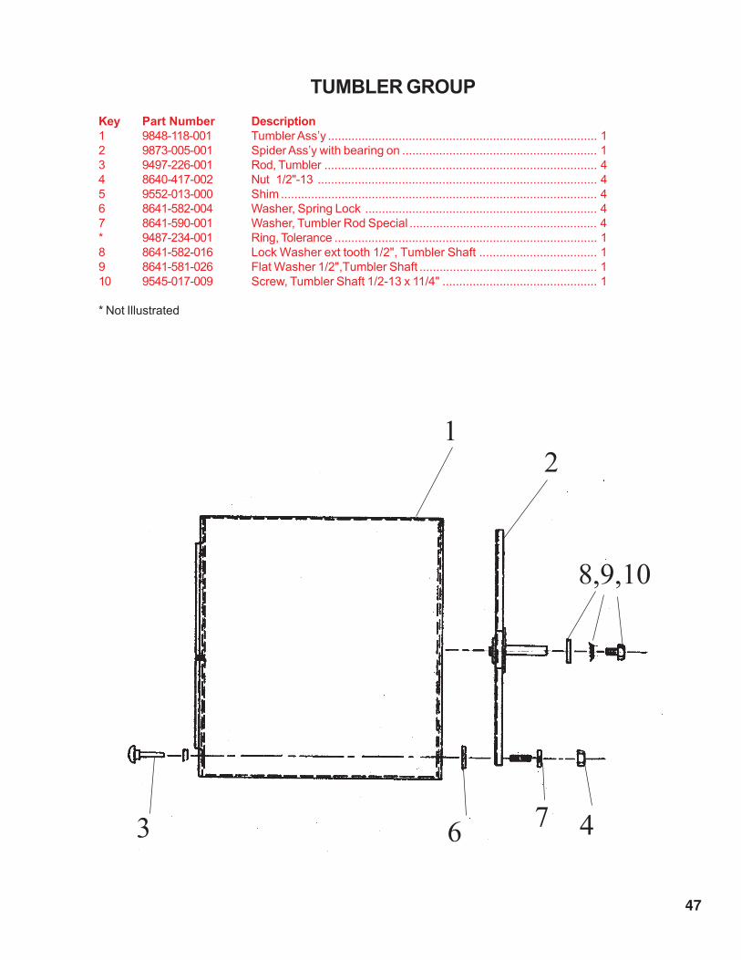
TUMBLER GROUP
Key Part Number Description
1 9848-118-001 Tumbler Ass’y ................................................................................ 1
2 9873-005-001 Spider Ass’y with bearing on .......................................................... 1
3 9497-226-001 Rod, Tumbler ................................................................................. 4
4 8640-417-002 Nut 1/2"-13 ................................................................................... 4
5 9552-013-000 Shim .............................................................................................. 4
6 8641-582-004 Washer, Spring Lock ..................................................................... 4
7 8641-590-001 Washer, Tumbler Rod Special ........................................................ 4
* 9487-234-001 Ring, Tolerance .............................................................................. 1
8 8641-582-016 Lock Washer ext tooth 1/2", Tumbler Shaft ................................... 1
9 8641-581-026 Flat Washer 1/2",Tumbler Shaft ..................................................... 1
10 9545-017-009 Screw, Tumbler Shaft 1/2-13 x 11/4" .............................................. 1
* Not Illustrated
12
8,9,10
3 67 4

48
2
3
6
13
BURNER HOUSING GROUPKey Part Number Description Qty.
1 9803-195-001 Housing Assembly, Burner ............................................................ 1
* 9545-008-024 Screw ............................................................................................ 4
2 9548-280-001 Support, Front Burner .................................................................... 1
3 9545-008-008 Screw 10T-32 x 1/2" ...................................................................... 1
4 9048-018-001 Burner, Main .................................................................................. 4
5 9545-008-008 Screw 10T-32 x 1/2" ...................................................................... 4
6 9875-002-002 Electrode, Ignition .......................................................................... 1
7 9452-645-001 Plate, Electrode Mtg ...................................................................... 1
8 9545-045-001 Screw, Electrode Mtg 8B x 11/4" ................................................... 2
9 9379-164-002 Valve, Gas Shut-Off w/ brass union................................................ 1
10 9458-020-004 Pipe, Gas Line ............................................................................... 1
11 9039-915-001 Bracket, Gas Line Pipe ................................................................. 1
12 9857-134-002 Control Assy, Gas ......................................................................... 1
* 8220-001-466 Wire Assembly Yellow 4 7/8" ......................................................... 1
13 9381-011-001 Manifold Assy., 4 port .................................................................... 1
* 9425-069-021 Orifice, Burner - Natural ................................................................. 4
* 9425-069-022 Orifice, Burner - LP ........................................................................ 4
* 9732-102-010 Kit, LP Conversion ......................................................................... 1
14 9576-203-002 Thermostat, Hi-Limit ...................................................................... 1
15 9538-142-001 Spacer, Hi-Limit ............................................................................. 2
16 9545-045-007 Screw 8B x 3/4" ............................................................................ 2
17 9074-234-001 Cover, Hi-Limit Stat ........................................................................ 1
18 9545-008-024 Screw 10B x 3/8" ........................................................................... 1
19 9631-403-003 Wire Ass’y, High Voltage ............................................................... 1
20 9627-711-001 Harness, Low Voltage Ignition ........................................................ 1
* Not Illustrated
1
5 4

49
6
7
8
14
15 & 16
17
18
19
9
20 10
11
12
20

50
DRIVE GROUP
Key Part Number Description Qty.
1 9376-302-001 Motor, Drive Tumble ...................................................................... 1
* 8640-276-003 Wire Nut connector #73B (for302-001) ........................................... 3
1 9376-302-002 Motor, Drive Blower ...................................................................... 1
* 8640-276-003 Wire Nut connector #73B (for302-002) ........................................... 3
* 9545-014-004 Screw, Hx 5/16-18X5/8 .................................................................. 8
* 8640-400-003 Nut 5/16-18 .................................................................................... 8
* 8641-581-008 Washer Flat 5/16 .......................................................................... 2
2 9453-157-001 Pulley, Motor (for302-001) ............................................................. 1
2 9278-037-003 Impeller, w/set screws (for302-002) ................................................ 1
* 9545-028-013 Screw, Set 5/16-18x1/2" ................................................................ 2
3 9991-054-006 Support Ass’y, Motor (for302-001) .................................................. 1
* 9452-643-002 Plate, Motor (for302-001) ............................................................... 1
4 9545-029-005 Screw 3/8-16 x 1" .......................................................................... 8
5 8640-415-004 Nut 3/8-16 ...................................................................................... 8
6 9991-053-001 Support Assy, Intermed. Pulley (for302-001) .................................. 1
7 9545-029-010 Bolt, Rd Hd 3/8-16x1 1/4 ............................................................... 3
8 9545-029-003 Screw Hxcap 3/8-16x1 1/2 ............................................................ 1
9 8640-415-004 Nut 3/8-16 .................................................................................... 3
* 8641-581-035 Washer, Flat .................................................................................. 4
10 9861-024-002 Arm Assy-Tension Complete.......................................................... 1
* 8641-581-035 Washer, Flat .................................................................................. 1
* 9487-200-006 Ring-Retaining ............................................................................... 1
* 8641-581-039 Washer, Flat............................................................................ 2
11 8640-425-002 Nut-Hex, 5/8 x 11...................................................................... 1
12 9908-042-006 Pulley Assy, Intermediate - w/ bearings, spacer, & ret. ring (below) 1
* 9036-159-007 Bearing, Ball-Idler Pulley ............................................................... 2
* 9538-173-002 Spacer, Bearing ............................................................................. 1
* 9487-238-005 Ring, Retaining ........................................................................ 1
* 9908-042-005 Pulley Assembly intermediate ....................................................... 1
* 8600-042-004 Lubricant molycoat BR2-S .............................................................
13 9487-200-003 Ring, Retaining ........................................................................ 2
14 9908-043-002 Pulley, Assembly Driven ................................................................ 1
* 9487-234-001 Ring, Tolerance .............................................................................. 1
15 8641-581-026 Washer, Flat 1/2 ............................................................................ 1
15 8641-582-016 Lockwasher Ext. 1/2 ...................................................................... 1
15 9545-017-009 Screw, Hx Cap 1/2-13x11/2 ........................................................... 1
16 9040-077-005 Belt, Tumbler Drive ........................................................................ 1
17 9040-077-003 Belt, Drive ...................................................................................... 1
18 9534-151-000 Spring, Belt Tension ....................................................................... 1
19 9099-012-002 Chain, Spring Tension .................................................................... 1
20 9248-022-002 Hook, Tension ................................................................................ 1
21 9074-275-004 Cover-Blower Impeller .................................................................... 1
22 9074-275-005 Cover-Blower Impeller .................................................................... 1
23 9545-008-001 Screw 10B x 1/4" ........................................................................... 4
* 9208-050-001 Guard Rear, Drive........................................................................... 1
* 9454-685-001 Panel, Drive Guard, RH.................................................................. 1
* 9550-180-001 Shield, Motor ................................................................................. 1
* 9545-008-003 Screw 10-16x 1/2 Tek .................................................................... 2
* 9545-008-001 Screw 10Bx1/4 .............................................................................. 11
* Not Illustrated

51
1
2
17
3
11
12
16
3
7&9
15
10 18 8 6
14
19
22 21 23
5/16"bolt 20
4&5

52
AIR FLOW SWITCH, LINT HOOD & BLOWER IMPELLER GROUP
Key Part Number Description Qty.
1 9539-461-009 Switch, Air Flow ............................................................................. 1
* 9550-169-003 Shield, Air Flow Switch.............................................................. 1
2 9545-020-001 Screw, Hx #4-40x5/8 ..................................................................... 2
3 8640-401-001 Nut, Special Twin #4-40 ................................................................. 1
4 9008-007-001 Actuator-Switch, Air Flow .............................................................. 1
5 9451-169-002 Pin, Cotter ..................................................................................... 1
6 9834-009-001 Hood Ass’y, Lint ............................................................................ 1
* 8640-412-004 Nut, Whizlock ................................................................................ 6
* 9822-031-002 Lint Screen 34" length ................................................................... 1
7 9278-037-003 Impeller, w/set screws ................................................................... 1
8 9376-302-002 Motor, Blower .......................................................................... 1
* 9074-275-002 Cover-Half, Blower Impeller (Flat) ................................................... 1
* 9074-275-003 Cover-Half, Blower Impeller (Formed) ............................................. 1
* 9545-008-001 Screw, Hex #10Bx1/4 .................................................................... 4
* 9576-207-006 Thermostat, Safety ........................................................................ 1
9 9825-057-002 Cover, Safety Thermostat........................................................... 1
* 9545-008-024 Screw, Hx. #10ABx3/8 .................................................................. 2
* Not Illustrated 3
1
2
6 9 7 8
4 5

53
WIRING GROUP
1 6068-044-008 Conduit 1/2 x 66" use at top motor 1
* 8653-068-007 Connector 1/2" 45 use at top motor 1
* 8653-068-005 Connector 1/2" Str. use at top motor 1
* 2114-018-001 Bushing Anti-short 1/2 use at top motor 2
* 8220-088-007 Wire red/yel 79" use at top motor 1
* 8220-088-008 Wire wht/yel 79" use at top motor 1
* 8220-088-009 Wire blu/wht 79" use at top motor 1
2 6068-044-006 Conduit 1/2 x 25" use at blower motor 1
* 8653-068-005 Connector 1/2" 45 use at blower motor 2
* 2114--018-001 Bushing Anti-short 1/2 use at blower motor 2
* 8220-057-001 Wire Assy. Gry, 34" use at blower motor 1
* 8220-057-002 Wire Assy. Brn, 34" use at blower motor 1
* 8220-088-004 Wire Assy, Red, 41" use at blower motor 1
* 8220-088-005 Wire Assy. Wht, 41" use at blower motor 1
* 8220-088-006 Wire Assy. Blk, 41" use at blower motor 1
3 6068-037-026 Conduit 3/8 x 44 1/2 use at Hi limit burner 1
* 8653-068-003 Connector 3/8" Str use at Hi limit burner 1
* 8653-068-004 Connector 3/8" 90 use at Hi limit burner 1
* 2114-008-000 Bushing Anti-short 3/8 use at Hi limit burner 2
* 8220-095-023 Wire Assy. Brn, 54" use at Hi limit burner 1
* 8220-103-001 Wire Assy. Vio, 54" use at Hi limit burner 1
4 6068-037-028 Conduit 3/8 x 26 1/2 use at air flow switch 1
* 8653-068-003 Connector 3/8" Str use at air flow switch 1
* 8653-068-004 Connector 3/8" 90 use at air flow switch 1
* 2114-008-000 Bushing Anti-short 3/8 use at air flow switch 1
* 8220-078-007 Wire Assy. Blk 40" use at air flow switch 1
* 8220-064-008 Wire Assy. Brn 40" use at air flow switch 1
5 6068-037-022 Conduit 3/8 x 23 1/2 use at manual reset hi limit 1
* 8653-068-006 Connector 3/8" 45 use at manual reset hi limit 1
* 8653-068-004 Connector 3/8" 90 use at manual reset hi limit 1
* 2114-008-000 Bushing Anti-short 3/8 use at manual reset hi limit 2
* 8220-101-008 Wire Assy. Blk. 34" use at manual reset hi limit 1
* 8220-101-009 Wire Assy. Red 34" use at manual reset hi limit 1
6 6068-044-005 Conduit 1/2 x 90" at rear to front 1
* 8653-068-005 Connector 1/2" Str at rear to front 1
* 8653-068-007 Connector 1/2" 45 at rear to front 1
* 2114-018-001 Bushing Anti-short 1/2 at rear to front 2
* 8220-062-004 Wire Assy. Wht. 108" at rear to front 1
* 8220-065-028 Wire Assy. Vio 110" at rear to front 1
* 8220-062-006 Wire Assy. Blk. 124" at rear to front 1
* 8220-064-005 Wire Assy. Red 108" at rear to front 1
* 8220-064-006 Wire Assy. Gray 110' at rear to front 1
* 8220-065-019 Wire Assy. Wht/Org 110" at rear to front 1
* 8220-065-020 Wire Assy. Org 110" at rear to front 1
* 8220-001-230 Wire Assy. Blk/Red 8 1/2" in control box 1
* 8220-001-231 Wire Assy. Blk/Blu in control box 1
* 8220-001-478 Wire Assy. Grn. 7" in control box 1
* 8220-065-006 Wire Assy. Blk/Red 11" in control box 3
* 8220-065-007 Wire Assy. Blk/Blu 11" in control box 1
* 8220-068-001 Wire Assy. Blk/Red 5" in control box 7
* 8220-068-002 Wire Assy. Blk/Red 7" in control box 1
* 8220-068-004 Wire Assy. Blk/Red 11" in control box 2
* 8220-112-001 Wire Assy. Jumper in control box 1
Key Part number Description Qty.

54
Section 7Maintenance
MAKE SURE ALL POWER IS DISCONNECTEDMAKE SURE ALL POWER IS DISCONNECTEDMAKE SURE ALL POWER IS DISCONNECTEDMAKE SURE ALL POWER IS DISCONNECTEDMAKE SURE ALL POWER IS DISCONNECTED
BEFOREBEFOREBEFOREBEFOREBEFORE MAKING CHECKS INSIDE MACHINE.MAKING CHECKS INSIDE MACHINE.MAKING CHECKS INSIDE MACHINE.MAKING CHECKS INSIDE MACHINE.MAKING CHECKS INSIDE MACHINE.
Daily
1. Clean lint screen by unlocking and sliding out in their tracks for access. Use soft brush if
necessary. Failure to do so will slow drying and increase gas usage and temperatures
throughout the dryer.
2. Check lint screen for tears. Replace if necessary.
Monthly
1. Remove lint accumulation from end bells of motor.
2. Clean lint from lint screen compartment.
3. Remove lint and dirt accumulation from top of the dryer and all area above, and around the
burners and burner housing.
Failure to keep this portion of the dryer clean can lead to a build-up of lint creating
a fire hazard.
4. Place a few drops of light oil on top and bottom pivots of the clothes door hinge.
5. Grease bearings and shaft of intermediate drive pulley.
Quarterly
1. Check belts for looseness, wear or fraying.
2. Inspect gasket of door glass for excessive wear.
3. Check tightness of all fasteners holding parts to support channel.
4. Check tightness of tumbler shaft retaining nut.
5. Remove lint accumulation from primary air ports in burners.
6. Grease pivot pins and tension arms where in contact with each other.
Semi-Annually
1. Remove and clean main burners.
2. Remove all orifices and examine for dirt and hole obstruction.
3. Remove all lint accumulation. Remove front panel, lint screen housing and remove lint
accumulation.
Annually
1. Check intermediate pulley bearings for wear.
2. Remove, inspect and clean main burner orifices of obstruc-

55
Timer Model
Micro Model
Micro Model w/ Reversing Cylinder
Capacity
Dry Weight Capacity 30 lbs 13.5 kg 55 lbs 24.8 kg 80 lbs 36.3 kg 80 lbs 36.3 kg
Cylinder Diameter 30" 76.2 cm 32.5" 82.55 cm 36.5" 92.71 cm 36.5" 92.71 cm
Cylinder Depth 29.5" 74.93 cm 38" 96.52 cm 38" 96.52 cm 38" 96.52 cm
Cylinder Volume 12.1 cu ft 341.78 dm³ 18.2 cu ft 516.5 dm³ 23 cu ft 651.29 dm³ 23 cu ft 651.29 dm³
Dimensions
Cabinet Height (with feet)- Minimum 72.625" 184.47 cm 72.25" 183.52 cm 75.5" 191.77 cm 75.5" 191.77 cm
Cabinet Height (with feet)- Maximum 73.625" 187.01 cm 73.25" 186.06 cm 76.5" 194.31 cm 76.5" 194.31 cm
Cabinet Width 31.5" 80.01 cm 34.4375" 87.47 cm 38.4375" 97.53 cm 38.4375" 97.53 cm
Overall Depth 43.375" 110.17 cm 51.125" 129.86 cm 51.125" 129.86 cm 51.125" 129.86 cm
Floor to Door Bottom 30.5625" 77.63 cm 29.5" 74.93 cm 31" 78.74 cm 31" 78.74 cm
Door Opening 22.6875" 57.63 cm 22.6875" 57.63 cm 22.6875" 57.63 cm 22.6875" 57.63 cm
Electrical
Electrical Phase
Electrical Voltage (60 Hz)
Electrical Running Amps (60 Hz)
Circuit Protection (60 Hz)
Electrical Voltage (50 Hz)
Electrical Running AMPs (50 Hz)
Circuit Protection (50 Hz)
Electrical Wire Size
Electrical Service (Single Phase)
Motor Size 1/2 HP .37 kW 3/4 HP .56 kW 1 HP .75 kW (2) 1 HP (2) .75 kW
Tumble Direction
Tumble Speed
Gas Heat
Gas Input/Hour 90,000 BTU 22,680 kcal 160,000 BTU 40,320 kcal 215,000 BTU 54,180 kcal 215,000 BTU 54,180 kcal
Gas Supply Connection (NPT) 1/2" 12.7 mm 1/2" 12.7 mm 1/2" 12.7 mm 1/2" 12.7 mm
Natural Gas Supply (Water Column) 5 -10" 12.7 - 25.4 cm 5 -10" 12.7 - 25.4 cm 5 -10" 12.7 - 25.4 cm 5 -10" 12.7 - 25.4 cm
L.P. Supply (Water Column) 11 -13.5" 27.9 - 34.29 cm 11 -13.5" 27.9 - 34.29 cm 11 -13.5" 27.9 - 34.29 cm 11 -13.5" 27.9 - 34.29 cm
Electric Heat (Voltage/Hz/Phase) Model AMP/Circuit Model AMP/Circuit Model AMP/Circuit
208 / 60 / 1 - 20 kW -60FA 113/125
240 / 60 / 1 - 20 kW -61FB 99/110
208 / 60 / 3 - 24 kW -16FC 82/90 -16FC 80/80
240 / 60 / 3 - 24 kW -18FD 72/80 -18FD 71/90
208 / 60 / 3 - 30 kW -16FE 99/100 -16FE 97/100 -16FE 95/100
240 / 60 / 3 - 30 kW -18FG 88/90 -18FG 86/90 -18FG 83/90
208 / 60 / 3 - 35 kW -16FH 112/125
240 / 60 / 3 - 36 kW -18FJ 98/110
Steam Heat
At PSIG (bar) 97 (6.69) 3.25 BHP 97 (6.69) 5 BHP 97 (6.69) 6.3 BHP
BTU/Hour (kW) 109,000 32 167,000 49 212,000 62
Steam Supply Connection (NPT) 1" 25.4 mm 1" 25.4 mm 1" 25.4 mm
Steam Return Connection (NPT) 3/4" 19 mm 3/4" 19 mm 3/4" 19 mm
Installation
Air Flow 830 CFM 23.51 M³/min 910 CFM 25.77 M³/min 1,200 CFM 33.98 M³/min 1,200 CFM 33.98 M³/min
Exhaust Size (Vent Diameter) 8" 20.32 cm 8" 20.32 cm 8" 20.32 cm 8" 20.32 cm
Make-Up Air (Minimum) 1 ft² 929 cm² 1 ft² 929 cm² 1.5 ft² 1394 cm² 1.5 ft² 1394 cm²
Net Weight 452 lbs 204 kg 581 lbs 262 kg 613 lbs 276 kg 613 lbs 276 kg
Net Weight w/ Reversing Option 743 lbs 335 kg 743 lbs 335 kg
Clearance Behind Machines (Minimum) 18" 45.72 cm 18" 45.72 cm 18" 45.72 cm 18" 45.72 cm
2/4/5 Year Dryer Warranty
Dexter warrants all dryers parts that fail under normal use for 2 years from date of installation.
All dryer computers and ignition controls are warranted for 4 years from date of installation.
The dryer bearings, bearing housing, and trunion are warranted for 5 years from date of installation.
The Dexter Company
2211 West Grimes Avenue
Fairfield, Iowa, USA 52556 Specifications subject to change Rev. 5/04
Fax: 800-349-2417
www.dexterlaundry.com
SpecificationsIndustrial Dryers
Three
5
208-240 V
5
15 AMP
DLH30
47 RPM 45 RPM 40 RPM
Counter Clockwise
40 RPM
Reversing
3 wire + ground
12 gauge
Counter Clockwise
7.5
220-240 V
10 AMP
220-240 V
10 AMP
DRH55 DRH80
DTCH30 DTCH55 DTCH80
9.6 7.8
DTCH80V
Single
120/208-240 V
10.8
Single
120 V
5.1
12 gauge 12 gauge
15 AMP 15 AMP
Single
120 V
220-240 V
Counter Clockwise
2 wire + ground 2 wire + ground
10 AMP
2 wire + ground
12 gauge
15 AMP