8' x 7' Vinyl Storage Shed - Vision...
16
8' x 7' Vinyl Storage Shed Owner’s Manual 8' x 7' (2.44m x 2.14m) PLEASE READ OWNER’S MANUAL COMPLETELY BEFORE ASSEMBLING YOUR BUILDING. ALL STATED SIZES ARE NOMINAL DIMENSIONS. Model #S-8070-A Storage Shed Model #S-8070-B Storage Shed with Base Included
Transcript of 8' x 7' Vinyl Storage Shed - Vision...
8' x 7' Vinyl Storage Shed
Owner’s Manual8' x 7' (2.44m x 2.14m)
PLEASE READ OWNER’S MANUAL COMPLETELY BEFORE ASSEMBLING YOUR BUILDING.
ALL STATED SIZES ARE NOMINAL DIMENSIONS.
Model #S-8070-A Storage ShedModel #S-8070-B Storage Shed with Base Included
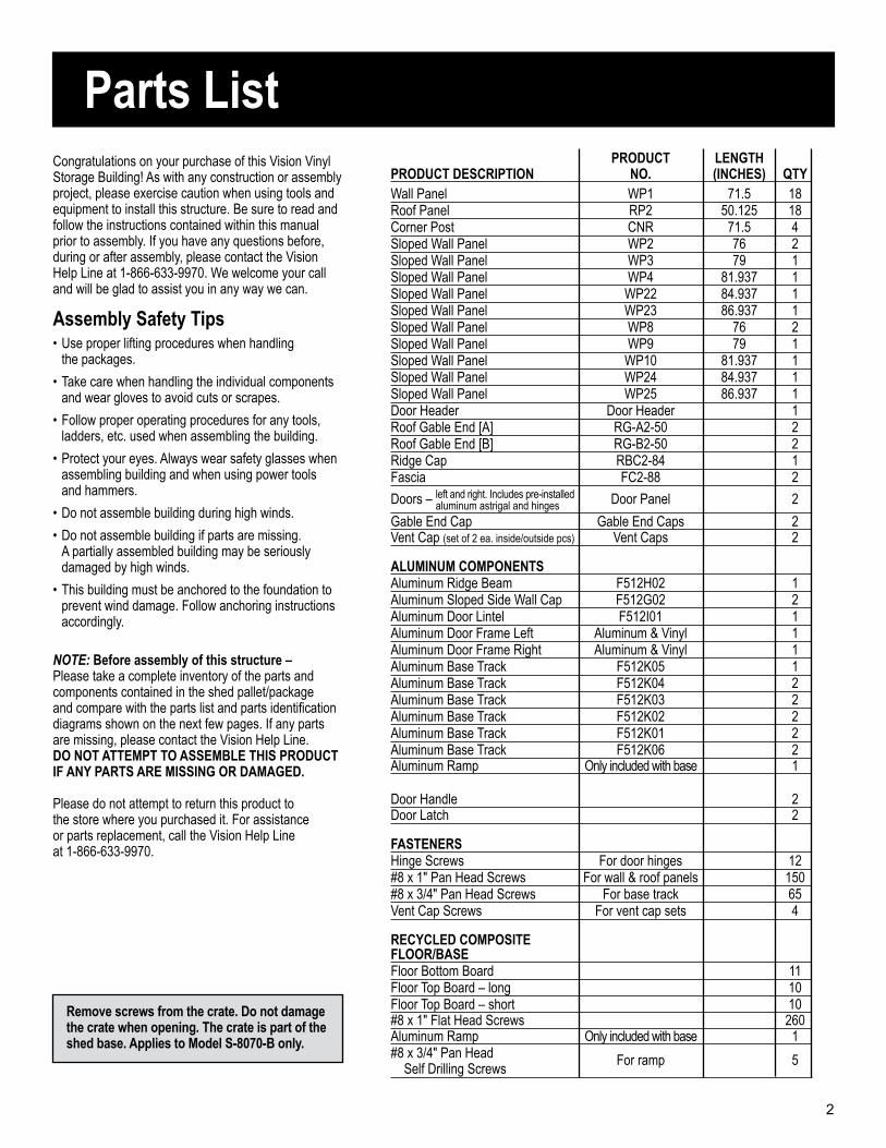
Parts ListCongratulations on your purchase of this Vision Vinyl Storage Building! As with any construction or assembly project, please exercise caution when using tools and equipment to install this structure. Be sure to read and follow the instructions contained within this manual prior to assembly. If you have any questions before, during or after assembly, please contact the Vision Help Line at 1-866-633-9970. We welcome your call and will be glad to assist you in any way we can.
Assembly Safety Tips• Use proper lifting procedures when handling the packages.
• Take care when handling the individual components and wear gloves to avoid cuts or scrapes.
• Follow proper operating procedures for any tools, ladders, etc. used when assembling the building.
• Protect your eyes. Always wear safety glasses when assembling building and when using power tools and hammers.
• Do not assemble building during high winds.
• Do not assemble building if parts are missing. A partially assembled building may be seriously damaged by high winds.
• This building must be anchored to the foundation to prevent wind damage. Follow anchoring instructions accordingly.
NOTE: Before assembly of this structure – Please take a complete inventory of the parts and components contained in the shed pallet/package and compare with the parts list and parts identification diagrams shown on the next few pages. If any parts are missing, please contact the Vision Help Line. DO NOT ATTEMPT TO ASSEMBLE THIS PRODUCT IF ANY PARTS ARE MISSING OR DAMAGED.
Please do not attempt to return this product to the store where you purchased it. For assistance or parts replacement, call the Vision Help Line at 1-866-633-9970.
PRODUCT LENGTHPRODUCT DESCRIPTION NO. (INCHES) QTY Wall Panel WP1 71.5 18 Roof Panel RP2 50.125 18 Corner Post CNR 71.5 4 Sloped Wall Panel WP2 76 2 Sloped Wall Panel WP3 79 1 Sloped Wall Panel WP4 81.937 1 Sloped Wall Panel WP22 84.937 1 Sloped Wall Panel WP23 86.937 1 Sloped Wall Panel WP8 76 2 Sloped Wall Panel WP9 79 1 Sloped Wall Panel WP10 81.937 1 Sloped Wall Panel WP24 84.937 1 Sloped Wall Panel WP25 86.937 1 Door Header Door Header 1 Roof Gable End [A] RG-A2-50 2 Roof Gable End [B] RG-B2-50 2 Ridge Cap RBC2-84 1 Fascia FC2-88 2
Doors – left and right. Includes pre-installed Door Panel 2 aluminum astrigal and hinges
Gable End Cap Gable End Caps 2 Vent Cap (set of 2 ea. inside/outside pcs) Vent Caps 2
ALUMINUM COMPONENTS Aluminum Ridge Beam F512H02 1 Aluminum Sloped Side Wall Cap F512G02 2 Aluminum Door Lintel F512I01 1 Aluminum Door Frame Left Aluminum & Vinyl 1 Aluminum Door Frame Right Aluminum & Vinyl 1 Aluminum Base Track F512K05 1 Aluminum Base Track F512K04 2 Aluminum Base Track F512K03 2 Aluminum Base Track F512K02 2 Aluminum Base Track F512K01 2 Aluminum Base Track F512K06 2 Aluminum Ramp Only included with base 1
Door Handle 2 Door Latch 2
FASTENERS Hinge Screws For door hinges 12 #8 x 1" Pan Head Screws For wall & roof panels 150 #8 x 3/4" Pan Head Screws For base track 65 Vent Cap Screws For vent cap sets 4
RECYCLED COMPOSITE FLOOR/BASE Floor Bottom Board 11 Floor Top Board – long 10 Floor Top Board – short 10 #8 x 1" Flat Head Screws 260 Aluminum Ramp Only included with base 1 #8 x 3/4" Pan Head For ramp 5 Self Drilling Screws
Remove screws from the crate. Do not damage the crate when opening. The crate is part of the shed base. Applies to Model S-8070-B only.
2
WP2
WP3AluminumDoor Frame Left
WP8WP9
AluminumDoor Frame Right
CNR
F512K04
F512K06
F512K03
F512K03
F512I01
F512K04
F512K06
F512K05
F512K02
F512K02
F512K01
F512K01
CNR
RP2
Outside Vents
Inside Vents
F512H02
Ridge Cap
Gable End Cap
RP2
FC2
FC2
CNR
CNR
WP8
WP1
WP9
WP10
WP24
WP25
WP23 WP22 WP4 WP3 WP2WP1
Door Header
RGA-2
RGA-2
RGB-2
RGB-2
Gable End Cap
F512G02
F512G02
Door
Door
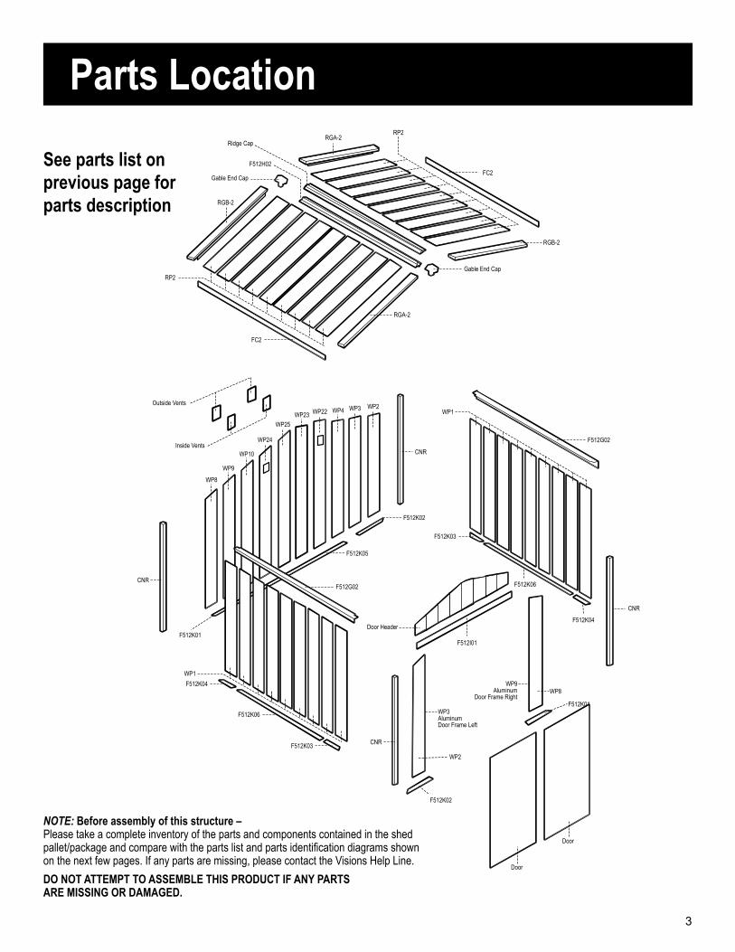
NOTE: Before assembly of this structure – Please take a complete inventory of the parts and components contained in the shed pallet/package and compare with the parts list and parts identification diagrams shown on the next few pages. If any parts are missing, please contact the Visions Help Line.
DO NOT ATTEMPT TO ASSEMBLE THIS PRODUCT IF ANY PARTS ARE MISSING OR DAMAGED.
Parts Location
See parts list on previous page for parts description
3
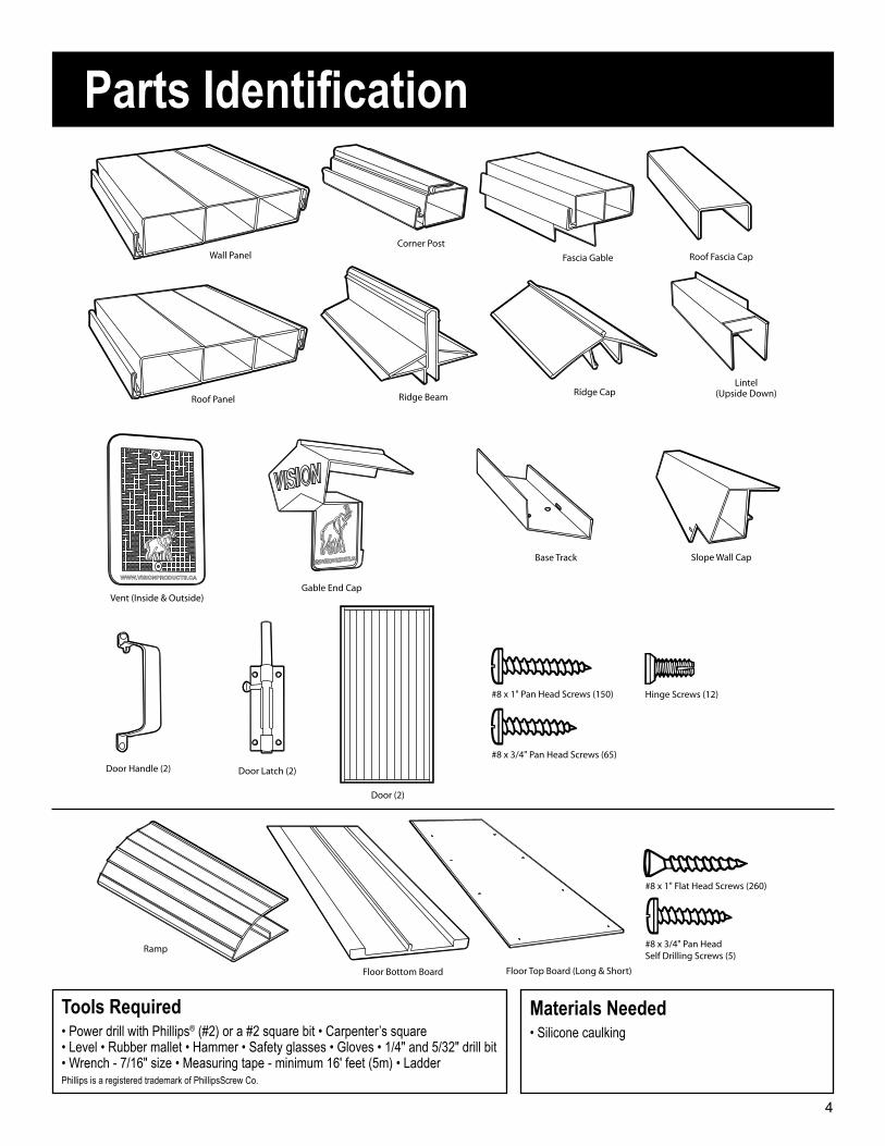
Wall PanelCorner Post
Fascia Gable
Vent (Inside & Outside)
Ridge CapRidge Beam
Gable End Cap
Roof Fascia Cap
Lintel(Upside Down)
Roof Panel
Base Track Slope Wall Cap
Door Handle (2) Door Latch (2)
Door (2)
Floor Bottom Board Floor Top Board (Long & Short)
Ramp
#8 x 1" Pan Head Screws (150) Hinge Screws (12)
#8 x 3/4" Pan Head Screws (65)
#8 x 3/4" Pan Head Self Drilling Screws (5)
#8 x 1" Flat Head Screws (260)
Parts Identification
Tools Required• Power drill with Phillips® (#2) or a #2 square bit • Carpenter’s square• Level • Rubber mallet • Hammer • Safety glasses • Gloves • 1/4" and 5/32" drill bit• Wrench - 7/16" size • Measuring tape - minimum 16' feet (5m) • LadderPhillips is a registered trademark of PhillipsScrew Co.
Materials Needed• Silicone caulking
4
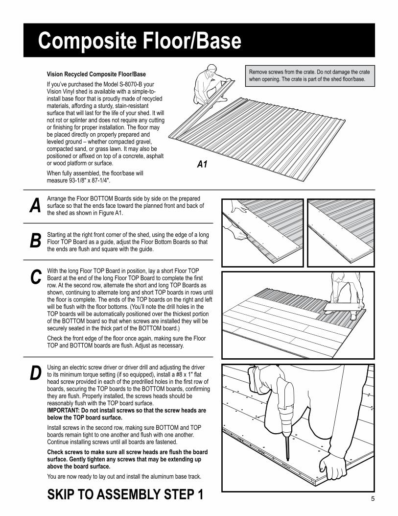
Vision Recycled Composite Floor/Base
If you’ve purchased the Model S-8070-B your Vision Vinyl shed is available with a simple-to-install base floor that is proudly made of recycled materials, affording a sturdy, stain-resistant surface that will last for the life of your shed. It will not rot or splinter and does not require any cutting or finishing for proper installation. The floor may be placed directly on properly prepared and leveled ground – whether compacted gravel, compacted sand, or grass lawn. It may also be positioned or affixed on top of a concrete, asphalt or wood platform or surface.
When fully assembled, the floor/base will measure 93-1/8" x 87-1/4".
Composite Floor/Base
A
B
C
D
Arrange the Floor BOTTOM Boards side by side on the prepared surface so that the ends face toward the planned front and back of the shed as shown in Figure A1.
Starting at the right front corner of the shed, using the edge of a long Floor TOP Board as a guide, adjust the Floor Bottom Boards so that the ends are flush and square with the guide.
With the long Floor TOP Board in position, lay a short Floor TOP Board at the end of the long Floor TOP Board to complete the first row. At the second row, alternate the short and long TOP Boards as shown, continuing to alternate long and short TOP boards in rows until the floor is complete. The ends of the TOP boards on the right and left will be flush with the floor bottoms. (You’ll note the drill holes in the TOP boards will be automatically positioned over the thickest portion of the BOTTOM board so that when screws are installed they will be securely seated in the thick part of the BOTTOM board.)
Check the front edge of the floor once again, making sure the Floor TOP and BOTTOM boards are flush. Adjust as necessary.
Using an electric screw driver or driver drill and adjusting the driver to its minimum torque setting (if so equipped), install a #8 x 1" flat head screw provided in each of the predrilled holes in the first row of boards, securing the TOP boards to the BOTTOM boards, confirming they are flush. Properly installed, the screws heads should be reasonably flush with the TOP board surface. IMPORTANT: Do not install screws so that the screw heads are below the TOP board surface.
Install screws in the second row, making sure BOTTOM and TOP boards remain tight to one another and flush with one another. Continue installing screws until all boards are fastened.
Check screws to make sure all screw heads are flush the board surface. Gently tighten any screws that may be extending up above the board surface.
You are now ready to lay out and install the aluminum base track.
A1
Remove screws from the crate. Do not damage the crate when opening. The crate is part of the shed floor/base.
5SKIP TO ASSEMBLY STEP 1
Concrete Floor OptionConcrete Floor Option
You may decide to construct your Vision storage shed on a concrete foundation, in which case it is recommended that you engage the services of a concrete contractor.
Prior to having a concrete foundation poured please perform the following:
• Make sure your structure will comply with local building codes and ordinances.
• Select a location that is free from ground water and provides suitable drainage, that can be leveled properly and affords ample room to erect the shed.
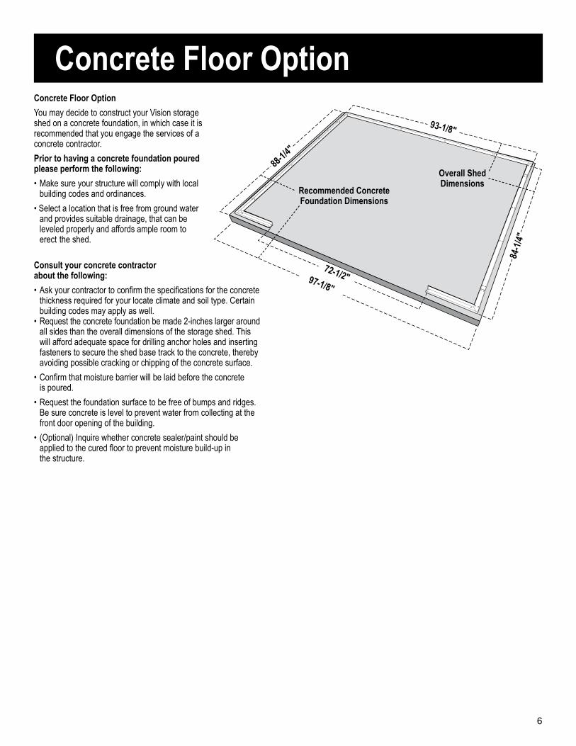
97-1/8"
88-1/
4"
Consult your concrete contractor about the following:
• Ask your contractor to confirm the specifications for the concrete thickness required for your locate climate and soil type. Certain building codes may apply as well.• Request the concrete foundation be made 2-inches larger around all sides than the overall dimensions of the storage shed. This will afford adequate space for drilling anchor holes and inserting fasteners to secure the shed base track to the concrete, thereby avoiding possible cracking or chipping of the concrete surface.
• Confirm that moisture barrier will be laid before the concrete is poured.
• Request the foundation surface to be free of bumps and ridges. Be sure concrete is level to prevent water from collecting at the front door opening of the building.
• (Optional) Inquire whether concrete sealer/paint should be applied to the cured floor to prevent moisture build-up in the structure.
6
72-1/2"
93-1/8"
84-1
/4"
Overall Shed Dimensions
Recommended Concrete Foundation Dimensions
Wood Floor Option
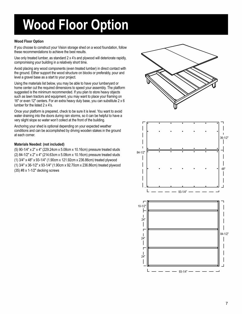
Materials Needed: (not included)(5) 90-1/4" x 2" x 4" (229.24cm x 5.08cm x 10.16cm) pressure treated studs(2) 84-1/2" x 2" x 4" (214.63cm x 5.08cm x 10.16cm) pressure treated studs(1) 3/4" x 48" x 93-1/4" (1.90cm x 121.92cm x 236.86cm) treated plywood(1) 3/4" x 36-1/2" x 93-1/4" (1.90cm x 92.70cm x 236.86cm) treated plywood(35) #8 x 1-1/2" decking screws
93-1/4"
84-1/2"
24"
24"
24"
10-1/2"
93-1/4"
84-1/2"
48"
36-1/2"
Wood Floor Option
If you choose to construct your Vision storage shed on a wood foundation, follow these recommendations to achieve the best results.
Use only treated lumber, as standard 2 x 4’s and plywood will deteriorate rapidly, compromising your building in a relatively short time.
Avoid placing any wood components (even treated lumber) in direct contact with the ground. Either support the wood structure on blocks or preferably, pour and level a gravel base as a start to your project.
Using the materials list below, you may be able to have your lumberyard or home center cut the required dimensions to speed your assembly. The platform suggested is the minimum recommended. If you plan to store heavy objects such as lawn tractors and equipment, you may want to place your framing on 16" or even 12" centers. For an extra heavy duty base, you can substitute 2 x 6 lumber for the listed 2 x 4’s.
Once your platform is prepared, check to be sure it is level. You want to avoid water draining into the doors during rain storms, so it can be helpful to have a very slight slope so water won’t collect at the front of the building.
Anchoring your shed is optional depending on your expected weather conditions and can be accomplished by driving wooden stakes in the ground at each corner.
7
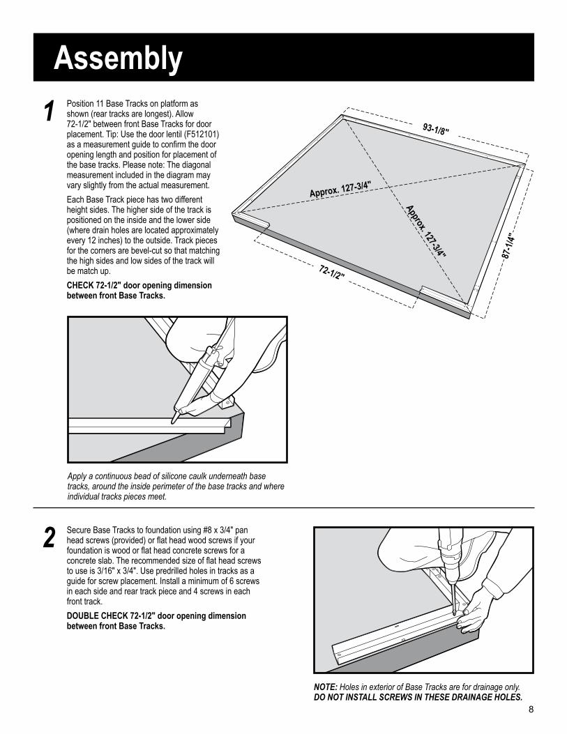
Position 11 Base Tracks on platform as shown (rear tracks are longest). Allow 72-1/2" between front Base Tracks for door placement. Tip: Use the door lentil (F512101) as a measurement guide to confirm the door opening length and position for placement of the base tracks. Please note: The diagonal measurement included in the diagram may vary slightly from the actual measurement.
Each Base Track piece has two different height sides. The higher side of the track is positioned on the inside and the lower side (where drain holes are located approximately every 12 inches) to the outside. Track pieces for the corners are bevel-cut so that matching the high sides and low sides of the track will be match up.
CHECK 72-1/2" door opening dimension between front Base Tracks.
NOTE: Holes in exterior of Base Tracks are for drainage only.DO NOT INSTALL SCREWS IN THESE DRAINAGE HOLES.
Apply a continuous bead of silicone caulk underneath base tracks, around the inside perimeter of the base tracks and where individual tracks pieces meet.
Secure Base Tracks to foundation using #8 x 3/4" pan head screws (provided) or flat head wood screws if your foundation is wood or flat head concrete screws for a concrete slab. The recommended size of flat head screws to use is 3/16" x 3/4". Use predrilled holes in tracks as a guide for screw placement. Install a minimum of 6 screws in each side and rear track piece and 4 screws in each front track.
DOUBLE CHECK 72-1/2" door opening dimension between front Base Tracks.
1
2
72-1/2"
93-1/8"
87-1
/4"
Approx. 127-3/4"
Approx. 127-3/4"
Assembly
8
3
4
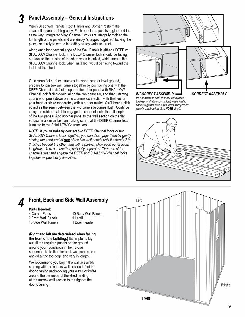
Panel Assembly – General InstructionsVision Shed Wall Panels, Roof Panels and Corner Posts make assembling your building easy. Each panel and post is engineered the same way: Integrated Vinyl Channel Locks are integrally molded the full length of the panels and are simply “snapped together,” locking the pieces securely to create incredibly sturdy walls and roof.
Along each long vertical edge of the Wall Panels is either a DEEP or SHALLOW Channel lock. The DEEP Channel lock should be facing out toward the outside of the shed when installed, which means the SHALLOW Channel lock, when installed, would be facing toward the inside of the shed.
On a clean flat surface, such as the shed base or level ground, prepare to join two wall panels together by positioning one with the DEEP Channel lock facing up and the other panel with SHALLOW Channel lock facing down. Align the two channels, and then, starting at one end, press down on the channel connection with the heel or your hand or strike moderately with a rubber mallet. You’ll hear a click sound as the seam between the two panels becomes flush. Continue using the rubber mallet to engage the channel locks the full length of the two panels. Add another panel to the wall section on the flat surface in a similar fashion making sure that the DEEP Channel lock is mated to the SHALLOW Channel lock.
NOTE: If you mistakenly connect two DEEP Channel locks or two SHALLOW Channel locks together, you can disengage them by gently striking the short end of one of the two wall panels until it extends 2 to 3 inches beyond the other, and with a partner, slide each panel away, lengthwise from one another, until fully separated. Turn one of the channels over and engage the DEEP and SHALLOW channel locks together as previously described.
Front, Back and Side Wall Assembly
Parts Needed:4 Corner Posts 10 Back Wall Panels2 Front Wall Panels 1 Lentil18 Side Wall Panels 1 Door Header
(Right and left are determined when facing the front of the building.) It’s helpful to lay out all the required panels on the ground around your foundation in their proper sequence. Note that the back wall panels are angled at the top edge and vary in length.
We recommend you begin the wall assembly starting with the narrow wall section left of the door opening and working your way clockwise around the perimeter of the shed, ending at the narrow wall section to the right of the door opening.
Left
Right
Front
INCORRECT ASSEMBLYDo not connect “like” channel locks (deep-to-deep or shallow-to-shallow) when joining panels together as this will result in improper/unsafe construction. See NOTE at left.
9
CORRECT ASSEMBLY
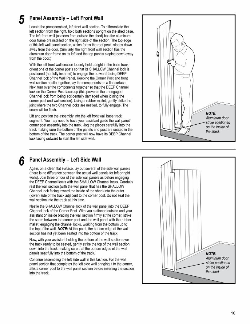
Panel Assembly – Left Front WallLocate the preassembled, left front wall section. To differentiate the left section from the right, hold both sections upright on the shed base. The left front wall (as seen from outside the shed) has the aluminum door frame preinstalled on the right side of the section. The top edge of this left wall panel section, which forms the roof peak, slopes down away from the door. (Similarly, the right front wall section has the aluminum door frame on its left and the top panels sloping down away from the door.)
With the left front wall section loosely held upright in the base track, orient one of the corner posts so that its SHALLOW Channel lock is positioned (not fully inserted) to engage the outward facing DEEP Channel lock of the Wall Panel. Keeping the Corner Post and front wall section nestle together, lay the components on a flat surface. Next turn over the components together so that the DEEP Channel lock on the Corner Post faces up (this prevents the unengaged Channel lock from being accidentally damaged when joining the corner post and wall section). Using a rubber mallet, gently strike the joint where the two Channel locks are nestled, to fully engage. The seam will be flush.
Lift and position the assembly into the left front wall base track segment. You may need to have your assistant guide the wall panel/corner post assembly into the track. Jog the pieces carefully into the track making sure the bottom of the panels and post are seated in the bottom of the track. The corner post will now have its DEEP Channel lock facing outward to start the left side wall.
5
Panel Assembly – Left Side WallAgain, on a clean flat surface, lay out several of the side wall panels (there is no difference between the actual wall panels for left or right walls). Join three or four of the side wall panels as before engaging the DEEP Channel locks with the SHALLOW Channel locks. Carefully rest the wall section (with the wall panel that has the SHALLOW Channel lock facing toward the inside of the shed) into the outer (lower) side of the track adjacent to the corner post. Do not seat the wall section into the track at this time.
Nestle the SHALLOW Channel lock of the wall panel into the DEEP Channel lock of the Corner Post. With you stationed outside and your assistant on inside bracing the wall section firmly at the corner, strike the seam between the corner post and the wall panel with the rubber mallet, engaging the channel locks, working from the bottom up to the top of the wall. NOTE: At this point, the bottom edge of the wall section has not yet been seated into the bottom of the track.
Now, with your assistant holding the bottom of the wall section over the track ready to be seated, gently strike the top of the wall section down into the track, making sure that the bottom edges of the wall panels seat fully into the bottom of the track.
Continue assembling the left side wall in this fashion. For the wall panel section that completes the left side wall bringing it to the corner, affix a corner post to the wall panel section before inserting the section into the track.
6
NOTE: Aluminum door strike positioned on the inside of the shed.
NOTE: Aluminum door strike positioned on the inside of the shed.
10
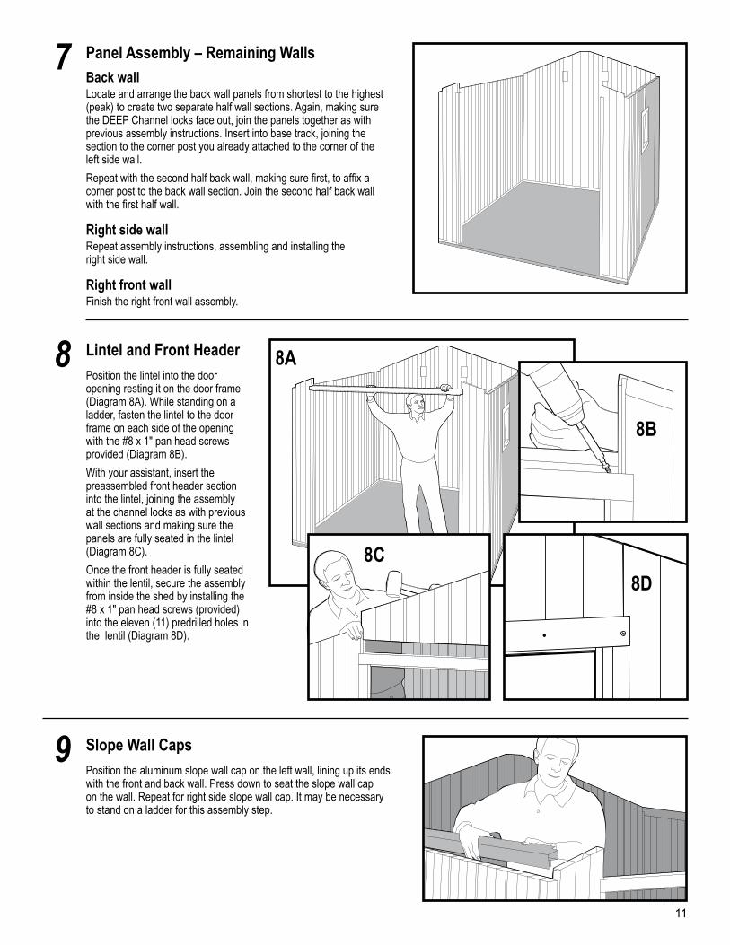
Panel Assembly – Remaining WallsBack wallLocate and arrange the back wall panels from shortest to the highest (peak) to create two separate half wall sections. Again, making sure the DEEP Channel locks face out, join the panels together as with previous assembly instructions. Insert into base track, joining the section to the corner post you already attached to the corner of the left side wall.
Repeat with the second half back wall, making sure first, to affix a corner post to the back wall section. Join the second half back wall with the first half wall.
Right side wallRepeat assembly instructions, assembling and installing the right side wall.
Right front wallFinish the right front wall assembly.
7
Lintel and Front HeaderPosition the lintel into the door opening resting it on the door frame (Diagram 8A). While standing on a ladder, fasten the lintel to the door frame on each side of the opening with the #8 x 1" pan head screws provided (Diagram 8B).
With your assistant, insert the preassembled front header section into the lintel, joining the assembly at the channel locks as with previous wall sections and making sure the panels are fully seated in the lintel (Diagram 8C).
Once the front header is fully seated within the lentil, secure the assembly from inside the shed by installing the #8 x 1" pan head screws (provided) into the eleven (11) predrilled holes in the lentil (Diagram 8D).
8
Slope Wall CapsPosition the aluminum slope wall cap on the left wall, lining up its ends with the front and back wall. Press down to seat the slope wall cap on the wall. Repeat for right side slope wall cap. It may be necessary to stand on a ladder for this assembly step.
9
8A
8B
8C
11
8D
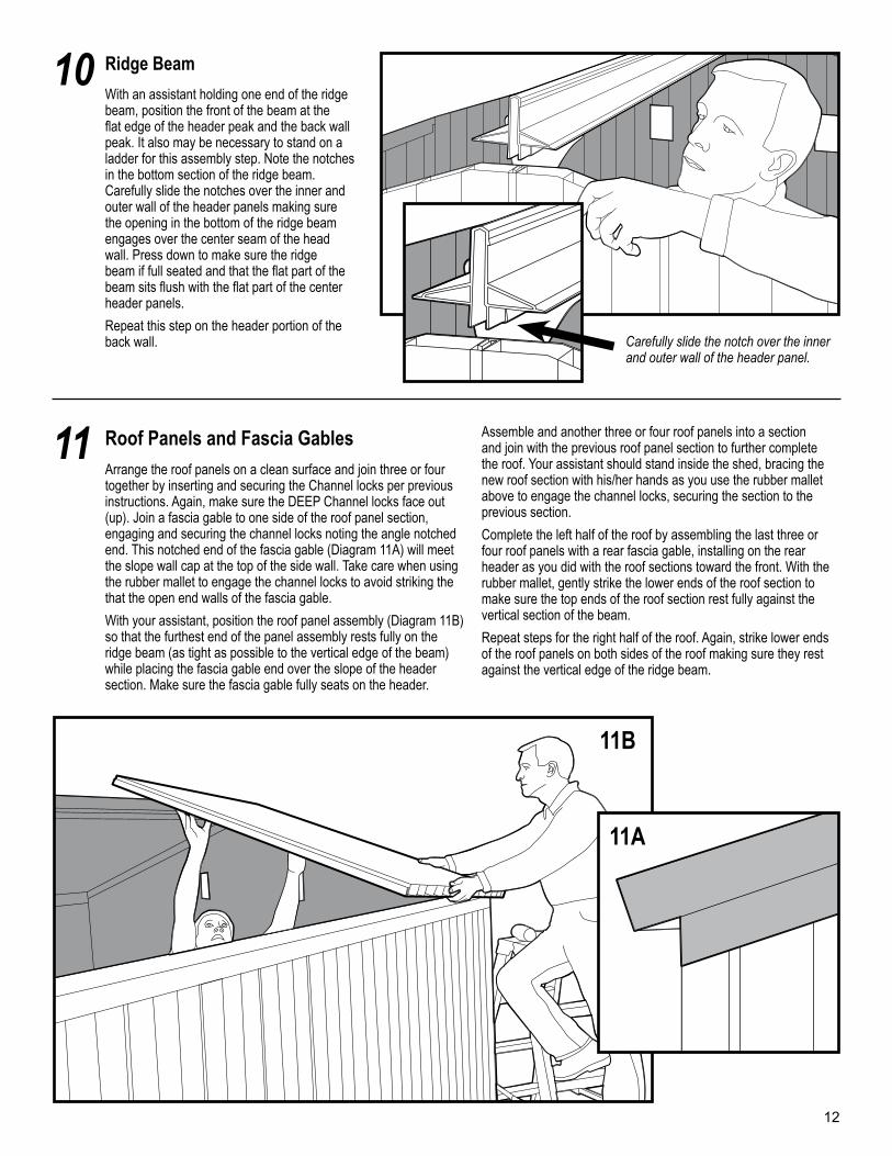
Ridge Beam
With an assistant holding one end of the ridge beam, position the front of the beam at the flat edge of the header peak and the back wall peak. It also may be necessary to stand on a ladder for this assembly step. Note the notches in the bottom section of the ridge beam. Carefully slide the notches over the inner and outer wall of the header panels making sure the opening in the bottom of the ridge beam engages over the center seam of the head wall. Press down to make sure the ridge beam if full seated and that the flat part of the beam sits flush with the flat part of the center header panels.
Repeat this step on the header portion of the back wall.
10
Roof Panels and Fascia GablesArrange the roof panels on a clean surface and join three or four together by inserting and securing the Channel locks per previous instructions. Again, make sure the DEEP Channel locks face out (up). Join a fascia gable to one side of the roof panel section, engaging and securing the channel locks noting the angle notched end. This notched end of the fascia gable (Diagram 11A) will meet the slope wall cap at the top of the side wall. Take care when using the rubber mallet to engage the channel locks to avoid striking the that the open end walls of the fascia gable.
With your assistant, position the roof panel assembly (Diagram 11B) so that the furthest end of the panel assembly rests fully on the ridge beam (as tight as possible to the vertical edge of the beam) while placing the fascia gable end over the slope of the header section. Make sure the fascia gable fully seats on the header.
Assemble and another three or four roof panels into a section and join with the previous roof panel section to further complete the roof. Your assistant should stand inside the shed, bracing the new roof section with his/her hands as you use the rubber mallet above to engage the channel locks, securing the section to the previous section.
Complete the left half of the roof by assembling the last three or four roof panels with a rear fascia gable, installing on the rear header as you did with the roof sections toward the front. With the rubber mallet, gently strike the lower ends of the roof section to make sure the top ends of the roof section rest fully against the vertical section of the beam.
Repeat steps for the right half of the roof. Again, strike lower ends of the roof panels on both sides of the roof making sure they rest against the vertical edge of the ridge beam.
11
Carefully slide the notch over the inner and outer wall of the header panel.
11B
11A
12
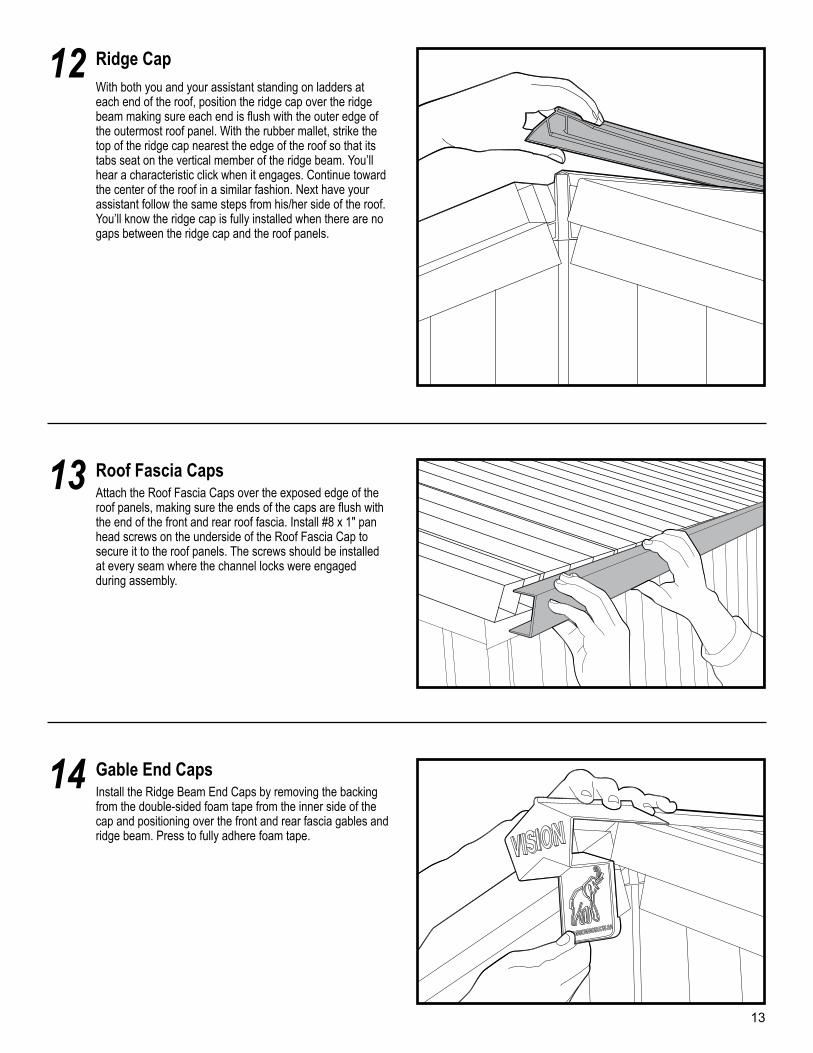
Ridge CapWith both you and your assistant standing on ladders at each end of the roof, position the ridge cap over the ridge beam making sure each end is flush with the outer edge of the outermost roof panel. With the rubber mallet, strike the top of the ridge cap nearest the edge of the roof so that its tabs seat on the vertical member of the ridge beam. You’ll hear a characteristic click when it engages. Continue toward the center of the roof in a similar fashion. Next have your assistant follow the same steps from his/her side of the roof. You’ll know the ridge cap is fully installed when there are no gaps between the ridge cap and the roof panels.
12
Roof Fascia CapsAttach the Roof Fascia Caps over the exposed edge of the roof panels, making sure the ends of the caps are flush with the end of the front and rear roof fascia. Install #8 x 1" pan head screws on the underside of the Roof Fascia Cap to secure it to the roof panels. The screws should be installed at every seam where the channel locks were engaged during assembly.
13
Gable End CapsInstall the Ridge Beam End Caps by removing the backing from the double-sided foam tape from the inner side of the cap and positioning over the front and rear fascia gables and ridge beam. Press to fully adhere foam tape.
14
13
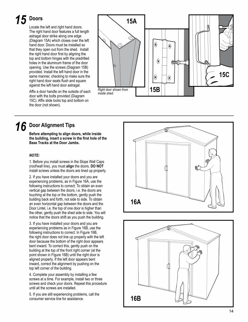
DoorsLocate the left and right hand doors. The right hand door features a full length astragal door strike along one edge (Diagram 15A) which closes over the left hand door. Doors must be installed so that they open out from the shed. Install the right hand door first by aligning the top and bottom hinges with the predrilled holes in the aluminum frame of the door opening. Use the screws (Diagram 15B) provided. Install the left hand door in the same manner, checking to make sure the right hand door seats flush and square against the left hand door astragal.
Affix a door handle on the outside of each door with the bolts provided (Diagram 15C). Affix slide locks top and bottom on the door (not shown).
15
Door Alignment TipsBefore attempting to align doors, while inside the building, insert a screw in the first hole of the Base Tracks at the Door Jambs.
NOTE:
1. Before you install screws in the Slope Wall Caps (roof/wall line), you must align the doors. DO NOT install screws unless the doors are lined up properly.
2. If you have installed your doors and you are experiencing problems, as in Figure 16A, use the following instructions to correct: To obtain an even vertical gap between the doors, i.e. the doors are touching at the top or the bottom, gently push the building back and forth, not side to side. To obtain an even horizontal gap between the doors and the Door Lintel, i.e. the top of one door is higher than the other, gently push the shed side to side. You will notice that the doors shift as you push the building.
3. If you have installed your doors and you are experiencing problems as in Figure 16B, use the following instructions to correct: In Figure 16B, the right door does not line up properly with the left door because the bottom of the right door appears bent inward. To correct this, gently push on the building at the top of the front right corner (at the point shown in Figure 16B) until the right door is aligned properly. If the left door appears bent inward, correct the alignment by pushing on the top left corner of the building.
4. Complete your assembly by installing a few screws at a time. For example, install two or three screws and check your doors. Repeat this procedure until all the screws are installed.
5. If you are still experiencing problems, call the consumer service line for assistance.
16
15A
15B
15C
16A
16B
14
Right door shown from inside shed.
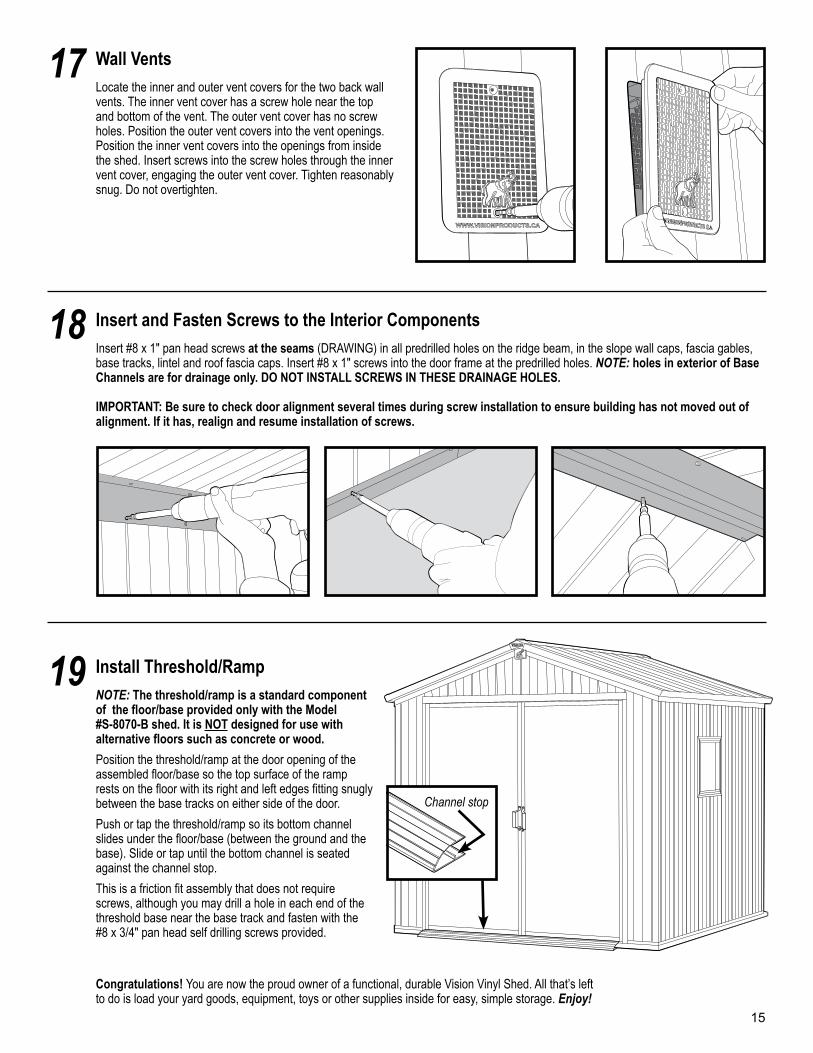
Wall VentsLocate the inner and outer vent covers for the two back wall vents. The inner vent cover has a screw hole near the top and bottom of the vent. The outer vent cover has no screw holes. Position the outer vent covers into the vent openings. Position the inner vent covers into the openings from inside the shed. Insert screws into the screw holes through the inner vent cover, engaging the outer vent cover. Tighten reasonably snug. Do not overtighten.
17
Insert and Fasten Screws to the Interior ComponentsInsert #8 x 1" pan head screws at the seams (DRAWING) in all predrilled holes on the ridge beam, in the slope wall caps, fascia gables, base tracks, lintel and roof fascia caps. Insert #8 x 1" screws into the door frame at the predrilled holes. NOTE: holes in exterior of Base Channels are for drainage only. DO NOT INSTALL SCREWS IN THESE DRAINAGE HOLES.
IMPORTANT: Be sure to check door alignment several times during screw installation to ensure building has not moved out of alignment. If it has, realign and resume installation of screws.
18
15
Install Threshold/RampNOTE: The threshold/ramp is a standard component of the floor/base provided only with the Model #S-8070-B shed. It is NOT designed for use with alternative floors such as concrete or wood.
Position the threshold/ramp at the door opening of the assembled floor/base so the top surface of the ramp rests on the floor with its right and left edges fitting snugly between the base tracks on either side of the door.
Push or tap the threshold/ramp so its bottom channel slides under the floor/base (between the ground and the base). Slide or tap until the bottom channel is seated against the channel stop.
This is a friction fit assembly that does not require screws, although you may drill a hole in each end of the threshold base near the base track and fasten with the #8 x 3/4" pan head self drilling screws provided.
19
Channel stop
Congratulations! You are now the proud owner of a functional, durable Vision Vinyl Shed. All that’s left to do is load your yard goods, equipment, toys or other supplies inside for easy, simple storage. Enjoy!
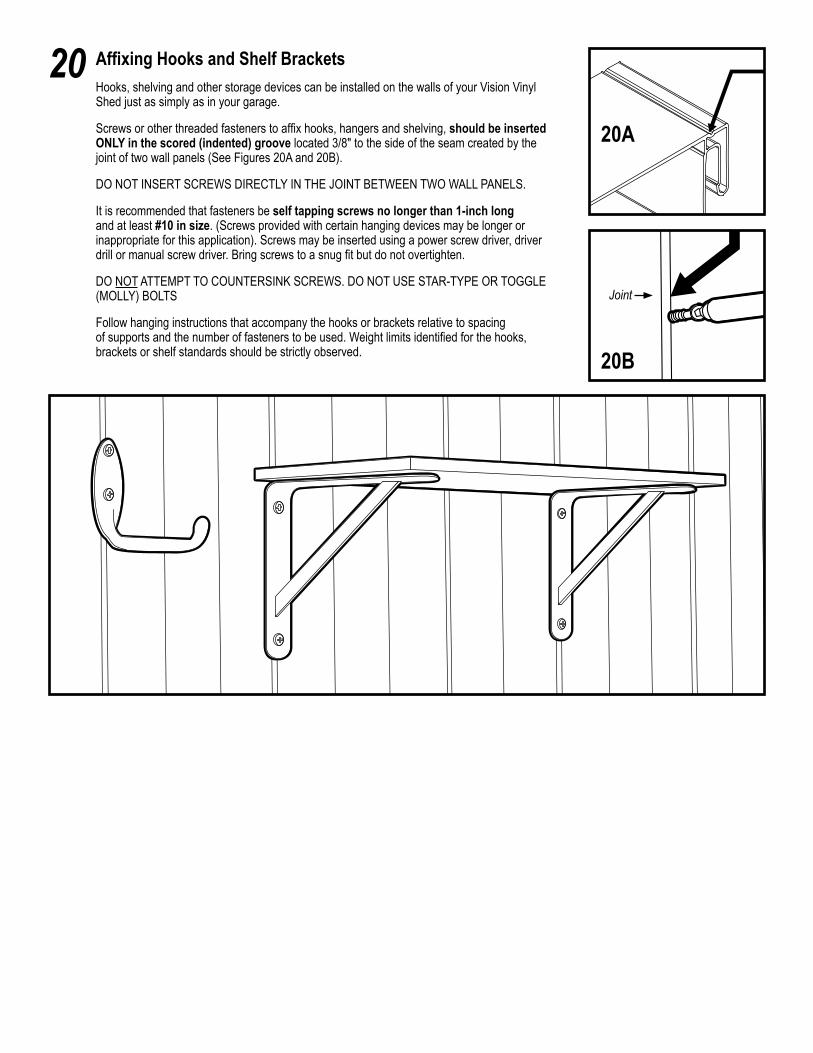
Affixing Hooks and Shelf BracketsHooks, shelving and other storage devices can be installed on the walls of your Vision Vinyl Shed just as simply as in your garage.
Screws or other threaded fasteners to affix hooks, hangers and shelving, should be inserted ONLY in the scored (indented) groove located 3/8" to the side of the seam created by the joint of two wall panels (See Figures 20A and 20B).
DO NOT INSERT SCREWS DIRECTLY IN THE JOINT BETWEEN TWO WALL PANELS.
It is recommended that fasteners be self tapping screws no longer than 1-inch long and at least #10 in size. (Screws provided with certain hanging devices may be longer or inappropriate for this application). Screws may be inserted using a power screw driver, driver drill or manual screw driver. Bring screws to a snug fit but do not overtighten.
DO NOT ATTEMPT TO COUNTERSINK SCREWS. DO NOT USE STAR-TYPE OR TOGGLE (MOLLY) BOLTS
Follow hanging instructions that accompany the hooks or brackets relative to spacing of supports and the number of fasteners to be used. Weight limits identified for the hooks, brackets or shelf standards should be strictly observed.
20
20A
20B
Joint