8-Port Asynchronous ISA Adapter Installation and...
42
IBM 8-Port Asynchronous ISA Adapter Installation and User's Guide
Transcript of 8-Port Asynchronous ISA Adapter Installation and...

IBM
8-Port Asynchronous ISA AdapterInstallation and User's Guide


IBM
8-Port Asynchronous ISA AdapterInstallation and User's Guide

Note
Before using this information and the product it supports, be sure to read the generalinformation under "Product Warranties and Notices" included with your system unit.
Third Edition (November 1996)
The following paragraph does not apply to the United Kingdom or any country wheresuch provisions are inconsistent with local law: THIS PUBLICATION IS PROVIDED “ASIS” WITHOUT WARRANTY OF ANY KIND, EITHER EXPRESS OR IMPLIED, INCLUDING,BUT NOT LIMITED TO, THE IMPLIED WARRANTIES OF MERCHANTABILITY OR FITNESSFOR A PARTICULAR PURPOSE. Some states do not allow disclaimer of express or impliedwarranties in certain transactions, therefore, this statement may not apply to you.
This publication could include technical inaccuracies or typographical errors. Changes areperiodically made to the information herein; these changes will be incorporated in new editionsof the publication. The manufacturer may make improvements and/or changes in theproduct(s) and/or the program(s) described in this publication at any time, without notice.
It is possible that this publication may contain reference to, or information about, products(machines and programs), programming, or services that are not announced in your country.Such references or information must not be construed to mean that these products,programming, or services will be announced in your country. Any reference to a specificlicensed program in this publication is not intended to state or imply that you can use only thatlicensed program. You can use any functionally equivalent program instead.
Requests for technical information about products should be made to your authorized reselleror marketing representative.
International Business Machines Corporation 1995, 1996. All rights reserved.Note to U.S. Government Users -- Documentation related to restricted rights -- Use,duplication or disclosure is subject to restrictions set forth is GSA ADP Schedule Contract withIBM Corp.

Contents
Safety Information . . . . . . . . . . . . . . . . . . . . . . . . . . . . . . . . . . . . . v
About This Book . . . . . . . . . . . . . . . . . . . . . . . . . . . . . . . . . . . . . . viiRelated Publications . . . . . . . . . . . . . . . . . . . . . . . . . . . . . . . . . . . . viiISO 9000 . . . . . . . . . . . . . . . . . . . . . . . . . . . . . . . . . . . . . . . . . . . viiTrademarks . . . . . . . . . . . . . . . . . . . . . . . . . . . . . . . . . . . . . . . . . vii
Chapter 1. Overview . . . . . . . . . . . . . . . . . . . . . . . . . . . . . . . . . . 1-1Installation Requirements . . . . . . . . . . . . . . . . . . . . . . . . . . . . . . . . 1-18-Port Asynchronous Adapter Package . . . . . . . . . . . . . . . . . . . . . . . . 1-1Handling the Adapter . . . . . . . . . . . . . . . . . . . . . . . . . . . . . . . . . . . 1-1
Chapter 2. Hardware Configuration and Installation . . . . . . . . . . . . . . . 2-1Configuring the Adapter . . . . . . . . . . . . . . . . . . . . . . . . . . . . . . . . . 2-1Installing the Adapter . . . . . . . . . . . . . . . . . . . . . . . . . . . . . . . . . . . 2-3
Chapter 3. Installing, Configuring, and Verifying Software . . . . . . . . . . 3-1AIX Software Installation . . . . . . . . . . . . . . . . . . . . . . . . . . . . . . . . . 3-1AIX Software Configuration . . . . . . . . . . . . . . . . . . . . . . . . . . . . . . . 3-2Verifying Device Driver Installation . . . . . . . . . . . . . . . . . . . . . . . . . . . 3-3Diagnostics . . . . . . . . . . . . . . . . . . . . . . . . . . . . . . . . . . . . . . . . . 3-3Windows NT (PowerPC Edition) Device Driver Installation - Version 3.51 . . . . 3-4Windows NT (PowerPC Edition) Device Driver Installation - Version 4.0 . . . . . 3-5Memory Window Size and Starting Address . . . . . . . . . . . . . . . . . . . . . . 3-5
Appendix A. Connectors and Cables . . . . . . . . . . . . . . . . . . . . . . . . A-1Connectors for the 8-Port Asynchronous EIA-232E adapter . . . . . . . . . . . . . A-1Connectors for the 8-Port Asynchronous EIA-232E/RS-422A Adapter . . . . . . . A-2Capacitance vs. Length of Run . . . . . . . . . . . . . . . . . . . . . . . . . . . . . A-3Connecting to a DTE Device . . . . . . . . . . . . . . . . . . . . . . . . . . . . . . . A-4
Appendix B. Handshaking . . . . . . . . . . . . . . . . . . . . . . . . . . . . . . . B-1Software Handshaking (XON/XOFF) . . . . . . . . . . . . . . . . . . . . . . . . . . B-1Hardware Handshaking (Ready/Busy) . . . . . . . . . . . . . . . . . . . . . . . . . B-5
Appendix C. Specifications for the 8-Port Asynchronous ISA Adapters . . C-1
Appendix D. Using the AIX lsresource Command . . . . . . . . . . . . . . . . D-1Using the AIX lsresource Command for Bus I/O Addresses . . . . . . . . . . . . . D-1
Appendix E. Communications Statements . . . . . . . . . . . . . . . . . . . . . E-1
Contents iii

Federal Communications Commission (FCC) Statement . . . . . . . . . . . . . . E-1European Union (EU) Statement . . . . . . . . . . . . . . . . . . . . . . . . . . . . E-2International Electrotechnical Commission (IEC) Statement . . . . . . . . . . . . . E-2United Kingdom Telecommunications Safety Requirements . . . . . . . . . . . . . E-2Avis de conformité aux normes du ministère des Communications du Canada . E-4Canadian Department of Communications Compliance Statement . . . . . . . . . E-4VCCI Statement . . . . . . . . . . . . . . . . . . . . . . . . . . . . . . . . . . . . . . E-4Radio Protection for Germany . . . . . . . . . . . . . . . . . . . . . . . . . . . . . . E-4
iv 8-Port Asynchronous ISA Adapter Installation and User's Guide

Safety Information
DANGER
An electrical outlet that is not correctly wired could place hazardousvoltage on metal parts of the system or the devices that attach to thesystem. It is the responsibility of the customer to ensure that the outletis correctly wired and grounded to prevent an electrical shock.
Before installing or removing signal cables, ensure that the powercables for the system unit and all attached devices are unplugged.
When adding or removing any additional devices to or from the system,ensure that the power cables for those devices are unplugged beforethe signal cables are connected. If possible, disconnect all powercables from the existing system before you add a device.
Use one hand, when possible, to connect or disconnect signal cablesto prevent a possible shock from touching two surfaces with differentelectrical potentials.
During an electrical storm, do not connect cables for display stations,printers, telephones, or station protectors for communication lines.
Safety Information v

vi 8-Port Asynchronous ISA Adapter Installation and User's Guide

About This Book
This book, when used with your system unit documentation, helps you install eitherof the 8-Port Asynchronous ISA Adapters. It also provides information needed forinstalling and configuring the necessary software device drivers and for verifying thatinstallation and configuration were successfully completed.
Related Publications
This book refers to the documentation that came with your system unit.
ISO 9000
ISO 9000 registered quality systems were used in the development andmanufacturing of this product.
Trademarks
AIX is a registered trademark of International Business Machines Corporation.
PowerPC is a trademark of International Business Machines Corporation.
Windows NT is a trademark of Microsoft Corporation.
About This Book vii

viii 8-Port Asynchronous ISA Adapter Installation and User's Guide

Chapter 1. Overview
The 8-Port Asynchronous ISA Adapters are multi-channel intelligent serialcommunications adapters.
The adapters contain 128KB (kilobytes) of dual-ported high-speed RAM used forprogram code and data buffering. The ISA adapters support speeds of up to115Kbps (kilobits per second) for each asynchronous port and is run by a 32-bit 16MHz IDT 3041 processor.
The dual-ported RAM memory is accessible for read and write operations by both theadapter and the system unit. The system unit sees the dual-ported RAM as its ownmemory and accesses it by the same high-speed memory referencing commands ituses for its internal memory.
Installation Requirements
� 8-Port Asynchronous Adapter Package� AIX CD (if no diskette is furnished with the 8-Port Adapter Package)� The User's Guide that came with your system� Flat blade screw driver.
8-Port Asynchronous Adapter Package
The 8-Port Asynchronous ISA Adapter package contains the following items:
� 8-Port asynchronous adapter� 8-Port Asynchronous Cable with Fan-out Box or Connector assembly� Optional media containing device driver or diagnostic software for the 8-Port
Asynchronous ISA Adapter� 8-port Asynchronous Adapter Installation and User's Guide (this manual).
Handling the Adapter
Attention: Static electricity can damage your equipment. Leave the adapter in thestatic-protective bag until you are ready to configure or install it.
Chapter 1. Overview 1-1

1-2 8-Port Asynchronous ISA Adapter Installation and User's Guide
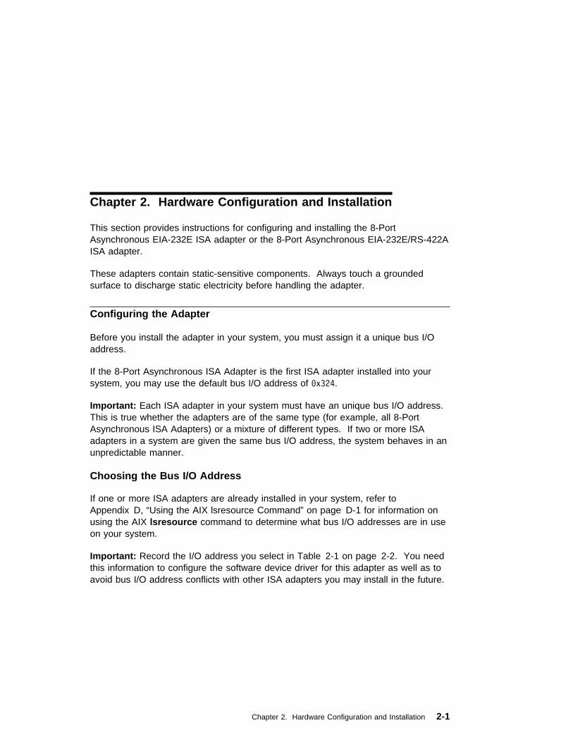
Chapter 2. Hardware Configuration and Installation
This section provides instructions for configuring and installing the 8-PortAsynchronous EIA-232E ISA adapter or the 8-Port Asynchronous EIA-232E/RS-422AISA adapter.
These adapters contain static-sensitive components. Always touch a groundedsurface to discharge static electricity before handling the adapter.
Configuring the Adapter
Before you install the adapter in your system, you must assign it a unique bus I/Oaddress.
If the 8-Port Asynchronous ISA Adapter is the first ISA adapter installed into yoursystem, you may use the default bus I/O address of ðx324.
Important: Each ISA adapter in your system must have an unique bus I/O address.This is true whether the adapters are of the same type (for example, all 8-PortAsynchronous ISA Adapters) or a mixture of different types. If two or more ISAadapters in a system are given the same bus I/O address, the system behaves in anunpredictable manner.
Choosing the Bus I/O Address
If one or more ISA adapters are already installed in your system, refer toAppendix D, “Using the AIX lsresource Command” on page D-1 for information onusing the AIX lsresource command to determine what bus I/O addresses are in useon your system.
Important: Record the I/O address you select in Table 2-1 on page 2-2. You needthis information to configure the software device driver for this adapter as well as toavoid bus I/O address conflicts with other ISA adapters you may install in the future.
Chapter 2. Hardware Configuration and Installation 2-1

Setting the Bus I/O Address
Configure the bus I/O address you select by setting the switches on the rear of theadapter as shown in Figure 2-1. A switch is ON when it points towards the numberslabeled on the switch.
If you are using the default address for the first ISA adapter (0x324), all four switchesare set to ON.
You may set the switches to the address you select before or after you install theadapter into your system.
Figure 2-1. Bus I/O Address Switch Settings
Note:
� Address 0x324 is the default address set at the factory.
� The maximum of seven adapters is defined as any combination of seven8-Port Asynchronous EIA-232E and 8-Port AsynchronousEIA-232E/RS-422A adapters together. This is because the two adaptertypes use the same seven Bus I/O Address ranges.
Table 2-1. ISA Bus I/O Addresses
ISA Adapter Description Bus I/O Address
8-Port Async 0x_____________
0x_____________
0x_____________
0x_____________
0x_____________
2-2 8-Port Asynchronous ISA Adapter Installation and User's Guide

Installing the Adapter
To install the 8-Port Asynchronous ISA adapter, follow these steps:
1. Refer to your system unit documentation for instructions on shutting down thesystem, removing the covers, and installing ISA adapters. Shutdown yoursystem unit, turn off its power, and remove the covers.
2. Locate an available ISA slot in your system unit and remove the slot plate.
3. Plug the 8-Port Asynchronous ISA adapter into the slot, and screw the endplateto the system unit chassis using the screw you removed from the slot plate. Theadapter endplate must be screwed to the system unit chassis for the system toremain in compliance with Part 15 of the FCC rules.
4. Replace your system unit's covers according to your system unit documentation.
5. Connect the 8-Port Asynchronous cable with fan-out box to the adapter.
0 1 2 3 4 5 6 7
Figure 2-2. 8-Port Asynchronous cable with fan-out Box
Figure 2-3. 8-Port Asynchronous EIA-232E Adapter
Chapter 2. Hardware Configuration and Installation 2-3

Figure 2-4. 8-Port Asynchronous EIA-232E/RS-422A Adapter
Note: There are componenets on the back side of the 8-Port AsynchronousEIA-232E/RS-422A Adapter.
Refer to the following sections for cabling, handshaking, and specifications for the8-Port Asynchronous ISA Adapters:
� Appendix A, “Connectors and Cables” on page A-1
� Appendix B, “Handshaking” on page B-1
� Appendix C, “Specifications for the 8-Port Asynchronous ISA Adapters” onpage C-1.
You are now ready to install the software and can proceed to Chapter 3, “ Installing,Configuring, and Verifying Software” on page 3-1.
2-4 8-Port Asynchronous ISA Adapter Installation and User's Guide
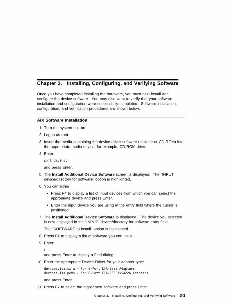
Chapter 3. Installing, Configuring, and Verifying Software
Once you have completed installing the hardware, you must next install andconfigure the device software. You may also want to verify that your softwareinstallation and configuration were successfully completed. Software installation,configuration, and verification procedures are shown below.
AIX Software Installation
1. Turn the system unit on.
2. Log in as root.
3. Insert the media containing the device driver software (diskette or CD-ROM) intothe appropriate media device, for example, CD-ROM drive.
4. Enter:
smit devinst
and press Enter.
5. The Install Additional Device Software screen is displayed. The "INPUTdevice/directory for software" option is highlighted.
6. You can either:
� Press F4 to display a list of input devices from which you can select theappropriate device and press Enter.
� Enter the input device you are using in the entry field where the cursor ispositioned.
7. The Install Additional Device Software is displayed. The device you selectedis now displayed in the "INPUT" device/directory for software entry field.
The "SOFTWARE to install" option is highlighted.
8. Press F4 to display a list of software you can install.
9. Enter:
/and press Enter to display a Find dialog.
10. Enter the appropriate Device Driver for your adapter type:
devices.isa.cxia - For 8-Port EIA-232E Adapters
devices.isa.pc8s - For 8-Port EIA-232E/RS422A Adapters
and press Enter.
11. Press F7 to select the highlighted software and press Enter.
Chapter 3. Installing, Configuring, and Verifying Software 3-1

12. The Install Additional Device Software screen is displayed with the requiredfields filled in. Press Enter.
13. The ARE YOU SURE list is displayed. Press Enter.
14. The following occurs when the COMMAND STATUS screen is displayed:
� The term RUNNING is highlighted to indicate that the install and configurecommand is in progress.
� When RUNNING changes into OK, scroll down to the bottom of the page andlocate the Installation Summary.
� At the bottom of the page, if the installation was successful, SUCCESS appearsin the Result column of this summary.
15. Remove the installation media from the drive.
16. Press F10 to exit SMIT.
Proceed with the next section.
AIX Software Configuration
1. Enter:
smit isa
2. On the ISA Adapters screen, select "Add an ISA Adapter" and press Enter. TheAdd an ISA Adapter screen displays.
3. Select "8-Port Async, EIA-232E or EIA-232E/RS-422A (ISA)" and press Enter. The Parent Device screen displays.
4. Select "bus1" and press Enter. The Add an 8-Port Async, EIA-232E orEIA-232E/RS-422A (ISA) Adapter screen displays.
You can use the default values for all information required for this screen exceptBus I/O Address.
5. Press F4 for a list of available Bus I/O Addresses. Select the bus I/O address tomatch the switch settings on the adapter recorded in Table 2-1 on page 2-2.
Important: If you select a different address while configuring the softwarewithout changing the bus I/O address switches on the adapter, your system willnot function correctly.
3-2 8-Port Asynchronous ISA Adapter Installation and User's Guide

6. All required information is now entered on this screen. Press Enter.
7. The COMMAND STATUS screen displays while the software installationcommand is being run. When command status changes from RUNNING to OK, thesoftware configuration procedure is complete.
If an error message displays on the COMMAND STATUS screen, refer toAppendix D, “Using the AIX lsresource Command” on page D-1 as a troubleshooting aid.
8. Press F10 to exit smit.
You may now proceed with verifying your newly installed ISA device. There isno need to shutdown or reboot your system.
Verifying Device Driver Installation
To verify that your newly installed 8-Port Asynchronous ISA Adapter is available foruse, follow the steps below:
1. At the prompt, type the following and press Enter.
lsdev -Cs isa
2. A list of ISA devices displays. Verify that the 8-Port Asynchronous ISA Adapteris in Available mode.
If the 8-Port Asynchronous ISA Adapter registers Available, your installation is readyto use.
Diagnostics
Diagnostics may be supplied with your device driver, or may be found in a separatepackage. Refer to your system unit documentation for more information aboutrunning diagnostics.
Chapter 3. Installing, Configuring, and Verifying Software 3-3

Windows NT (PowerPC Edition) Device Driver Installation - Version 3.51
1. Log on to Windows NT (PowerPC Edition) as an Administrator.
2. Double-click on the Main program group icon.
3. Double-click on the Control Panel icon.
If the Control Panel icon is missing, type control on a command line to initiatethe program directly. To get to a command line prompt, select the MS DOScommand prompt icon.
4. Double-click on the Network icon.
On this window there is a Network Software and Adapter Cards area thatcontains an INSTALLED NETWORK SOFTWARE list and an INSTALLEDADAPTER CARDS list. When you have finished the installation, this bottom listshould contain entries for the adapter you have installed.
5. Click on Add Adapter (not Add Software ).
The message Setup is preparing network card choices displays in a window.This may take 10 to 30 seconds, depending on your configuration.
6. Select IBM 8-Port Async EIA-232, ISA adapter . Click on Continue .
7. When asked for a path for the driver software, enter the letter of the drive fromwhich you installed the &wnt. software. Click on Continue .
8. Fill in the information requested in the dialog boxes. Refer to the help screens inthe configuration dialog boxes, and the information in the adapter's installationguide for switch settings and supported interrupt levels. For memory windowsize and starting addresses, refer to “Memory Window Size and StartingAddress” on page 3-5.
9. Click on OK.
The NETWORK SETTINGS panel displays again. This time an entry for theadapter you have just added appears in the INSTALLED ADAPTER CARDS listbox.
Click on the OK button at the top right of this window to complete the installation.
10. A message displays indicating that you need to shutdown and reboot. Click onRestart now .
3-4 8-Port Asynchronous ISA Adapter Installation and User's Guide

Windows NT (PowerPC Edition) Device Driver Installation - Version 4.0
1. Log on to Windows NT (PowerPC Edition) as an Administrator.
2. Double-click on the My Computer icon.
3. Double-click on the Control Panel icon.
4. Double-click on the Network icon.
5. Select Adapters .
6. Select Add .
7. Insert the Windows NT (PowerPC Edition) CD-ROM into the CD-ROM drive andselect Have Disk .
8. Enter the path for the CD-ROM drive and press OK.
9. Scroll through the adapter list, select IBM 8-Port Async, EIA-232 (ISA) Adapter .
10. Press OK.
The driver now installs and the changes are saved. Upon completion, you mustshutdown and restart your system unit before the new settings take effect.
Memory Window Size and Starting Address
The memory window size and starting address are programmed into the board bythe device driver. No switches or jumpers are required to change these parameters.
The 8-port adapter requires 32K bytes of unused memory address space in yoursystem unit. This is usually allocated from the area between 0C0000h and 0EFFFFhin your system unit's memory map. Before deciding on a memory start address,remember that the 8-port adapter may have to coexist with a number of otherdevices that also require memory address space. You may have to try a number ofdifferent starting addresses before you find a free area. The starting addresses for32K windows between 0C0000h and 0EFFFFh are 0C0000h, 0C8000h, 0D0000h,0D8000h, 0E0000h and 0E8000h. You can also run the WINMSD program to helpfind open memory address ranges.
Note: If you are installing more than one 8-port adapter, they can all share thesame starting address.
Chapter 3. Installing, Configuring, and Verifying Software 3-5

3-6 8-Port Asynchronous ISA Adapter Installation and User's Guide

Appendix A. Connectors and Cables
There are two types of 8-Port Asynchronous ISA adapters. There is the 8-PortAsynchronous EIA-232E adapter and the 8-Port Asynchronous EIA-232E/RS-422Aadapter. The 8-Port Asynchronous EIA-232E adapter supports only the EIA-232Ecommunications devices. The 8-Port Asynchronous EIA-232E/RS-422A adaptersupports both EIA-232E communications devices and the RS-422A communicationsdevices. Each port on the 8-Port Asynchronous EIA-232E/RS-422A adapter can beset by software to support either EIA-232E or RS-422A. The connectors on theseadapters look the same but have different signals on the pins when the RS-422Ainterface is being used.
Connectors for the 8-Port Asynchronous EIA-232E adapter
The 8-Port Asynchronous EIA-232E adapter is shipped with a cable and attachedfan-out box or connector box that provides eight DB-25 standard connectors. Thepin assignments for the male DB-25 connectors follow the EIA-232E DTE interfacestandard. The following table shows the DB-25 connector pin assignments forEIA-232E Applications.
Table A-1. DB-25 Connectors for EIA-232E Applications
Signal Description Use Pin Number
GND Chassis Ground N/A Shell
TxD Transmitted Data Output 2
RxD Received Data Input 3
RTS Request to Send Output 4
CTS Clear to Send Input 5
DSR Data Set Ready Input 6
SG Signal Ground Reference 7
DCD Data Carrier Detect Input 8
DTR Data Terminal Ready Output 20
RI Ring Indicator Input 22
Appendix A. Connectors and Cables A-1

Connectors for the 8-Port Asynchronous EIA-232E/RS-422A Adapter
The 8-Port Asynchronous EIA-232E/RS-422A adapter is shipped with a cable andattached fan-out box or connector box that provides eight DB-25 standardconnectors. The pin assignments for the male DB-25 connectors for the EIA-232Einterface follow the EIA-232E DTE interface standard. The pin assignments for themale DB-25 connectors for the EIA-232E applications are shown in Table A-1 onpage A-1. The following table shows the DB-25 connector pin assignments forRS-422A applications.
Table A-2. DB-25 Connectors for RS-422A Applications
Signal Description Use Pin Number
GND Chassis Ground N/A Shell
TxDb Transmitted Data b Output 2
RxDb Received Data b Input 3
TxDa Transmitted Data a Output 4
RxDa Received Data a Input 5
DSR Data Set Ready Input 6
SG Signal Ground Reference 7
DCD Data Carrier Detect Input 8
DTR Data Terminal Ready Output 20
Cables
EIA-232E and RS-422A serial interface cables should be shielded, low-capacitancecables. Ideally, they should be designed specifically for serial data transmission.
Grounding
The shield should be grounded at both ends of the cable. Chassis Ground, availableon the shell of the DB-25 connector, is ideal for this purpose.
Environment
While good shielding provides reasonable protection against noise (electromagneticinterference, or EMI), cables should still be routed away from noise sources whereverpossible. Avoid laying cables in close proximity to transformers, generators, motors,fluorescent lights, or other electrical noise-producing equipment.
A-2 8-Port Asynchronous ISA Adapter Installation and User's Guide

Capacitance vs. Length of Run
The total capacitance of a cable affects the integrity of transmitted data. As ageneral rule, the total capacitance of a cable (including the connectors) should notexceed 2500 pF for baud rates of up to 57,600 (1200 pF for 115K baud and 600 pFfor 230K baud). Serial interface cable is usually rated in picofarads per foot (pF/ft).Therefore, if a cable has a capacitance of 50 pF/ft, and the connectors are 100 pFeach, the maximum recommended cable length is 46 feet for baud rates of up to57,600. If the cable is rated at 12.5 pF/ft, the maximum recommended cable lengthis 184 feet, and 5 pF/ft cable can be run up to 460 feet.
Asynchronous Cable Connectors
All of the asynchronous cables described below have the same connectors. In eachcase the end that goes to the system has a 25 pin D shell with sockets (female).The end that goes to the device has a 25 pin D shell with pins (male). The figurebelow shows the ends of the 25 pin connectors. The system end is on the left andthe device end is on the right.
System End (Female) Device End (Male)
POS 1POS 14
POS 1POS 14
Figure A-1. Asynchronous Cable Connectors
Appendix A. Connectors and Cables A-3
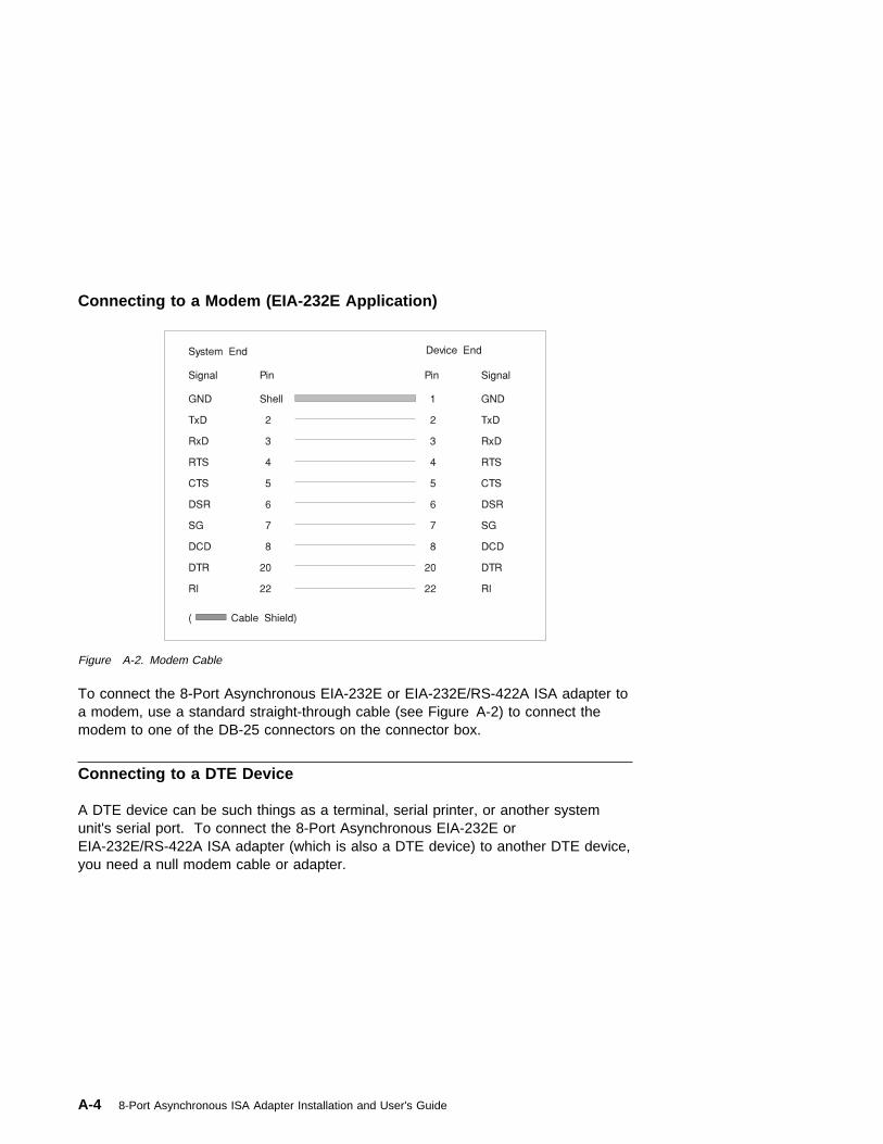
Connecting to a Modem (EIA-232E Application)
Figure A-2. Modem Cable
To connect the 8-Port Asynchronous EIA-232E or EIA-232E/RS-422A ISA adapter toa modem, use a standard straight-through cable (see Figure A-2) to connect themodem to one of the DB-25 connectors on the connector box.
Connecting to a DTE Device
A DTE device can be such things as a terminal, serial printer, or another systemunit's serial port. To connect the 8-Port Asynchronous EIA-232E orEIA-232E/RS-422A ISA adapter (which is also a DTE device) to another DTE device,you need a null modem cable or adapter.
A-4 8-Port Asynchronous ISA Adapter Installation and User's Guide

Appendix B. Handshaking
Software Handshaking (XON/XOFF)
In most cases, serial terminals and printers need only a three-signal connection toeither 8-Port Asynchronous ISA Adapter. For device drivers that support XON/XOFF(software) handshaking, the only required signal lines are transmitted data (TxD),received data (RxD), and signal ground (SG). Cables must be shielded to remain incompliance with FCC certification requirements, and the shield must be connected tochassis ground (GND) at both ends of the cable run. It can be used for a nullmodem cable (for example, transmitted data on one end of the cable is connected toreceived data at the other end, and vice versa). A cable of this type is shown inFigure B-1 for EIA-232E applications.
Figure B-1. Simple Terminal/Printer Cable for EIA-232E Applications
Appendix B. Handshaking B-1
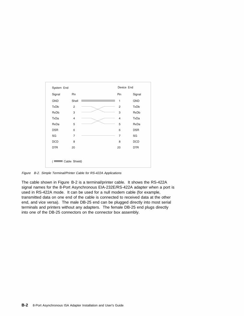
Figure B-2. Simple Terminal/Printer Cable for RS-422A Applications
The cable shown in Figure B-2 is a terminal/printer cable. It shows the RS-422Asignal names for the 8-Port Asynchronous EIA-232E/RS-422A adapter when a port isused in RS-422A mode. It can be used for a null modem cable (for example,transmitted data on one end of the cable is connected to received data at the otherend, and vice versa). The male DB-25 end can be plugged directly into most serialterminals and printers without any adapters. The female DB-25 end plugs directlyinto one of the DB-25 connectors on the connector box assembly.
B-2 8-Port Asynchronous ISA Adapter Installation and User's Guide

Figure B-3. Terminal/Printer Cable for EIA-232E Applications
The cable shown in Figure B-3 is a terminal/printer cable that can be used forvarious hardware and software protocols. It can be used for a null modem cable (forexample, transmitted data on one end of the cable is connected to received data atthe other end, and vice versa). The male DB-25 end can be plugged directly intomost serial terminals and printers without any adapters. The female DB-25 endplugs directly into one of the DB-25 connectors on the connector box assembly.
Appendix B. Handshaking B-3

Figure B-4. Terminal/Printer Cable for RS-422A Applications
The cable shown in Figure B-4 is a terminal/printer cable. It shows the RS-422Asignal names for the 8-Port Asynchronous EIA-232E/RS-422A adapter when a port isused in RS-422A mode. It can be used for a null modem cable (for example,transmitted data on one end of the cable is connected to received data at the otherend, and vice versa). The male DB-25 end can be plugged directly into most serialterminals and printers without any adapters. The female DB-25 end plugs directlyinto one of the DB-25 connectors on the connector box assembly.
B-4 8-Port Asynchronous ISA Adapter Installation and User's Guide

Hardware Handshaking (Ready/Busy)
Figure B-5. Terminal/Printer Cable with DTR Handshaking EIA-232E Applications
Most terminals and printers use data terminal ready (DTR) for ready/busy hardwarehandshaking. The cable shown in Figure B-5 supports this method and can becustom built.
Some printers use a control signal on pin 11, called supervisory send data (SSD)instead of DTR. In this case, simply connect CTS on the female DB-25 side to pin11 of the male DB-25, instead of pin 20. Other printer manufacturers may usedifferent methods of flow control. Consult your printers documentation for specificwiring requirements.
Appendix B. Handshaking B-5

B-6 8-Port Asynchronous ISA Adapter Installation and User's Guide
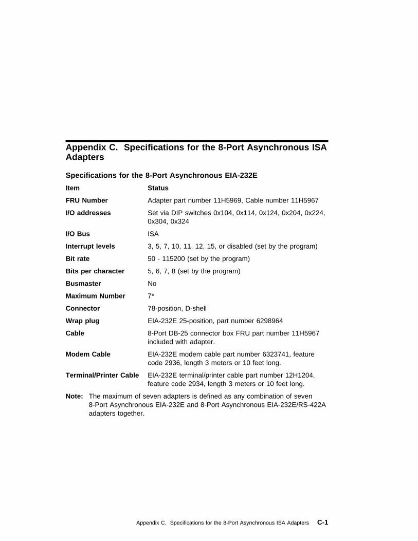
Appendix C. Specifications for the 8-Port Asynchronous ISAAdapters
Specifications for the 8-Port Asynchronous EIA-232E
Item Status
FRU Number Adapter part number 11H5969, Cable number 11H5967
I/O addresses Set via DIP switches 0x104, 0x114, 0x124, 0x204, 0x224,0x304, 0x324
I/O Bus ISA
Interrupt levels 3, 5, 7, 10, 11, 12, 15, or disabled (set by the program)
Bit rate 50 - 115200 (set by the program)
Bits per character 5, 6, 7, 8 (set by the program)
Busmaster No
Maximum Number 7*
Connector 78-position, D-shell
Wrap plug EIA-232E 25-position, part number 6298964
Cable 8-Port DB-25 connector box FRU part number 11H5967included with adapter.
Modem Cable EIA-232E modem cable part number 6323741, featurecode 2936, length 3 meters or 10 feet long.
Terminal/Printer Cable EIA-232E terminal/printer cable part number 12H1204,feature code 2934, length 3 meters or 10 feet long.
Note: The maximum of seven adapters is defined as any combination of seven8-Port Asynchronous EIA-232E and 8-Port Asynchronous EIA-232E/RS-422Aadapters together.
Appendix C. Specifications for the 8-Port Asynchronous ISA Adapters C-1

Specifications for the 8-Port Asynchronous EIA-232E/RS-422A
Item Status
FRU Number Adapter FRU part number 40H6632, Cable number11H5967
I/O addresses Set via DIP switches 0x104, 0x114, 0x124, 0x204, 0x224,0x304, 0x324
I/O Bus ISA
Interrupt levels 3, 5, 7, 10, 11, 12, 15, or disabled (set by the program)
Bit rate 50 - 115200 (set by the program)
Bits per character 5, 6, 7, 8 (set by the program)
Busmaster No
Maximum Number 7
Connector 78-position, D-shell
Wrap plug EIA-232E 25-position, part number 6298964
Cable 8-Port DB-25 connector box FRU part number 11H5967included with adapter.
Modem Cable EIA-232E modem cable part number 6323741, featurecode 2936, length 3 meters or 10 feet long.
Terminal/Printer Cable EIA-232E terminal/printer cable part number 30F8966,feature code 2945, length 20 meters or 65.5 feet long.
Note: The maximum of seven adapters is defined as any combination of seven8-Port Asynchronous EIA-232E and 8-Port Asynchronous EIA-232E/RS-422Aadapters together.
C-2 8-Port Asynchronous ISA Adapter Installation and User's Guide

Appendix D. Using the AIX lsresource Command
This section aids you in determining what hardware resources are available prior toinstalling an 8-Port Asynchronous ISA Adapter, or after a configuration failure due toa resource conflict.
Using the AIX lsresource Command for Bus I/O Addresses
1. Login as root
2. Enter:
lsresource -l busð -a | grep bus_io
This command generates a list of adapters installed on your system that use BusI/O Addresses. The following is a sample of what appears on your screen:
TYPE ADAPTER ATTRIBUTE S G CURRENT VALUE (bus I/O address)
O fdað bus_io_addr ðxððððð3fð - ðxððððð3f5
O fdað bus_io_addr2 ðxððððð3f7
O sað bus_io_addr ðxððððð3f8 - ðxððððð3ff
O sa1 bus_io_addr ðxððððð2f8 - ðxððððð2ff
O siokað bus_io_addr 1 ðxðððððð6ð
O siomað bus_io_addr 1 ðxðððððð6ð
O ppað bus_io_addr ðxððððð3bc - ðxððððð3be
O ampxð bus_io_addr ðxððððð2að - ðxððððð2a6
O apmð bus_io_addr ðxððððð6að - ðxððððð6a6
O scsið bus_io_addr ðxððððfððð - ðxððððfðff
O scsi1 bus_io_addr ðxð1ðððððð - ðxð1ððððff
The example shows 0x2a0 (0x000002a0) bus I/O address is in use by ampx0and just below that 0x6a0 is in use by apm0.
3. The 8-Port Asynchronous ISA Adapter requires a unique bus I/O address foreach adapter installed. Check the list on your screen to see if any of thefollowing address locations are in use: 0x104, 0x114, 0x124, 0x204, 0x224,0x304, and 0x324. If 0x324 is not in use, you may install the adapter withoutchange. Otherwise choose an unused address location.
4. Return to Table 2-1 on page 2-2 to record the bus I/O address you haveselected.
Appendix D. Using the AIX lsresource Command D-1

D-2 8-Port Asynchronous ISA Adapter Installation and User's Guide

Appendix E. Communications Statements
The following statement applies to this product. The statement for other productsintended for use with this product appears in their accompanying documentation.
Federal Communications Commission (FCC) Statement
Note: The &typemod. been tested and found to comply with the limits for a Class Bdigital device, pursuant to Part 15 of the FCC Rules. These limits are designed toprovide reasonable protection against harmful interference in a residential installation.This equipment generates, uses, and can radiate radio frequency energy and, if notinstalled and used in accordance with the instructions, may cause harmfulinterference to radio communications. However, there is no guarantee thatinterference will not occur in a particular installation. If this equipment does causeharmful interference to radio or television reception, which can be determined byturning the equipment off and on, the user is encouraged to try to correct theinterference by one or more of the following measures:
� Reorient or relocate the receiving antenna.
� Increase the separation between the equipment and receiver.
� Connect the equipment into an outlet on a circuit different from that to which thereceiver is connected.
� Consult an authorized dealer or service representative for help.
Properly shielded and grounded cables and connectors must be used in order tomeet FCC emission limits. Proper cables and connectors are available fromauthorized dealers. Neither the provider nor the manufacturer are responsible forany radio or television interference caused by using other than recommended cablesand connectors or by unauthorized changes or modifications to this equipment.Unauthorized changes or modifications could void the user's authority to operate theequipment.
This device complies with Part 15 of the FCC Rules. Operation is subject to thefollowing two conditions: (1) this device may not cause harmful interference, and (2)this device must accept any interference received, including interference that maycause undesired operation.
Appendix E. Communications Statements E-1

Responsible Party:
International Business Machines CorporationNew Orchard RoadArmonk, New York 10504Telephone: (919) 543-2193
Tested to Comply
With FCC Standards
FOR HOME OR OFFICE USE
European Union (EU) Statement
This product is in conformity with the protection requirements of EU Council Directive89/336/EEC on the approximation of the laws of the Member States relating toelectromagnetic compatibility. The manufacturer cannot accept responsibility for anyfailure to satisfy the protection requirements resulting from a non-recommendedmodification of the product, including the fitting of option cards supplied by thirdparties. Consult with your dealer or sales representative for details on your specifichardware.
This product has been tested and found to comply with the limits for Class BInformation Technology Equipment according to CISPR 22 / European Standard EN55022. The limits for Class B equipment were derived for typical residentialenvironments to provide reasonable protection against interference with licensedcommunication devices.
International Electrotechnical Commission (IEC) Statement
This product has been designed and built to comply with IEC Standard 950.
United Kingdom Telecommunications Safety Requirements
This equipment is manufactured to the International Safety Standard EN60950 andas such is approved in the UK under the General Approval NumberNS/G/1234/J/100003 for indirect connection to the public telecommunication network.
The network adapter interfaces housed within this equipment are approvedseparately, each one having its own independent approval number. These interfaceadapters, supplied by the manufacturer, do not use or contain excessive voltages.An excessive voltage is one which exceeds 70.7 V peak ac or 120 V dc. Theyinterface with this equipment using Safe Extra Low Voltages only. In order to
E-2 8-Port Asynchronous ISA Adapter Installation and User's Guide

maintain the separate (independent) approval of the manufacturer's adapters, it isessential that other optional cards, not supplied by the manufacturer, do not usemain voltages or any other excessive voltages. Seek advice from a competentengineer before installing other adapters not supplied by the manufacturer.
Appendix E. Communications Statements E-3

Avis de conformité aux normes du ministère des Communications duCanada
Cet appareil numérique de la classe B est conform à la norme NMB-003 du Canada.
Canadian Department of Communications Compliance Statement
This Class B digital apparatus complies with Canadian ICES-003.
VCCI Statement
The following is a summary of the VCCI Japanese statement in the box above.
This product is a Class B Information Technology Equipment and conforms to thestandards set by the Voluntary Control Council for Interference by InformationTechnology Equipment (VCCI). This product is aimed to be used in a domesticenvironment. When used near a radio or TV receiver, it may become the cause ofradio interference. Read the instructions for correct handling.
Radio Protection for Germany
Dieses Gerät ist berechtigt in Übereinstimmung mit dem deutschen EMVG vom9.Nov.92 das EG–Konformitätszeichen zu führen.
Der Aussteller der Konformitätserklärung ist die IBM Germany.
Dieses Gerät erfüllt die Bedingungen der EN 55022 Klasse B.
E-4 8-Port Asynchronous ISA Adapter Installation and User's Guide


IBM
Part Number: 93H3471
Printed in the United States of Americaon recycled paper containing 10%recovered post-consumer fiber.
93H3471