Guidelines for Systems and Installations for Supply of LNG as Fuel to Ships
Upload
katsoulinaCategory
view
221download
0
7/23/2019 8 Lng Fuel Supply System_tcm142-520675
http://slidepdf.com/reader/full/8-lng-fuel-supply-systemtcm142-520675 1/50
Finalised-DBAB982956Doc.ID: Revision: Status:50/ © Wärtsilä
LNG FUEL SUPPLY SYSTEM
18 June 20121 WCN FGES/ Barry Yang
7/23/2019 8 Lng Fuel Supply System_tcm142-520675
http://slidepdf.com/reader/full/8-lng-fuel-supply-systemtcm142-520675 2/50
Finalised-DBAB982956Doc.ID: Revision: Status:50/ © Wärtsilä
AGENDA
1. LNG FUEL TANK
2. LOW PRESSURE (LP) SYSTEM
3. HIGH PRESSURE (HP) SYSTEM
4. LP AND HP COMBINED SYSTEM
5. CHALLENGES
6. WHY WARTSILA HAMWORTHY
2
7/23/2019 8 Lng Fuel Supply System_tcm142-520675
http://slidepdf.com/reader/full/8-lng-fuel-supply-systemtcm142-520675 3/50
Finalised-DBAB982956Doc.ID: Revision: Status:50/ © Wärtsilä
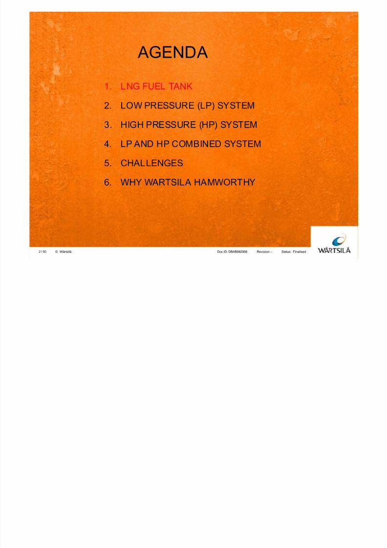
Many new designs alternatives are emerging
7/23/2019 8 Lng Fuel Supply System_tcm142-520675
http://slidepdf.com/reader/full/8-lng-fuel-supply-systemtcm142-520675 4/50
Finalised-DBAB982956Doc.ID: Revision: Status:50/ © Wärtsilä
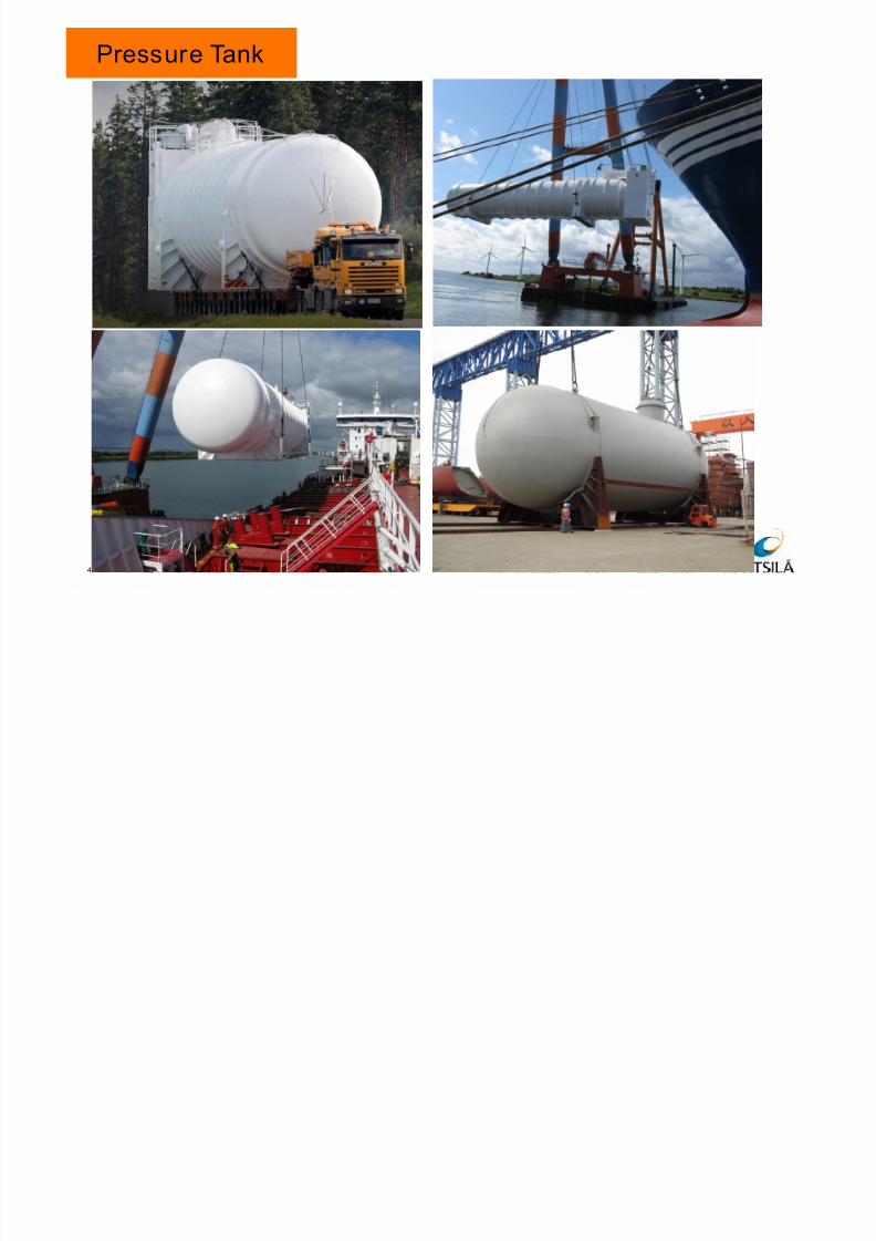
Pressure Tank
28 October 20114 Wärtsilä SOx Scrubber / M Lehikoinen
7/23/2019 8 Lng Fuel Supply System_tcm142-520675
http://slidepdf.com/reader/full/8-lng-fuel-supply-systemtcm142-520675 5/50
Finalised-DBAB982956Doc.ID: Revision: Status:50/ © Wärtsilä
AGENDA
1. LNG FUEL TANK
2. LOW PRESSURE (LP) SYSTEM
3. HIGH PRESSURE (HP) SYSTEM
4. LP AND HP COMBINED SYSTEM
5. CHALLENGES
6. WHY WARTSILA HAMWORTHY
5
7/23/2019 8 Lng Fuel Supply System_tcm142-520675
http://slidepdf.com/reader/full/8-lng-fuel-supply-systemtcm142-520675 6/50
Finalised-DBAB982956Doc.ID: Revision: Status:50/ © Wärtsilä
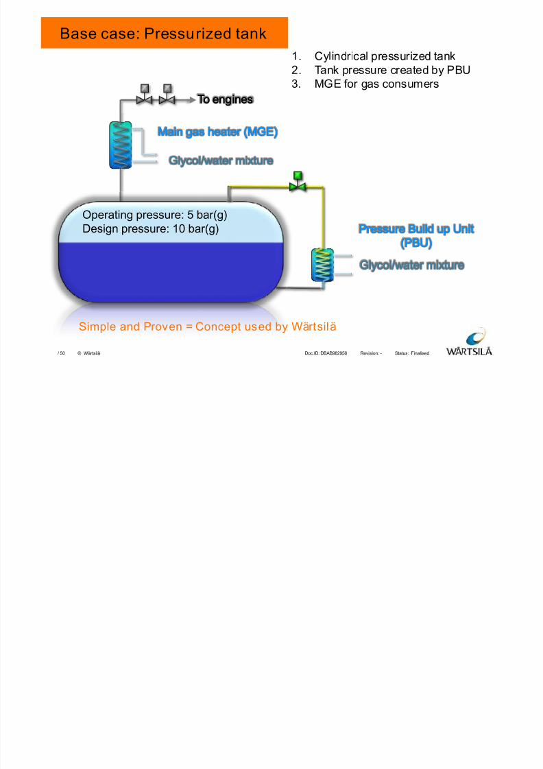
Base case: Pressurized tank
1. Cylindrical pressurized tank
2. Tank pressure created by PBU
3. MGE for gas consumers
Glycol/water mixtureGlycol/water mixture
To enginesTo engines
Pressure Build up UnitPressure Build up Unit
(PBU)(PBU)
Operating pressure: 5 bar(g)
Design pressure: 10 bar(g)
Main gas heater (MGE)Main gas heater (MGE)
Glycol/water mixtureGlycol/water mixture
Simple and Proven = Concept used by Wärtsilä
7/23/2019 8 Lng Fuel Supply System_tcm142-520675
http://slidepdf.com/reader/full/8-lng-fuel-supply-systemtcm142-520675 7/50
Finalised-DBAB982956Doc.ID: Revision: Status:50/ © Wärtsilä
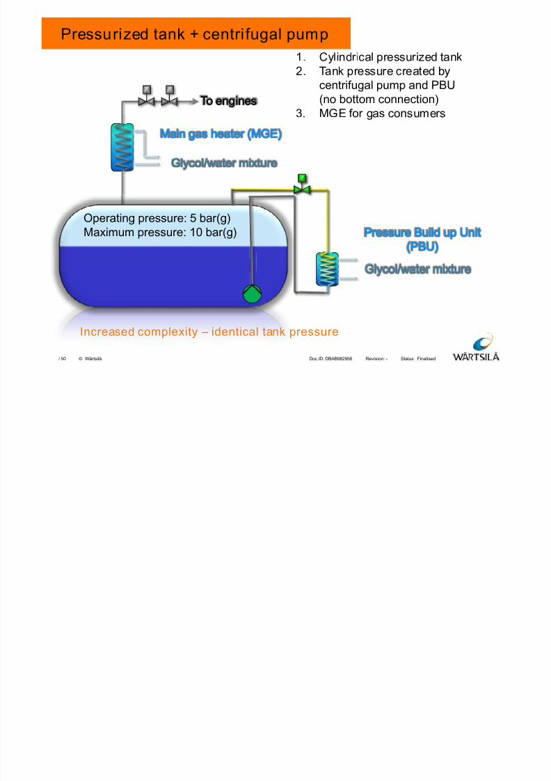
Pressurized tank + centri fugal pump
1. Cylindrical pressurized tank
2. Tank pressure created by
centrifugal pump and PBU
(no bottom connection)3. MGE for gas consumers
Glycol/water mixtureGlycol/water mixture
To enginesTo engines
Pressure Build up UnitPressure Build up Unit
(PBU)(PBU)
Operating pressure: 5 bar(g)
Maximum pressure: 10 bar(g)
Main gas heater (MGE)Main gas heater (MGE)
Glycol/water mixtureGlycol/water mixture
Increased complexity – identical tank pressure
7/23/2019 8 Lng Fuel Supply System_tcm142-520675
http://slidepdf.com/reader/full/8-lng-fuel-supply-systemtcm142-520675 8/50
Finalised-DBAB982956Doc.ID: Revision: Status:50/ © Wärtsilä
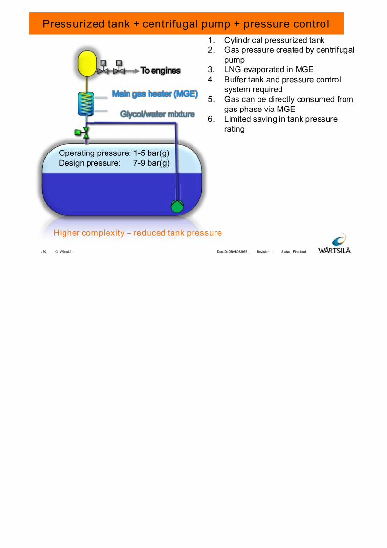
Pressurized tank + centri fugal pump + pressure control
1. Cylindrical pressurized tank
2. Gas pressure created by centrifugal
pump
3. LNG evaporated in MGE4. Buffer tank and pressure control
system required
5. Gas can be directly consumed from
gas phase via MGE
6. Limited saving in tank pressure
rating
Glycol/water mixtureGlycol/water mixture
To enginesTo engines
Operating pressure: 1-5 bar(g)
Design pressure: 7-9 bar(g)
Main gas heater (MGE)Main gas heater (MGE)
Higher complexity – reduced tank pressure
7/23/2019 8 Lng Fuel Supply System_tcm142-520675
http://slidepdf.com/reader/full/8-lng-fuel-supply-systemtcm142-520675 9/50
Finalised-DBAB982956Doc.ID: Revision: Status:50/ © Wärtsilä
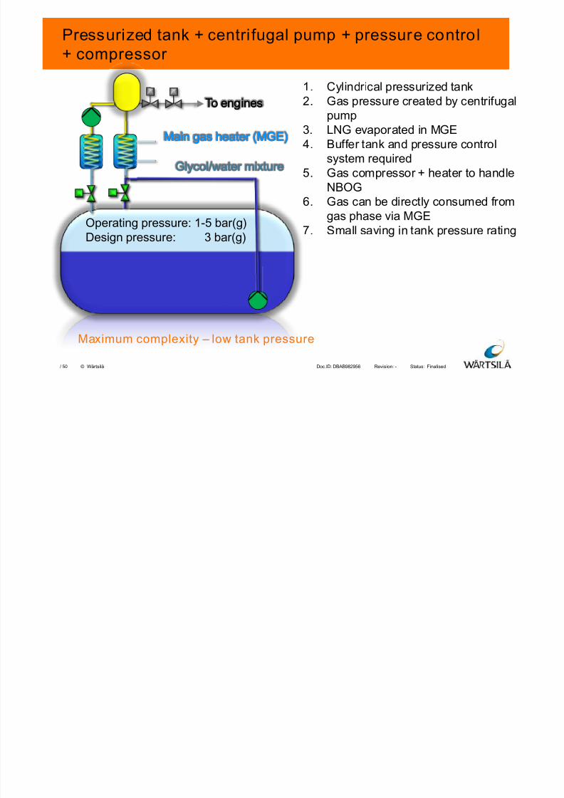
Pressurized tank + centri fugal pump + pressure control+ compressor
1. Cylindrical pressurized tank
2. Gas pressure created by centrifugalpump
3. LNG evaporated in MGE
4. Buffer tank and pressure control
system required
5. Gas compressor + heater to handle
NBOG
6. Gas can be directly consumed fromgas phase via MGE
7. Small saving in tank pressure rating
Glycol/water mixtureGlycol/water mixture
To enginesTo engines
Operating pressure: 1-5 bar(g)
Design pressure: 3 bar(g)
Main gas heater (MGE)Main gas heater (MGE)
Maximum complexity – low tank pressure
7/23/2019 8 Lng Fuel Supply System_tcm142-520675
http://slidepdf.com/reader/full/8-lng-fuel-supply-systemtcm142-520675 10/50
Finalised-DBAB982956Doc.ID: Revision: Status:50/ © Wärtsilä
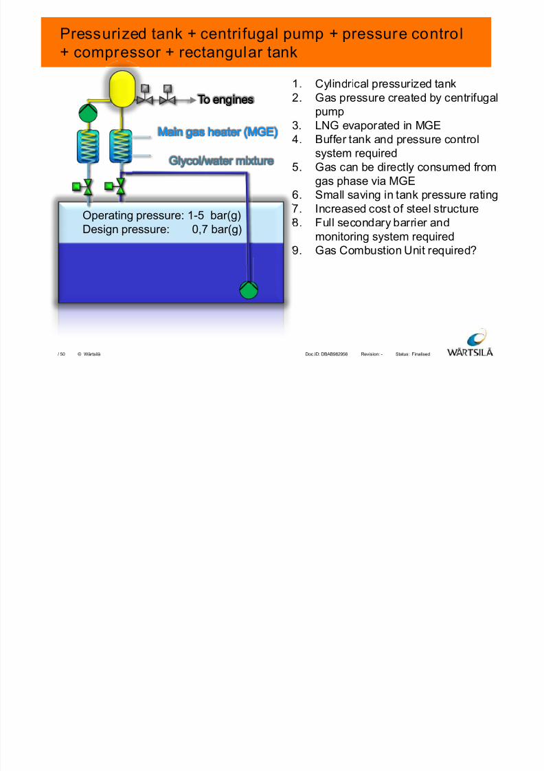
Pressurized tank + centri fugal pump + pressure control+ compressor + rectangular tank
1. Cylindrical pressurized tank
2. Gas pressure created by centrifugalpump
3. LNG evaporated in MGE
4. Buffer tank and pressure control
system required
5. Gas can be directly consumed from
gas phase via MGE
6. Small saving in tank pressure rating7. Increased cost of steel structure
8. Full secondary barrier and
monitoring system required
9. Gas Combustion Unit required?
Glycol/water mixtureGlycol/water mixture
To enginesTo engines
Operating pressure: 1-5 bar(g)
Design pressure: 0,7 bar(g)
Main gas heater (MGE)Main gas heater (MGE)
7/23/2019 8 Lng Fuel Supply System_tcm142-520675
http://slidepdf.com/reader/full/8-lng-fuel-supply-systemtcm142-520675 11/50
Finalised-DBAB982956Doc.ID: Revision: Status:50/ © Wärtsilä
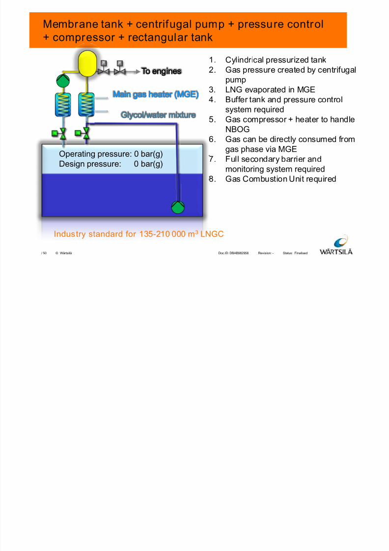
Membrane tank + centrifugal pump + pressure control+ compressor + rectangular tank
1. Cylindrical pressurized tank
2. Gas pressure created by centrifugalpump
3. LNG evaporated in MGE
4. Buffer tank and pressure control
system required
5. Gas compressor + heater to handle
NBOG
6. Gas can be directly consumed fromgas phase via MGE
7. Full secondary barrier and
monitoring system required
8. Gas Combustion Unit required
Glycol/water mixtureGlycol/water mixture
To enginesTo engines
Operating pressure: 0 bar(g)
Design pressure: 0 bar(g)
Main gas heater (MGE)Main gas heater (MGE)
Industry standard for 135-210 000 m3 LNGC
7/23/2019 8 Lng Fuel Supply System_tcm142-520675
http://slidepdf.com/reader/full/8-lng-fuel-supply-systemtcm142-520675 12/50
Finalised-DBAB982956Doc.ID: Revision: Status:50/ © Wärtsilä
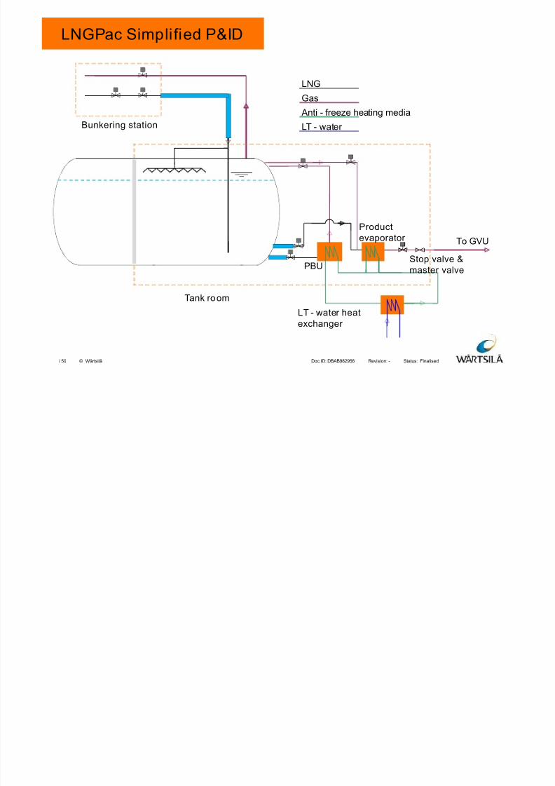
LNGPac Simplified P&ID
To GVU
Productevaporator
PBU
LNG
Gas
Anti - freeze heating media
LT - water
LT - water heatexchanger
Bunkering station
Tank room
Stop valve &master valve
7/23/2019 8 Lng Fuel Supply System_tcm142-520675
http://slidepdf.com/reader/full/8-lng-fuel-supply-systemtcm142-520675 13/50
Finalised-DBAB982956Doc.ID: Revision: Status:50/ © Wärtsilä
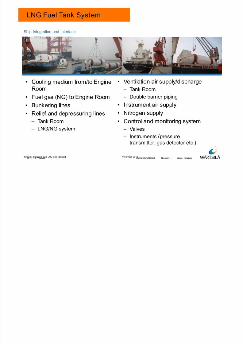
LNG Fuel Tank System
• Cooling medium from/to Engine
Room
• Fuel gas (NG) to Engine Room
• Bunkering lines
• Relief and depressuring lines
– Tank Room
– LNG/NG system
• Ventilation air supply/discharge
– Tank Room
– Double barrier piping
• Instrument air supply
• Nitrogen supply
• Control and monitoring system
– Valves
– Instruments (pressure
transmitter, gas detector etc.)
Ship Integration and Interface
Kystnær transport med LNG som drivstoff November 2010
7/23/2019 8 Lng Fuel Supply System_tcm142-520675
http://slidepdf.com/reader/full/8-lng-fuel-supply-systemtcm142-520675 14/50
Finalised-DBAB982956Doc.ID: Revision: Status:50/ © Wärtsilä
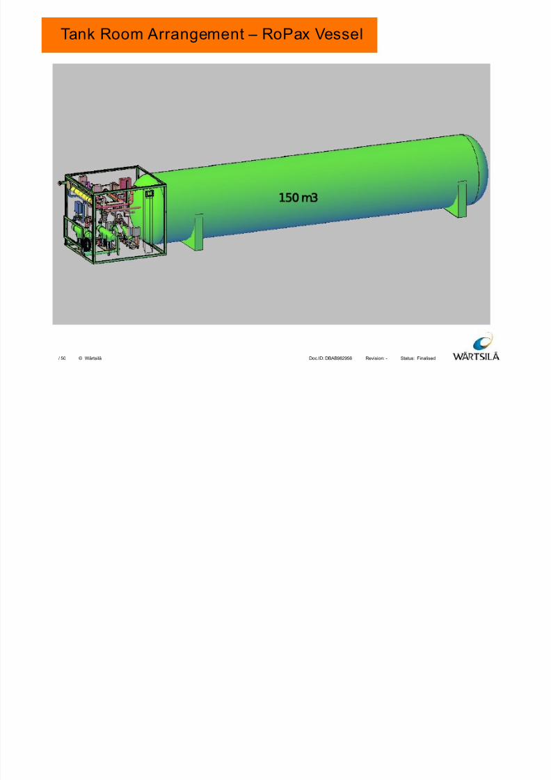
Tank Room Arrangement – RoPax Vessel
15 m3
7/23/2019 8 Lng Fuel Supply System_tcm142-520675
http://slidepdf.com/reader/full/8-lng-fuel-supply-systemtcm142-520675 15/50
Finalised-DBAB982956Doc.ID: Revision: Status:50/ © Wärtsilä
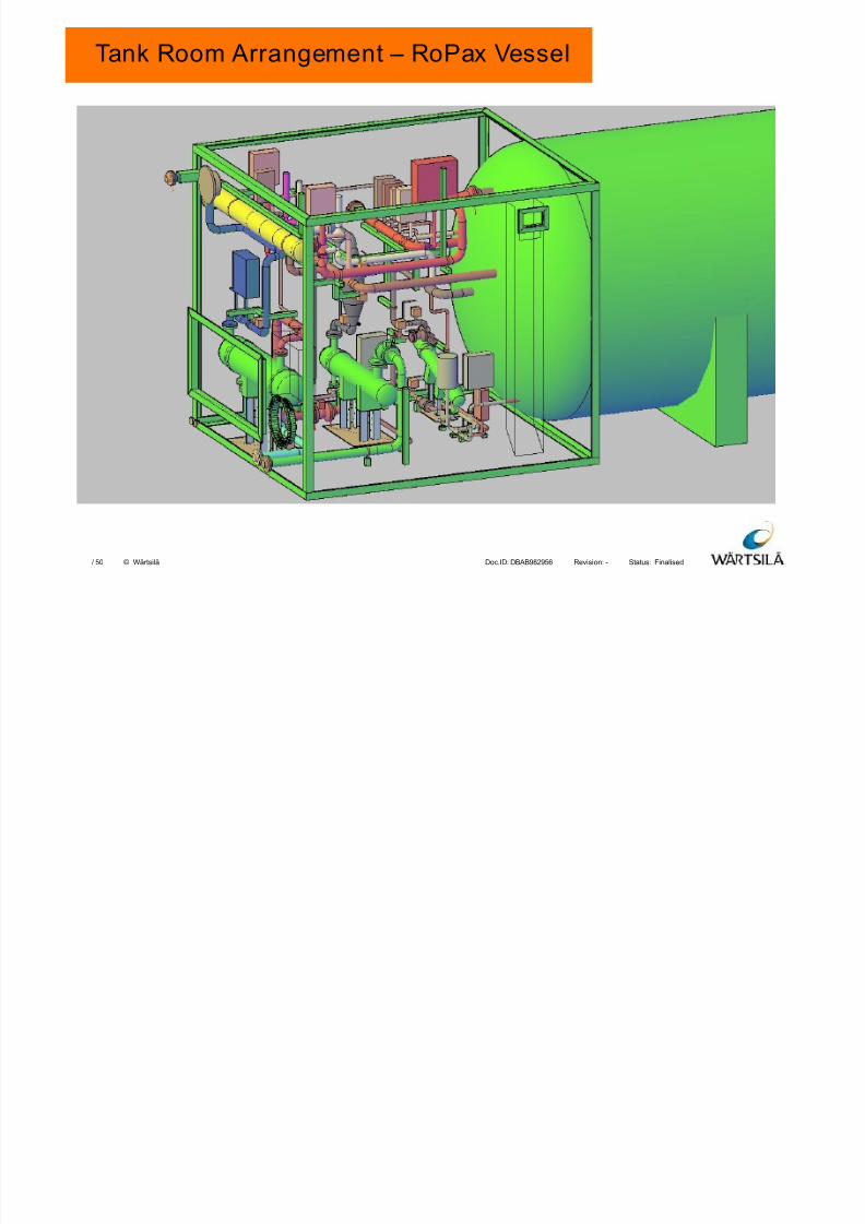
Tank Room Arrangement – RoPax Vessel
7/23/2019 8 Lng Fuel Supply System_tcm142-520675
http://slidepdf.com/reader/full/8-lng-fuel-supply-systemtcm142-520675 16/50
Finalised-DBAB982956Doc.ID: Revision: Status:50/ © Wärtsilä
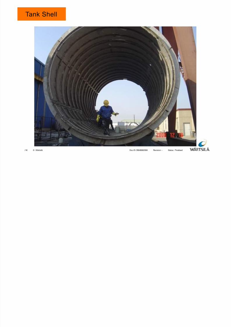
Tank Shell
7/23/2019 8 Lng Fuel Supply System_tcm142-520675
http://slidepdf.com/reader/full/8-lng-fuel-supply-systemtcm142-520675 17/50
Finalised-DBAB982956Doc.ID: Revision: Status:50/ © Wärtsilä
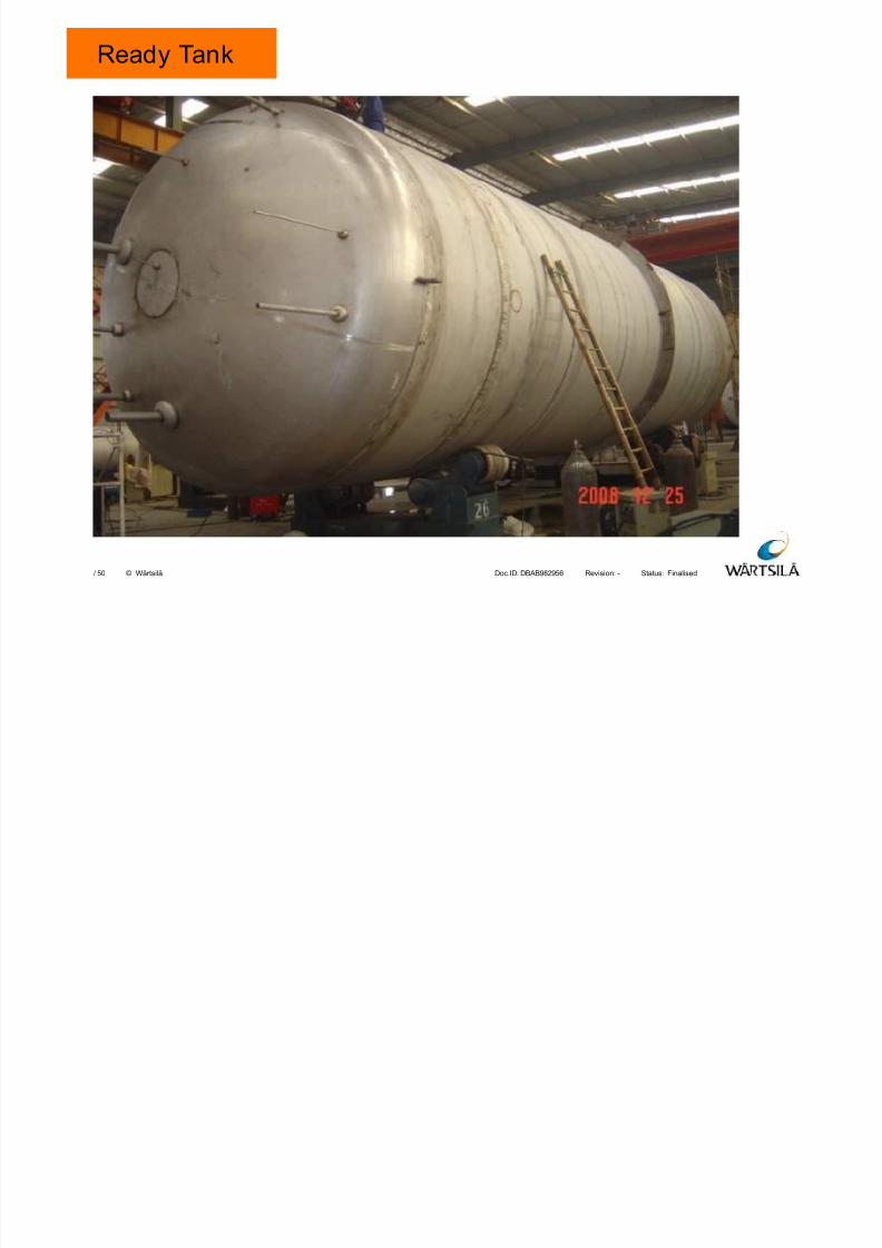
Ready Tank
7/23/2019 8 Lng Fuel Supply System_tcm142-520675
http://slidepdf.com/reader/full/8-lng-fuel-supply-systemtcm142-520675 18/50
Finalised-DBAB982956Doc.ID: Revision: Status:50/ © Wärtsilä
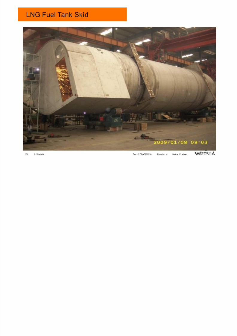
LNG Fuel Tank Skid
7/23/2019 8 Lng Fuel Supply System_tcm142-520675
http://slidepdf.com/reader/full/8-lng-fuel-supply-systemtcm142-520675 19/50
Finalised-DBAB982956Doc.ID: Revision: Status:50/ © Wärtsilä
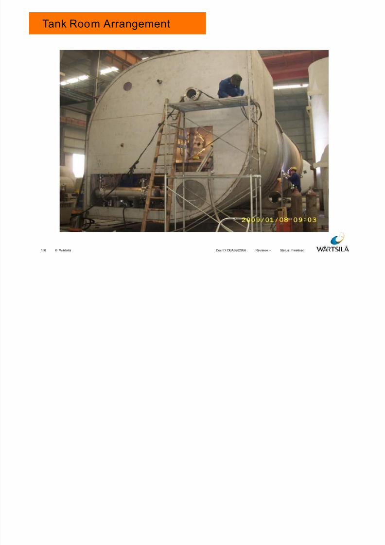
Tank Room Arrangement
7/23/2019 8 Lng Fuel Supply System_tcm142-520675
http://slidepdf.com/reader/full/8-lng-fuel-supply-systemtcm142-520675 20/50
Finalised-DBAB982956Doc.ID: Revision: Status:50/ © Wärtsilä
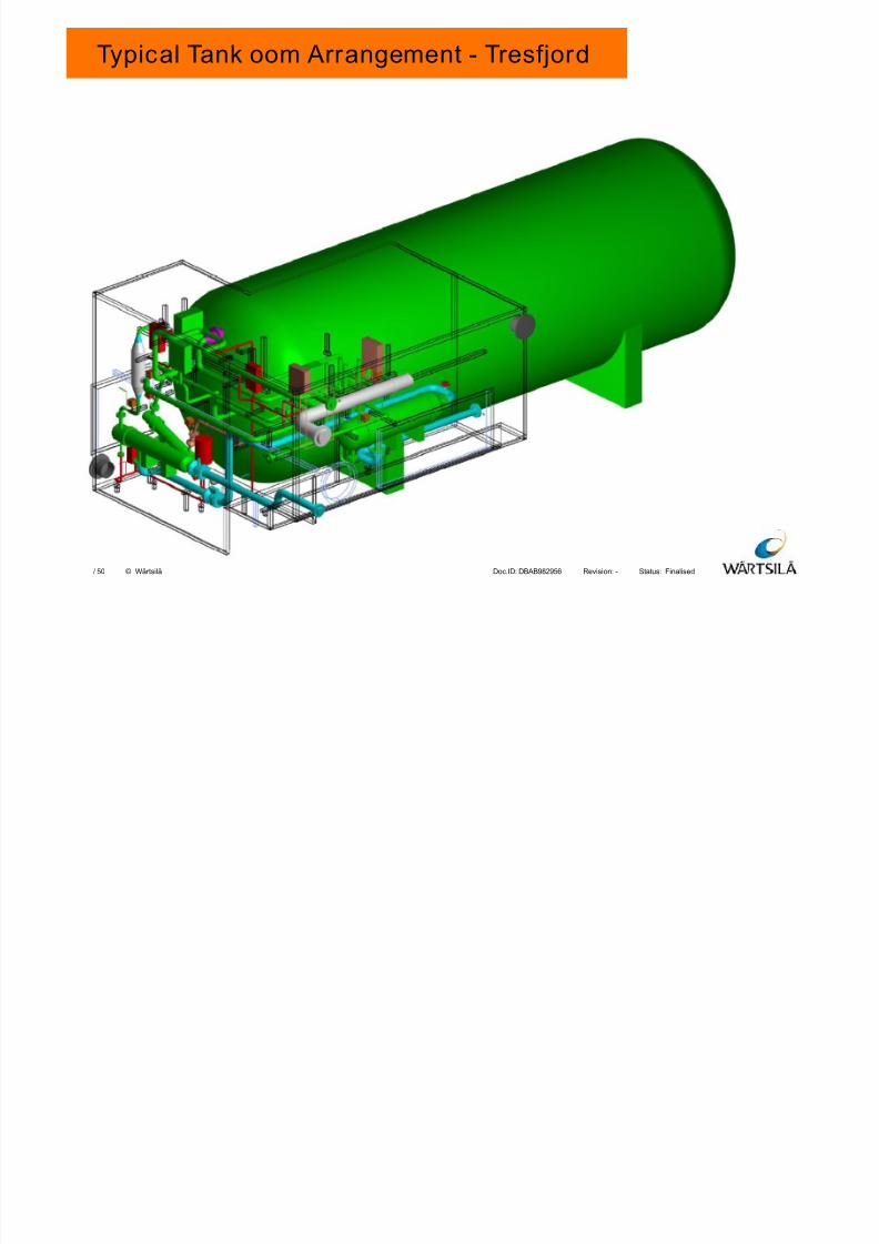
Typical Tank oom Arrangement - Tresfjord
7/23/2019 8 Lng Fuel Supply System_tcm142-520675
http://slidepdf.com/reader/full/8-lng-fuel-supply-systemtcm142-520675 21/50
Finalised-DBAB982956Doc.ID: Revision: Status:50/ © Wärtsilä
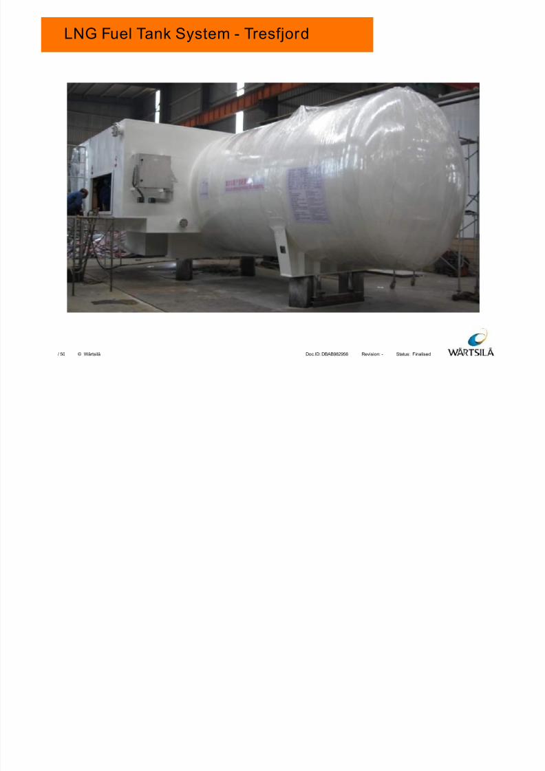
LNG Fuel Tank System - Tresfjord
7/23/2019 8 Lng Fuel Supply System_tcm142-520675
http://slidepdf.com/reader/full/8-lng-fuel-supply-systemtcm142-520675 22/50
Finalised-DBAB982956Doc.ID: Revision: Status:50/ © Wärtsilä
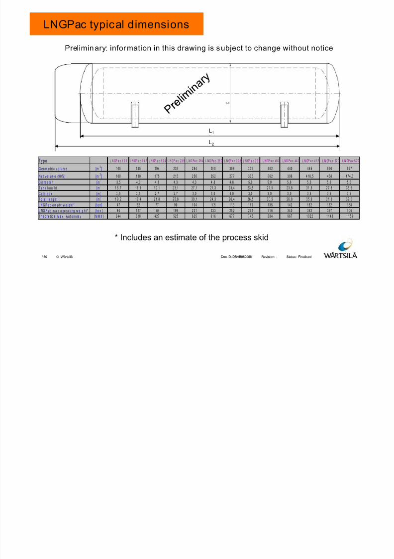
LNGPac typical dimensions
L1
L2
Preliminary: information in this drawing is subject to change without notice
T y p e L N GP a c 1 0 5 L N GP a c 1 4 5 L N GP a c 1 9 4 L NGP a c 23 9 L NG Pa c 28 4 L NG Pa c 28 0 L N GP a c 3 0 8 L N GP a c 3 3 9 L NGP a c 40 2 L NG Pa c 44 0 L N GP a c 4 6 5 L N GP a c 52 0 L N GP a c 5 2 7
G e o m e t r i c v o l u m e [m3] 105 1 45 19 4 239 2 84 28 0 30 8 3 3 9 40 2 4 40 46 5 520 5 27
N e t v o l u m e (9 0 %) [m3] 1 00 1 30 1 7 5 2 15 2 56 25 2 27 7 3 0 5 36 2 3 96 41 8 ,5 468 4 74 ,3
D i a m e t e r [ m ] 3, 5 4 , 0 4 ,3 4 ,3 4 ,3 4 ,8 4 ,8 5 ,0 5 ,0 5 , 6 5 ,0 5 , 6 5 , 0
T a n k l e n g h t [ m ] 1 6 , 7 1 6 ,9 1 9 ,1 2 3 ,1 27 ,1 21 ,3 2 3 ,4 23 ,5 2 7 , 5 23 ,8 3 1 , 5 2 7 , 8 3 5 , 5
C o l d b o x [ m ] 2, 5 2 , 5 2 ,7 2 ,7 3 ,0 3 ,0 3 ,0 3 , 0 3 ,0 3 , 0 3 ,5 3 , 5 3 , 5
T o t a l l e n g h t [ m ] 1 9 , 2 1 9 ,4 2 1 ,8 2 5 ,8 30 ,1 24 ,3 2 6 , 4 26 , 5 3 0 , 5 26 ,8 3 5 , 0 3 1 , 3 3 9 , 0
L N G P a c e m p t y w e i g h t * [ t o n ] 47 62 77 9 0 1 04 10 5 11 3 1 1 9 13 5 1 42 15 2 162 1 68
L NG P ac m a x o pe ra ti ng w e i g h t* [ t o n ] 9 4 1 27 1 6 4 1 98 2 31 23 3 25 2 2 7 1 31 6 3 4 0 36 2 397 4 06
T h e o r e t ic a l M a x . A u t o n o m y [ M W h ] 2 44 3 18 4 2 7 5 25 6 25 61 6 67 7 7 4 5 88 4 9 6 7 1 02 2 11 4 3 11 59
* Includes an estimate of the process skid
7/23/2019 8 Lng Fuel Supply System_tcm142-520675
http://slidepdf.com/reader/full/8-lng-fuel-supply-systemtcm142-520675 23/50
Finalised-DBAB982956Doc.ID: Revision: Status:50/ © Wärtsilä
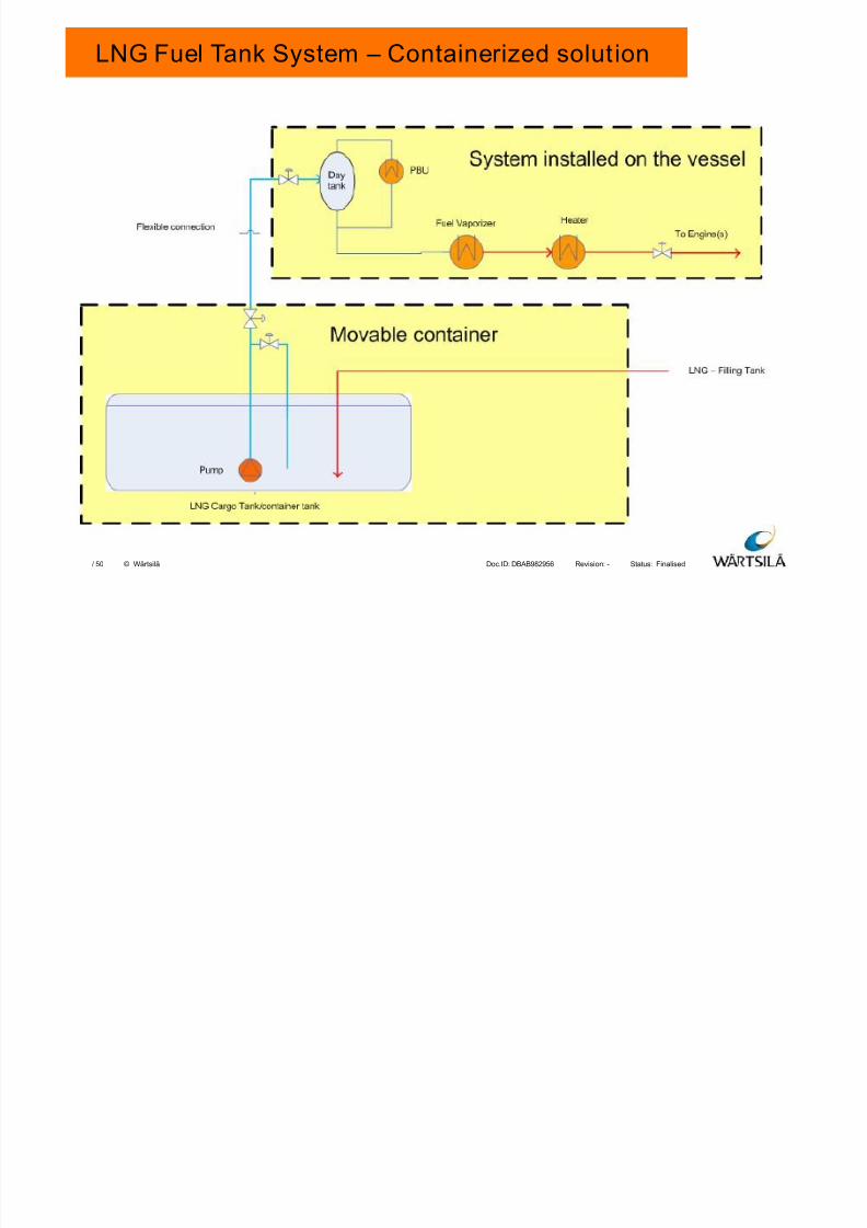
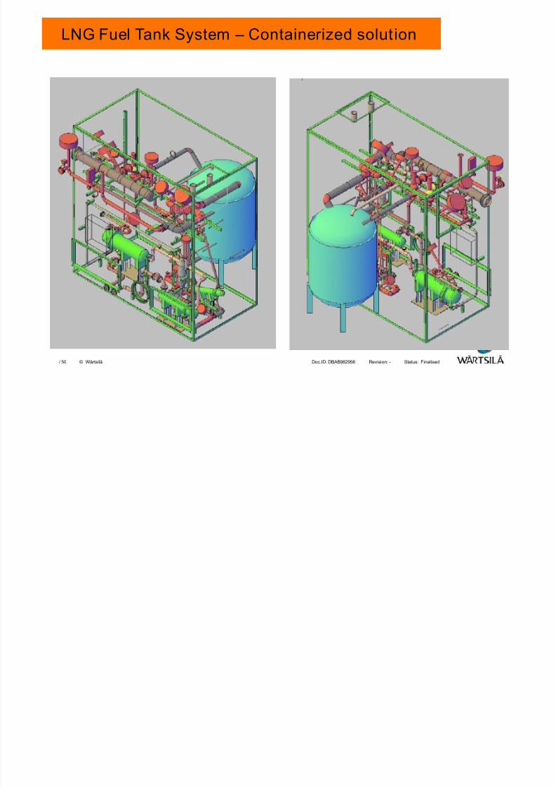
LNG Fuel Tank System – Containerized solution
7/23/2019 8 Lng Fuel Supply System_tcm142-520675
http://slidepdf.com/reader/full/8-lng-fuel-supply-systemtcm142-520675 24/50
Finalised-DBAB982956Doc.ID: Revision: Status:50/ © Wärtsilä
LNG Fuel Tank System – Containerized solution

7/23/2019 8 Lng Fuel Supply System_tcm142-520675
http://slidepdf.com/reader/full/8-lng-fuel-supply-systemtcm142-520675 25/50
Finalised-DBAB982956Doc.ID: Revision: Status:50/ © Wärtsilä
AGENDA
1. LNG FUEL TANK
2. LOW PRESSURE (LP) SYSTEM
3. HIGH PRESSURE (HP) SYSTEM
4. LP AND HP COMBINED SYSTEM
5. CHALLENGES
6. WHY WARTSILA HAMWORTHY
25
7/23/2019 8 Lng Fuel Supply System_tcm142-520675
http://slidepdf.com/reader/full/8-lng-fuel-supply-systemtcm142-520675 26/50
Finalised-DBAB982956Doc.ID: Revision: Status:50/ © WärtsiläSeptember 2010Master Template Page 26
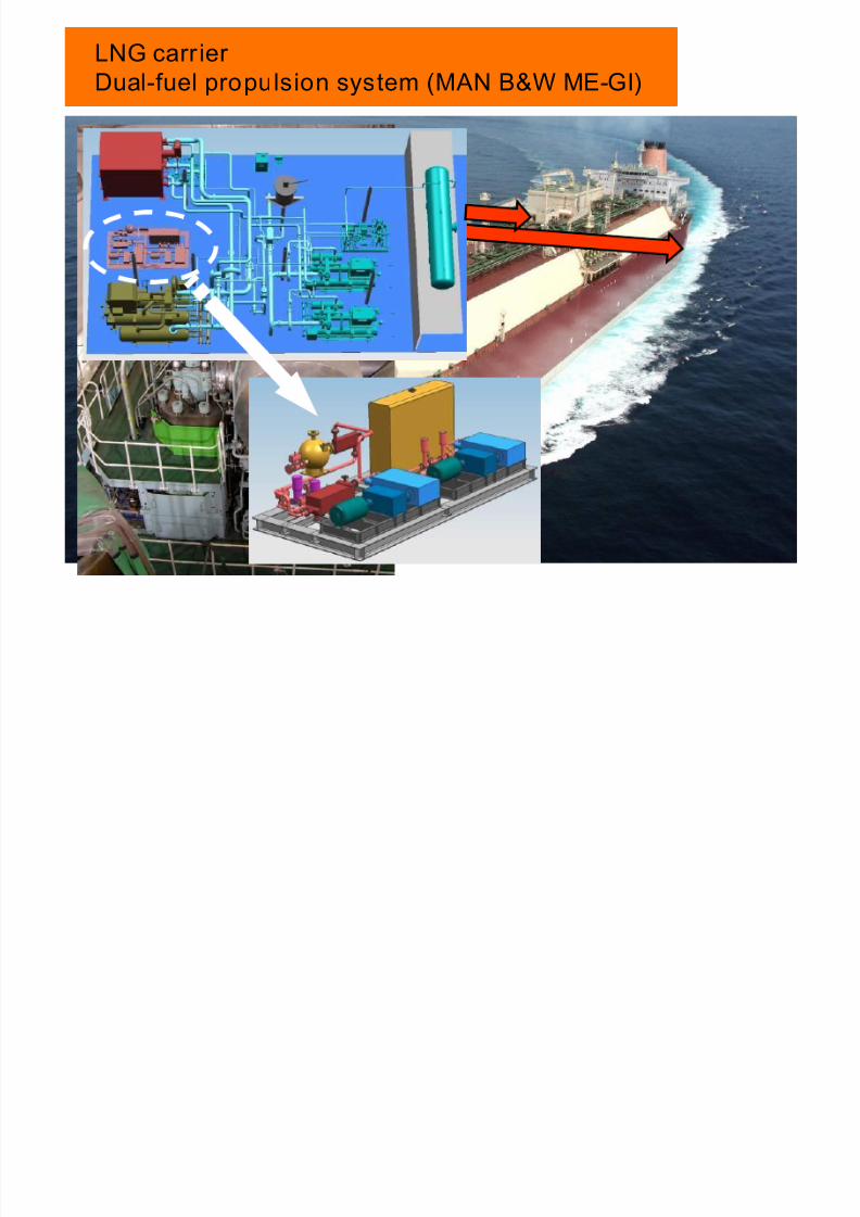
LNG carrier Dual-fuel propulsion system (MAN B&W ME-GI)
7/23/2019 8 Lng Fuel Supply System_tcm142-520675
http://slidepdf.com/reader/full/8-lng-fuel-supply-systemtcm142-520675 27/50
Finalised-DBAB982956Doc.ID: Revision: Status:50/ © Wärtsilä
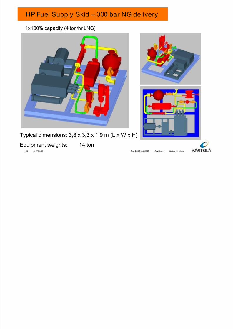
Typical dimensions: 3,8 x 3,3 x 1,9 m (L x W x H)
Equipment weights: 14 ton
1x100% capacity (4 ton/hr LNG)
HP Fuel Supply Skid – 300 bar NG delivery
7/23/2019 8 Lng Fuel Supply System_tcm142-520675
http://slidepdf.com/reader/full/8-lng-fuel-supply-systemtcm142-520675 28/50
Finalised-DBAB982956Doc.ID: Revision: Status:50/ © Wärtsilä
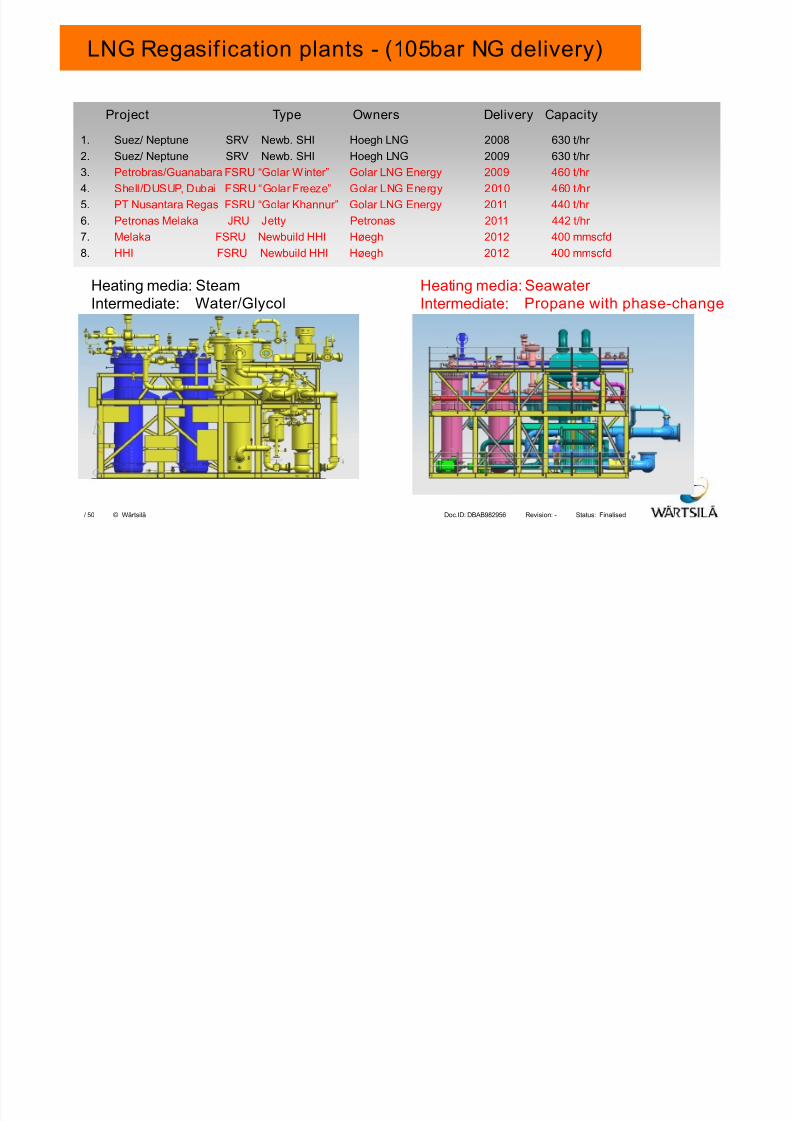
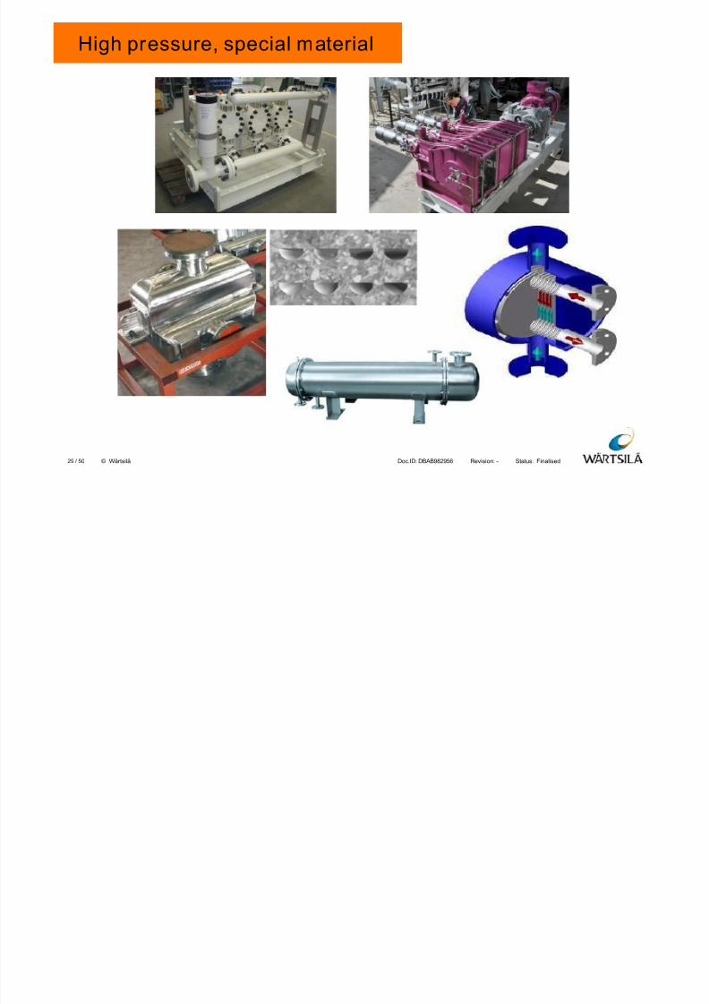
LNG Regasif ication plants - (105bar NG delivery)
Heating media: SteamIntermediate: Water/Glycol
Heating media: Seawater Intermediate: Propane with phase-change
Project Type Owners Delivery Capacity
1. Suez/ Neptune SRV Newb. SHI Hoegh LNG 2008 630 t/hr 2. Suez/ Neptune SRV Newb. SHI Hoegh LNG 2009 630 t/hr
3. Petrobras/Guanabara FSRU “Golar Winter” Golar LNG Energy 2009 460 t/hr
4. Shell/DUSUP, Dubai FSRU “Golar Freeze” Golar LNG Energy 2010 460 t/hr
5. PT Nusantara Regas FSRU “Golar Khannur” Golar LNG Energy 2011 440 t/hr
6. Petronas Melaka JRU Jetty Petronas 2011 442 t/hr
7. Melaka FSRU Newbuild HHI Høegh 2012 400 mmscfd
8. HHI FSRU Newbuild HHI Høegh 2012 400 mmscfd
7/23/2019 8 Lng Fuel Supply System_tcm142-520675
http://slidepdf.com/reader/full/8-lng-fuel-supply-systemtcm142-520675 29/50
Finalised-DBAB982956Doc.ID: Revision: Status:50/ © Wärtsilä
High pressure, special material
29
7/23/2019 8 Lng Fuel Supply System_tcm142-520675
http://slidepdf.com/reader/full/8-lng-fuel-supply-systemtcm142-520675 30/50
Finalised-DBAB982956Doc.ID: Revision: Status:50/ © Wärtsilä
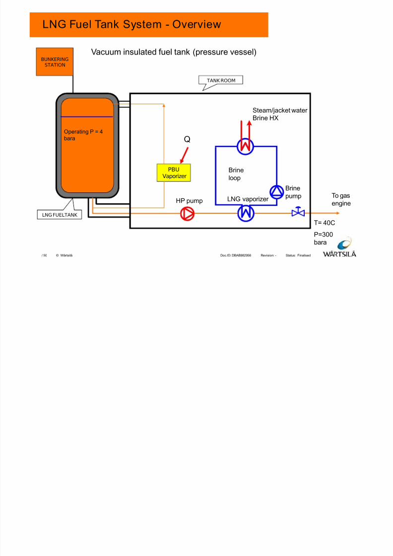
LNG Fuel Tank System - Overview
BUNKERINGSTATION
Brine
loop
Brine
pump
Steam/jacket water
Brine HX
LNG vaporizer HP pumpTo gas
engine
Vacuum insulated fuel tank (pressure vessel)
PBUVaporizer
Operating P = 4
bara
T= 40C
P=300
bara
LNG FUELTANK
TANK ROOM
Q

7/23/2019 8 Lng Fuel Supply System_tcm142-520675
http://slidepdf.com/reader/full/8-lng-fuel-supply-systemtcm142-520675 31/50
Finalised-DBAB982956Doc.ID: Revision: Status:50/ © Wärtsilä
AGENDA
1. LNG FUEL TANK
2. LOW PRESSURE (LP) SYSTEM
3. HIGH PRESSURE (HP) SYSTEM
4. LP AND HP COMBINED SYSTEM
5. CHALLENGES
6. WHY WARTSILA HAMWORTHY
31
7/23/2019 8 Lng Fuel Supply System_tcm142-520675
http://slidepdf.com/reader/full/8-lng-fuel-supply-systemtcm142-520675 32/50
Finalised-DBAB982956Doc.ID: Revision: Status:50/ © Wärtsilä
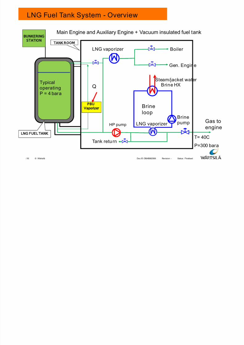
LNG Fuel Tank System - Overview
BUNKERING
STATION
Brineloop
Brinepump
Steam/jacket water
Brine HX
LNG vaporizer HP pumpGas to
engine
Main Engine and Auxiliary Engine + Vacuum insulated fuel tank
PBU
Vaporizer
Typical
operatingP = 4 bara
T= 40C
P=300 bara
LNG FUEL TANK
TANK ROOM
Q
Boiler
Gen. Engine
LNG vaporizer
Tank return
7/23/2019 8 Lng Fuel Supply System_tcm142-520675
http://slidepdf.com/reader/full/8-lng-fuel-supply-systemtcm142-520675 33/50
Finalised-DBAB982956Doc.ID: Revision: Status:50/ © Wärtsilä
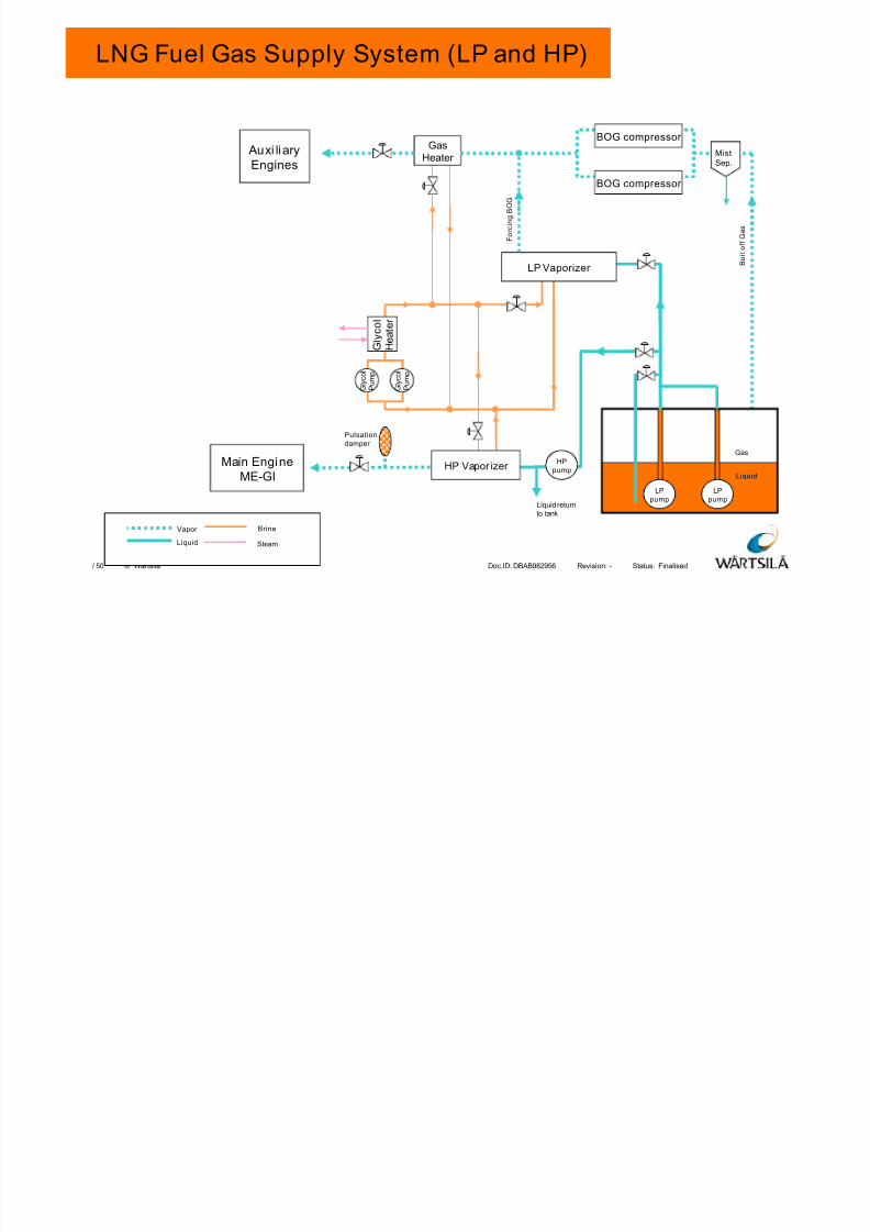
B o i l o f f G a s
HPpump
Auxi liaryEngines
BOG compressor
Liquid
Gas
F o r c i n g B O G
G l y c o l
H e a t e r
G l y c o l
P u m p
LPpump
LPpump
Gas
Heater
Pulsationdamper
Liquid return
to tank
BOG compressor
LP Vaporizer
HP Vapor izer
G l y c o l
P u m p
MistSep.
Main EngineME-GI
Vapor
Liquid
Brine
Steam
LNG Fuel Gas Supply System (LP and HP)

7/23/2019 8 Lng Fuel Supply System_tcm142-520675
http://slidepdf.com/reader/full/8-lng-fuel-supply-systemtcm142-520675 34/50
Finalised-DBAB982956Doc.ID: Revision: Status:50/ © Wärtsilä
AGENDA
1. LNG FUEL TANK
2. LOW PRESSURE (LP) SYSTEM
3. HIGH PRESSURE (HP) SYSTEM
4. LP AND HP COMBINED SYSTEM
5. CHALLENGES
6. WHY WARTSILA HAMWORTHY
34
7/23/2019 8 Lng Fuel Supply System_tcm142-520675
http://slidepdf.com/reader/full/8-lng-fuel-supply-systemtcm142-520675 35/50
Finalised-DBAB982956Doc.ID: Revision: Status:50/ © Wärtsilä
Standards and Requirements to be Followed:
• 1970’s : Gas Tank & Code Development Era• IGC - ”International Code for the Construction and Equipment of Ships
Carrying Liquefied Gases in Bulk”:
• “IMO Interim Guidelines on Safety for Natural Gas Fuelled EngineInstallations in Ships”
• Local requirement/Flag state requirement
• Class requirement/class guidelines• DNV Rules Part 6 Chapter 13 Gas Fuelled Engine Installations
7/23/2019 8 Lng Fuel Supply System_tcm142-520675
http://slidepdf.com/reader/full/8-lng-fuel-supply-systemtcm142-520675 36/50
Finalised-DBAB982956Doc.ID: Revision: Status:50/ © Wärtsilä
Challenges
Main challange is to optimise and reduce the energy consumption on
vessels:
• Utilise Boil-off gas (energy in the gas and cold duty)
• Utilise the available cold duty in the LNG as fuel:
• Air-condition
• Refrigeration
• Cooling inlet air to engine
• Cooling jacket water (normally done with sea water)
• Cool or liquefy cargo with LNG (VOC, gas etc)
Important to look at the complete energy
balance of the vessel!
Utilizing available energy – Optimize the energy consumption
7/23/2019 8 Lng Fuel Supply System_tcm142-520675
http://slidepdf.com/reader/full/8-lng-fuel-supply-systemtcm142-520675 37/50
Finalised-DBAB982956Doc.ID: Revision: Status:50/ © Wärtsilä
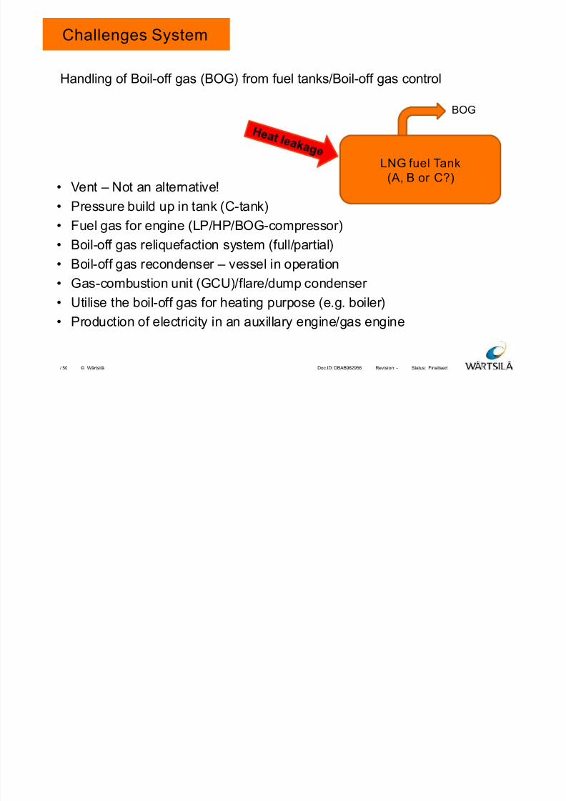
Challenges System
• Vent – Not an alternative!
• Pressure build up in tank (C-tank)
• Fuel gas for engine (LP/HP/BOG-compressor)
• Boil-off gas reliquefaction system (full/partial)
• Boil-off gas recondenser – vessel in operation
• Gas-combustion unit (GCU)/flare/dump condenser
• Utilise the boil-off gas for heating purpose (e.g. boiler)
• Production of electricity in an auxillary engine/gas engine
Handling of Boil-off gas (BOG) from fuel tanks/Boil-off gas control
LNG fuel Tank(A, B or C?)
BOG
7/23/2019 8 Lng Fuel Supply System_tcm142-520675
http://slidepdf.com/reader/full/8-lng-fuel-supply-systemtcm142-520675 38/50
Finalised-DBAB982956Doc.ID: Revision: Status:50/ © Wärtsilä
AGENDA
1. LNG FUEL TANK
2. LOW PRESSURE (LP) SYSTEM
3. HIGH PRESSURE (HP) SYSTEM
4. LP AND HP COMBINED SYSTEM
5. CHALLENGES
6. WHY WARTSILA HAMWORTHY
38
7/23/2019 8 Lng Fuel Supply System_tcm142-520675
http://slidepdf.com/reader/full/8-lng-fuel-supply-systemtcm142-520675 39/50
Finalised-DBAB982956Doc.ID: Revision: Status:50/ © Wärtsilä
HAMWORTHY IS NOW PART OF THE WÄRTSILÄ FAMILY
39
7/23/2019 8 Lng Fuel Supply System_tcm142-520675
http://slidepdf.com/reader/full/8-lng-fuel-supply-systemtcm142-520675 40/50
Finalised-DBAB982956Doc.ID: Revision: Status:50/ © Wärtsilä
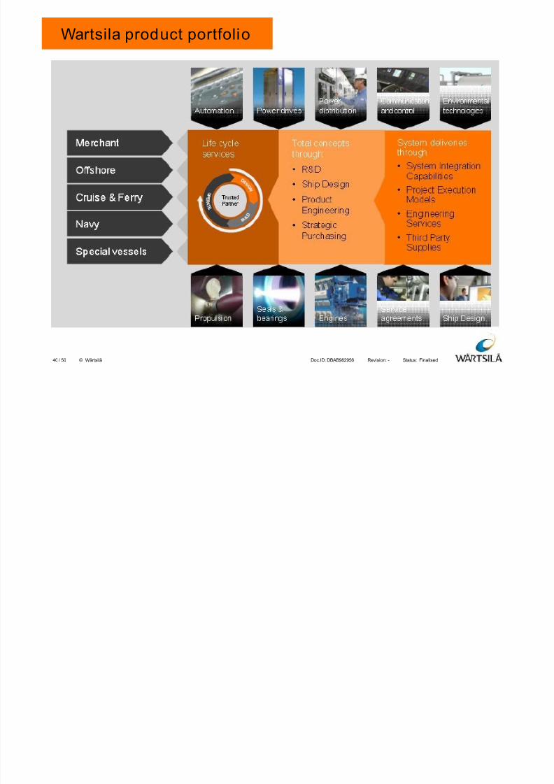
Wartsila product portfolio
40
7/23/2019 8 Lng Fuel Supply System_tcm142-520675
http://slidepdf.com/reader/full/8-lng-fuel-supply-systemtcm142-520675 41/50
Finalised-DBAB982956Doc.ID: Revision: Status:50/ © Wärtsilä
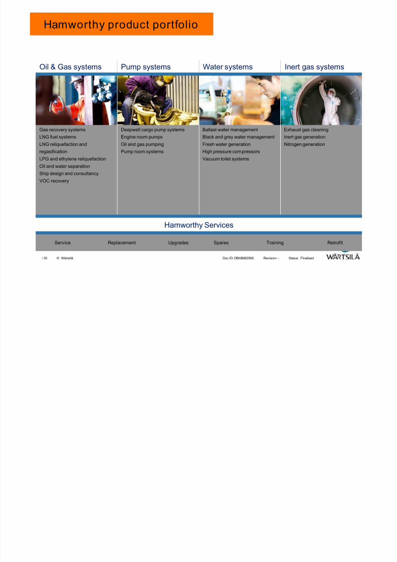
Pump systemsOil & Gas systems Water systems Inert gas systems
Hamworthy Services
Service Replacement Upgrades Spares Training Retrofit
Gas recovery systems
LNG fuel systems
LNG reliquefaction and
regasification
LPG and ethylene reliquefaction
Oil and water separation
Ship design and consultancy
VOC recovery
Exhaust gas cleaning
Inert gas generation
Nitrogen generation
Ballast water management
Black and grey water management
Fresh water generation
High pressure compressors
Vacuum toilet systems
Deepwell cargo pump systems
Engine room pumps
Oil and gas pumping
Pump room systems
Hamworthy product portfolio
7/23/2019 8 Lng Fuel Supply System_tcm142-520675
http://slidepdf.com/reader/full/8-lng-fuel-supply-systemtcm142-520675 42/50
Finalised-DBAB982956Doc.ID: Revision: Status:50/ © Wärtsilä
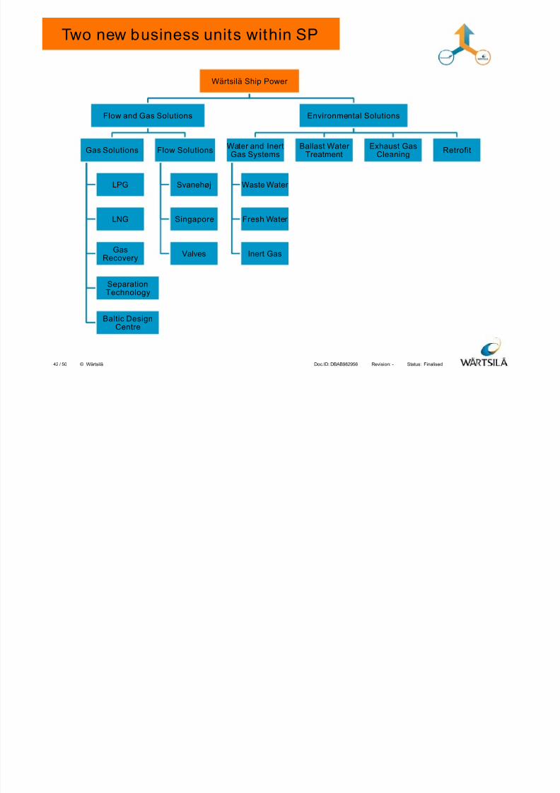
Two new business units within SP
Wärtsilä Ship Power
Flow and Gas Solutions
Gas Solutions
LPG
LNG
GasRecovery
SeparationTechnology
Baltic DesignCentre
Flow Solutions
Svanehøj
Singapore
Valves
Environmental Solutions
Water and InertGas Systems
Waste Water
Fresh Water
Inert Gas
Ballast WaterTreatment
Exhaust GasCleaning Retrofit
42
7/23/2019 8 Lng Fuel Supply System_tcm142-520675
http://slidepdf.com/reader/full/8-lng-fuel-supply-systemtcm142-520675 43/50
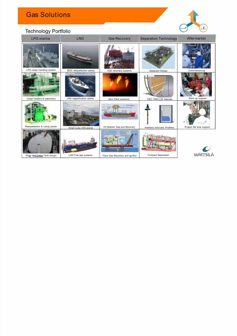
Gas Solut ions
LPG marine LNG Gas Recovery Separation Technology
LPG cargo handling system
Reliquefaction & coling plants
Cargo heaters & vaporizers
VOC recovery systems
Small scale LNG plants
LNG regasification plants
BOG reliquefaction plants
Aftermarket
Commissioning
Start–up support
Project life time support
Zero Flare solutions
Technology Portfolio
Ship- and Cargo Tank design
HC Blanket Gas and Recovery
LNG Fuel gas systems Flare Gas Recovery and ignition Compact Separation
VIEC /VIEC-LW Internals
Interface level and Profilers
Separator Design
43 © Wä rtsi l ä
7/23/2019 8 Lng Fuel Supply System_tcm142-520675
http://slidepdf.com/reader/full/8-lng-fuel-supply-systemtcm142-520675 44/50
Finalised-DBAB982956Doc.ID: Revision: Status:50/ © Wärtsilä
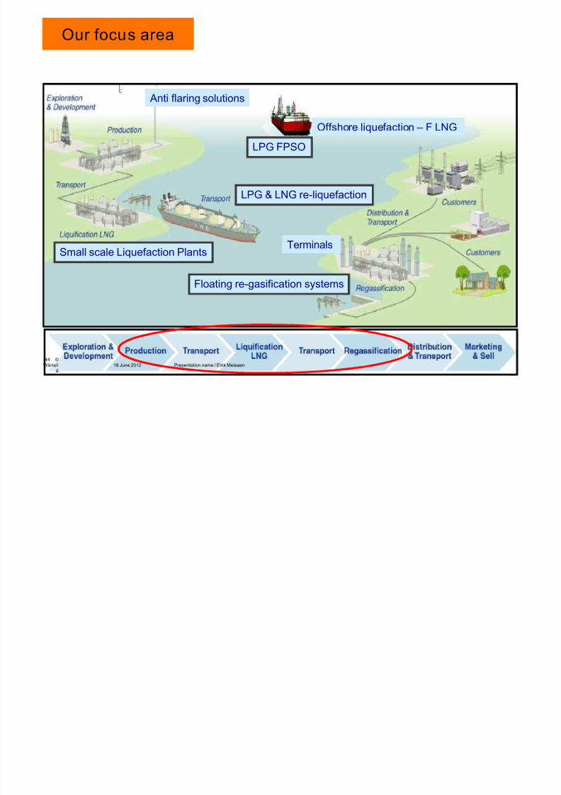
Our focus area
Small scale Liquefaction Plants
Anti flaring solutions
Floating re-gasification systems
Terminals
LPG & LNG re-liquefaction
Offshore liquefaction – F LNG
LPG FPSO
44 ©Wärtsil
äPresentation name / Eirik Melaaen18 June 2012
7/23/2019 8 Lng Fuel Supply System_tcm142-520675
http://slidepdf.com/reader/full/8-lng-fuel-supply-systemtcm142-520675 45/50
7/23/2019 8 Lng Fuel Supply System_tcm142-520675
http://slidepdf.com/reader/full/8-lng-fuel-supply-systemtcm142-520675 46/50
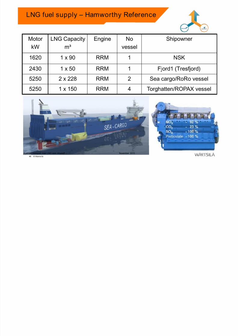
Motor
kW
LNG Capacity
m³
Engine No
vessel
Shipowner
1620 1 x 90 RRM 1 NSK
2430 1 x 50 RRM 1 Fjord1 (Tresfjord)
5250 2 x 228 RRM 2 Sea cargo/RoRo vessel
5250 1 x 150 RRM 4 Torghatten/ROPAX vessel
LNG fuel supply – Hamworthy Reference
Kystnær transport med LNG som drivstoff November 2010
46 © Wä rtsi l ä
7/23/2019 8 Lng Fuel Supply System_tcm142-520675
http://slidepdf.com/reader/full/8-lng-fuel-supply-systemtcm142-520675 47/50
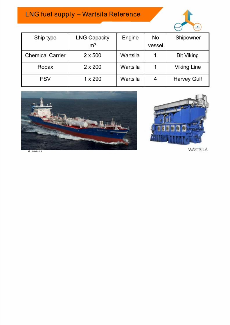
Ship type LNG Capacity
m³
Engine No
vessel
Shipowner
Chemical Carrier 2 x 500 Wartsila 1 Bit Viking
Ropax 2 x 200 Wartsila 1 Viking Line
PSV 1 x 290 Wartsila 4 Harvey Gulf
LNG fuel supply – Wartsila Reference
Kystnær transport med LNG som drivstoff November 2010
47 © Wä rtsi l ä
7/23/2019 8 Lng Fuel Supply System_tcm142-520675
http://slidepdf.com/reader/full/8-lng-fuel-supply-systemtcm142-520675 48/50
Finalised-DBAB982956Doc.ID: Revision: Status:50/ © Wärtsilä
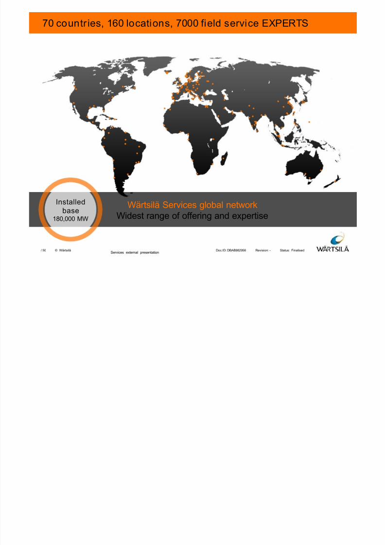
70 countr ies, 160 locations, 7000 field service EXPERTS
Wärtsilä Services global networkWidest range of offering and expertise
Installedbase180,000 MW
Services external presentation
7/23/2019 8 Lng Fuel Supply System_tcm142-520675
http://slidepdf.com/reader/full/8-lng-fuel-supply-systemtcm142-520675 49/50
Finalised-DBAB982956Doc.ID: Revision: Status:50/ © Wärtsilä
Wartsila Hamworthy Ltd.
49
7/23/2019 8 Lng Fuel Supply System_tcm142-520675
http://slidepdf.com/reader/full/8-lng-fuel-supply-systemtcm142-520675 50/50
Finalised-DBAB982956Doc.ID: Revision: Status:50/ © Wärtsilä50
THANK YOU FOR YOUR ATTENTION!
Barry Yang ( )
Sales Director, China
Flow & Gas / Environmental Solutions
Ship Power, Wärtsilä China Ltd
Mob: 13801724719
Email: [email protected]