8. CommTroubleshooting 1
47
Slide 1 © Max Zornada (2011) Trouble Shooting and Trouble Shooting and Problem Solving Problem Solving
description
commissioning
Transcript of 8. CommTroubleshooting 1
Slide 1© Max Zornada (2011)
Trouble Shooting and Problem SolvingTrouble Shooting and Problem Solving

Slide 2© Max Zornada (2011)
Murphy’s LawMurphy’s Law
If some thing can go wrong, it will go wrong!
During start-up there are lots of things that can go wrong, and they all do!
Hopefully not all the once.

Slide 3© Max Zornada (2011)
Case StudyCase Study
Ethylene Glycol PlantEthylene Glycol Plant

Slide 4© Max Zornada (2011)
The Ethylene Glycol Plant SchematicThe Ethylene Glycol Plant Schematic

Slide 5© Max Zornada (2011)
The Current SituationThe Current Situation An Ethylene Glycol Plant has been commissioned and was now An Ethylene Glycol Plant has been commissioned and was now
operating successfully and producing product.operating successfully and producing product. The plant had been started up and shutdown on several occasions as The plant had been started up and shutdown on several occasions as
part of its performance testing schedule.part of its performance testing schedule. The normal start up procedure consisted of placing a batch of glycerol The normal start up procedure consisted of placing a batch of glycerol
in the reactor. This was circulated through the heat exchanger where it in the reactor. This was circulated through the heat exchanger where it was heated.was heated.
When the glycerol temperature reached 115º C the addition of ethylene When the glycerol temperature reached 115º C the addition of ethylene oxide was commenced by starting pump J1.oxide was commenced by starting pump J1.
The reaction was exothermic, so once the batch reactor reached 115º C The reaction was exothermic, so once the batch reactor reached 115º C and the ethylene oxide feed commenced, the heat exchanger was used and the ethylene oxide feed commenced, the heat exchanger was used as a cooler to keep the temperature within the specified range and to as a cooler to keep the temperature within the specified range and to control the reaction dynamics.control the reaction dynamics.

Slide 6© Max Zornada (2011)
Safety InterlocksSafety Interlocks Addition of ethylene oxide could not commence Addition of ethylene oxide could not commence
unless the circulation pump (J2) was running;unless the circulation pump (J2) was running; The glycerol or batch temperature (read by the The glycerol or batch temperature (read by the
temperature indicator at TZA) was above 115 º C temperature indicator at TZA) was above 115 º C (otherwise the ethylene oxide would not react);(otherwise the ethylene oxide would not react);
The temperature (TZA) was below 125 º C The temperature (TZA) was below 125 º C (Otherwise the reaction would be too fast.(Otherwise the reaction would be too fast.
Slide 7© Max Zornada (2011)
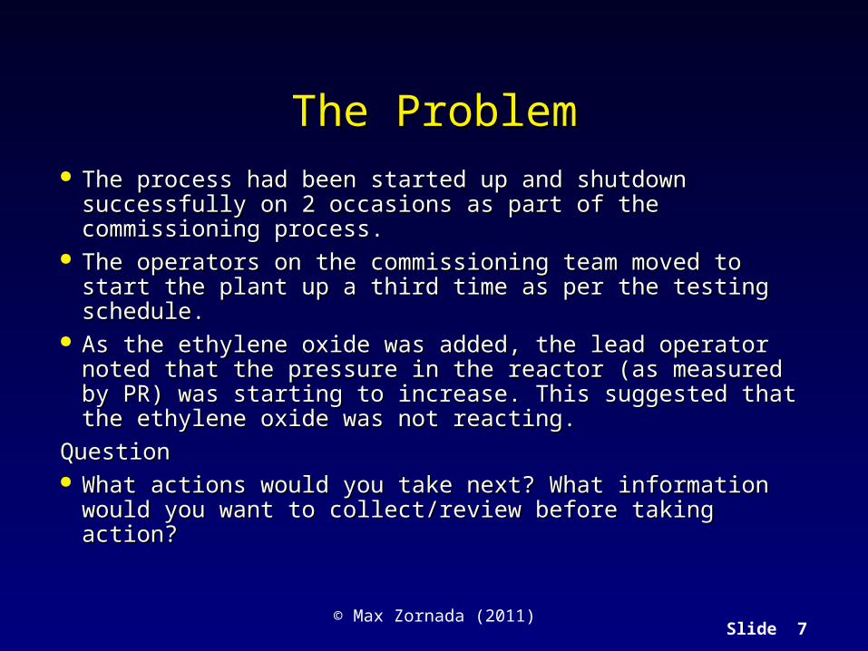
The ProblemThe Problem The process had been started up and shutdown successfully on The process had been started up and shutdown successfully on
2 occasions as part of the commissioning process.2 occasions as part of the commissioning process. The operators on the commissioning team moved to start the The operators on the commissioning team moved to start the
plant up a third time as per the testing schedule. plant up a third time as per the testing schedule. As the ethylene oxide was added, the lead operator noted that As the ethylene oxide was added, the lead operator noted that
the pressure in the reactor (as measured by PR) was starting to the pressure in the reactor (as measured by PR) was starting to increase. This suggested that the ethylene oxide was not increase. This suggested that the ethylene oxide was not reacting.reacting.
QuestionQuestion What actions would you take next? What information would What actions would you take next? What information would
you want to collect/review before taking action?you want to collect/review before taking action?

Slide 8© Max Zornada (2011)
What the operator did nextWhat the operator did next
The operator decided that perhaps the temperature point was The operator decided that perhaps the temperature point was reading low, or perhaps a bit more heat was required to get the reading low, or perhaps a bit more heat was required to get the reaction rate up, so he adjusted the trip setting (TZA High) and reaction rate up, so he adjusted the trip setting (TZA High) and allowed the indicated temperature to rise to 200 º C.allowed the indicated temperature to rise to 200 º C.
Still the pressure did not fall.Still the pressure did not fall. Next he checked the valve at the bottom of the reactor and Next he checked the valve at the bottom of the reactor and
found it shut.found it shut.
QuestionQuestion What actions would you take next? What information would What actions would you take next? What information would
you want to collect/review before taking action?you want to collect/review before taking action?

Slide 9© Max Zornada (2011)
What happened!What happened!
The operator opened the valve! Three tonnes of unreacted ethylene oxide, together with
glycerol passed through the heater and catalyser and a violent uncontrolled reaction occurred. The reactor burst and the escaping gases exploded.
Question What measures would you take to ensure an incident like
this cannot happen again?

Slide 10© Max Zornada (2011)
Why did it happenWhy did it happen The explosion was due to an operator forgetting to The explosion was due to an operator forgetting to
open a valve;open a valve; Superficially, we could say Superficially, we could say human error!human error! However, it was one of those mistakes that even However, it was one of those mistakes that even
well trained, motivated and capable people make;well trained, motivated and capable people make; As is the case with almost all accidents and failures As is the case with almost all accidents and failures
attributed to human error, there is usually an attributed to human error, there is usually an underlying cause;underlying cause;
Opening the valve was probably an instinctive action.Opening the valve was probably an instinctive action.

Slide 11© Max Zornada (2011)
Further Analysis - 1Further Analysis - 1 Failure to assess situation and “jumping to conclusions”Failure to assess situation and “jumping to conclusions”
High pressure in reactor was an early warning sign;High pressure in reactor was an early warning sign; The operator “jumped to a conclusion” about what was causing this and The operator “jumped to a conclusion” about what was causing this and
therefore failed to look for addition data to diagnose the problem. Eg. Checking therefore failed to look for addition data to diagnose the problem. Eg. Checking other temperature points and flow reading.other temperature points and flow reading.
Explosion was due to the failure to directly measure the property we need to know;Explosion was due to the failure to directly measure the property we need to know; Temperature point was not measuring the temperature in the reactor, it was Temperature point was not measuring the temperature in the reactor, it was
measuring the temperature near the pump - these might be the same during measuring the temperature near the pump - these might be the same during normal operations but during start up they can be different (as this example normal operations but during start up they can be different (as this example shows).shows).
Slide 12© Max Zornada (2011)
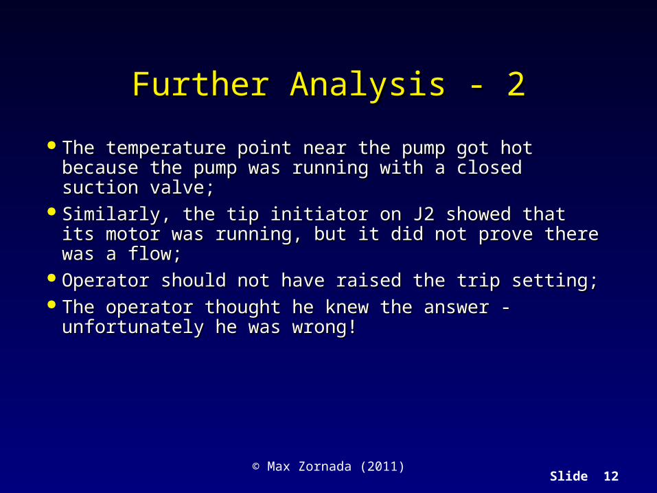
Further Analysis - 2Further Analysis - 2
The temperature point near the pump got hot because The temperature point near the pump got hot because the pump was running with a closed suction valve;the pump was running with a closed suction valve;
Similarly, the tip initiator on J2 showed that its motor Similarly, the tip initiator on J2 showed that its motor was running, but it did not prove there was a flow;was running, but it did not prove there was a flow;
Operator should not have raised the trip setting;Operator should not have raised the trip setting; The operator thought he knew the answer - The operator thought he knew the answer -
unfortunately he was wrong!unfortunately he was wrong!
Slide 13© Max Zornada (2011)
What should we do?What should we do?
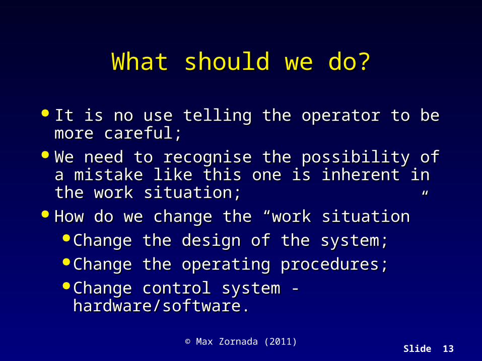
It is no use telling the operator to be more careful;It is no use telling the operator to be more careful; We need to recognise the possibility of a mistake We need to recognise the possibility of a mistake
like this one is inherent in the work situation;like this one is inherent in the work situation; How do we change the “work situation”How do we change the “work situation”
Change the design of the system;Change the design of the system; Change the operating procedures;Change the operating procedures; Change control system - hardware/software.Change control system - hardware/software.

Slide 14© Max Zornada (2011)
Some general principlesSome general principles
Measure the property we wish to know directly;Measure the property we wish to know directly; Measuring the temperature at the pump was not a measure Measuring the temperature at the pump was not a measure
of the temperature in the vessel;of the temperature in the vessel; Pump energised and running as an interlock, did not mean Pump energised and running as an interlock, did not mean
there was flow;there was flow; Operators should not be able to tamper with process standards Operators should not be able to tamper with process standards
- e.g. changing trip settings;- e.g. changing trip settings; A high pressure trip should have been installed on the reactor;A high pressure trip should have been installed on the reactor; Process should have been stopped once the close valves was Process should have been stopped once the close valves was
found and re-start from “scratch”.found and re-start from “scratch”.

Slide 15© Max Zornada (2011)
Trouble Shooting and Problem SolvingTrouble Shooting and Problem Solving

Slide 16© Max Zornada (2011)
What is Trouble ShootingWhat is Trouble Shooting
Application of Problem Solving methods to the Application of Problem Solving methods to the diagnosis and improvement after deviations occur diagnosis and improvement after deviations occur in a system.in a system.
We do this in our every-day lives all the timeWe do this in our every-day lives all the time

Slide 17© Max Zornada (2011)
Problem Solving ProcessProblem Solving ProcessIdentify the problem
Brain storm possible solutions
Identify most likely cause
Collect data
Identify preferred solution
Brainstorm possible causes
Implement
Check that it worked
Slide 18© Max Zornada (2011)
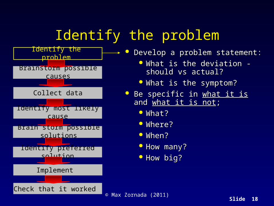
Identify the problemIdentify the problemIdentify the problem
Brain storm possible solutions
Identify most likely cause
Collect data
Identify preferred solution
Brainstorm possible causes
Implement
Check that it worked
Develop a problem statement:Develop a problem statement: What is the deviation - should vs What is the deviation - should vs
actual?actual? What is the symptom?What is the symptom?
Be specific in Be specific in what it iswhat it is and and what it is notwhat it is not;; What?What? Where?Where? When?When? How many?How many? How big?How big?

Slide 19© Max Zornada (2011)
Problems as deviationsProblems as deviations
What should be happening
What is happening
What is happening= What should be happeningNo Problem!
What is happening different to What should be happening= Problem!

Slide 20© Max Zornada (2011)
Three types of problemsThree types of problems
Ongoing an recentOngoing an recent
Has always been thereHas always been there
One-off eventOne-off event

Slide 21© Max Zornada (2011)
Brainstorm Possible CausesBrainstorm Possible CausesIdentify the problem
Brain storm possible solutions
Identify most likely cause
Collect data
Identify preferred solution
Implement
Check that it worked
Brainstorm possible causes
What could be causing the What could be causing the problem or symptom?problem or symptom?
What is different?What is different? What has changed?What has changed? How could each change have How could each change have
caused the problem?caused the problem?

Slide 22© Max Zornada (2011)
Collect DataCollect DataIdentify the problem
Brain storm possible solutions
Identify most likely cause
Collect data
Identify preferred solution
Implement
Check that it worked
Brainstorm possible causes
Collect data about the potential Collect data about the potential causes to see which can be causes to see which can be substantiated by facts and substantiated by facts and observations.observations.
Type text
Slide 23© Max Zornada (2011)
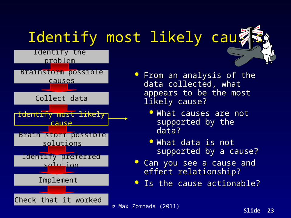
Identify most likely causesIdentify most likely causesIdentify the problem
Brain storm possible solutions
Identify most likely cause
Collect data
Identify preferred solution
Implement
Check that it worked
Brainstorm possible causes From an analysis of the data From an analysis of the data collected, what appears to be the collected, what appears to be the most likely cause?most likely cause?
What causes are not supported What causes are not supported by the data?by the data?
What data is not supported by a What data is not supported by a cause?cause?
Can you see a cause and effect Can you see a cause and effect relationship?relationship?
Is the cause actionable?Is the cause actionable?

Slide 24© Max Zornada (2011)
Brainstorm possible solutionsBrainstorm possible solutionsIdentify the problem
Brain storm possible solutions
Identify most likely cause
Collect data
Identify preferred solution
Implement
Check that it worked
Brainstorm possible causes
What actions will remove or What actions will remove or address the cause?address the cause?

Slide 25© Max Zornada (2011)
Types of potential solutionsTypes of potential solutions
Eliminate cause;Eliminate cause; Neutralise the effect or impact of the cause;Neutralise the effect or impact of the cause; Remove the need for the thing that is giving us the Remove the need for the thing that is giving us the
problem.problem.

Slide 26© Max Zornada (2011)
Identify preferred solutionIdentify preferred solutionIdentify the problem
Brain storm possible solutions
Identify most likely cause
Collect data
Identify preferred solution
Implement
Check that it worked
Brainstorm possible causes
Assess potential actions on Assess potential actions on basis of:basis of:
Ease of implementation;Ease of implementation; Cost?Cost? Degree to which they solve Degree to which they solve
the problem;the problem; Sustainability;Sustainability; Any other relevant criteria.Any other relevant criteria.
Select the preferred solution Select the preferred solution and implement;and implement;

Slide 27© Max Zornada (2011)
ImplementImplementIdentify the problem
Brain storm possible solutions
Identify most likely cause
Collect data
Identify preferred solution
Implement
Check that it worked
Brainstorm possible causes
Select the preferred solution Select the preferred solution and implement;and implement;

Slide 28© Max Zornada (2011)
Check that it workedCheck that it workedIdentify the problem
Brain storm possible solutions
Identify most likely cause
Collect data
Identify preferred solution
Implement
Check that it worked
Brainstorm possible causes
Check to see that it worked;Check to see that it worked; If not:If not:
Re-assess solutions;Re-assess solutions; Re-assess possible causes;Re-assess possible causes; Re-assess problem definition.Re-assess problem definition.

Slide 29© Max Zornada (2011)
Why solutions don’t workWhy solutions don’t work
We misunderstood the problem;We misunderstood the problem; We understood the problem but identified the We understood the problem but identified the
wrong cause;wrong cause; We understood the problems, identified the correct We understood the problems, identified the correct
cause, picked the wrong solution.cause, picked the wrong solution.
Slide 30© Max Zornada (2011)
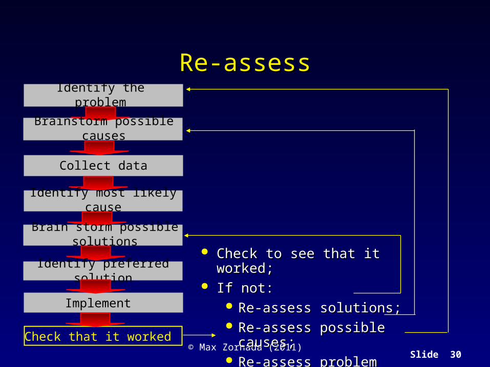
Re-assessRe-assessIdentify the problem
Brain storm possible solutions
Identify most likely cause
Collect data
Identify preferred solution
Implement
Check that it worked
Brainstorm possible causes
Check to see that it worked;Check to see that it worked; If not:If not:
Re-assess solutions;Re-assess solutions; Re-assess possible causes;Re-assess possible causes; Re-assess problem definition.Re-assess problem definition.
Slide 31© Max Zornada (2011)
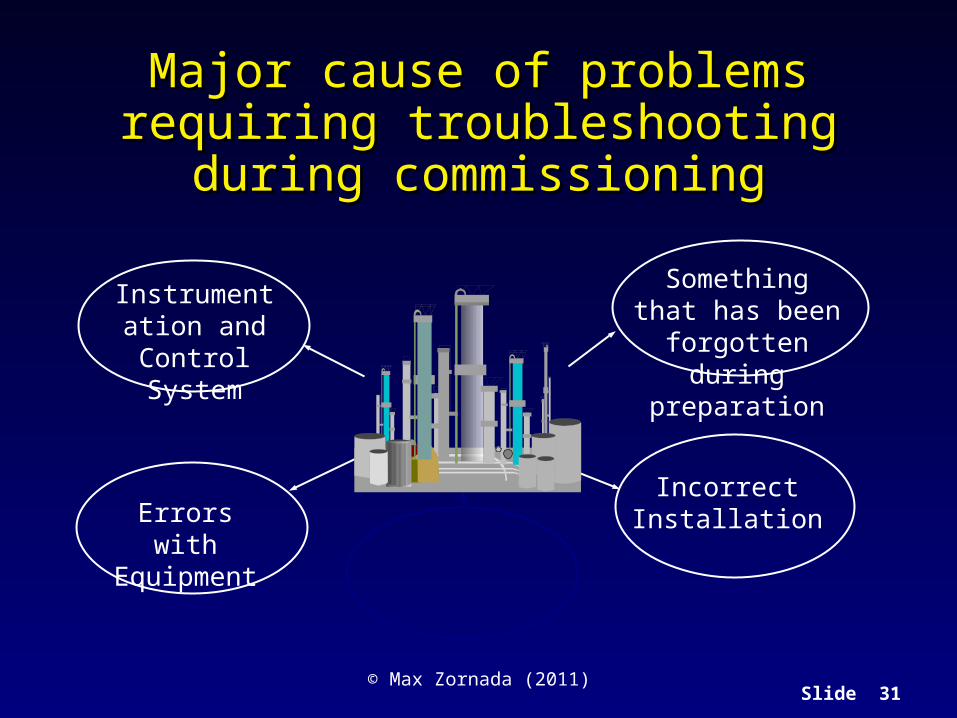
Major cause of problems requiring Major cause of problems requiring troubleshooting during commissioningtroubleshooting during commissioning
Instrumentation and Control
System
Something that has been forgotten
during preparation
Incorrect InstallationErrors with
Equipment

Slide 32© Max Zornada (2011)
Some examplesSome examplesInstrumentation and Control System Something that has been
forgotten during preparation
Incorrect InstallationErrors with Equipment Incorrectly specified equipment Incapable equipment Wrong equipment for the job Poor materials selection Underdesign – capacity/strength
Dirt and debris blocking flow lines, instrument lines and instruments
Valve left closed when should be open Blind left in place
Instrument(s) not working/broken Incorrect calibration Incorrect control logic Software bugs Not switched on
Equipment installed incorrectly; Equipment environment does not meet
specification – eg. Straight run lengths Valves, instruments etc installed back-
to-front

Slide 33© Max Zornada (2011)
Startup trouble shooting guidelines ...Startup trouble shooting guidelines ...
1.1. Compare data with those taken during safe-fluid and solvent Compare data with those taken during safe-fluid and solvent tests.tests.
2. Make small inexpensive changes in operating conditions and 2. Make small inexpensive changes in operating conditions and take more data.take more data.
3. Log more data, getting complete recordings of temperatures, 3. Log more data, getting complete recordings of temperatures, pressures, flows and conditions of utilities in the troubled pressures, flows and conditions of utilities in the troubled area.area.
4. Review design calculations.4. Review design calculations.
5.5. Inspect mechanical features of equipment.Inspect mechanical features of equipment.
6. Regularly calculate material balances, adding 6. Regularly calculate material balances, adding instrumentation and taking special samples.instrumentation and taking special samples.

Slide 34© Max Zornada (2011)
Startup trouble shooting guidelines ...Startup trouble shooting guidelines ...
7.7. Investigate the unsteady-state analysis and design of plant.Investigate the unsteady-state analysis and design of plant.
8.8. Make minor equipment changes and take more data.Make minor equipment changes and take more data.
9. Increase data recording.9. Increase data recording.
10. Provide additional automation to smoothen operations 10. Provide additional automation to smoothen operations and release operators from routine tasks.and release operators from routine tasks.
11. Furnish the operators with amenities that will make it 11. Furnish the operators with amenities that will make it easier for them to pay closer attention to operational easier for them to pay closer attention to operational details.details.
12. Automate or record, or both, the vent and purge streams.12. Automate or record, or both, the vent and purge streams.

Slide 35© Max Zornada (2011)
Trouble Shooting Instrumentation and Trouble Shooting Instrumentation and Control ProblemsControl Problems

Slide 36© Max Zornada (2011)
Case Study: Steam Boiler CommissioningCase Study: Steam Boiler Commissioning
As part of an expansion program of a Natural Gas Processing plant, As part of an expansion program of a Natural Gas Processing plant, and additional high pressure steam boiler is being added to the boiler and additional high pressure steam boiler is being added to the boiler house;house;
There are already 7 steam boilers in operation;There are already 7 steam boilers in operation; The new boiler is number 8 in the series and is of similar design to The new boiler is number 8 in the series and is of similar design to
the previous 7. A ninth boiler is currently under construction;the previous 7. A ninth boiler is currently under construction; The plant is located in a remote location, and the high pressure steam The plant is located in a remote location, and the high pressure steam
is used to generate power using steam turbine driven generators;is used to generate power using steam turbine driven generators; The low pressure steam from the steam turbine exhaust is used as The low pressure steam from the steam turbine exhaust is used as
process steam for heating in heat exchangers and in the regeneration process steam for heating in heat exchangers and in the regeneration towers that regenerate the gas sweetening solution.towers that regenerate the gas sweetening solution.

Slide 37© Max Zornada (2011)
Case Study: Steam Boiler CommissioningCase Study: Steam Boiler Commissioning
A general view of the boilerhouse area, showing some of the boilers.
A boiler unitNo. 8 Boiler
No. 9 BoilerUnder
construction
Slide 38© Max Zornada (2011)
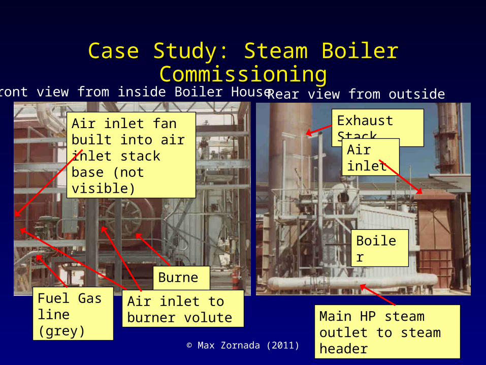
Case Study: Steam Boiler CommissioningCase Study: Steam Boiler Commissioning
Main HP steam outlet to steam header
Burner
Exhaust Stack
Air inlet
Boiler
Front view from inside Boiler House Rear view from outside
Fuel Gas line (grey)
Air inlet fan built into air inlet stack base (not visible)
Air inlet to burner volute

Slide 39© Max Zornada (2011)
Case Study: Steam Boiler CommissioningCase Study: Steam Boiler Commissioning The boiler featured a local panel mounter display and The boiler featured a local panel mounter display and
controller that could be calibrated to display on a linear controller that could be calibrated to display on a linear or log linear scale. The linear calibration had been the or log linear scale. The linear calibration had been the norm.norm.
The boiler was rated at a normal operating capacity of The boiler was rated at a normal operating capacity of 41 tonnes of superheated steam per hour under 41 tonnes of superheated steam per hour under continuous operating conditions, with a maximum continuous operating conditions, with a maximum capacity of 45 tonnes per hour.capacity of 45 tonnes per hour.
During commissioning, the boiler was tested by During commissioning, the boiler was tested by ramping up to 45 tonnes to hour and holding and then ramping up to 45 tonnes to hour and holding and then backing off to 41 tonnes per hour.backing off to 41 tonnes per hour.

Slide 40© Max Zornada (2011)
Case Study: Steam Boiler CommissioningCase Study: Steam Boiler CommissioningProblemProblem
Air inlet stack
Fuel gas in
Fan
Air inlet to burner
Exhaust stack
CO2 Measurement of exhaust used to monitor combustion efficiency
Local panel mounted controller and display
Indicates 41 tonnes/hour
Main steam header
Main control room DCS displays
Boiler steam production show 41 tonnes/hour
Main steam header shows increase in steam of 37 tonnes/hour
Slide 41© Max Zornada (2011)
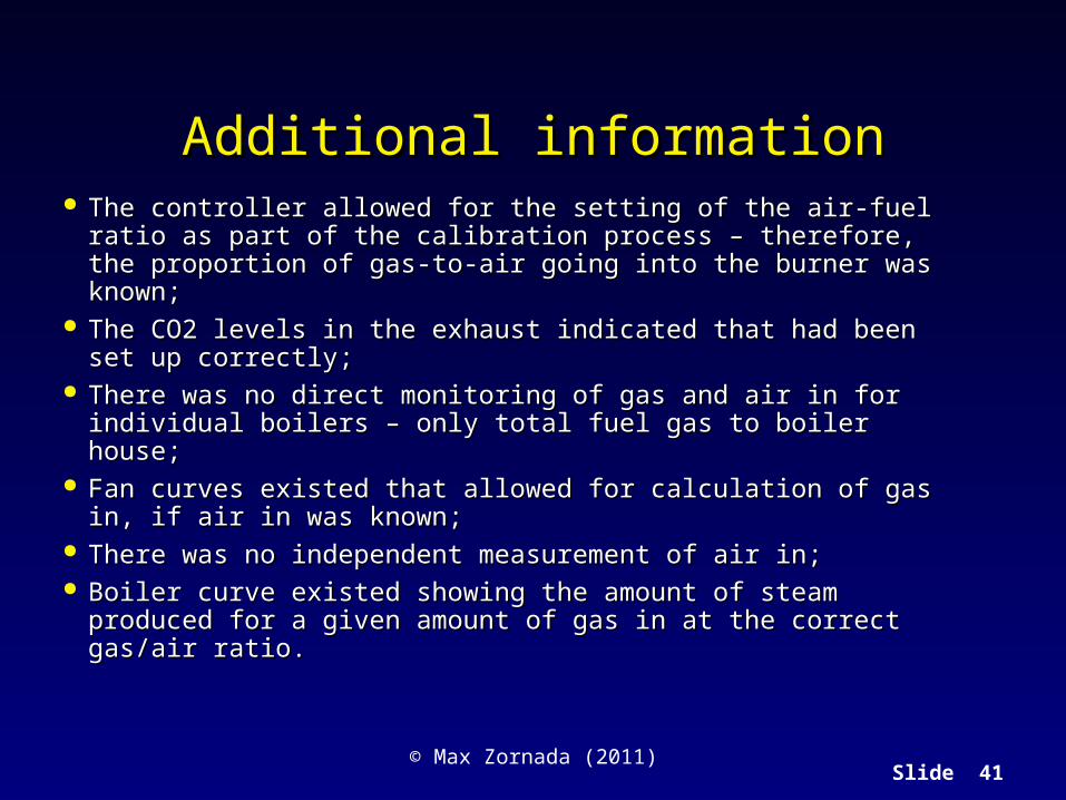
Additional informationAdditional information The controller allowed for the setting of the air-fuel ratio as part The controller allowed for the setting of the air-fuel ratio as part
of the calibration process – therefore, the proportion of gas-to-air of the calibration process – therefore, the proportion of gas-to-air going into the burner was known;going into the burner was known;
The CO2 levels in the exhaust indicated that had been set up The CO2 levels in the exhaust indicated that had been set up correctly;correctly;
There was no direct monitoring of gas and air in for individual There was no direct monitoring of gas and air in for individual boilers – only total fuel gas to boiler house;boilers – only total fuel gas to boiler house;
Fan curves existed that allowed for calculation of gas in, if air in Fan curves existed that allowed for calculation of gas in, if air in was known;was known;
There was no independent measurement of air in;There was no independent measurement of air in; Boiler curve existed showing the amount of steam produced for a Boiler curve existed showing the amount of steam produced for a
given amount of gas in at the correct gas/air ratio.given amount of gas in at the correct gas/air ratio.
Slide 42© Max Zornada (2011)
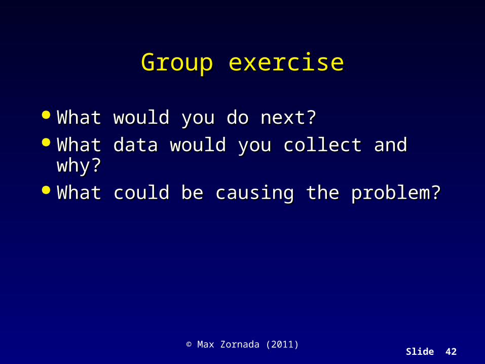
Group exerciseGroup exercise
What would you do next?What would you do next? What data would you collect and why?What data would you collect and why? What could be causing the problem?What could be causing the problem?

Slide 43© Max Zornada (2011)
Major causes of measurement errors and Major causes of measurement errors and failuresfailures
Sensing lines that are plugged or that contain liquid when they should Sensing lines that are plugged or that contain liquid when they should be dry;be dry;
Sensing elements with excessive coating, fouling or abrasion;Sensing elements with excessive coating, fouling or abrasion; Excessive bubbles or solids in process fluid;Excessive bubbles or solids in process fluid; Sensing elements with cracks, deformations or holes;Sensing elements with cracks, deformations or holes; Low Reynolds Number for process fluid;Low Reynolds Number for process fluid; Gaskets or O rings that leak;Gaskets or O rings that leak; Inappropriate materials of construction;Inappropriate materials of construction; Sensing, pneumatic or electronic components affected by process or Sensing, pneumatic or electronic components affected by process or
ambient temperature;ambient temperature; Moisture on the sensing element or signal connections;Moisture on the sensing element or signal connections; Electrical interference;Electrical interference;
Slide 44© Max Zornada (2011)
Major causes of measurement errors and Major causes of measurement errors and failuresfailures
Electrical interference;Electrical interference; High connection or wiring resistance;High connection or wiring resistance; Non-representative sensing point;Non-representative sensing point; Inadequate straight pipe runs for flow sensor;Inadequate straight pipe runs for flow sensor; Nozzle that are plugged or fouled;Nozzle that are plugged or fouled; Feedback linkages that shift or contain excessive play/untight Feedback linkages that shift or contain excessive play/untight
connections;connections; Incorrect calibrations.Incorrect calibrations.

Slide 45© Max Zornada (2011)
Causes of Control Valve Errors and Causes of Control Valve Errors and FailuresFailures
High trim-seating friction for sliding stem valves and high ball, plug or High trim-seating friction for sliding stem valves and high ball, plug or disc friction for rotary valves;disc friction for rotary valves;
High packing friction;High packing friction; Loose shaft connections on rotary valves;Loose shaft connections on rotary valves; Long shafts or linkages with loose connections on rotary valves;Long shafts or linkages with loose connections on rotary valves; Single stage positioners;Single stage positioners; Electrical interference;Electrical interference; High resistance in connections or wiring;High resistance in connections or wiring; Nozzles that are plugged or fouled;Nozzles that are plugged or fouled; Feedback linkages that shift or have untight connections;Feedback linkages that shift or have untight connections; Piston actuators with high sliding friction, wide or worm gear teeth, or Piston actuators with high sliding friction, wide or worm gear teeth, or
yoke slots with play.yoke slots with play.

Slide 46© Max Zornada (2011)
Causes of Control Valve Errors and Causes of Control Valve Errors and FailuresFailures
Flashing and cavitation;Flashing and cavitation; Variations in pressure, temperature or composition of process fluid;Variations in pressure, temperature or composition of process fluid; Low Reynolds Number for process fluid;Low Reynolds Number for process fluid; Leaking packing;Leaking packing; Pneumatic or electronic components affected by process or ambient Pneumatic or electronic components affected by process or ambient
temperature;temperature; Incorrect calibrations.Incorrect calibrations.

Slide 47© Max Zornada (2011)


![[XLS]... Read Document - Home – The National · Web view47 4 1 4 10 47 4 2 1 10 47 4 3 1 38 47 8 1 1 11 47 8 2 1 12 47 8 3 1 13 47 8 4 1 10 47 8 5 1 12 47 8 6 1 8 47 8 7 1 8 47 8](https://static.fdocuments.in/doc/165x107/5aa83cb97f8b9a81188b4e73/xls-read-document-home-the-national-view47-4-1-4-10-47-4-2-1-10-47-4.jpg)