8-19-04 - 1st Copy - genuinegmparts.com · Frame Procedures Repair Instructions Frame Sectioning -...
23
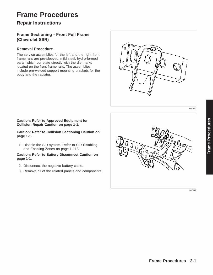
Frame Procedures Repair Instructions Frame Sectioning - Front Full Frame (Chevrolet SSR) Removal Procedure The service assemblies for the left and the right front frame rails are pre-sleeved, mild steel, hydro-formed parts, which correlate directly with the die marks located on the front frame rails. The assemblies include pre-welded support mounting brackets for the body and the radiator. Caution: Refer to Approved Equipment for Collision Repair Caution on page 1-1. Caution: Refer to Collision Sectioning Caution on page 1-1. 1. Disable the SIR system. Refer to SIR Disabling and Enabling Zones on page 1-118. Caution: Refer to Battery Disconnect Caution on page 1-1. 2. Disconnect the negative battery cable. 3. Remove all of the related panels and components. 907340 907342 Frame Procedures 2-1 Frame Procedures
Transcript of 8-19-04 - 1st Copy - genuinegmparts.com · Frame Procedures Repair Instructions Frame Sectioning -...
Frame ProceduresRepair Instructions
Frame Sectioning - Front Full Frame(Chevrolet SSR)
Removal ProcedureThe service assemblies for the left and the right frontframe rails are pre-sleeved, mild steel, hydro-formedparts, which correlate directly with the die markslocated on the front frame rails. The assembliesinclude pre-welded support mounting brackets for thebody and the radiator.
Caution: Refer to Approved Equipment forCollision Repair Caution on page 1-1.
Caution: Refer to Collision Sectioning Caution onpage 1-1.
1. Disable the SIR system. Refer to SIR Disablingand Enabling Zones on page 1-118.
Caution: Refer to Battery Disconnect Caution onpage 1-1.
2. Disconnect the negative battery cable.
3. Remove all of the related panels and components.
907340
907342
Frame Procedures 2-1
Fra
me
Pro
ced
ure
s
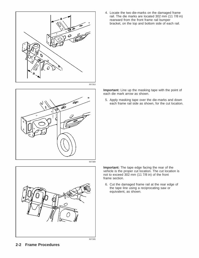
4. Locate the two die-marks on the damaged framerail. The die marks are located 302 mm (11 7/8 in)rearward from the front frame rail bumperbracket, on the top and bottom side of each rail.
Important: Line up the masking tape with the point ofeach die mark arrow as shown.
5. Apply masking tape over the die-marks and downeach frame rail side as shown, for the cut location.
Important: The tape edge facing the rear of thevehicle is the proper cut location. The cut location isnot to exceed 302 mm (11 7/8 in) of the frontframe section.
6. Cut the damaged frame rail at the rear edge ofthe tape line using a reciprocating saw orequivalent, as shown.
907353
907389
907395
2-2 Frame Procedures
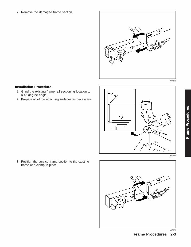
7. Remove the damaged frame section.
Installation Procedure1. Grind the existing frame rail sectioning location to
a 45 degree angle.2. Prepare all of the attaching surfaces as necessary.
3. Position the service frame section to the existingframe and clamp in place.
907398
907517
907520
Frame Procedures 2-3
Fra
me
Pro
ced
ure
s

Important: Inspect the frame measurementsthree-dimensionally to ensure proper position of theservice frame prior to welding. Refer to Dimensions -Frame.
4. Continuous-weld the upper and lower horizontaljoints from corner to corner.
5. Continuous-weld the inner and outer vertical jointsfrom corner to corner.
6. Clean and prepare all of the welded surfaces.7. Apply the sealers and anti-corrosion materials to
the repair area, as necessary. Refer toAnti-Corrosion Treatment and Repair.
8. Install all of the related panels and components.
Caution: Refer to Battery Disconnect Cautionon page 1-1.
9. Connect the negative battery cable.10. Enable the SIR system. Refer to SIR Disabling
and Enabling Zones on page 1-118.
907523
907524
907527
2-4 Frame Procedures

Frame Sectioning - Front Full Frame(Mid size utility 2002 - current,except S/T models)
Removal ProcedureThe re-designed frame assembly for the new S/TUtility is a mild, steel hydroformed frame assembly. Afront frame service section consisting of the leftand right frame ends, body, and radiator supportmounting brackets and front connecting cross tube isavailable. If damage permits, locate and cut off thefront 420 mm (161⁄2 in) portion of the frame using thedie-mark indicators as a guide. The front and rearbody mounts, radiator support mounts, steering gearand transmission cross-member can be orderedand replaced separately.
1. Remove all of the related panels and componentsincluding the front bumper assembly.
2. Locate the 2 die-marks on each frame. The diemarks are located 420 mm (161⁄2 in) rearwardfrom each front frame rail end on the topand bottom side of each rail.
1335267
1334889
1334929
Frame Procedures 2-5
Fra
me
Pro
ced
ure
s

Important: Line up the masking tape with the point ofeach die mark arrow.
3. Apply masking tape over the die-marks and downeach frame rail side as shown, for the cut location.
Important: The tape edge facing the rear of thevehicle is the proper cut location. The cut location isnot to exceed 420 mm (161⁄2 in) of the front framesection.
4. Cut each frame at the rear edge of the tape lineusing a reciprocating saw or equivalent, as shown.
5. Remove the damaged frame section.
1334933
1334935
1334938
2-6 Frame Procedures

Installation Procedure1. Grind the existing frame rail seam to taper seam
at a 45 degree angle.2. Prepare all of the attaching surfaces as necessary.3. Apply the weld-thru primer to all of the welded
surfaces.
4. Position the service frame section to the existingframe and clamp in place.
Important: Verify the frame measurements3-dimensionally to ensure proper position of theservice frame.
5. Continuous-weld the upper and lower horizontaljoints from corner to corner.
907517
1334941
1334946
Frame Procedures 2-7
Fra
me
Pro
ced
ure
s

Important: Verify the frame measurements3-dimensionally to ensure proper position of theservice frame.
6. Continuous-weld the inner and outer vertical jointsfrom corner to corner.
7. Clean and prepare all of the welded surfaces.8. Install all of the related panels and components.
Rail End Crush Cap Replacement - Front(Full size pickup 1999 andutility 2000 - current)
Removal Procedure
Important: The redesigned frame of the 1500 modelC/K pickup and C/K Utility, incorporates hydroformedtechnology. There is a replaceable, hydroformed,energy absorbing crush cap at the front of the frame.
1. Remove all of the related panels and thecomponents.
Important: If the crush cap (1) is bent or damaged inany way, replace the crush cap.
2. Visually inspect the damage. Use 3–dimensionalmeasuring in order to restore all of the damagerearward of the crush cap (1) to the factoryspecifications.
1334947
1334889
383487
2-8 Frame Procedures
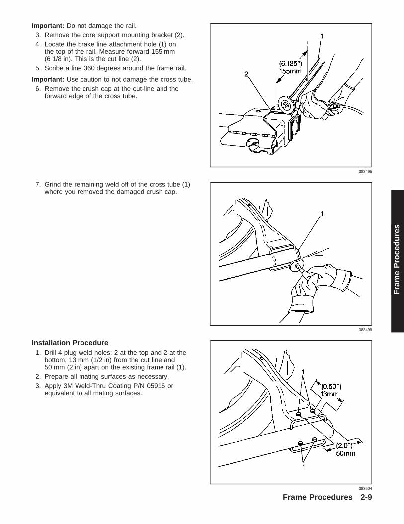
Important: Do not damage the rail.3. Remove the core support mounting bracket (2).4. Locate the brake line attachment hole (1) on
the top of the rail. Measure forward 155 mm(6 1/8 in). This is the cut line (2).
5. Scribe a line 360 degrees around the frame rail.
Important: Use caution to not damage the cross tube.6. Remove the crush cap at the cut-line and the
forward edge of the cross tube.
7. Grind the remaining weld off of the cross tube (1)where you removed the damaged crush cap.
Installation Procedure1. Drill 4 plug weld holes; 2 at the top and 2 at the
bottom, 13 mm (1/2 in) from the cut line and50 mm (2 in) apart on the existing frame rail (1).
2. Prepare all mating surfaces as necessary.3. Apply 3M Weld-Thru Coating P/N 05916 or
equivalent to all mating surfaces.
383495
383499
383504
Frame Procedures 2-9
Fra
me
Pro
ced
ure
s

Important:• The replacement bumper bracket (2) is a bolt-on
component that must be ordered separately.• Retain a gap of 11⁄2 times the metal thickness at
the butt joint (1) when attaching the service partto the vehicle.
4. Install and position the replacement crush capusing 3-dimensional measuring.
5. Tack weld the part into position at the initial plugweld holes.
6. Inspect the service part for proper dimensions.7. Stitch weld along the entire sectioning joint. Make
25 mm (1 in) welds along the seam with 25 mm(1 in) gaps between.
8. Complete the stitch weld.9. Clean and prepare the welded surfaces.
Important: Prior to refinishing, refer to GM 4901MRefinish Manual for recommended products. Donot combine paint systems. Refer to paintmanufacturer’s recommendations.10. Apply approved anti-corrosion primer.11. Position the new core support mounting bracket.
Weld the bracket in place according to thespecified dimensions.
12. Apply the sealers.13. Refinish the welded surfaces as necessary.14. Replace the related panels and the components.
Frame Module Replacement - Rear(Full size pickup 1999 - current)
Removal Procedure
Important: Perform all of the steps on both of the railsfor complete module replacement.
1. Remove all of the related panels and thecomponents.
2. Visually inspect all of the damage forward of therear module. Use 3-dimensional measuring inorder to restore the damage to the factoryspecifications.
3. Separate the center and the rear module at thefactory stitch weld (1) with a die grinder or anappropriate tool.
4. Pry the lower edge of cross tube bracket down (2)in order to allow the rear module to separate fromthe center module.
5. Remove the damaged rear module.
383506
383485
2-10 Frame Procedures

Installation Procedure
Important: Monitor the specified dimensions byfrequently performing 3-dimensional measuringthroughout the procedures.
1. Prepare all mating surfaces as necessary.2. Apply 3M Weld-Thru Coating P/N 05916 or
equivalent to all mating surfaces.3. Install and position the replacement module using
3-dimensional measuring.4. Restore the bracket flange (2) for a flush fit to the
new service part.5. Tack weld the rear module into position. Inspect
the service part for the proper dimensions.6. Stitch weld the entire sectioning joint.
Important: Prior to refinishing, refer to GM 4901MRefinish Manual for recommended products. Donot combine paint systems. Refer to paintmanufacturer’s recommendations.
7. Clean and prepare the welded surfaces.8. Apply approved anti-corrosion primer.9. Apply the sealers.
10. Refinish the welded surfaces as necessary.11. Install all of the related panels and the
components.
Bracket Replacement - Front Bumper(2500 Full size pickup 1999 - current)
1. Remove all related panels and components.2. Remove the damaged bumper bracket.3. Visually inspect the frame and restore all damage
to factory specifications using 3-dimensionalmeasuring.
Important: If the vehicle is equipped with tow hooks,discard original fasteners.
4. Align the replacement bracket lower bolt holeswith tow hook mounting locations and install thebolts (1) supplied.
383485
671498
Frame Procedures 2-11
Fra
me
Pro
ced
ure
s

5. Align the front edge of bracket with front edge offrame and mark upper bolt locations (1) on frame.
6. Rotate the bracket forward and drill 13 mm(1/2 in) holes in frame at upper bolt locations.
7. Rotate the bracket back into position.
Notice: Refer to Fastener Notice on page 1-1.
8. Install the fasteners supplied.
TightenTighten the torque bracket fasteners to70 N·m (52 lb ft).
671426
671416
671509
2-12 Frame Procedures

Bracket Replacement - Front Bumper(1500 Full size pickup 1999 andutility 2000 - current)
1. Remove all related panels and components.2. Remove damaged bumper bracket.
Important: Do not remove any material from end offrame rail.
3. Position the service template on the end of theframe rail. Use 3M’s Repositionable Adhesive orequivalent.
4. Drill three 13 mm (1/2 in) holes at locationsindicated on template.
Important: Prior to refinishing, refer to the PublicationGM 4901M-D-2000 “GM Approved Refinish Materials”for recommended products. Do not combine paintsystems. Refer to paint manufacturer’srecommendations.
5. Apply approved anti-corrosion primer to baremetal surfaces.
6. Position replacement bumper bracket.
Notice: Refer to Fastener Notice on page 1-1.7. Install the bolts.
TightenTighten the bolts to 50 N·m (37 lb ft).
Rail End Replacement - Rear(Full size utility 2000 - current)
Removal ProcedureThe service assembly for the left and the right rearframe rails is pre-sleeved, mild steel, hydro-formedparts. The assembly includes the body supportmounting bracket, a trailer hitch and rear bumpermounting holes.
671616
1527057
Frame Procedures 2-13
Fra
me
Pro
ced
ure
s

Important: The position of the rear cross-member (1)varies upon the wheel-base of the vehicle. Thisprocedure applies to all vehicles.
Caution: Refer to Approved Equipment forCollision Repair Caution on page 1-1.
Caution: Refer to Battery Disconnect Caution onpage 1-1.
Caution: Refer to Collision Sectioning Caution onpage 1-1.
1. Disconnect the negative battery cable.2. Remove all of the related panels and components.3. Repair as much of the damage as possible to
factory specifications.
4. Locate the sectioning location by measuring13 mm forward from the shipping slot (1) or330 mm forward of the frame rail end. Scribe aline around the rail.
1527872
1527047
1527052
2-14 Frame Procedures
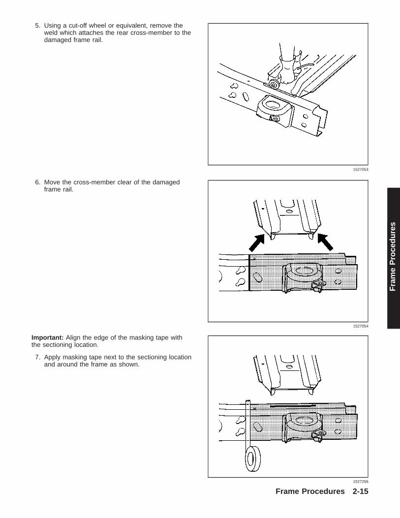
5. Using a cut-off wheel or equivalent, remove theweld which attaches the rear cross-member to thedamaged frame rail.
6. Move the cross-member clear of the damagedframe rail.
Important: Align the edge of the masking tape withthe sectioning location.
7. Apply masking tape next to the sectioning locationand around the frame as shown.
1527053
1527054
1527256
Frame Procedures 2-15
Fra
me
Pro
ced
ure
s

8. Cut the damaged frame rail along the sectioninglocation using a reciprocating saw or equivalent,as shown.
9. Remove the damaged frame section.
Installation Procedure1. Grind the existing frame rail sectioning location to
a 45 degree angle, as shown in the figure.2. Prepare all of the attaching surfaces as necessary.
1527702
1527064
1527065
2-16 Frame Procedures

3. Position the service frame section to the existingframe and clamp in place.
Important: Inspect the frame measurementsthree-dimensionally to ensure proper position of theservice frame prior to welding.
4. Continuous-weld the sectioning locationcompletely around the rail.
5. Lower and clamp the rear cross-member in place.
Important: Inspect the frame measurementsthree-dimensionally to ensure the proper position ofthe rear cross-member.
6. Continuous-weld the cross-member to theframe rail.
1527069
1527075
1527077
Frame Procedures 2-17
Fra
me
Pro
ced
ure
s
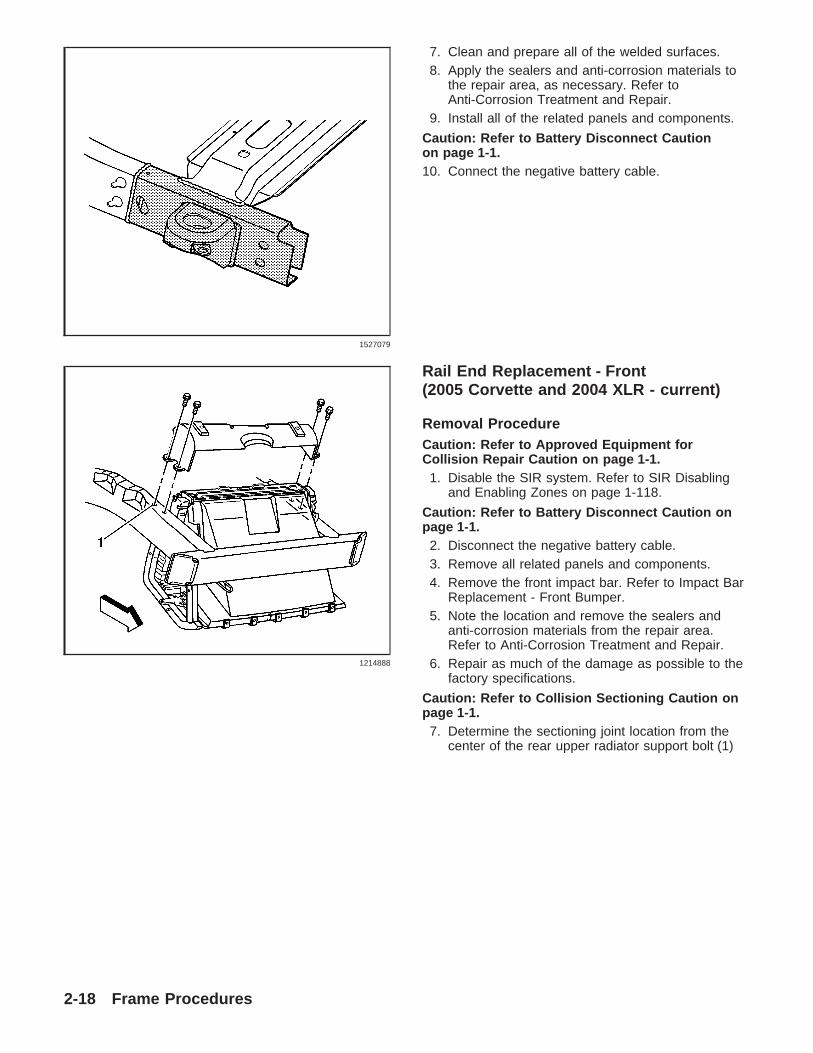
7. Clean and prepare all of the welded surfaces.8. Apply the sealers and anti-corrosion materials to
the repair area, as necessary. Refer toAnti-Corrosion Treatment and Repair.
9. Install all of the related panels and components.
Caution: Refer to Battery Disconnect Cautionon page 1-1.10. Connect the negative battery cable.
Rail End Replacement - Front(2005 Corvette and 2004 XLR - current)
Removal ProcedureCaution: Refer to Approved Equipment forCollision Repair Caution on page 1-1.
1. Disable the SIR system. Refer to SIR Disablingand Enabling Zones on page 1-118.
Caution: Refer to Battery Disconnect Caution onpage 1-1.
2. Disconnect the negative battery cable.3. Remove all related panels and components.4. Remove the front impact bar. Refer to Impact Bar
Replacement - Front Bumper.5. Note the location and remove the sealers and
anti-corrosion materials from the repair area.Refer to Anti-Corrosion Treatment and Repair.
6. Repair as much of the damage as possible to thefactory specifications.
Caution: Refer to Collision Sectioning Caution onpage 1-1.
7. Determine the sectioning joint location from thecenter of the rear upper radiator support bolt (1)
1527079
1214888
2-18 Frame Procedures

8. Measure 67 mm (2 5/8 in) (a) forward from thecenter of the rear upper radiator support bolt.
9. Mark the top of the frame rail at the sectioninglocation.
10. At the mark align a sliding square or similartool (1) square to surface to the vertical wallsof the frame rail.
11. Scribe a line to both sides of the frame rail.
12. Apply masking tape (1) to the scribe linecompletely around the frame rail.
1198416
1198420
1198423
Frame Procedures 2-19
Fra
me
Pro
ced
ure
s
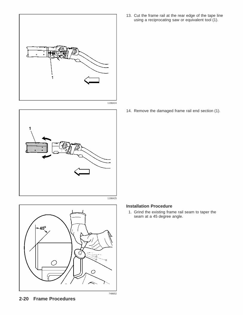
13. Cut the frame rail at the rear edge of the tape lineusing a reciprocating saw or equivalent tool (1).
14. Remove the damaged frame rail end section (1).
Installation Procedure1. Grind the existing frame rail seam to taper the
seam at a 45 degree angle.
1198424
1198425
748652
2-20 Frame Procedures

2. Clean and prepare all of the welded matingsurfaces.
3. Apply 3M weld-thru coating P/N 05916 orequivalent as necessary to all bare metal surfaces
4. Position the service frame section (1) to theexisting frame.
5. Maintain a gap of one and one half frame railmetal thickness at the sectioning joint (1) andclamp in place.
6. Inspect the frame measurementsthree-dimensional to ensure proper position of theservice frame.
1198427
1198429
Frame Procedures 2-21
Fra
me
Pro
ced
ure
s

Important: Use a 25-mm (1-in) stitch weld to avoidminimal heat distortion.
7. Using a MIG welder, weld completely around thesleeve joint.
8. Install the front impact bar. Refer to Impact BarReplacement - Front Bumper.
9. Apply the sealers and anti-corrosion materials tothe repair area. Refer to Anti-Corrosion Treatmentand Repair.
Important: DO NOT top coat any bonding surface.Use primer only on bonding surfaces. Refer toadhesive manufacturer’s recommendations.10. Paint the repair area. Refer to Basecoat/Clearcoat
Paint Systems.11. Install all related panels and components.
Caution: Refer to Battery Disconnect Caution onpage 1-1.12. Connect the negative battery cable.13. Enable the SIR system. Refer to SIR Disabling
and Enabling Zones on page 1-118.
1198433
2-22 Frame Procedures

©2004 General Motors Corporation. All Rights ReservedInformation cutoff date 09-18-04.
GM Service Publications are intended for use by professional technicians, not a ″Do-It-Yourselfer.″ They arewritten to inform these technicians of conditions that may occur on some vehicles, or to provide information that
could assist in the proper service of a vehicle. Properly trained technicians have the equipment, tools, safetyinstructions, and know-how to do a job properly and safely. If a condition is described, DO NOT assume that the
publication applies to your vehicle, or that your vehicle will have that condition. Means (including but not limited toelectronic, mechanical, photocopying, and recording) without the prior written permission of General Motors
corporation. This applies to all text, illustrations, and tables.