7Zt-GENERAL RAD I 0
8
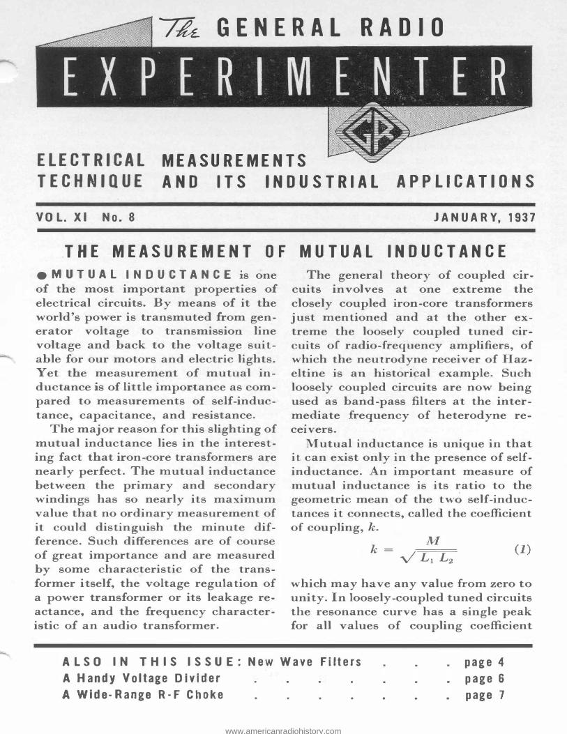
GENERAL RAD I 0 ELECTRICAL TECHNIQUE MEASUREMENTS AND ITS INDUSTR IAL APPLICATIONS VOL. XI No. 8 JANUARY, 1937 THE MEASUR EMENT OF MU TUAL INDUCTANCE e M U T U A L I N D U C T A NC E is one of the most importan properties of electrical circuits. By means of it the world's power is transmuted om gen- erator voltage to transmission line voltage and back to the voltage suit- able for our motors and electric lights. Yet the measurement of mutual in- ductance is of little imporance as com- pared to measurements of self-induc- tance, capacitance, and resistance. The major reason for this slighting of mutual inductance lies in the interest- ing fact that iron-core transformers are nearly perfect. The mutual inductance between the primary and secondary windings has so nearly its maximum value that no ordinary measurement of it could distinguish the minute dif- ference. Such differences are of course of great importance and are measured by some characteristic of the trans- former itself, the voltage regulation of a power transformer or its leakage re- actance, and the equency character- istic of an audio transformer. The general theory of coupled cir- cuits involves at one extreme the closely coupled iron-core transformers just mentioned and at the other ex- treme the loosely coupled tuned cir- cuits of radio-equency amplifiers, of which the neutrodyne receiver of Haz- eltine is an historical example. Such loosely coupled circuits are now being used as band-pass lters at the inter- mediate equency of heterodyne re- ceivers. Mutual inductance is unique in that it can exist only in the presence of self- inductance. important measure of mutual inductance is its ratio to the geometric mean of the tw o self-induc- tances it connects� called the coefficient of coupling, k. k = M (1) V L1 L2 which may have any value om zero to unity. In loosely-coupled tuned circuits the resonance curve has a single peak for all values of coupling coefficient ALSO IN THIS ISSUE: Ne w Wave Filters A Handy Voltage Divider page 4 page 6 page 7 A Wide-Range R-F Choke www.americanradiohistory.com
Transcript of 7Zt-GENERAL RAD I 0
7Zt- GENERAL RAD I 0
ELECTRICAL
TECHNIQUE
MEASUREMENTS
AND ITS INDUSTRIAL APPLICATIONS
VOL. XI No. 8 JANUARY, 1937
THE MEASUREMENT OF MUTUAL INDUCTANCE
e M U T U A L I N D U C T A N C E is one of the most important: properties of electrical circuits. By means of it the world's power is transmuted from generator voltage to transmission. line voltage and back to the voltage suitable for our motors and electric lights. Yet the measurement of mutual inductance is of little impor.>:t:an.ce as compared to measurements of self-inductance, capacitance, and resistance.
The major reason for this slighting of mutual inductance lies in the interesting fact that iron-core transformers are nearly perfect. The mutual inductance between the primary and secondary windings has so nearly its maximum value that no ordinary measurement of it could distinguish the minute difference. Such differences are of course of great importance and are measured by some characteristic of the transformer itself, the voltage regulation of a power transformer or its leakage reactance, and the frequency characteristic of an audio transformer.
The general theory of coupled circuits involves at one extreme the closely coupled iron-core transformers just mentioned and at the other extreme the loosely coupled tuned circuits of radio-frequency amplifiers, of which the neutrodyne receiver of Hazeltine is an historical example. Such loosely coupled circuits are now being used as band-pass :filters at the intermediate frequency of heterodyne receivers.
Mutual inductance is unique in that it can exist only in the presence of selfinductance. An important measure of mutual inductance is its ratio to the geometric mean of the two self-inductances it connects� called the coefficient of coupling, k.
k = M (1) V L1 L2
which may have any value from zero to unity. In loosely-coupled tuned circuits the resonance curve has a single peak for all values of coupling coefficient
ALSO IN THIS ISSUE: New Wave Filters
A Handy Voltage Divider
page 4
page 6
page 7 A Wide-Range R-F Choke
www.americanradiohistory.com
a:: � a.. >< �
less than a so-called critical coupling. L A larger coupling coefficient results in a flattened top with the steepness of the sides maintained. The measurement of this sma l mutual inductance is of considerable importance in the adjustment of i-f filters.
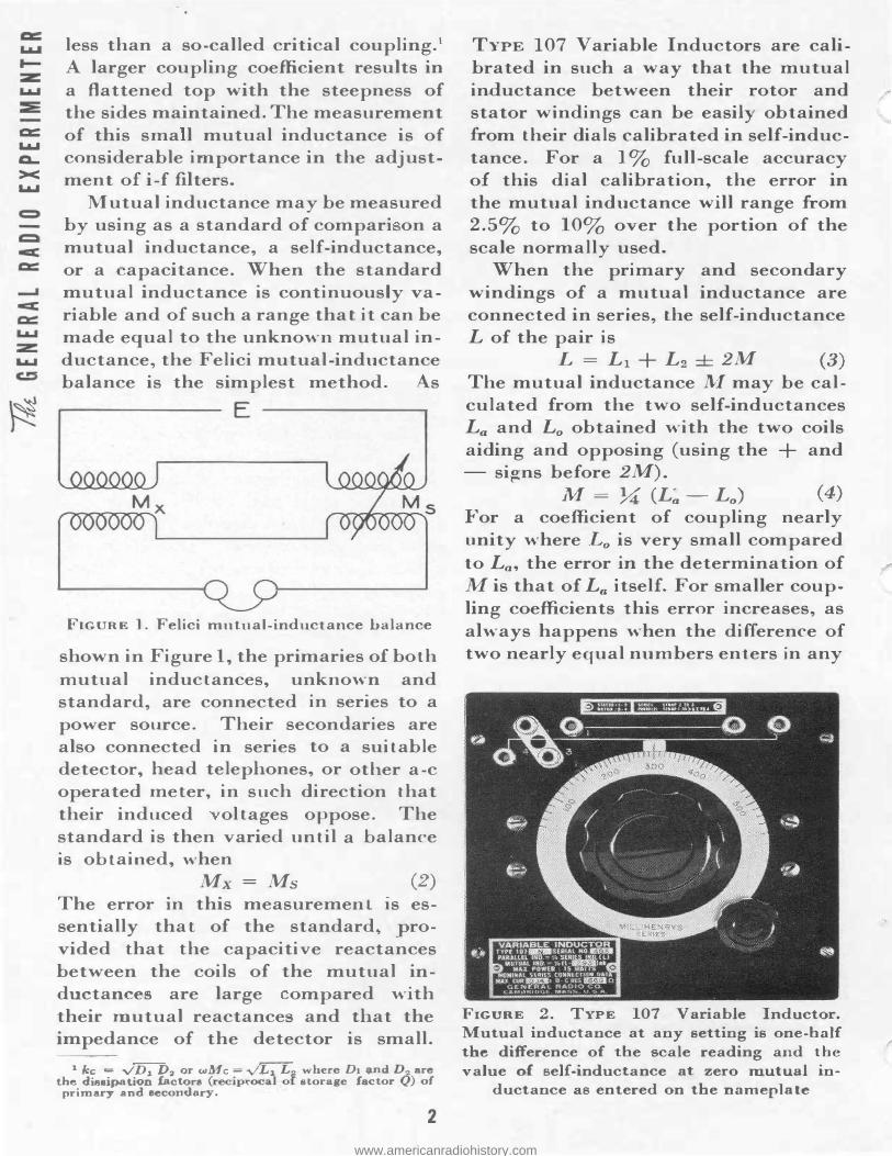
Mutual inductance may be measured by using as a standard of com pari on a mutual inductance, a self-inductance, or a capacitance. When the standard mutual induc-tance is continuously variable and of such a range that it can be made equal to the unknown mutual inductance, the Felici mutual-inductance balance is the simplest method. As
E
FIGURE 1. Felici mutual-inductance balance
shown in Figure l, the primaries of both mutual inductances, unknown and standard, are connected in series to a power source. Their secondaries are also connected in series to a suitable detector, head telephones, or other a-c operated meter, in su h direction that their induced ol tages oppose. The standard is then varied until a balance is obtained, ·when
Mx =Ms (2) The error in this measurement is essentially that of the standard� provided that the capacitive reactances between the coils of the mutual inductances are large om.pared with their mutual reactances and -r:hat the impedance of the detector is small.
1 kc = vDi D2 or wMc = �2 where D1 lillld DA are the dieeipation !actora (recip.-ocal of storage factor f.,!) of
pritnary and seco11dary.
2
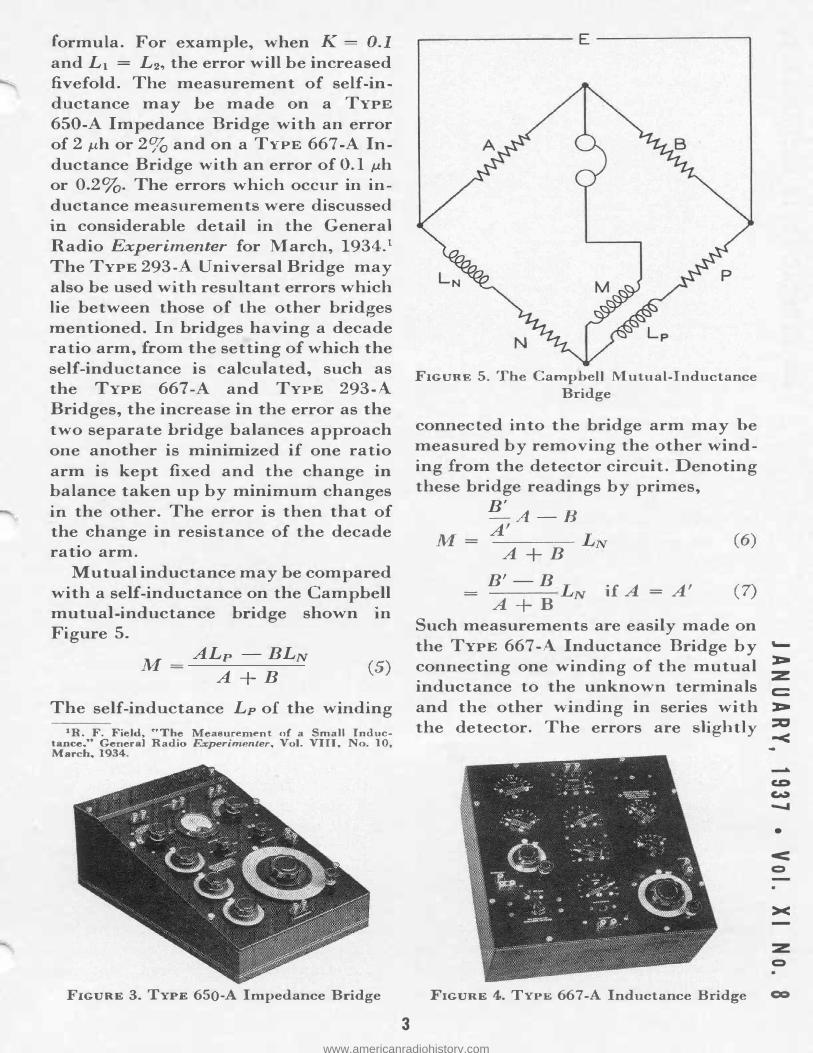
TYPE 107 Variable Inductors are calibrated in such a way that the mutual inductance between their rotor and stator windings can be easily obtained from their dials calibrated in self-inductance. For a 1 % full-scale accuracy of this dial calibration, the error in the mutual inductance will range from 2.5% to 10% over the portion of the scale normally used.
When the primary and secondary windings of a mutual inductance are connected in series, the self-inductance L of the pair is
L = Li + L2 ± 2M (3) The mutual inductance M may be calculated from the two self-inductances La and L0 obtained with the two coils aiding and opposing (using the + and - signs before 2M).
1� = 7.;t (L� - L0) (4) For a coefficient of coupling nearly unity where L0 is very small compared to L0, the error in the determination of Mis that of L0 itself. For smaller coupling coefficients 1:his error increases, as always happens when the difference of two nearly equal numbers en1:ers in any
FIGURE 2. TYPE 107 Variable Inductor. Mutual inductance at any setting is one-half the difference of t:he scale reading and t.he value of self-inductance at zero mutual in-
ductance as entered on the namep]a te
www.americanradiohistory.com
formula. For example, when K = 0.1 and L1 = L2, the error will be increased fivefold. The measurement of self-inductance may be made on a TYPE 650-A Impedance Bridge with an error of 2 1-ih or 2% and on a TYPE 667-A Inductance Bridge with an error of 0.1 µh or 0.23. The errors which occur in inductance measurements were discussed in considerable detail in the Genera] Radio Experimenter for March, 1934.1 The TYPE 293- Universal Bridge may also be used with resultant errors which lie between those of the other bridges mentioned. In bridges having a decade ratio arm, from the setting of which the self-inductance is calculated, such as the TYPE 667 -A and TYPE 293-A Bridges, the increase in -the error as the two separate bridge balances approach one ano"ther is m.inim.ized if one ratio arm is kept fixed and the change in balance taken up by minim.um changes in the other. The error is then that of the change in resis"tance of the decade ratio arm..
Mutual inductance may be compared with a seH-inductan.ce on the Campbell mutual-inductance bridge shown in Figure 5.
M = ALp -BLN
A+B (5)
The self-inductance LP of the winding
1R. F. Field, .. The Measurement of a Small Inductance ... General Radio Experim.enler. Vol. VIII, No. 10, March, 1934.
FIGURE 3. TYPE 650-A Impedance Bridge
3
FIGURE 5. The Campbell Mutual-Inductance Bridge
connected into the bridge arm may he measured by removing the other winding from the detector circuit. Denoting these bridge readings by primes,
B' -A-B A'
M= ----- LN A+B
(6)
B'-B --- L if A = A' (7) A+B N
Such measurements are easily made on the TYPE 667 -A Inductance Bridge by connecting one winding of the mutual inductance to the unknown terminals and the other winding in series with the detector. The errors are slightly
> :z: c::: > :a <
•
< c:>
><
::z:: Q
FIGURE 4. TYPE 667-A Inductance Bridge CCI
www.americanradiohistory.com
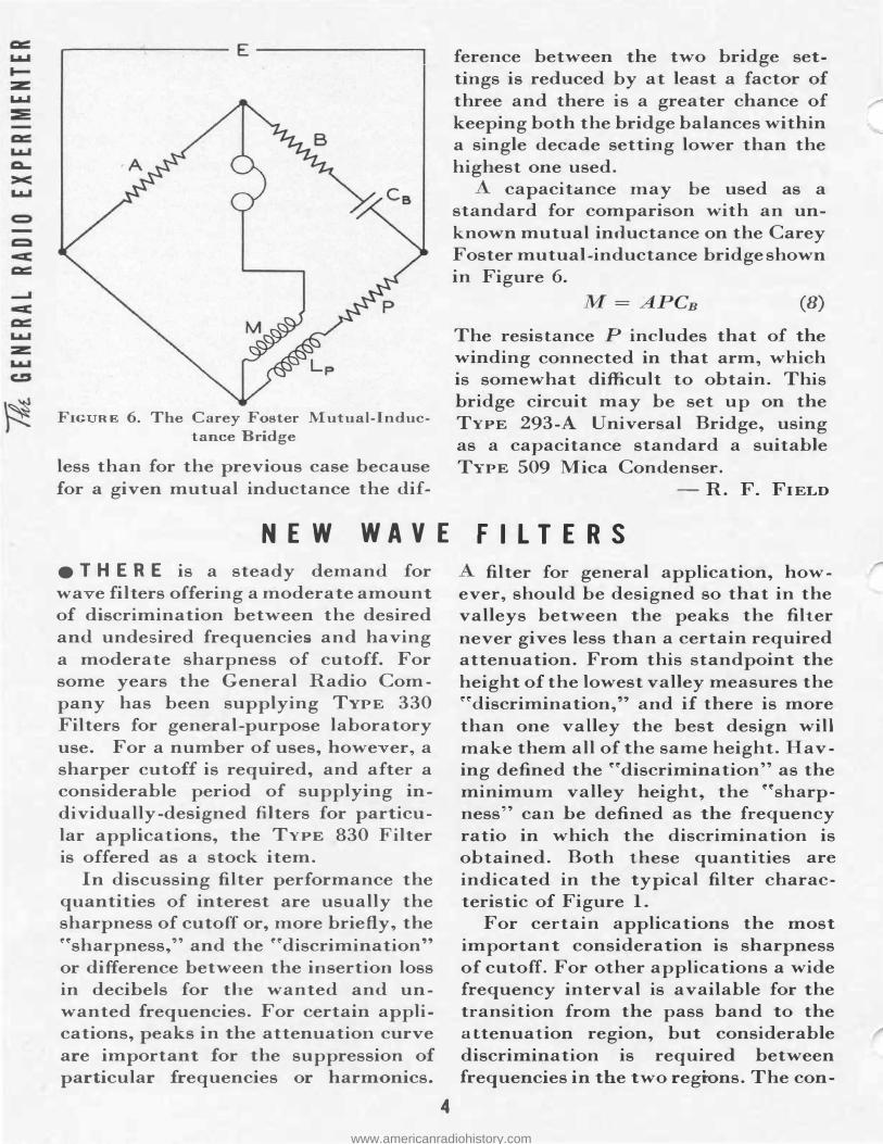
FIG RE 6. The Carey Foster Mutual-Inductance Bridge
less than for the previous case because for a given mutual inductance the dif-
NEW WAVE
e THERE is a steady demand for wa e filters offering a moderate amount of discrimination between the desired and unde ired frequencies and having a moderate sharpness of cutoff. For some years the General Radio Company has been supplying TYPE 330 Filters for general-purpose laboratory use. For a number of uses, howe er, a sharper cutoff is required, and after a considerable period of supplying individually-designed filters for particular applications, the TYPE 830 Filter is offered as a stock item.
In discussing filter performance the quantities of interest are usually the sharpness of cutoff or, more briefly, the r�sharpness/' and the r�discrimination" or difference between the insertion loss in decibels for the wanted and unwanted frequencies. For certain. applications, peaks in the attenuation. curve are important for the suppression. of particular frequencies or harmonics.
4
feren.ce between t:he two bridge settings is reduced by at least a factor of three and t:here is a greater chance of keeping both the bridge balances within a single decade setting lower than the highest one used.
capacitance may be used as a standard for comparison with an unknown mutual inductance on the Carey Foster mutual-inductance bridge shown in Figure 6.
(8) The resistance P in.eludes that of the winding connected in that arm, which is somewhat difficult to obtain. This bridge circuit may be set up on the TYPE 293-A Universal Bridge, using as a capacitance standard a suitable TYPE 509 Mica Condenser.
- R. F. FIELD
FI LTERS
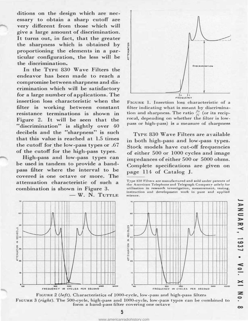
filter for general application, however, should be designed so that in the valleys between the peaks the filter never gives less than a certain required attenuation.. From this standpoint the height of the lowest valley measures the ��discrimination," and if there is more than one valley the best design will make them all of the same height. Having defined the ��discrimination" as the minimum valley height., the ''sharpness'' can. he defined as the frequency ratio in which the discrimination is obtained. Both t;hese quan.thies are indicated in the typical filter characteristic of Figure 1.
For certain applications the most important consideration is sharpness of cutoff. For ot:her applications a wide frequency interval is available for the transition from the pass band to the a ttenuat;ion region, but considerable discrimination is required between frequencies in the two regions. The con-
www.americanradiohistory.com
ditions on the design which are necessary to obtain a sharp cutoff are very different from those which will give a large amount of discrimination. It turns out, in fact, that the greater the sharpness which is obtained by proportioning the elements in a particular configuration, the less will he the discrimination.
In the TYPE 830 Wave -i ilters the endeavor has been made to reach a compromise between sharpness and discrimination which will he satisfactory for a large nUID.ber of applications. The insertion loss characteristic when the filter is working between constant resistance terminations is shown in Figure 2. It will be seen that the ffdiscrimination" is slightly over 40 decibels and the ff sharpness"' is such that this value is reached at 1.5 times the cutoff for_the low-pass types or .67 of the cutoff for the high-pass types.
High-pass and low-pass types can be used in tandem to provide a bandpass filter where the inter al to be covered is one octave or more. The attenuation characteristic of such a combinat"on is shown in Figure 3.
70
60
..., U'J ..J UJ ID
:rl.o 0
IO
r-___
0 100
- w. N. TUTTLE
I
l/ I
!\ J � \ 1'....
I \ I 7
soo •ooo SOOQ FREQUE�CY IN CVCLES PE� SECONO
L--'-"'"'
10000
�-------'
fo ft FREQUENCY
FIGURE 1. Insertion los characteristic of a filter indicat:ing what is meant by di crimination and sharpness. The ratio �; (or its recip
rocal, depending on whether the filter is lowpass or high-pass) is a measure of harpness
TYPE 830 Wave Filters are a ailahle in both high-pas and low-pass types. Sto k models have cut-off frequencies of either 500 or 1000 cycles and image impedances of either 500 or 5000 ohms. Complete specifications are gi en on page 114 of Catalog J.
T pe 830 Filt_ers are manufactured and sold under paten ls of the American Telephone and Telegraph Company oleJy for utilization in research investigation, measurement, te ting, instruction and development work in pure and applied
cience.
z 0
u � "° :> :z UJ f.... ... 20
10
0 -
�
�
'
I\ � \
I'-.__ L-l..-
I
\ I \ I
500 iOOO 5000 FREO.UENCV IN CYCLES PER SECOND
IOOOO
FIGURE 2 (left). haracteristi of 1000-c cle, ]ow-pas and high-pa filter
FIG RE 3 (right). The 500-cycle, high-pa and 1000-cycle, low-pa s typ s can be combin d to form a band-pa s filter covering one octave
5
-
•
< C)
><
:z 0
co
www.americanradiohistory.com
A HA NDY V OLTAGE DIVIDER
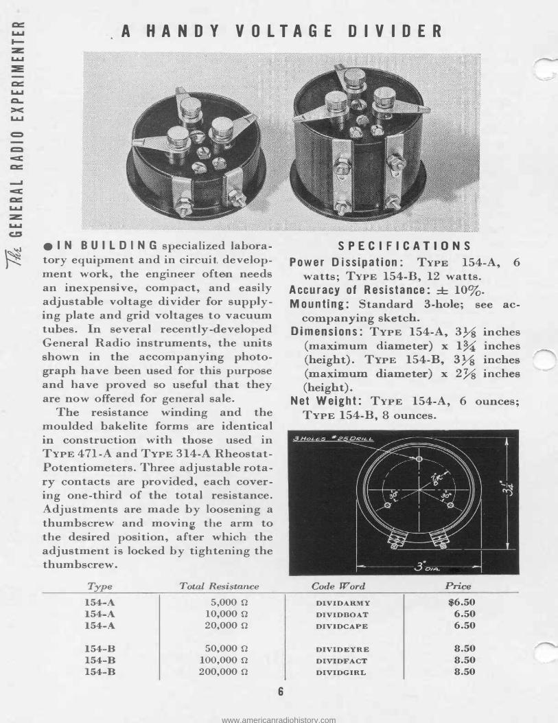
e I N B U I L D I N G specialized laboratory equipment and in circuit. development work, the engineer often needs an inexpensive, compact, and easily adjustable voltage divider for supplying plate and grid voltages to vacuum tubes. In several recently-developed General Radio instrUIDents, the units shown in the accompanying photograph have been used for this purpose and have proved so useful that they are now offered for general sale.
The resistance winding and the moulded bakelite forms are identical in construction with those used in TYPE 471-A and TYPE 314-A RheostatPotentiometers. Three adjustable rotary contacts are provided, each covering one-third of the total resistance. Adjustments are made by loosening a thumbscrew and moving the arm to the desired posit.ion, after which the adjustment is locked by tightening the thumbscrew.
Type Total Resistance 154-A 5,ooo n 154-A io,ooo n 154-A 20,000 n
154-B 50,000 n 154-B lOO,ooo n 154-B 200,000 n
6
S PEC IFICATIONS
Pow er Dissipation: TYPE 154-A, 6 watts; TYPE 154-B, 12 watts.
Accuracy of Resistance: ± 10%. Mounting: Standard 3-hole; see ac
companying sketch. Dimensions: TYPE 154-A, 3Ys inches
(maximum diameter) x 1% inches (height). TYPE 154-B, 3Ys inches (maximum diameter) x 2Ys inches (height).
Net Weight: TYPE 154-A, 6 ounces; TYPE 154-B, 8 ounces.
Code Word Price DIVIDA.R.MY $6.50 DIVIDBOAT 6.50 DIVIDCAPE 6.50
DIVIDEYRE 8.50 DIVIDFACT 8.50 DIVIDGIRL 8.50
www.americanradiohistory.com
A WIDE-R A NGE R-F C HOKE
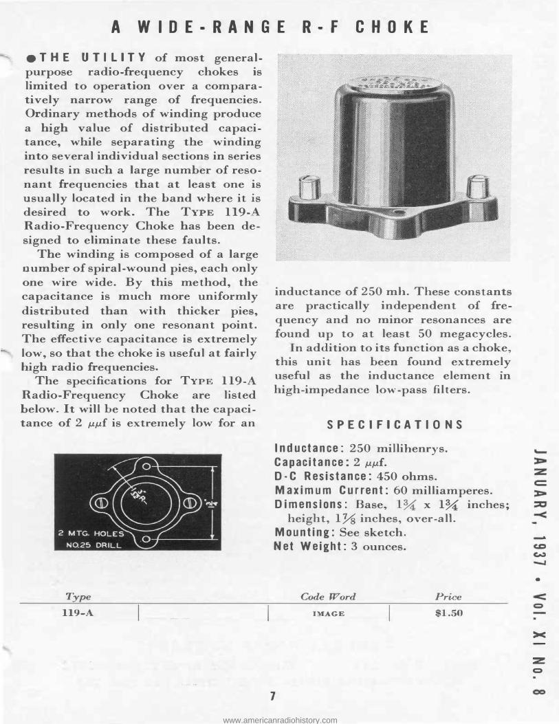
•THE UTILITY of most generalpurpose radio-frequency chokes is limited to operation over a comparatively narrow range of frequencies. Ordinary methods of winding produce a high value of distributed capacitance, while separating "the winding into several individual sections in series results in such a large number of resonant frequencies that at least one is usually located in the hand where it is desired to work. The TYPE 119-A Radio-Frequency Choke has been designed to eliminate these faults.
The winding is composed of a large number of spiral-wound pies, each only one wire wide. By this method, the capacitance is much more uniformly distributed than with thicker pies, resulting in only one resonant point. The effective capacitance is extremely low, so that the choke is useful at fairly high radio frequencies.
The specifications for TYPE 119-A Radio-Frequency Choke are listed below. It will he noted that the capacitance of 2 µµf is extremely low for an
Type
119-A
inductance of 250 mh. These constants are practically independent of frequency and no minor resonances are found up to at least 50 megacycles.
In addition to its function as a choke '
this uni"t has been found extremely useful as the inductance element in high-impedance low-pass filters.
SPECIFICA TIO NS
Inductance: 250 millihenrys. Capacitance: 2 µµf. D-C Resistance: 450 ohms. Maximum Current: 60 milliamperes. Dimensions: Base, l� x l� inches;
height, lYs inches, over-all. Mounting: See sketch. Net Weight: 3 ounces.
Code Word
IMAGE
1
Price
$1.50
-
•
>< -
::z Q
www.americanradiohistory.com
MISCELLANY
eA M O N G RECENT VIS IT ORS to the General Radio Laboratories was Dr. Georg Keina th, Director of the Instrument Laboratories of Siemens and Halske. Dr. ein.ath is the author of ''Die Technik Electrische Messgerate/' a well-known text on electrical mea uri:ng instruments.
eTHE "R.M.A. EN G I NEER," published by the Engineering Di vision of the Radio anufacturers' Association made its first appearance with the Fall Meeting of the IRE at Rochester. This publication, which will carry standardization reports and similar data, as well as technical articles, will be issued three times a year. olume I,
o. 1 is an achievement of which the board of editors may be proud.
ePERIO DIC ALLY i t b e co me s necessary to revise the Experimenter and catalog mailing list. Shortly after you receive this issue of the Experimenter, a post card 'tsubscription" renewal form will reach you. The revised G-R mailing list will he made up from the returns received from these cards.
In order to insure your name remaining on the list, the return card should be filled in completely and mailed promptly.
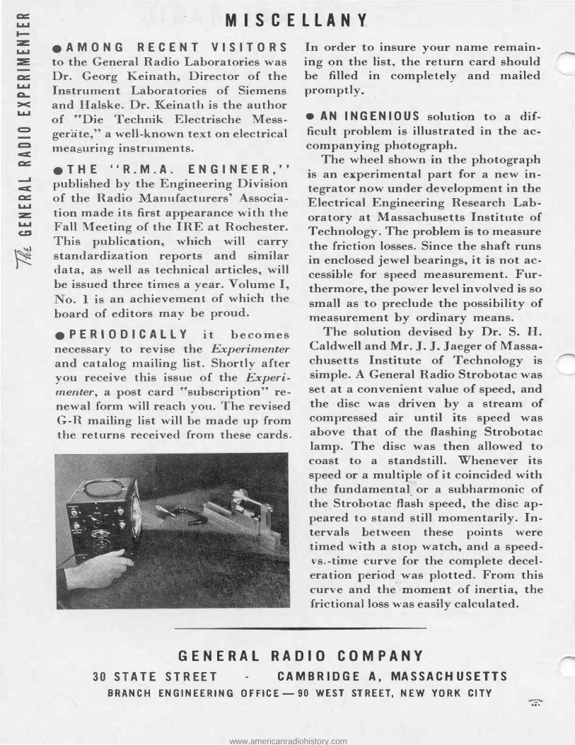
•AN INGENIOUS solution to a difficult problem is illustrated in the accompanying photograph.
The wheel shown in the photograph is an e](perimental part for a new integrator now under development in the Electrical Engineering Research Laboratory at Massachusetts Institute of Technology. The problem is to measure the friction. losses. Since the shaft runs in enclosed jewel bearings, it is not accessible for speed measurement. Furthermore, the power level involved is so small as to preclude the possibility of measurement by ordinary means.
The solution devised by Dr. S. H. Caldwell and Mr. J. J. Jaeger of Massachusetts Institute of Technology is simple. A General Radio Strobotac was set at a convenient value of speed, and the disc was driven by a stream of compressed air until its speed was above that of the fl.ashing Strobotac lamp. The disc was then allowed to coast to a standstill. Whenever its speed or a multiple of it coincided with the fundamental. or a subharmonic of the Strohotac flash speed, the disc appeared to stand still momentarily. Intervals between these points were timed with a stop watch, and a speedvs.-time curve for the complete deceleration period was plotted. From this curve and the
. moment of inertia, the
frictional loss was easily calculated.
GENERAL RADIO COMPANY 30 STATE STREET CAMBRIDGE A, MASSACHUSETTS
BRANCH ENGINEERING OFFICE-90 WEST STREET, NEW YORK CITY .-·:r: ..
...
www.americanradiohistory.com