7th Generation Intel® Core™ Processor, Intel® Celeron ... DC Specifications.....19 4.4.6 Vcc PLL...
23
Document Number: 335437-002 7th Generation Intel® Core™ Processor, Intel® Celeron® Processor, and Intel® Xeon® Processor E3 v6 Family Desktop, Workstation, and Mobile Platforms Datasheet Addendum April 2017
Transcript of 7th Generation Intel® Core™ Processor, Intel® Celeron ... DC Specifications.....19 4.4.6 Vcc PLL...

Document Number: 335437-002
7th Generation Intel® Core™ Processor, Intel® Celeron® Processor, and Intel® Xeon® Processor E3 v6 Family Desktop, Workstation, and Mobile Platforms Datasheet Addendum April 2017

7th Generation Intel® Core™ Processor, Intel® Celeron® Processor, and Intel® Xeon® Processor E3 v6 Family Desktop, Workstation, and Mobile Platforms Datasheet Addendum April 2017 2 Document Number: 335437-002
You may not use or facilitate the use of this document in connection with any infringement or other legal analysis concerning Intel products described herein. You agree to grant Intel a non-exclusive, royalty-free license to any patent claim thereafter drafted which includes subject matter disclosed herein.
No license (express or implied, by estoppel or otherwise) to any intellectual property rights is granted by this document.
All information provided here is subject to change without notice. Contact your Intel representative to obtain the latest Intel product specifications and roadmaps.
The products described may contain design defects or errors known as errata which may cause the product to deviate from published specifications. Current characterized errata are available on request.
Copies of documents which have an order number and are referenced in this document may be obtained by calling 1-800-548-4725 or by visiting: http://www.intel.com/design/literature.htm
Intel technologies’ features and benefits depend on system configuration and may require enabled hardware, software or service activation. Learn more at http://www.intel.com/ or from the OEM or retailer.
Intel® Turbo Boost Technology requires a PC with a processor with Intel Turbo Boost Technology capability. Intel Turbo Boost Technology performance varies depending on hardware, software and overall system configuration. Check with your PC manufacturer on whether your system delivers Intel Turbo Boost Technology. For more information, see http://www.intel.com/technology/turboboost.
No computer system can be absolutely secure.
Intel, Intel Core, Celeron, Pentium, Xeon and the Intel logo are trademarks of Intel Corporation in the U.S. and/or other countries.
*Other names and brands may be claimed as the property of others.
Copyright © 2017, Intel Corporation. All rights reserved.

7th Generation Intel® Core™ Processor, Intel® Celeron® Processor, and Intel® Xeon® Processor E3 v6 Family Desktop, Workstation, and Mobile Platforms
April 2017 Datasheet Addendum Document Number: 335437-002 3
Contents 1.0 Introduction ............................................................................................................................................ 6
1.1 Terminology ...................................................................................................................................................... 7 1.2 Reference Documents ................................................................................................................................ 8 1.3 Supported Package and Die Plan........................................................................................................ 8
2.0 Interface ................................................................................................................................................ 10 2.1 System Memory Interface and Supported Technology .................................................... 10
3.0 Thermal Management .................................................................................................................... 11 3.1 Processor Thermal Management...................................................................................................... 11 3.2 S/H-Processor Line TDP Specifications ........................................................................................ 11 3.3 H-Processor Line TDP Specifications ............................................................................................. 12
4.0 Electrical Specifications ................................................................................................................ 13 4.1 Processor Intel® Architecture Core (VCC) and VCCGT/VCCGTX Current
Specifications ................................................................................................................................................ 13 4.2 H-Processor Power Rails ........................................................................................................................ 13 4.3 Thermal Design Current (TDC) Specification .......................................................................... 14 4.4 H-Line Platform Power Map and Rail Requirements ........................................................... 16
4.4.1 IMVP8 Voltage and Current Requirements - H-Line ........................................ 16 4.4.2 GT2/3/4 Graphics Frequency .......................................................................................... 17 4.4.3 H-Processor Line Thermal and Power Specifications ...................................... 17 4.4.4 Processor Power Rails DC Specifications ................................................................. 18 4.4.5 VccSA DC Specifications........................................................................................................ 19 4.4.6 VccPLL DC Specifications ....................................................................................................... 19 4.4.7 Package Mechanical Specifications .............................................................................. 19
4.5 USB On-The-Go Specification ............................................................................................................ 20
5.0 Processor Listings ............................................................................................................................ 21

7th Generation Intel® Core™ Processor, Intel® Celeron® Processor, and Intel® Xeon® Processor E3 v6 Family Desktop, Workstation, and Mobile Platforms Datasheet Addendum April 2017 4 Document Number: 335437-002
Figures Figure 1. H-Processor and S-Processor Line Platform ............................................................................... 6 Figure 2. Processor Platform Power Map - H–Line .................................................................................... 16
Tables Table 1. Terminology ...................................................................................................................................................... 7 Table 2. Reference Documents ................................................................................................................................ 8 Table 3. Processor Lines Package and Die Plan ............................................................................................ 8 Table 4. TDP Specifications ...................................................................................................................................... 11 Table 5. Package Intel® Turbo Boost Technology Specifications ................................................. 12 Table 6. Processor Graphics (VccGT and VccGT-X) Supply Current Specifications .......... 13 Table 7. Thermal Design Current (TDC) Specification (Page 1 of 2) .......................................... 14 Table 8. General Processor VR Parameters for the H-line ................................................................. 16 Table 9. GT2/3/4 Graphics Frequency (H -Processor Line) ............................................................... 17 Table 10. TDP Specifications (H-Processor Line) ......................................................................................... 17 Table 11. Package Intel® Turbo Boost Technology Specifications (H-Processor Line) .... 17 Table 12. Processor Intel® Architecture Core (Vcc) Active and Idle Mode DC Voltage
and Current Specifications ................................................................................................................... 18 Table 13. Processor Graphics (VccGT and VccGT-X) Supply DC Voltage and Current
Specifications ................................................................................................................................................ 18 Table 14. System Agent (VccSA) Supply DC Voltage and Current Specifications ................ 19 Table 15. Processor PLL_OC (VccPLL_OC) Supply DC Voltage and Current
Specifications ................................................................................................................................................ 19 Table 16. Package Mechanical Attributes.......................................................................................................... 19 Table 17. U-Processor Family Listing/Package BGA1356 ...................................................................... 21 Table 18. S-Processor Family Listing/Package LGA1151 ....................................................................... 22 Table 19. H-Processor Family Listing/Package BGA1440 ...................................................................... 23

7th Generation Intel® Core™ Processor, Intel® Celeron® Processor, and Intel® Xeon® Processor E3 v6 Family Desktop, Workstation, and Mobile Platforms
April 2017 Datasheet Addendum Document Number: 335437-002 5
Revision History
Date Revision Description
April 2017 002 • Updated Table 18 and Table 19. - Added new SKUs
• Updated Chapter 2.0
January 2017 001 Initial release.
§

Introduction
7th Generation Intel® Core™ Processor, Intel® Celeron® Processor, and Intel® Xeon® Processor E3 v6 Family Desktop, Workstation, and Mobile Platforms Datasheet Addendum April 2017 6 Document Number: 335437-002
1.0 Introduction
This datasheet is a supplement to the 7th Generation Intel® Processor Families for H Platforms – Datasheet and 7th Generation Intel® Processor Families for S Platforms – Datasheet. It contains more electrical specifications, signal information, interface functional descriptions, more feature information, and configuration registers pertinent to the implementation and operation of the H-processor line and S-processor line.
The H-processor line and S-processor line are offered in a 2-Chip Platform and connected to a discrete Platform Controller Hub (PCH) chip on the motherboard.
Figure 1. H-Processor and S-Processor Line Platform
The processors are manufactured based on Intel's 14 nm process technology that increases CPU performance and improves graphics microarchitecture.
Two DIMMs per DDR4 and DDR3L channel with ECC/ Non-ECC are supported on this platform.
Intel® Processor
Intel® 100 Series and Intel
®
C230 Series Chipset Family Platform Controller Hub (PCH)
USB 2.0 Port
USB 3.0 Port
eSPI
LPC
SMBu
s
DDR4 System Memory
DDR3L System Memory
SATA* Gen 3 / SATA Gen 2
PCIe*
PCIe
SATA Gen 3 / SATA Gen 2
SATA
BIOS/FW Flash
TPM
SPI
Direct Media Interface (DMI) 3.0

Introduction
7th Generation Intel® Core™ Processor, Intel® Celeron® Processor, and Intel® Xeon® Processor E3 v6 Family Desktop, Workstation, and Mobile Platforms
April 2017 Datasheet Addendum Document Number: 335437-002 7
1.1 Terminology
Table 1. Terminology
Term Description
DIMM Dual In-line Memory Module
DMI Direct Media Interface
DDR3L DDR3 Low Voltage
DDR4 Fourth-Generation Double Data Rate SDRAM Memory Technology
ECC Error Correction Code - used to fix DDR transaction errors
IBP Intel Business Portal
OPC On Package Cache
PCH Platform Controller Hub. The chipset with centralized platform capabilities including the main I/O interfaces along with display connectivity, audio features, power management, manageability, security, and storage features. The PCH may also be referred to as “chipset”.
Processor Core The term “processor core” refers to the Si die itself, which can contain multiple execution cores. Each execution core has an instruction cache, data cache, and 256-KB L2 cache. All execution cores share the LLC.
Psys Processing Sub-system
RVP Reference Validation Platform provided to customers as the Customer Reference Board. RVP7/8/11 is for U/S/H-line platforms, respectively.
SDP Scenario Design Power
TBD To Be Determined
TDP Thermal Design Power
Tjmax Maximum Junction Temperature Rating (°C)
TDC Thermal Design Current
TDP Thermal Design Power
TPM Trusted Platform Module
VCC Common Collector Voltage (V+)

Introduction
7th Generation Intel® Core™ Processor, Intel® Celeron® Processor, and Intel® Xeon® Processor E3 v6 Family Desktop, Workstation, and Mobile Platforms Datasheet Addendum April 2017 8 Document Number: 335437-002
1.2 Reference Documents
Table 2. Reference Documents
Document Document No./Location
Kaby Lake Platforms Design-In Presentation Contact your Intel representative for additional information.
7th Generation Intel® Processor Families for H Platforms – Datasheet - Volume 1 of 2 335190
7th Generation Intel® Processor Families for H Platforms – Datasheet - Volume 1 of 2 335191
7th Generation Intel® Processor Families for S Platforms – Datasheet - Volume 1 of 2 335195
7th Generation Intel® Processor Families for S Platforms – Datasheet - Volume 2 of 2 335196
Intel® 100 Series Chipset Family Platform Controller Hub (PCH) Datasheet - Vol 1 of 2 332690
Intel® 100 Series Chipset Family Platform Controller Hub (PCH) Datasheet - Vol 2 of 2 332691
Skylake / Kabylake Platform H- and S-Processor Lines Power Architecture Guide
Contact your Intel representative for additional information.
Kaby Lake H Platform Design Guide Contact your Intel representative for additional information.
Kaby Lake S Platform Design Guide Contact your Intel representative for additional information.
Kaby Lake Platform PCH I/O Buffer Information Specification IBIS Models
Contact your Intel representative for additional information.
Skylake and Kaby Lake Processor BSDL Contact your Intel representative for additional information.
1.3 Supported Package and Die Plan
Table 3. Processor Lines Package and Die Plan Processor Line Die Type Package Type (mm) TDP (W) PCH
H 4+2 BGA1440 (42x28x1.46) 25 W, 35 W, 45 W 2016
Skylake PCH
H 2+2 BGA1440 (42x28x1.46) 25 W, 35 W 2016
Skylake PCH
S 4+2 LGA 1151 (37.5x37.5x4.4) 80 W, 65 W, 35 W 2015
Skylake PCH

Introduction
7th Generation Intel® Core™ Processor, Intel® Celeron® Processor, and Intel® Xeon® Processor E3 v6 Family Desktop, Workstation, and Mobile Platforms
April 2017 Datasheet Addendum Document Number: 335437-002 9
Processor Line Die Type Package Type (mm) TDP (W) PCH
S 2+2 LGA 1151 (37.5x37.5x4.4) 35 W, 65 W 2015
Skylake PCH
§

Interface
7th Generation Intel® Core™ Processor, Intel® Celeron® Processor, and Intel® Xeon® Processor E3 v6 Family Desktop, Workstation, and Mobile Platforms Datasheet Addendum April 2017 10 Document Number: 335437-002
2.0 Interface
2.1 System Memory Interface and Supported Technology
Refer to Section 2 in 7th Generation Intel® Processor Families for H Platforms – Datasheet Volume 1 of 2 (Doc No. 335190) and 7th Generation Intel® Processor Families for S Platforms – Datasheet Volume 1 of 2 (Doc No. 335195) for further information.
§

Thermal Management
7th Generation Intel® Core™ Processor, Intel® Celeron® Processor, and Intel® Xeon® Processor E3 v6 Family Desktop, Workstation, and Mobile Platforms
April 2017 Datasheet Addendum Document Number: 335437-002 11
3.0 Thermal Management
3.1 Processor Thermal Management
The thermal solution provides component-level and system-level thermal management. To allow optimal operation and long-term reliability of Intel® processor-based systems, the system/processor thermal solution should be designed so that the processor:
• Remains below the maximum junction temperature (Tjmax) specification at the maximum Thermal Design Power (TDP).
• Conforms to system constraints, such as system acoustics, system skin temperatures, and exhaust-temperature requirements.
Caution: Thermal specifications given in this chapter are on the component and package level and apply specifically to the processor. Operating the processor outside the specified limits may result in permanent damage to the processor and potentially other components in the system.
Note: This section supplements the information in 7th Generation Intel® Processor Families for H Platforms – Datasheet Volume 1 of 2 (Doc No. 335190) and 7th Generation Intel® Processor Families for S Platforms – Datasheet Volume 1 of 2 (Doc No. 335195). For further details, refer to the previously mentioned document.
3.2 S/H-Processor Line TDP Specifications
Table 4. TDP Specifications
Segment and Package
Processor Intel®
Architecture Cores,
Graphics Configuration,
and TDP
Configuration Processor Intel®
Architecture Core Frequency
Graphics Core Frequency
TDP (W)
SDP (W)
H-Processor Line BGA
Quad Core GT2 25W Base 1.9 GHz to 2.0 GHz 350 MHz to 1 GHz 25 NA
H-Processor Line BGA
Dual Core GT2 25W Base 1.6 GHz to 1.9 GHz 350 MHz to 0.95 GHz 25 NA
H-Processor Line BGA
Dual Core GT2 35W Base 2.4 GHz to 2.7 GHz 350 MHz to 0.95 GHz 35 NA
Thermal Management
7th Generation Intel® Core™ Processor, Intel® Celeron® Processor, and Intel® Xeon® Processor E3 v6 Family Desktop, Workstation, and Mobile Platforms Datasheet Addendum April 2017 12 Document Number: 335437-002
3.3 H-Processor Line TDP Specifications
Table 5. Package Intel® Turbo Boost Technology Specifications
Segment and Package
Processor Intel®
Architecture Cores,
Graphics Configuration,
and TDP
Parameter Minimum Hardware Default Maximum Units
H-Processor Line BGA
Quad Core GT2 25 W
Power Limit 1 Time (PL1 Tau) 0.01 1 448 s
Power Limit 1 (PL1) N/A 25 N/A W
Power Limit 2 (PL2) N/A 1.25 x 25 N/A W
Dual Core GT2 35W
Power Limit 1 Time (PL1 Tau) 0.01 1 448 s
Power Limit 1 (PL1) N/A 35 N/A W
Power Limit 2 (PL2) N/A 1.25 x 35 N/A W
Dual Core GT2 25W
Power Limit 1 Time (PL1 Tau) 0.01 1 448 s
Power Limit 1 (PL1) N/A 25 N/A W
Power Limit 2 (PL2) N/A 1.25 x 25 N/A W
§

Electrical Specifications
7th Generation Intel® Core™ Processor, Intel® Celeron® Processor, and Intel® Xeon® Processor E3 v6 Family Desktop, Workstation, and Mobile Platforms
April 2017 Datasheet Addendum Document Number: 335437-002 13
4.0 Electrical Specifications
4.1 Processor Intel® Architecture Core (VCC) and VCCGT/VCCGTX Current Specifications
Note: This section supplements the information in 7th Generation Intel® Processor Families for H Platforms – Datasheet Volume 1 of 2 (Doc No. 335190) and 7th Generation Intel® Processor Families for S Platforms – Datasheet Volume 1 of 2 (Doc No. 335195). For further details on other Intel® architecture core (VCC) and VCCGT/VCCGTX parameters not listed in Table 6, refer to the previously mentioned document.
Table 6. Processor Graphics (VccGT and VccGT-X) Supply Current Specifications Symbol Parameter Segment Maximum Unit
IA IccMAX
Maximum Processor Intel®
Architecture Core ICC
H-Quad Core GT2 45W 68 A
H-Quad Core GT2 25W 50 A
H-Dual Core GT2 35W 60 A
H-Dual Core GT2 25W 30 A
GT IccMAX
Maximum Current for Processor Graphic Rail
H-Quad Core GT2 45W 55 A
H-Quad Core GT2 25W 38 A
H-Dual Core GT2 35W 55 A
H-Dual Core GT2 25W 38 A
4.2 H-Processor Power Rails
The VDDQC/VCCVDDQ_CLK is connected to VDDQ/+VCCDU through an LP filter.
The +VCCVDDQ_CLK and the +VCCDU are connected directly with the copper trace on RVP11.

Electrical Specifications
7th Generation Intel® Core™ Processor, Intel® Celeron® Processor, and Intel® Xeon® Processor E3 v6 Family Desktop, Workstation, and Mobile Platforms Datasheet Addendum April 2017 14 Document Number: 335437-002
4.3 Thermal Design Current (TDC) Specification
Table 7. Thermal Design Current (TDC) Specification (Page 1 of 2) Parameter Vcc VccGT VccSA
H-Line 4+2 45W
TDC [A] 50 25 10
IccMAX current 10 ms max. Refer to Datasheet Vol 1 (Doc No. 335190) for the VccSA IccMAX numbers. Refer to Datasheet Addendum (Doc No. 335437) for Vcc/VccGT IccMAX numbers.
IccMAX _App current 85% of IccMAX N/A di (IccMAX Transient) [A]
(Note 6) 58 39 3
di (IccMAX _App Transient) IccMAX _App di = IccMAX _App - (IccMAX - IccMAX di) N/A
dt (ns) (Slew time for the di step)
(Note 3) 65 65 200
H-Line 4+2 25W
TDC [A] 30 25 10
IccMAX current 10 ms max. Refer to Datasheet Vol 1 (Doc No. 335190) for the VccSA IccMAX numbers. Refer to Datasheet Addendum (Doc No. 335437) for Vcc/VccGT IccMAX numbers.
IccMAX _App current 85% of IccMAX N/A di (IccMAX Transient) [A]
(Note 6) 43 27 3
di (IccMAX _App Transient) IccMAX _App di = IccMAX _App - (IccMAX - IccMAX di) N/A
dt (ns) (Slew time for the di step)
(Note 3) 65 65 200
H-Line 2+2 35W TDC [A] 44 25 10
IccMAX current 10 ms max. Refer to Datasheet Vol 1 (Doc No. 335190) for the VccSA IccMAX numbers. Refer to Datasheet Addendum (Doc No. 335437) for Vcc/VccGT IccMAX numbers.
IccMAX _App current 85% of IccMAX N/A
di (IccMAX Transient) [A] (Note 6) 51 39 3
di (IccMAX _App Transient) IccMAX _App di = IccMAX _App - (IccMAX - IccMAX di) N/A
dt (ns) (Slew time for the di step)
(Note 3) 65 65 200
Electrical Specifications
7th Generation Intel® Core™ Processor, Intel® Celeron® Processor, and Intel® Xeon® Processor E3 v6 Family Desktop, Workstation, and Mobile Platforms
April 2017 Datasheet Addendum Document Number: 335437-002 15
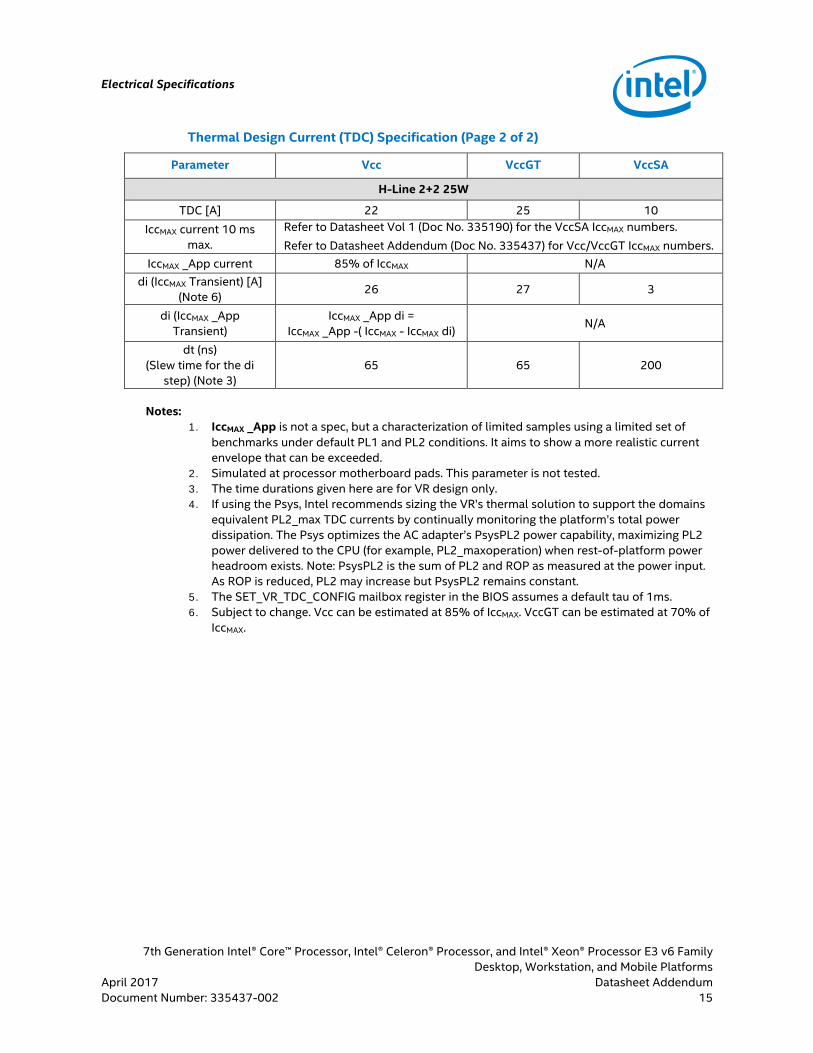
Thermal Design Current (TDC) Specification (Page 2 of 2)
Parameter Vcc VccGT VccSA
H-Line 2+2 25W
TDC [A] 22 25 10 IccMAX current 10 ms
max. Refer to Datasheet Vol 1 (Doc No. 335190) for the VccSA IccMAX numbers. Refer to Datasheet Addendum (Doc No. 335437) for Vcc/VccGT IccMAX numbers.
IccMAX _App current 85% of IccMAX N/A di (IccMAX Transient) [A]
(Note 6) 26 27 3
di (IccMAX _App Transient)
IccMAX _App di = IccMAX _App -( IccMAX - IccMAX di) N/A
dt (ns) (Slew time for the di
step) (Note 3) 65 65 200
Notes:
1. IccMAX _App is not a spec, but a characterization of limited samples using a limited set of benchmarks under default PL1 and PL2 conditions. It aims to show a more realistic current envelope that can be exceeded.
2. Simulated at processor motherboard pads. This parameter is not tested. 3. The time durations given here are for VR design only. 4. If using the Psys, Intel recommends sizing the VR’s thermal solution to support the domains
equivalent PL2_max TDC currents by continually monitoring the platform’s total power dissipation. The Psys optimizes the AC adapter’s PsysPL2 power capability, maximizing PL2 power delivered to the CPU (for example, PL2_maxoperation) when rest-of-platform power headroom exists. Note: PsysPL2 is the sum of PL2 and ROP as measured at the power input. As ROP is reduced, PL2 may increase but PsysPL2 remains constant.
5. The SET_VR_TDC_CONFIG mailbox register in the BIOS assumes a default tau of 1ms. 6. Subject to change. Vcc can be estimated at 85% of IccMAX. VccGT can be estimated at 70% of
IccMAX.

Electrical Specifications
7th Generation Intel® Core™ Processor, Intel® Celeron® Processor, and Intel® Xeon® Processor E3 v6 Family Desktop, Workstation, and Mobile Platforms Datasheet Addendum April 2017 16 Document Number: 335437-002
4.4 H-Line Platform Power Map and Rail Requirements
Figure 2. Processor Platform Power Map - H–Line
Note: For the complete figure, refer to the Kaby Lake Platform Power Architecture Guide. Contact your Intel representative for additional information..
4.4.1 IMVP8 Voltage and Current Requirements - H-Line
Table 8. General Processor VR Parameters for the H-line
Parameter Description Power Rail
H-Line CPU SKU 42/22 Notes
R_DC_LL (mV/A) MAX
Load line slope within the VR regulation loop
capability 0–1 kHz
Vcc 1.8
More information about decoupling recommendations and associated VR bandwidth requirements are shown in the Kaby Lake H Platform Design Guide. Contact your Intel representative for additional information.
VccGT 2.65
VccGTX
VccSA 10
R_AC_LL (mV/A) MAX
Load line slope in response to dynamic load increase events
1 kHz-1 MHz
Vcc 1.8
VccGT 2.65
VccGTX
VccSA 10
Note: For the complete table, refer to the Kaby Lake Platform Power Architecture Guide. Contact your Intel representative for additional information.

Electrical Specifications
7th Generation Intel® Core™ Processor, Intel® Celeron® Processor, and Intel® Xeon® Processor E3 v6 Family Desktop, Workstation, and Mobile Platforms
April 2017 Datasheet Addendum Document Number: 335437-002 17
4.4.2 GT2/3/4 Graphics Frequency
Table 9. GT2/3/4 Graphics Frequency (H -Processor Line)
Segment GT Unslice GT Unslice + 1 GT Slice
GT Unslice + 2 GT Slice
GT Unslice + 3 GT Slice
H – Quad Core GT4/GT3+OPC
GT Max. Dynamic Frequency
[GT Unslice only] - (1 or 2)BIN
[GT Unslice + 1 Slice] - (1or2)BIN
[GT Unslice + 2 Slice] - (1or2)BIN
Note: For more information, refer to Table 2-15 in 7th Generation Intel® Processor Families for H Platforms – Datasheet Volume 1 of 2 (Doc No. 335190).
4.4.3 H-Processor Line Thermal and Power Specifications
Table 10. TDP Specifications (H-Processor Line)
Segment and Package
Processor Intel® Architecture
Cores, Graphics Configuration,
and TDP
Configuration Processor Intel®
Architecture Core Frequency
Graphics Core Frequency
TDP (W)
SDP (W)
H-Processor Line BGA
Quad Core GT4/GT3
35W with OPC
Base 2.5 GHz to TBD GHz 350 MHz to 1.05 GHz 35
N/A LPM 800 MHz 350 MHz 34.5
Quad Core GT4/GT3
45W with OPC
Base 2.3 GHz to 3 GHz 350 MHz
to 1.05 GHz
45
N/A Configurable TDP Down / LFM 1.9 MHz to 2.5 MHz 35
LPM 800 MHz 350 MHz 34.5
Quad Core GT4/GT3
35W with OPC
Base 2.7 GHz 350 GHz to 0.9 GHz 35
N/A LPM 800 MHz 350 MHz 34.5
Note: For more information, refer to Table 5-2 in 7th Generation Intel® Processor Families for H Platforms – Datasheet Volume 1 of 2 (Doc No. 335190).
Table 11. Package Intel® Turbo Boost Technology Specifications (H-Processor Line)
Segment and Package
Processor Intel® Architecture
Cores, Graphics Configuration,
and TDP
Parameter Minimum Hardware Default Maximum Units
H-Processor Line BGA
Quad Core GT4/GT3 45W
with OPC
Power Limit 1 Time (PL1 Tau) Power Limit 1 (PL1) Power Limit 2 (PL2)
0.01 N/A N/A
1 45
1.25*45
448 N/A N/A
s W W
Note: For more information, refer to Table 5-3 in 7th Generation Intel® Processor Families for H Platforms – Datasheet Volume 1 of 2 (Doc No. 335190).

Electrical Specifications
7th Generation Intel® Core™ Processor, Intel® Celeron® Processor, and Intel® Xeon® Processor E3 v6 Family Desktop, Workstation, and Mobile Platforms Datasheet Addendum April 2017 18 Document Number: 335437-002
4.4.4 Processor Power Rails DC Specifications
Table 12. Processor Intel® Architecture Core (Vcc) Active and Idle Mode DC Voltage and Current Specifications
Symbol Parameter Segment Min. Typ. Max. Unit Note1
ICCMAX (H-Processors)
Maximum Processor Intel®
Architecture Core ICC
H (35W) – Quad Core GT4/GT3 + OPC — — 5715
A 4, 6, 7, 11 H (45W) - Quad Core
GT4/GT3 + OPC — — 7415
DC_LL
Load line slope within the VR
regulation loop capability
Y-Processor Line U-Dual Core GT2 U-Dual Core GT3+OPC H-Dual/Quad Core GT2 H-Quad Core GT4/GT3+OPC S-Processor Line
— — — — — —
4.7 — — — — —
5.9 2.4 2.4 1.8 1.6 2.1
mΩ 10, 13, 14
Note: For more information, refer to Table 7-2 in 7th Generation Intel® Processor Families for H Platforms – Datasheet Volume 1 of 2 (Doc No. 335190).
Table 13. Processor Graphics (VccGT and VccGT-X) Supply DC Voltage and Current Specifications
Symbol Parameter Segment Min. Typ. Max. Unit Note1
ICCMAX _GT/ ICCMAX _GTx
(H-Processors)
Maximum Current for Processor Graphics Rail
H (35W) – Quad Core GT4/GT3 + OPC — — 94/20
(GTx)11 A 6
H (45W) – Quad Core GT4/GT3 + OPC — — 94/20
(GTx)11
DC_LL VccGT Load Line Slope
Y-Processor Line U-Dual Core GT2 U-Dual Core GT3+OPC H-Dual/Quad Core GT2 H-Quad Core GT4/GT3+OPC S-Processor Line
— — — — — —
4.2 — — — — —
5.7 3.1
2/6.0 (GTx) 2.65
1.4/6.0 (GTx) 3.1
mΩ 7, 9, 10
Note: For more information, refer to Table 7-3 in 7th Generation Intel® Processor Families for H Platforms – Datasheet Volume 1 of 2 (Doc No. 335190).

Electrical Specifications
7th Generation Intel® Core™ Processor, Intel® Celeron® Processor, and Intel® Xeon® Processor E3 v6 Family Desktop, Workstation, and Mobile Platforms
April 2017 Datasheet Addendum Document Number: 335437-002 19
4.4.5 VccSA DC Specifications
Table 14. System Agent (VccSA) Supply DC Voltage and Current Specifications Symbol Parameter Segment Min. Typ. Max. Unit Note1,2
ICCMAX_VCCSA Max. Current for VccSA Rail
Y-Processor Line U-Dual Core GT2 U-Dual Core GT3+OPC H-Dual/Quad Core GT2 H-Quad Core GT4/GT3+OPC S-Processor Line
— — — — — —
— — — — — —
4.1 4.5 5.1
11.1 8
11.1
A
DC_LL VccSA Load line
Y-Processor Line U-Dual Core GT2 U-Dual Core GT3+OPC H-Dual/Quad Core GT2 H-Quad Core GT4/GT3+OPC
— — — — —
14 — — — —
18 10.3 10.3 10 6
mΩ 6,7
Note: For more information, refer to Table 7-5 in 7th Generation Intel® Processor Families for H Platforms – Datasheet Volume 1 of 2 (Doc No. 335190).
4.4.6 VccPLL DC Specifications
Table 15. Processor PLL_OC (VccPLL_OC) Supply DC Voltage and Current Specifications Symbol Parameter Segment Min. Typ. Max. Unit Note1,2
ICCMAX_VCCPLL_OC
Max. Current for VCCPLL_OC Rail
Y-Processor Line U-Dual Core GT2 U-Dual Core GT3+OPC H-Dual/Quad Core GT2 H-Quad Core GT4/GT3+OPC S-Dual Core GT2 S-Quad Core GT2
— — — — — — —
— — — — — — —
100 100 120 130 150 100 130
mA
Note: For more information, refer to Table 7-10 in 7th Generation Intel® Processor Families for H Platforms – Datasheet Volume 1 of 2 (Doc No. 335190).
4.4.7 Package Mechanical Specifications
Table 16. Package Mechanical Attributes
Package Parameter
Y-Processor Line U-Processor Line H-Processor Line S-Processor Line
Dual Core GT2 Dual Core GT3+OPC
Dual Core GT2
Quad Core GT4/GT3+OPC
Quad Core GT2
Quad Core/ Dual Core GT2
Note: The details for this table, refer to Table 8-1 in 7th Generation Intel® Processor Families for H Platforms – Datasheet Volume 1 of 2 (Doc No. 335190).

Electrical Specifications
7th Generation Intel® Core™ Processor, Intel® Celeron® Processor, and Intel® Xeon® Processor E3 v6 Family Desktop, Workstation, and Mobile Platforms Datasheet Addendum April 2017 20 Document Number: 335437-002
4.5 USB On-The-Go Specification
The embedded 7th generation Intel® Processor for S-Platform SKU does not support USB On-The-Go specification mentioned in the following:
• Intel® 100 Series Chipset Family Platform Controller Hub (PCH) Datasheet – Volume 1 of 2 (Doc No. 332690).
• Kaby Lake S Platform Design Guide. Contact your Intel representative for additional information.
§

Processor Listings
7th Generation Intel® Core™ Processor, Intel® Celeron® Processor, and Intel® Xeon® Processor E3 v6 Family Desktop, Workstation, and Mobile Platforms
April 2017 Datasheet Addendum Document Number: 335437-002 21
5.0 Processor Listings
Table 17. U-Processor Family Listing/Package BGA1356
In Table 17, Turbo refers to Intel® Turbo Boost Technology.
SSPE
C
MM
#
Proc
esso
r N
umbe
r
Step
ping
Cach
e Si
ze (M
B)
Func
tiona
l Cor
e
Inte
grat
ed
Gra
phic
s Co
re S
KU
Max
imum
Tur
bo
Freq
. Rat
e (G
Hz)
Mem
ory
DD
R3L
(MH
z)
Mem
ory
DD
R4 (M
Hz)
Spee
d (G
Hz)
Inte
grat
ed
Gra
phic
s Fr
eque
ncy
(GH
z)
Inte
grat
ed
Gra
phic
s Tu
rbo
Freq
uenc
y (G
Hz)
TDP
Pack
age
SR33Z 953350 i7-7600U H-0 4 2 2 1 Core: 3.9 2 Core: 3.9
1600 2133 2.8 0.30 1.15 15W BGA1356
SR340 953351 i5-7300U H-0 3 2 2 1 Core: 3.5 2 Core: 3.5
1600 2133 2.6 0.30 1.10 15W BGA1356
SR343 953354 i3-7100U H-0 3 2 2 1 Core: 2.4 2 Core: 2.4
1600 2133 2.4 0.30 1.00 15W BGA1356
SR34A 953361 3965U H-0 2 2 1 1 Core: 2.2 2 Core: 2.2
1600 2133 2.2 0.30 0.90 15W BGA1356

Processor Listings
7th Generation Intel® Core™ Processor, Intel® Celeron® Processor, and Intel® Xeon® Processor E3 v6 Family Desktop, Workstation, and Mobile Platforms Datasheet Addendum April 2017 22 Document Number: 335437-002
Table 18. S-Processor Family Listing/Package LGA1151
In Table 18, Turbo refers to Intel® Turbo Boost Technology.
SSPE
C
MM
#
Proc
esso
r N
umbe
r
Exte
rnal
Ste
ppin
g
Cach
e Si
ze (M
B)
Func
tiona
l Cor
e
Inte
grat
ed G
raph
ics
Core
SKU
Max
imum
Tur
bo
Freq
. Rat
e (G
Hz)
Mem
ory
DD
R3L
(MH
z)
Mem
ory
DD
R4 (M
Hz)
Spee
d (G
Hz)
Inte
grat
ed G
raph
ics
Freq
uenc
y (G
Hz)
Inte
grat
ed G
raph
ics
Turb
o Fr
eque
ncy
(GH
z)
TDP
Pack
age
SR32A 952791 E3-1275v6 B-0 8 4 2
1 Core: 4.2 2 Core: 4.1 3 Core: 4.1 4 Core: 4.0
1866 2400 3.8 0.35 1.15 73W LGA1151
SR338 953004 i7-7700 B-0 8 4 2
1 Core: 4.2 2 Core: 4.1 3 Core: 4.1 4 Core: 4.0
1866 2400 3.6 0.35 1.15 65W LGA1151
SR339 953005 i7-7700T B-0 8 4 2
1 Core: 3.8 2 Core: 3.7 3 Core: 3.7 4 Core: 3.6
1866 2400 2.9 0.35 1.15 35W LGA1151
SR335 953001 i5-7500 B-0 6 4 2
1 Core: 3.8 2 Core: 3.7 3 Core: 3.7 4 Core: 3.6
1866 2400 3.4 0.35 1.10 65W LGA1151
SR337 953003 i5-7500T B-0 6 4 2
1 Core: 3.3 2 Core: 3.2 3 Core: 3.2 4 Core: 3.1
1866 2400 2.7 0.35 1.10 35W LGA1151
SR32Z 952995 i3-7101E B-0 3 2 2 1 Core: 3.9 1866 2400 3.9 0.35 1.10 54W LGA1151
SR374 955013 i3-7101TE B-0 3 2 2 1 Core: 3.4 1866 2400 3.4 0.35 1.10 35W LGA1151
SR38G 955177 G3930E B-0 2 2 1 1 Core: 2.9 1600 2133 2.9 0.35 1.05 54W LGA1151
SR38H 955178 G3930TE B-0 2 2 1 1 Core: 2.7 1600 2133 2.7 0.35 1.00 35W LGA1151

Processor Listings
7th Generation Intel® Core™ Processor, Intel® Celeron® Processor, and Intel® Xeon® Processor E3 v6 Family Desktop, Workstation, and Mobile Platforms
April 2017 Datasheet Addendum Document Number: 335437-002 23
Table 19. H-Processor Family Listing/Package BGA1440
In Table 19, Turbo refers to Intel® Turbo Boost Technology.
SSPE
C
MM
#
Proc
esso
r N
umbe
r
Exte
rnal
Ste
ppin
g
Cach
e Si
ze (M
B)
Func
tiona
l Cor
e
Inte
grat
ed G
raph
ics
Core
SKU
Max
imum
Tur
bo
Freq
. Rat
e (G
Hz)
Mem
ory
DD
R4 (M
Hz)
Spee
d (G
Hz)
Inte
grat
ed G
raph
ics
Freq
uenc
y (G
Hz)
Inte
grat
ed G
raph
ics
Turb
o Fr
eque
ncy
(GH
z)
TDP
Pack
age
SR32K 952951 E3-1505Mv6 B-0 8 4 2
1 Core: 4.0 2 Core: 3.8 3 Core: 3.7 4 Core: 3.6
2400 3.0 0.35 1.10 45W BGA1440
SR34X 953947 E3-1505Lv6 B-0 8 4 2
1 Core: 3.0 2 Core: 2.9 3 Core: 2.8 4 Core: 2.7
2400 2.2 0.35 1.00 25W BGA1440
SR3FO 956301 E3-1501Mv6 B-0 6 4 2
1 Core: 3.6 2 Core: 3.5 3 Core: 3.4 4 Core: 3.3
2400 2.9 0.35 1.00 45W BGA1440
SR3EZ 956300 E3-1501Lv6 B-0 6 4 2
1 Core: 2.9 2 Core: 2.8 3 Core: 2.7 4 Core: 2.6
2400 2.1 0.35 1.00 25W BGA1440
SR34S 953940 i7-7820EQ B-0 8 4 2
1 Core: 3.7 2 Core: 3.6 3 Core: 3.5 4 Core: 3.4
2400 3.0 0.35 1.00 45W BGA1440
SR34T 953941 i5-7440EQ B-0 6 4 2
1 Core: 3.6 2 Core: 3.5 3 Core: 3.4 4 Core: 3.3
2400 2.9 0.35 1.00 45W BGA1440
SR34U 953942 i5-7442EQ B-0 6 4 2
1 Core: 2.9 2 Core: 2.8 3 Core: 2.7 4 Core: 2.6
2400 2.1 0.35 1.00 25W BGA1440
SR34V 953943 i3-7100E B-0 3 2 2 1 Core: 2.9 2 Core: 2.9
2400 2.9 0.35 0.95 35W BGA1440
SR34W 953944 i3-7102E B-0 3 2 2 1 Core: 2.1 2 Core: 2.1
2400 2.1 0.35 0.95 25W BGA1440
§