79 Railway Technology Latest Technologies Avalanche August ... · • Servo-cylinder for tilting...
6
Railway Technology Avalanche The Business Promotion Division of Railway Technical Research Institute (RTRI) promotes a wide range of research projects for the government, the Japan Railway Construction, Transport and Technology Agency, railway operators and other organizations. These research projects are significant especially because: (1) the results of RTRI's research and the know-how gained from it benefit society; (2) the research leads to the acquirement of basic information on client needs and technical data that can be used to formulate new research and development goals; and (3) the projects provide economic benefits to RTRI itself. We recently installed within the Business Promotion Division two new sections - one in charge of promoting the maintenance of railway structures, the other in charge of examining railway use. These two new sections will keep communications open between clients such as railway operators and the research units within RTRI. Since the maintenance and management of railway structures is extremely important to railway operators, the section in charge of promoting railway structure maintenance has been equipped to provide them with as much support as possible. As of April 2006, this section has a chief and three staff members. They are meeting with railway operators to discuss what RTRI can do to help them maintain and manage their railway structures. In addition to promoting the maintenance and management of railway structures, the Business Promotion Division is keen to carry out other activities that will be helpful to its many clients. 1 79 ■ Foreword Osamu MURATA ................................................................ 79 ■ A Sample of Products Developed by Railway Technical Research Institute Toshihiro HAMAMOTO ............................................................ 80 ■ A New Algorithm for Train Rescheduling Using Rescheduling Patterns Chikara HIRAI ..................................................................... 81 ■ Evaluation of Train Rescheduling Alternatives Using Station Service Indices Taketoshi KUNIMATSU .............................................................. 82 ■ Development of a New Pantograph Contact Strip for Ultrahigh- Speed Operations Hiroshi TSUCHIYA ................................................ 83 ■ Axle-Box Rotary Shaft Lip Seal for High-Speed Shinkansen Cars Kazuo NAKAMURA .............................................................................. 84 GENERAL INFORMATION ARTICLES August 10, 2006 No. 14 Railway Technical Research Institute 2-8-38 Hikari-cho, Kokubunji-shi Tokyo 185-8540, JAPAN URL: http://www.rtri.or.jp Copyright © 2006 Railway Technical Research Institute. All rights reserved. Reproduction in whole or part without permission is prohibited. Printed in Japan. Newsletter on the Latest Technologies Developed by RTRI Foreword Osamu MURATA Director, Marketing and Business Development Division
Transcript of 79 Railway Technology Latest Technologies Avalanche August ... · • Servo-cylinder for tilting...

RailwayTechnologyAvalanche
The Business Promotion Division of Railway TechnicalResearch Institute (RTRI) promotes a wide range ofresearch projects for the government, the Japan RailwayConstruction, Transport and Technology Agency, railwayoperators and other organizations. These research projectsare significant especially because: (1) the results of RTRI'sresearch and the know-how gained from it benefit society;(2) the research leads to the acquirement of basicinformation on client needs and technical data that can beused to formulate new research and development goals; and(3) the projects provide economic benefits to RTRI itself.We recently installed within the Business PromotionDivision two new sections - one in charge of promoting themaintenance of railway structures, the other in charge ofexamining railway use. These two new sections will keepcommunications open between clients such as railwayoperators and the research units within RTRI. Since themaintenance and management of railway structures isextremely important to railway operators, the section incharge of promoting railway structure maintenance hasbeen equipped to provide them with as much support aspossible. As of April 2006, this section has a chief and threestaff members. They are meeting with railway operators todiscuss what RTRI can do to help them maintain andmanage their railway structures.In addition to promoting the maintenance and managementof railway structures, the Business Promotion Division iskeen to carry out other activities that will be helpful to itsmany clients.
1
79
■ Foreword Osamu MURATA ................................................................ 79■ A Sample of Products Developed by Railway Technical Research
Institute Toshihiro HAMAMOTO ............................................................ 80
■ A New Algorithm for Train Rescheduling Using ReschedulingPatterns Chikara HIRAI ..................................................................... 81
■ Evaluation of Train Rescheduling Alternatives Using Station ServiceIndices Taketoshi KUNIMATSU .............................................................. 82
■ Development of a New Pantograph Contact Strip for Ultrahigh-Speed Operations Hiroshi TSUCHIYA ................................................ 83
■ Axle-Box Rotary Shaft Lip Seal for High-Speed Shinkansen CarsKazuo NAKAMURA .............................................................................. 84
GENERAL INFORMATION
ARTICLES
August 10, 2006 No. 14
Railway Technical Research Institute2-8-38 Hikari-cho, Kokubunji-shiTokyo 185-8540, JAPAN
URL: http://www.rtri.or.jp
Copyright © 2006 Railway Technical Research Institute. All rights reserved.Reproduction in whole or part without permission isprohibited. Printed in Japan.
Newsletter on theLatest TechnologiesDeveloped by RTRI
Foreword
Osamu MURATADirector, Marketing and Business Development Division

2
80 Railway Technology Avalanche No. 14, August 10, 2006
Railway Technical Research Institute (RTRI) conducts testsand research for companies and other organizations, usingknow-how that it has accumulated through its extensiveR&D activities. In this way, RTRI responds to diverseneeds of the railway industry and the traveling public, bothat home and abroad.The many and varied R&D projects commissioned to RTRIinclude testing, studies, design and engineering. We alsooffer lectures and advice on a wide range of rail technologyissues.Ten major products developed by RTRI are outlined below.
1. Products for vehicles• Cerajet (an adhesion improvement material jetting device):
This device is used to improve the adhesion coefficient byjetting ceramic or silica sand particles between the wheel andthe rail. Because of the high jet speed and good response, thedevice can be interlocked with slide/slip signals andemergency brake commands. It can be used during both lowand high speed operations (Fig. 1).
• Servo-cylinder for tilting car: This compact device combinesa cylinder, servo-valve and displacement sensor. It controlsthe tilt of a tilting car.
• Semi-active suspension system for railway vehicles: Thissystem significantly reduces lateral vibrations of a carbodyabove the bogie springs, making it possible to increaserunning speed and improve riding comfort.
• Simple vibration and riding comfort measurement device:This compact, low-cost system measures vehicle vibrations
easily, even duringcommercial runs.Simple softwarefor analyzingvehicle vibrationand riding comfortlevels has alsobeen developedfor the device.
2. Products for signal, communication and electricsystems
• Computer and Microwave Balise-Aided Train control system(COMBAT): This system detects a train with a non-contact,point-detection method using microwaves. It is equal orsuperior to conventional track circuitry in terms of safety anddetection performance (Fig. 2).
• Catenaries/pantograph system motion simulator: Thissimulator facilitates complicated calculations to accuratelyanalyze the design and deformation of overhead contact wirestructure, the motion of catenary/pantograph systems, etc.,using a personal computer.
• POWER DIAGRAM: This simulator permits ascertaining theever-changing load factors of each train in an operatingschedule within an entire track section. It can be used tocalculate suitable substation capacity, pantograph pointvoltage, etc.
3. Products for infrastructure• Ladder track: This ladder-shaped track system is composed of
a pair of rails on longitudinal pretension concrete beams thatare fastened together with lateral steel pipes. We havedeveloped two types of ladder tracks: a ballasted ladder trackfor track laid on ballast, and a floating ladder track for tracknot laid on ballast (Fig. 3).
• Micro LABOCS (track maintenance and managementdatabase system): The database contains track inspectiondata, measurement data obtained during train operations,track diagrams, etc. The data can be analyzed and processedas needed.
• IMPACT-III (bridge substructure soundness evaluationsystem): RTRI has established an impact and vibration testmethod to accurately determine the soundness of bridgesubstructures and elevated bridges. Our bridge substructuresoundness evaluation system "IMPACT" effectively supportstest functions. IMPACT-III is the latest IMPACT edition.
A Sample of Products Developed by Railway Technical Research InstituteToshihiro HAMAMOTOGeneral Manager, Market Planning, Marketing and Business Development Division
Adhesion improvementmaterial tank
Nozzle
Figure 1. Installation of Cerajet
Onboard responder
Ground responder Interrogator
Figure 2. COMBAT Figure 3. Floating ladder track
3
Railway Technology Avalanche No. 14, August 10, 2006 81
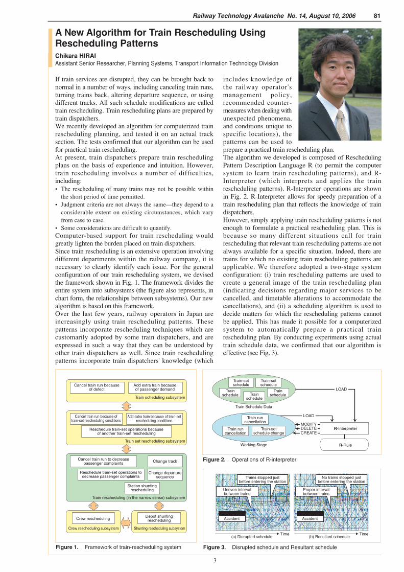
If train services are disrupted, they can be brought back tonormal in a number of ways, including canceling train runs,turning trains back, altering departure sequence, or usingdifferent tracks. All such schedule modifications are calledtrain rescheduling. Train rescheduling plans are prepared bytrain dispatchers.We recently developed an algorithm for computerized trainrescheduling planning, and tested it on an actual tracksection. The tests confirmed that our algorithm can be usedfor practical train rescheduling.At present, train dispatchers prepare train reschedulingplans on the basis of experience and intuition. However,train rescheduling involves a number of difficulties,including:• The rescheduling of many trains may not be possible within
the short period of time permitted.• Judgment criteria are not always the same—they depend to a
considerable extent on existing circumstances, which varyfrom case to case.
• Some considerations are difficult to quantify.Computer-based support for train rescheduling wouldgreatly lighten the burden placed on train dispatchers.Since train rescheduling is an extensive operation involvingdifferent departments within the railway company, it isnecessary to clearly identify each issue. For the generalconfiguration of our train rescheduling system, we devisedthe framework shown in Fig. 1. The framework divides theentire system into subsystems (the figure also represents, inchart form, the relationships between subsystems). Our newalgorithm is based on this framework.Over the last few years, railway operators in Japan areincreasingly using train rescheduling patterns. Thesepatterns incorporate rescheduling techniques which arecustomarily adopted by some train dispatchers, and areexpressed in such a way that they can be understood byother train dispatchers as well. Since train reschedulingpatterns incorporate train dispatchers' knowledge (which
includes knowledge ofthe railway operator'smanagement policy,recommended counter-measures when dealing withunexpected phenomena,and conditions unique tospecific locations), thepatterns can be used toprepare a practical train rescheduling plan.The algorithm we developed is composed of ReschedulingPattern Description Language R (to permit the computersystem to learn train rescheduling patterns), and R-Interpreter (which interprets and applies the trainrescheduling patterns). R-Interpreter operations are shownin Fig. 2. R-Interpreter allows for speedy preparation of atrain rescheduling plan that reflects the knowledge of traindispatchers.However, simply applying train rescheduling patterns is notenough to formulate a practical rescheduling plan. This isbecause so many different situations call for trainrescheduling that relevant train rescheduling patterns are notalways available for a specific situation. Indeed, there aretrains for which no existing train rescheduling patterns areapplicable. We therefore adopted a two-stage systemconfiguration: (i) train rescheduling patterns are used tocreate a general image of the train rescheduling plan(indicating decisions regarding major services to becancelled, and timetable alterations to accommodate thecancellations), and (ii) a scheduling algorithm is used todecide matters for which the rescheduling patterns cannotbe applied. This has made it possible for a computerizedsystem to automatically prepare a practical trainrescheduling plan. By conducting experiments using actualtrain schedule data, we confirmed that our algorithm iseffective (see Fig. 3).
A New Algorithm for Train Rescheduling UsingRescheduling PatternsChikara HIRAIAssistant Senior Researcher, Planning Systems, Transport Information Technology Division
Figure 1. Framework of train-rescheduling system
Cancel train run becauseof defect
Add extra train becauseof passenger demand
Cancel train run because oftrain-set rescheduling conditions
Add extra train because of train-setrescheduling conditions
Reschedule train-set operations becauseof another train-set rescheduling
Cancel train run to decreasepassenger complaints
Reschedule train-set operations todecrease passenger complaints
Station shuntingrescheduling
Change track
Crew rescheduling Depot shuntingrescheduling
Change departuresequence
Train scheduling subsystem
Train set rescheduling subsystem
Train rescheduling (in the narrow sense) subsystem
Shunting rescheduling subsystemCrew rescheduling subsystem
Train-setschedule
Train-setschedule
Trainschedule Train
schedule
Trainschedule
Train runcancellation
Train runcancellation
Train-setschedule change
Train Schedule Data
R-Interpreter
R-RuleWorking Stage
LOAD
LOAD
MODIFYDELETECREATE
Figure 2. Operations of R-interpreter
Accident
Time
Accident
Time
Uneven intervalbetween trains
(a) Disrupted schedule (b) Resultant schedule
Trains stopped justbefore entering the station
Proper intervalbetween trains
No trains stopped justbefore entering the station
Figure 3. Disrupted schedule and Resultant schedule

4
82 Railway Technology Avalanche No. 14, August 10, 2006
Figure 1. Track layout of affected section
Segment closed totraffic (inside track)
ExpressA
B
C
D
E
F
G
RapidRapid (with track change)Local
Figure 2. Train Rescheduling Plan X (plan actuallyimplemented, with track change)
55
50
45
40
35
30
30000
24000
18000
12000
6000
0A
Sta
tion
serv
ice
indi
ces
Num
ber
of d
epar
ting
pass
enge
rs
B C D E F G Station
Rescheduling Plan X, with track change (left scale)Rescheduling Alternative Y, without track change (left scale)Number of passengers departing from station (right scale)
Figure 4. Calculated station service indices
During the disruption of train services, a series of timetablealterations must be made to return services to normal. Thisseries of corrective actions is called train rescheduling. Toevaluate train rescheduling alternatives, a number of indiceshave been proposed, such as the total time of train delays,and the number of trains canceled. However, such indicesdeal only with matters from an overall operationalstandpoint, and do not reflect the standpoint of individualpassengers suffering the inconvenience of the servicedisruption. In addition, evaluation results cannot beunderstood instantly.This paper proposes the use of individual station serviceindices to evaluate train rescheduling alternatives. Eachstation service index expresses, in terms of actual travelspeed, the extent of service that passengers departing fromthe station can receive on average, under a specificrescheduling timetable. When determining these individualstation service indices, we added a component reflectingpassenger dissatisfaction with the increase in congestion.Individual station service indices are calculated as follows.(1) Using the train rescheduling timetable and automaticticket inspection machine data, infer the trains that eachpassenger takes from their departure station toward theirintended arrival station, then calculate the actual timerequired for their travel, including wait time.(2) From the data on the number of passengers in each train,estimate each passenger's dissatisfaction quotient withregard to crowded conditions, and expressed this quotientas time. Add this time to the actual time required for travel.(3) Divide the distance from the departure station to theintended arrival station by the sum of (1) and (2), to obtainthe effective speed (perceptible travel speed) for eachpassenger.(4) Calculate the average effective speeds for each of thedeparture stations and assume it as the station service indexfor that departure station.Using these station service indices, we evaluated an actualtrain rescheduling plan (Rescheduling Plan X, Fig. 2) thatwas implemented in a quadruple-track section (track layoutshown in Fig. 1), and an operations rescheduling alternative(Rescheduling Alternative Y, Fig. 3) that was based on a
different concept. Thetrain rescheduling wasrequired after a trafficaccident involving injuryoccurred at Station D,forcing the operation of upand down trains on theinside tracks to stop forabout 30 minutes, beginning at 5:26 p.m. In this section,express trains normally run on the outside tracks, whilerapid and local trains run on the inside tracks. UnderRescheduling Plan X, the route for rapid trains indicated bythe brown lines in Fig. 2 was changed from the inside to theoutside track. Rapid trains ordinarily stop at Station C.However, in Rescheduling Plan X, rapid trains do not stopat the station because the station has no platform for theoutside tracks. On the other hand, under ReschedulingAlternative Y, rapid trains continue running on the insidetracks, with no change in track. In this case, rapid trainscould stop at Station C, but the problem of a delay of therapid train arises. The calculated station service indices forthese two cases are shown in Fig. 4.Under Rescheduling Plan X, the station service index forStation F, where express trains do not stop, is higher thanunder Rescheduling Alternative Y. On the other hand,station service indices at stations A and B are higher underRescheduling Alternative Y than under Rescheduling PlanX. This is because with Rescheduling Alternative Y,although two up rapid trains would be forced to stop atStation F for a long time, express trains running on theoutside tracks would not be delayed. Thus, use of stationservice indices makes it possible to easily ascertain theconvenience quotient of passengers departing from eachstation.Our future tasks with regard to station service indicesinclude considering passenger dissatisfaction levels formatters other than the longer travel time and greatervehicular congestion (e.g., their need for extra transfers),and improving the accuracy of models representingpassenger behavior during service disruption.
Evaluation of Train Rescheduling Alternatives UsingStation Service IndicesTaketoshi KUNIMATSUResearcher, Planning Systems, Transport Information Technology Division
Express
Outside track (Express)
Outside track (Express)
Inside track (Rapid and Local)
Inside track (Rapid and Local)
Express
Rapid
Local
Rapid
Local
Stations
GFEDCBA
Track changefor rapid trains Accident site
(Station D)
Segment closed totraffic (inside track)
ExpressA
B
C
D
E
F
G
RapidLocal
Figure 3. Train Rescheduling Alternative Y (modified plan,without track change)

5
Railway Technology Avalanche No. 14, August 10, 2006 83
Development of a New Pantograph Contact Strip for Ultrahigh-SpeedOperationsHiroshi TSUCHIYASenior Researcher, Frictional Materials, Materials Technology Division
With Shinkansen trains traveling at even higher speeds, it isexpected that wear rates of pantograph contact strip willincrease significantly, because of such factors as thestronger collecting current and the greater number of arcdischarge generated during contact loss. Any developmentof a new contact strip material for effective use at anultrahigh-speed (speeds above 300 km/h) would have toachieve better heat resistance and lubricating capability byimproving iron-based sintered alloy which is used in highspeed trains.Our objective is to develop a new contact strip materialoffering more effective performance at ultrahigh-speed.Wear characteristics of a new contact strip material whichcontains tungsten were compared with those of theunleaded sintered alloy contact strip that had already beendeveloped. A high-speed wear tester for current-collectingmaterials, which permits evaluation of wear behavior undersimulated ultrahigh-speed conditions (exceeding 300km/h), was used to evaluate the wear characteristics of eachcontact strip material.By conducting sliding wear tests at a speed of 400 km/h,using the high-speed wear tester for current-collectingmaterials (see Fig. 1) under electric current, it wasconfirmed that the addition of a tungsten-based material asa hard, heat-resistant metallic component improved arcdischarge resistance significantly, and made it possible toachieve wear resistance superior to that of a conventionalmaterial (see Fig. 2).The developing material is higher in density than that ofconventional material because tungsten is heavy, so thepantograph incorporating the developing material would beheavier than one with a conventional material. In addition, acontact strip incorporating the developing material wouldcost more, because tungsten is expensive. We are planning
to develop better contact strip materials which containoptimal tungsten volume to maintain the excellent wearcharacteristics, and reduce the cost and the weight.
Simulated trolley wire
Diameter: 2 m
Contact strip test piecesRevolving disk
Principal test conditions
(1) Speeds: 300 km/h, 400 km/h
(2) Current: 50 A/strip
(3) Contact loss rate:Approx. 30% to 70% (measured by voltage drop)
(4) Applied force:49N
Figure 2. Comparison of wear resistance at 400 km/h
10
8
6
4
2
0
Wea
r ra
te
mm
3 /km
Conventionalunleaded material
Developingmaterial
Figure 1. High-speed wear tester for current-collecting materials, and principal test conditions

6
84 Railway Technology Avalanche No. 14, August 10, 2006
When the speed of Shinkansen cars is increased to a rangeof 350-400 km/h, there is a concern that oil leakage fromthe axle-box rotary shaft lip seal could increase to the extentthat it would be difficult to ensure normal lubricatingconditions for the axle bearings, because the higher shaftrotational speeds make sliding conditions severe. Wetherefore developed a new axle-box rotary shaft lip seal forhigh-speed Shinkansen cars with the ability to withstandexceptionally severe sliding conditions.The results of bench tests of axle-box rotary shaft lip sealsare shown in Fig. 1. Conventional seals 1 and 2 bothshowed oil drips under high-speed conditions, indicatingthat neither is suitable for high-speed Shinkansen cars (seeFig. 1 (a)). An examination of the seals and oil throwersafter the tests showed that lip radial loads were normal, andhardness measurements indicated that the degree of rubberdeterioration was small. The amount of wear on the parts ofthe oil throwers in contact with the lip was also negligible.However, an observation of the lip contact surface of eachof the conventional seals revealed outbreaks of flaking onalmost the entire circumference (see Fig. 1 (b)). Inparticular, the outbreaks of flaking on the two conventionalseals were more conspicuous under high-speed conditionsthan under current speed conditions. The outbreaks offlaking of conventional seal 1 were more conspicuous thanthose of conventional seal 2. It was considered that thoseoutbreaks of flaking were caused by an increase in shearforce and contact surface pressure, due chiefly to increasesin slip speed and pressure changes. From these facts, it wasdetermined that the oil leakage under high-speed conditionswas largely due to the outbreaks of flaking.Therefore, for the new lip seal for high-speed Shinkansen
cars, we adoptedf l u o r o e l a s t o m e r ,which is superior toacrylic rubber interms of durabilityand physical strength.We also changed therubber material fillerto restrain early-stageoutbreaks of flakingcaused by an increase in shaft rotational speed.Furthermore, in order to restrict any change in lip positioncaused by pressure changes that occur, for example, whenthe train passes through a tunnel, the rigidity was improvedby changing the size and shape. A photo of the test-manufactured lip seal is shown in Fig. 2, and its crosssection is shown in Fig. 3.Our test-manufactured lip seal maintained the originalsealing performance with no oil oozing even after the shaftwas turned with the number of rotations equivalent to avehicle running distance of 750,000 km (see Fig. 1 (a)). Anexamination of the lip seal and oil thrower after the testsshowed no problem with the lip radial load, the rubberhardness or the oil thrower. An observation of the lipcontact surface showed that the surface condition wassatisfactory with few outbreaks of flaking (see Fig. 1 (b)).From these results, it was confirmed that our test-manufactured lip seal has sufficient durability even underhigh-speed conditions. Because of its satisfactoryperformance, we consider it suitable as an axle-box rotaryshaft lip seal for high-speed Shinkansen cars.
Axle-Box Rotary Shaft Lip Seal for High-SpeedShinkansen CarsKazuo NAKAMURASenior Researcher, Lubricating Materials, Materials Technology Division
100mm
Figure 2. Test-manufactured lip seal
0 10 20 30 40
Equivalent vehicle running distance (×104km)
(a) Durability
(b) Lip contact surfaces after tests
Conventional seal 1Test-manufactured lip seal Conventional seal 2
Equivalent to avehicle running
distance of 310,000 km
Equivalent to avehicle running
distance of 750,000 km
Equivalent to avehicle running
distance of 600,000 km
Test conditions
No oozing of oil
* Pressure was applied to the sealing side periodically.
Slight oozing of oil
Small amount of oil dripping
High-speed conditions
Current speed conditions
High-speedconditions
Currentspeed
conditions
Rotational speed
2700min-1
(equivalent to 400 km/h)1890min-1
(equivalent to 280 km/h)
Maximum pressure(pressure change)*
0.022MPa
0.011MPa
50 60 70 80
Smooth surface, satisfactory condition Outbreaks of flaking observed
Test-manufactured lip seal: Fluoroelastomer
Conventional seal 1: Acrylic rubber
Conventional seal 2: Fluoroelastomer
Test-manufactured lip seal
Conventional seal 1
Conventional seal 2
Test discontinued due to increase in leakage.
Conventional seal 1
Conventional seal 2
Figure 1. Results of bench tests of axle-box rotary shaft lip seals
Test-manufacturedlip seal
Lip contactsurface
More rigidthan conventional
seals
Garter spring
Metal insert
Axle
Oil thrower
Lubricating oil
Rear cover
Figure 3. Cross section of test-manufacturedlip seal