
79 092 OF CONTENTS Page No. Introduction 1 Empirical Models 1 Analytical Interior Ballistics Models...
39
AD-E4Ofl 337 TECHNICAL REPORT ARSCD-YR-79001 INTERIOR BALLSTICS MODELING APPLIED TO " SMALL ARMS SYSTEMS 41 USARMYSIDNEY GOLDSTEIN WEAPON SYSTEMS LABORATORY DOVER, NEW JERSEY APPROVED FOR PUBLIC RELEASE, DISTRIBUTION UNLIMITED. 79 092 008r,
Transcript of 79 092 OF CONTENTS Page No. Introduction 1 Empirical Models 1 Analytical Interior Ballistics Models...

AD-E4Ofl 337
TECHNICAL REPORT ARSCD-YR-79001
INTERIOR BALLSTICS MODELING APPLIED TO "
SMALL ARMS SYSTEMS
41 USARMYSIDNEY GOLDSTEIN
WEAPON SYSTEMS LABORATORYDOVER, NEW JERSEY
APPROVED FOR PUBLIC RELEASE, DISTRIBUTION UNLIMITED.
79 092 008r,

inthisreor are those of th uhr(s) and
sholdnotbeconstrued masnofca Depart-
men oftheArmy po.ition, policy or decisfon,unlm s deigntedby other donumentation.
Desro tia eprtwhen no longer needed. Do
no eunt h rgntr

UNCLASSIFIED519CUI. '.1111tICATI0N OP TH4IS PAGE (When. Da,0 KnOW0
REPORT DOCUMENTATION PAG9E WOECMLEIGFR1.-RPOR l. iOVT ACCESSION NO. S. RECIPIENT'S CATALOG NUMBER
jechicalReSC RSCDTR-79001TS. TYPE Of REPORT A, PERIOD COVERED
ftei ar .listics Modeling App~ied to Small
S.U4O( -OTRC ORGATNUS-
Z Sidne / ldstein
S. PERFORMING ORGANIZATION NAME AND ADDRESS tO. PROGRAWM ELEMENT, PROJECT, TASKARtEA & WORK UNIT NHiMEERSCommander, ARRADCOI4
sz C&SCWSL, DRDAR-SCA-TADRS
Commander, ARRADCOM jn 7STINFO, DRDAR-TSSDover, NJ 07801 3
RN-TIMINQ .GIENCY NAME IAODRESS(U different 11cm Contbolingd Off#*) IS. SECURITY CLASS. (of thi. report)
Unclassified1S0. OECL ASSI PICATIONIDOWNGRADING
.. .. SCH EDULE
Approved for public release; distribution unlimited.
17. OISTRIOUTION STATEMENT ('of the ab.Utet arniseed in &took it different from Reorti
MS3CD-11_49gg
IS. SUPPLE"-ENTARY NOTES
III. KEY WORDS (Continuean misv~es sideit necesary and 4dMntil by blc nuPessreeave
Interior ballistics Small arms Fracturability'Ballistics modeling Ball propellant Pressure gradient
Empirical model Temperature~ sensitivity Budr aePropellant deterrent technology Blank ammunition Gas transmission
21L ASI7NA CT (CamM. 0 m..waw Ob it bmmW f dsewifj by bleak memnber)
SThe empirical models currently used in the design of small arms interiorballistics systems are reviewed. The development of propellant dpeterrenttechnology and closed bomb burning-rate techniques is discussed. Propellantgrain size distribution and aversjing techniques, temperature sensitivity, andenergy~ losses are also covered. The cur-zent use of two-phase, nonsteady flowmethods to desciibe interior ballistiC3 Systems is reviewed. It is concludedthat each of the models performs a different taskd ithprerdsgn oweapon system.:1
DD 103Avtslolo~~os~T UNCLASSIFIFDA ~ >A:SECURITY C AS5tPICATIOIR 111 THIS PAGE (Nh. Dots 8n'-,.d)
1ý#1

1111CURIfT-GLAFTy04 or eaa... bele ab
SECRIT CLAPAGEIHO HS AEhnDaeft,4

TABLE OF CONTENTS
Page No.
Introduction 1
Empirical Models 1
Analytical Interior Ballistics Models 6
Propellant Deterrent l echnology 6t Analysis
Assumption No. 1 8Assumption No. 2 10Assumption No. 3 10SAssumption No. 4 10
Specialized Interior Ballistics Models 14
Special Aspects of Small Arms Interior Ballistics 16
Gas Transmission Systems 16Pressure Waves 17
I Conclusions and Recommendations 20
References 25
i i Distribution List 33
TABLES
I Interior ballistics equations 9
2 Comparison of approaches 15
ACCESSION forD D CNTIS White SeotloutVDOC Buff Section n
f7 on PUNANNOUNCED L)JUSTI; ICATION
DISTRlBUTIOB/AVAILAIUT CBS
is ,AL. and/ -or SPEC
W-d
FIGURES
Page No.
Velocity at Um/Uo S and Pm 60 kpsi
as a function of C/W 2
2 Relative velocity normalized to unity at anexpansion ratio of S as a function of expansionratio 3
3 Velocity relative to the velocity at a peakpressure of 60 kpsi as a function of peakpressure 4
4 Geometry of rolled ball grain 11
5 Pressure-time records obtained under standardconditions 18
6 The 7.62-mm I.D. vented chamber 19
7 Pressure-time records in test barrel 21
8 Pressure-time-position within barrel 22
9 Position-time of shock waves 23
•II

INTRODUCTION
Significant progress has been made in recent years in modelingthe interior ballistics of small arms weapons systems. In the past,
"K_ small caliber ammunition designers resorted to empirical methods(ref. 1) based on experimental data (ref. 2) to design propellingcharges. However, with the vast amount of research done on deterredsmall arms propellants, enough information has now been obtained tosuccessfully model the burning of these propellants and the interiorballistics in a variety of small caliber weapon systems.
EMPIRICAL MODELS
The most successful empirical small arms interior ballisticsmodel was probably developed by H. P. Manning at Frankford Arsenal(ref. 2). This model comprises a series of curves on experimentsby which selected optimum ballistic parameters of propellant weight(C), projectile weight (W), maximum pressure (P), and expansion ratio IUm/Uo are related. From these sets of curves, the ballistic performanceof many small arms systems can be calculated. The velocity of a systemwith given values of C/W, P, and UM/Uo can be obtained by using theequation:
v.~. V )(Vwhere V5, *6 is the velocity at that ratio of C/W obtained at an ex-pansion ratio of Um/Uo = 5 and peak pressure of P = 60,000 psi j(413.7 MPa); Vx/V& is the relative velocity normalIzed to unity at anI expansion ratio of 5, and Vm/Vso is the velocity relative to thevelocity at a peak pressure of 60 kpsi (figs. 1-3). The Manning
"I curves work well for both IMR and ball propellant within the range ofC/W, Urn/U, and Pm shown in figures 1 through 3. For example:
Given the following data for .30 caliber ball cartridge M2,
Projectile weight 150 grains (9.72 x I0-3 kg)Propellant weight 49.9 grains (3.23 x l0" kg)Bore area 0.0732 in.' (4.72 x 10" mi)Case volume 0.25 A (4.10 x lO-Sm3)Bullet travel 21.9 in. (.556 x m)Maximum pressure 51.2 kpsi (353 MPa)
"I ...J • : , .. ' " .... ... . ... .................

A J1
TT: 44I T F I t I 1 -
-Ft:
IIZ2

Tit t i CIS
Cu 4
~ hull d ~i~h Il Jill lH.i-IT K~~i
IN l II i M IM 't~ 11 It Hl ti il IiU 0
JIM) I 1t 11 : illL ~~,. ii.J
Mill- jl' j 04J
I ILI 1 IN
_ 0 0 0 C
MIN lit 3
Li __
III Ir Ali-
WHI .:"rII
IMI
I V M! J Lit: 1*
P. ,MR V, Li.1H.HI1 *10~ R'j~~. M4 A jin H w hNa itIt
NIB ~ ~ ~ a1 N. N4
WN1.
y) t4141 4t!:".-. H-, F Ut -.-i HP ýF

calculate the muzzle velocity as follows:
C 49.9 o;•' - • - 0.333
{v " zs -
S~where: 2610 is read from figure I1 1.106 is read from figure 2 andL : 0.981 is read i'rom figure 3. For comparison, themuzevlctwaacualyrecorded as 2832 ft/sec (863 m/s).
I S
SDickey (ref. 3) has programmned these curves for use on a computer:
V 0.073213 ]xoge C/2. + 4120
O..668 0.2S
V5 V6 tsc 83ms
,1•= . 4 1 P. weeP has units of kcpsi
wh oyear s (read from foreu1, another empirecal model from his
" many yead o m figur e 3. For caliber weapons. He also refer-ences several other such models that have evolved over the years (ref. 5).
D k As has been previously mentioned, empirical curves apply to.. ,ystefls which use selected optimum ballistic parameters. To obtain-informiVtion about systems with parameters (i.e., C/W, +_, or O /U )
V m*
I • outside of normal limits or to obtain more detailed information~ a~out•:: system characteristics, one must use t~ore sophisticated analyticalinterior ballistics models.
VI>0
V5m 1"1
0.4 hrePhsuit fks
V4 a- -le (r--f. 4)hsfomltd--te-eprca- oe fo i
ANALYTICAL INTERIOR BALLISTICS MODELS
Propellant Deterrent Technology
Propellant with uniform chemical composition is used in largecaliber ammunition. Conversely, small arms weapons generally operateat higher loading densities and pressures and shorter ballistic cycletimes, requiring tVe use of deterred propellants. Deterrents areapplied to the surface of the propellant and diffuse into the grain.They reduce the energy content of the gases and slows the burning rateduring the initial burning phase. This leads to a more progressive
type of burning. Progressivity in large caliber ammunition isnormally achieved by the geometric design of the grain. However,because of the higher loading densities required, progressivity canbe better achieved in small arms by use of deterrent. Although thedeterrent content is only a small percentage of the propellant grain(i.e., 2 to 10%), the surface of the propellant contains a consider-ably higher concentration.
The advance in small arms propellant deterrent technology (ref. 6)has permitted better understanding of and simulation of small caliberinterior ballistics systems. This technology has evolved through theapplication of such investigative techniques as microtoming followedby chemical and microscopic examination to establish the rature ofthe composition gradient (refs. 7-10).
Also, additional investigations involve the use of infraredspectroscopy (ref. 11) and autoradiography (refs. 12-13) to determinecomposition gradients. Much information has been obtained through theuse of closed bombs, Stiefel and Davis (ref. 14) obtained apparentburning rates of small arms propellants from closed bomb data andsuggest the Serebryakov (ref. 15) method for establishing the deter-rent gradient.
The most successful use of closed bombs for obtaining burningrate data on deterred small arms propellants was probably achievedby Riefler and Lowery (ref. 16). They used specially prepared pro-pellant samples of various homogeneous compositions in a closed bomb.Data from the ignition and burnout phase are neglected so that theempirical constants during the complete burning phase alone are cal-culated. Using statistical techniques, they obtain the burning ratecoefficient and exponent for the burning rate equation of the formR = APn. These factors are described in terms of the percentage ofdeterrent (DBP) and the percentage ol nitroglycerin (NG) and poly-nominals involving web size.
6
_7-------- .. --
,• ~~~.. . ..... .. . .. . . . . . ............ ..... .••-•, .. •-•,• ! ',- "
In the development of small arms ammunition, two terms, relativeforce and relative quickness, are used to describe propellants on thebasis of their closed bomb performance. Relative force is the ratioof the force or impetus of a test propellant to the force of a standardpropellant, measured at the same initial temperature and loading densityin the same closed chamber. Relative quickness is defined as the timerate-of-change of pressure (dp/dt) of a test propellant to that of astandard propellant measured at the same initial temperature and load-ing density in the same closed chamber1 .
Analytical models of deterrent concentrations and thermochemicalchayacteristics have been formulated for interior ballistics models.Trafton (ref. 17) simulates the variation of surface deterrent con-centration with depth by assuming that the surface deterrent concen-!:ation is nuzsiderably larger than the average measured value of thetotal grain and that it then decreases linearly (with grain volumeburned) to a value of zero at some depth in the grain. To computethe penetration depth of the deterrent, he assumes that the deterrentdoes not change the propellant density and that the changes in deterrentconcentration occur between equal volume increments of the grain. Hehas further modified (ref. 18) his model to include a stepwise con-centration to a given depth.
Gottlieb (ref. 19) et al, have conducted 'both analytical and•
experimental studies on the effective progressivity of deterredpropellants. They have been able to simulate P vs P traces of both J
adiabatic and nonadiabatic closed vessel firings. To accomplish thisa system of differential equations by which pressure, fraction of webburned, amount of gas generated, system temperature, and wall tem-perature are related as functions of time was formulated and solved tosimulate closed chamber firings.
In the United States today, the ball propellant used in almostall small arms ammunition is manufactured by a solvent emulsion pro-cess that results in bulk mixtures of va, -ying grain sizes and differentchemical compositions (i.e., different levels of deterrent) for dif-ferent sieve sizes. Trafton assumes the deterrent content variesinversely with grain size. Thus with this model, one can take intoaccount both the effect of different grain size distribution on gasproduction and the effect of different grain size on the chemicalcomposit-ion.
'Olin Corporation uses WC 846, which is the propellant for 7.62 mm,as a reference propellant. E.I. DuPont de Nemours Co. uses IMR4350 as a standard.
7

Trafton also uses a separate thermochemical computer model tocalculate impetus and flame temperatures for the varied chemicalcompositions that include the rssumed deterrent concentrations com-bined with the base propellant. Also, with his model, one is able totreat nonsimultaneous ignition of the propellant charge by use of thesimplified assumption that the total surface of the propellant grainignites smoothly at a uniform rate from the primer end of the chargeforward as a function of time. This effect can be important in simu-lating small arms interior ballistics.
Analysis
The interior ballistic equations used by Trafton were modifiedfrom those of Baer and Frankle (ref. 20) to include the effects ofdeterrent coating and nonsimultaneous ignition. These equations areshown in table 1 and include:
1. Energy equation.
2. Equation of state.
3. Mass fraction burn rate equations.
4. Equations of projectile motion.
Goldstein (ref. 21) has modified Trafton's program to accept asimplified model describing the thermochemical properties and burningrate of deterred rolled ball propellant. His model includes thefollowing:
Assumption No. 1
Each grain in the charge is of uniform geometry and hasdimensions determined by the equivalent mean radius R obtained fromthe sieve size distribution of the propellant lot. This dimensionis given by:
3 FiVi]
Fi/Voi
where Ri = average radius of a propellant grain from a given sievecut (ref. 22).
Voi = initial volume of propellant grain of radius Ri.Fi = fraction of charge weight or volume with radius Ri.
L .8
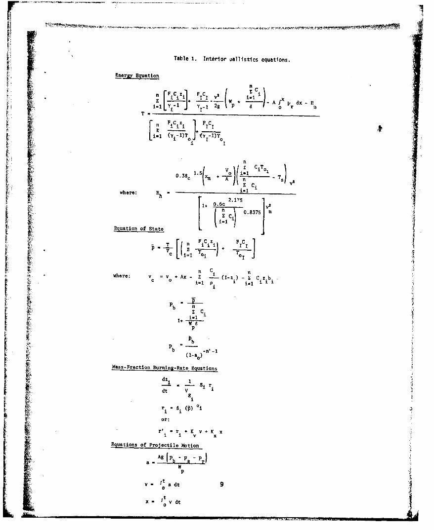
Table 1. Interior uallistics equations.
Energy Equation
'9 n
II IC V
T C
Equatio of Stt
V n C nCC 0
i=1 01
r 6where: p
EqassFation ofnngRt Stuaioe
dt Tc B 1 TO)
where v v Ax Z x
p
i.14

This method of defining R has %o7-, used previously when one con-siders heat and mass transfer and reacti-.n at the fluid particlesurface interface (ref. 23). Kitchens, (r.A. 24) in treating flamespreading through a propellant bed, used mean diameters discussed byZabrodsky (ref. 25). They are described by the equations
1 Xl X2 XnTA dT1 d2 dn
ord = Xldl + X2d2 + .... ÷ XndnB
where X1 is the weight fraction of a narrow fraction of diameter dl.Subscripts A and B are used to represent the two different methods ofdetermining the mean diameter. Smith (ref. 26) assumes that thecharacteristic grain dimension (i.e., diameter) is distributed normallyabout a mean value.
Assumption No. 2
The penetration of the propellant grain by the deterrentfollows Levy's findings that the migration of modifiers into ballpropellant can be characterized by a diffusion front exhibiting highconcentration gradients that result in sharp lines of demarcationbetween various layers. This is in accordance with normal plasticizer-polymer difus 4 on systems. Smith assumes that the deterrent diffusesin a manner similar to conduction of heat in a semi-infinite solid.Since the penetration depth of the deterrent represents a distributionof values, a three3 layer grain model was used and found to give satis-factory results.
Assumption No. 3
The penetration of the nitroglycerin into the propellantgrain is complete. This assumption applies mainly to relativelysmall grains with high nitroglycerin-to-nitrocellulose ratio and itsimplifies calculations and yields favorable results.
Assumption No. 4
The geometry of the propellant grain is that of a disc withrounded edges (fig. 4).
If 0 is the distance the deterrent has penetrated a grain ofrolled ball propellant, then the equivalent mean volume of the centralnondeterred region (Vy) for this assumed geometry is
10
iC•,

144
p4 A
w'.4La ai

Vy = 2w Cw - ro)(ro- + w'(ro- r - ro)+ - (ro-
where ro is the radius of the outside edee of the propellant grain(web/2). This rolled-ball grain becomes an oblate spheroid inTrafton's model whose volume is given £'y
Vgi - (n/6) Di' di
Also, his model (ref. 27) can handle other geometric forms includingsingle perforated grains with different burning mechanisms insideand outside the grain. By assuming a surface deterrent concentrationand complete nitroglycerin penetration, Goldstein was able to calculatethe composition of both the deterred and nondeterred regions as wellas the depth of deterrent penetration. To determine burning rate ineach region, he used Muraour's equation (ref. 28) that relates burningrate (r) with flame temperature (TO), i.e., In r = A + B To where Aand B are constants at a given pressure and are obtained from empiricaldata (refs. 29,30).
In Trafton's model, the burning rate varies linearly with flametemperature. At a fixed pressure level, note that the flame tem-perature alone may not be the single factor by which the propellantburning rate is determined. Adams (ref. 31) in his study of thecombustion of double-base propellants, also points out the effect ofchemical structure in addition to flame temperature on the burningrate.
Trafton's model has also been exparded to take into accounttemperature effects on the ballistic pecformance of small caliberammunition (ref. 32). The temperature of the ammunition used insmall arms has a significant effect on the performance of the weapon(ref. 33). The two factors that were considered most important indetermining the temperature effects were the temperature sensitivityand the low temperature fracturability of the propellant.
Sensitivity (w )p is defined as () = lnr
On integration, the following is obtained r r'e (Cw) (Ts-Tso)
where r is the burning rate at conditioning temperature Ts, and r'0
is the burning rate at some reference temperature Tso. The relation-ship 'between the burning rate and the flame temperature can be derivedon the assumption that the gas phase reaction rate independently con-trols the burning rate (ref. 34) For pressures normally encounteredin small arms ammunition, this assumption appears reasonable.
12
--

E CSThe temperature sensitivity is thus given as (w Y) 2 - S
2' Ru Tf, Cp
where E = activation energy for gas phase reaction (ref. 35)
Cs = specific heat of the solid per tuiit mass
Ru = universal gas constant
Cp = specific heat at constant pressure
The sensitivity of each layer can thus be determined because the
flame temperature is directly related to the composition of the
propellant layer under combustion.
Fracturability is believed to be the cause of the anomalous
behavior (refs. 36, 37) of ball propellant at low temperatures.
Internal stresses are induced into ball propellant during the rolling
process at the time that it is manufactured. This leads to breakup
during low temperature firings when the matrix has become embrittled.
This can in turn produce pressure-time records for the chamber that
4' are equal to or greater than those obtained at ambient firings. Ashley
defines the term "fracturability" (*) as the increase in weight per-
centage of smaller diameter propellant particles fractured by the
primer blast.
Trafton used the Pidduck-Kent function (refs. 38,39) in his
model to describe the pressure gradient in a small arms weapon. Thisapproximation appears to work satisfactorily for small arms systems.He later (ref. 40) included frictional effects between the barrel and
gas. However, recent tests (ref. 41) have shown that the ratio of
projectile base pressure to breech pressure (which the Pidduck-Kentdescribes as a constant) does indeed vary as the projettile travels
down the barrel. Other inputs to his model include bullet pull,
estimate of muzzle velocity, primer thermochemical information and
empirical ignition delay, and engraving and frictional resistance ofthe projectile.
Energy losses resulting from heat loss are estimated by a semi-
empirical relationship described by Hunt (ref. 42) and Corner (ref. 43).
This is the same equation that is used in the Baer and Frankle model.Krier (ref. 44) has developed a small arms heat transfer model that
solves the unsteady, turbulent, compressible boundary layer developed
behind a moving projectile. This boundary layer is coupled to an
inviscid core that supplies the boundary conditions at the edge of the
boundary layer. The inviscid core solution is obtained from previousexperimental investigations.
•. 13A

The boundary layer solution provides the necessary informationto solve for the temperature history at the barrel wall. Thissolution is used together with a one-dimensional axisymmetric heatanalysis to calculate the radial heat conduction and temperaturedistribution in the gun wall. Also, proper account is made of thecurvature of the barrel wall. Experimental data (ref. 45) on theheat transfer rates in small arms cartridges are available.
SPECIALIZED INTERIOR BALLISTICS MODELS
In recent years, substantial progress has been made in describinginterior ballistics phenomena in terms of nonsteady two-phase flow(ref. 46). This technology has also been used in small arms interiorballistics.
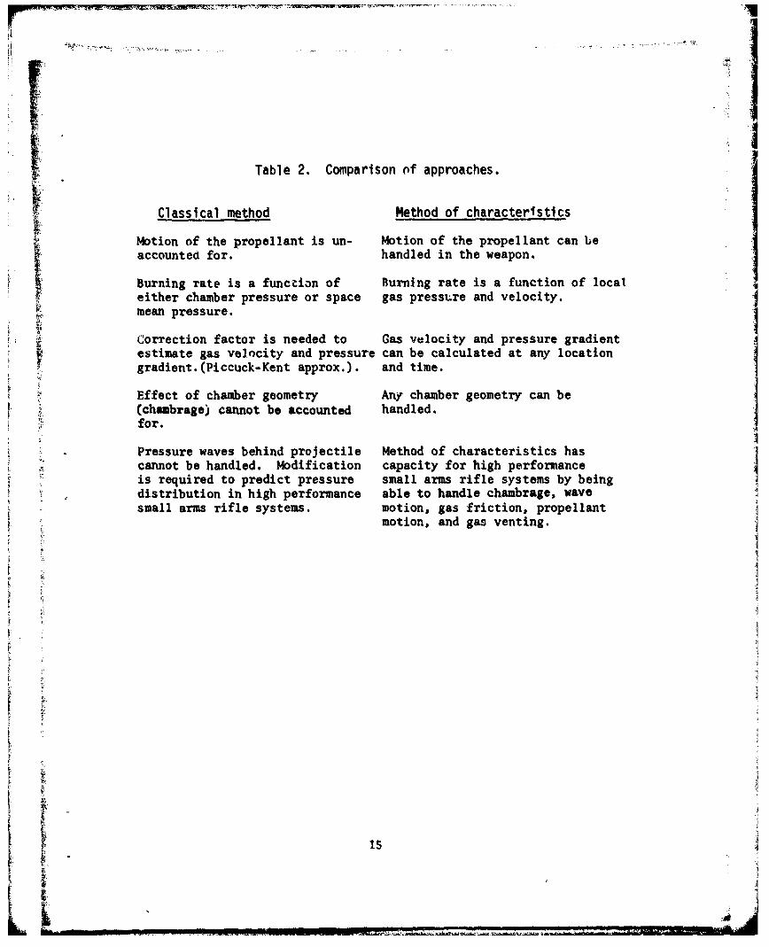
A two-phase flow model by which one can take into account shockwaves in the barrel has also been developed (ref. 47). With thismodel, one can use the method of characteristics to solve the mixedhyperbolic-parabolic equation used to describe the system. Thepotential advantages of models in which the method of characteristicsapproach is used over the classical models (such as the Baer-Franklemodel which use lumped parameters) are extracted from reference 48and listed in table 2.
Several interior ballistic models (ref. 49, 50) have evolved inwhich the Lagrangean form of the equations is used for time dependentfluid flow. Joglekar and Phadke use an interactive model buildingapproach to build their interior ballistics model (ref. 50).
14
rIM
Table 2. Comparison of approaches.
Classical method Method of characteristics
Motion of the propellant is un- Motion of the propellant can beaccounted for. handled in the weapon.
SBurning rate is a function of Burning rate is a function of localeither chamber pressure or space gas pressure and velocity.mean pressure.
Correction factor is needed to Gas velocity and pressure gradientestimate gas velocity and pressure can be calculated at any locationgradient. (Piccuck-Kent approx.). and time.
Effect of chamber geometry Any chamber geometry can be(chambrage) cannot be accounted handled.
= ffor.
Pressure waves behind projectile Method of characteristics hascannot be handled. Modification capacity for high performanceis required to predict pressure small arms rifle systems by beingdistribution in high performance able to handle chambrage, wavesmall arms rifle systems. motion, gas friction, propellant
motion, and gas venting.
ii
.I

tiSPECIAL ASPECTS Or SMALL ARMS INTERIOR BALLISTICS
Small arms interior ballistics systems have characteristics
that am.e quite different from larger caliber systems. Small armssystems are normally cycled by gas energy from the propellant gases.This function requires the gases to leave the barrel some time beforemuzzle exit and to continue escaping for a considerable length oftime afterward. As a result, enough gas can be removed from thebarrel to affect the ballistic performance of the system. Also,since many types of small arms are shoulder-fired, some gas energymay be used in the weapon recoil (ref. Si). The small bore area ofsmall arms also creates greater problems with heat transfer anderosion (ref. 52).
Gas Transmission Systems
Many small arms syst',ms are gas-operated automatic weapons thathave a gas-driven meuhanism to operate the bolt and its associatedmoving components. The timing and pressure of the ga•s cylinder areregulated by the location of the port along the barrel and by thediameter of the orifice through which the gas flows.
Several types of gas systems are used in swall arms systemstoday (refs. 53,54,55). In some systems, gases pour into a gaschamber when the p rojectile passes the port. This then results inpress-re on a piston whose motion is delayed by bolt locks that arerot released until chamber pressure has dropped to safe levels forcartridge caje extra..tion.
Another system that has been extensively studied (refs. 56-60)inc( rporates a long gas tube through which a portion of the pro-pellant gas in the barrel, drawn cff when the bullet pasges the port,is sent to a bolt mechanism in the r.ar of the rifle to cycle theweapon.
In e.esig,,ing pxessure ports in automatic weapons, Beans (rSf. 53)assumes that the flow is incompressible and turbulent and that thepressure losses •nrough th3 different passages are determined frompipe fitting data in which nozzle and diffuser efficiencies are used.He t,lso treats in detail the flow into a power cylirder where aconnecting rod is actuated.
Spurk (ref. 55) obtains a solution to the problem of describingthe flow in the gas tube by making use of the method of matchedasymptotic expansions. He also assumes a simple polytropic relation-ship bitween the pressure and temperature to specify these parametersat the port after the projectile has passed:
16

Similarily, he uses incompressible flow contraction coefficients todescribe the decrease in mass flow through the port.
Using the method of characteristics approach (table 2), Goldstein(ref. 58) simulated the compression and shock waves measured by
ITHorchler (ref. 61) in the gas tube. Experimental data of the flowof the gases through the port have been obtained and a theoreticalmodel (ref. 62) developed to describe both the nonsteady flow thatoccurs when the projectile first passes the port and the quasi-steadyflow following port opening. In this model, the method of charac-teristics is used to describe the nonsteady flow from the barrel andthrotigh the port, and a two-dimensional compressible potential flowsolution employing the Karmen-Tsien pressure correction formula isused to describe the quasi-steady flow.
After the projectile leaves the barrel, Hugoniot's equations(ref. 38) are used to describe the flow of the gases from the muzzle.Also, through the use of the Lagrange approximation, the fluid proper-ties in the barrel at ti:- port location are determined and, therefore,
I the boundary conditions for the flow through the port are specified.More recently, (ref 63) interest has been directed toward finding athree-dimensional viscous tube flow by which the Lagrange's approxi-mation can be satisfied.
SPressure Waves
Shock waves and/or combustion instabilities have often beenobserved in the testing of guns (refs. 64-67). Since the start ofthe work done by Kuo (ref. 68) mathematical models have been developedto the extent that these ballistics anomalies can now be partly under-stood.
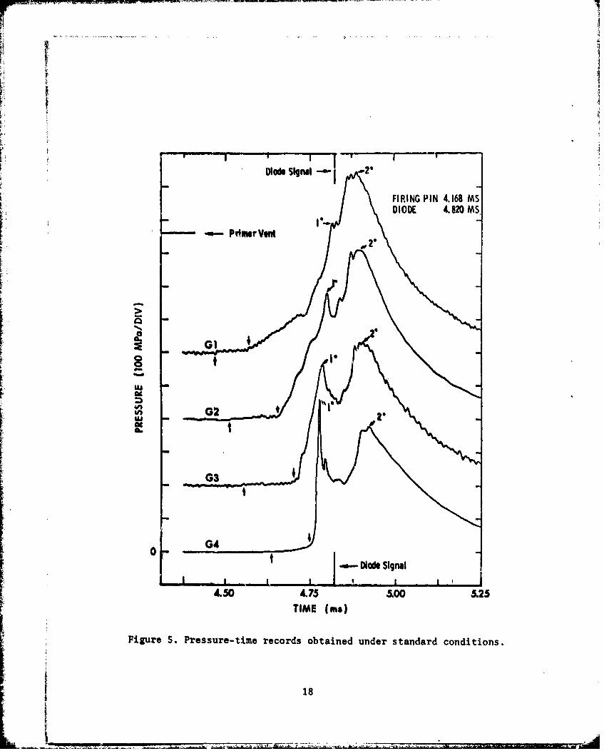
Kitchens (ref. 69) and Gerri (ref. 70) have used the method ofcharacteristics to extend the KVS model (ref. 68) over a differentlength propellant bed. Recent work (ref. 71) done by Gnrri with the-use of a 7.62 m I.D. vented bomb with a shear disc indicates (figs.
t S 5Sand 6) that:
V
17
L -. _
3o6
Diode Ssigul -...
FIRING PIN 4.168 MSDIODE 4.820 MS,
at
II
' 2 "
G2I
0 G4
Diode Signal
4.50 4.75 a00 5.25
TIME (ms)
Figure 5. Pressure-time records obtained under standard conditions.
18

741
IE >
-1 4)
4D4
49 a9

ri-i
1. The initial primer pulse and the primer vent geometryset the stage for all subsequent evernts.
2. Intergranular pressure transmission contributes to theruptur3 of the shear disc.
3. Propellant grain deformation and frictional forces atthe chamber walls greatly affect. the progress of the combustion wavethrough the propellant bed.
Experimental studies (ref. 72) have been conducted on 7.62 mmblank ammunition. These indicate (figs. 7-9) the multiple reflectiolis
L' of shock waves and characteristic waves within the barrel between themonth of the cartridge case and the blank firing attachment (BFA). Thecomputer code by which the problem of two-phase flow in a small armsbarrel is solved with shock waves has also been developed (ref. 73).Compression waves and shock waves have also been evidenced (ref. 75)in the gas transmission system of some small arms weapons. High-speedphotographic studies of small arms firings in a windowed chamber gunhave been conducted to gain insight on primer and flaefront phenomena(ref. 74).
A survey (ref. 76) of recent studies in large caliber weaponsindicates that the basic mechanisms responsible for generating pres-sure oscillations in gun systems are associated with the ignition andcombustion phases and early projectile motion phase of the interiorballistic cycle.
SCONCLUSIONS AND RECOMENDATIONS
Although there are many different types of small arms interior
ballistics models, each has certain advantages for specific applica-tions. However, considerably more experimental testing and modelingare required to determine such quantities as:
1. Engraving, friction, and air pressure forces.
2. Strain energy or work dore in deforming barrel walls.
3. Shot start pressures.
4. Recoil energy.
20

I/I
bo
r4•
21•
oI
0U
0)
I-
21 i
211

m U -. ~ r . . Pb-- - r -
4)
41
'p4
4.)rp4
tt
911M
4)
4R 4
22

4n4(A
C~
'I4
0) 0
0 U ;
232
[ 5. Kinetic energy of propellant grains.
6. Propellant gas frictional energy.
7. Gas leakage.
8. Pressure transients.
9. Erosion factors.
to The emiialmdl have been programmed and successfully usedto redct heperformance of different system designs. They areparicuarl usfulin performing system analysis for proposed new
weapon requirements. The analytical models have particular applica-tion to ammunition design. They can be used to determine the effectof variations in propellant compositions, deterrent concentrations,
grain dimensions, and geometry on interior ballistics performance.
chne ri rcsigtcnlg speevn h ytmThey are also a means of determining where a specification may beI
characteristics. Interim ballistics models provide the informationneeded to determine whether enough energy is available to properlycycle the weapon so that it can function reliably. They also supplyinput data for the neat transfer and erosion models used to predictI
barrel temperature and wear.
24

REFERENCES
1. AMCP 706-150, "Engineering Design Handbook, Ballistic Series,Interior Ballistics of Guns," U.S. Army Materiel Command, pag, s2-41, February 1965
2. H.P. Manning, "Interior Ballistics Small Army AmmunitionExperimental," Frankford Arsenal Report R-859, June 1948
3. C.M. Dickey, "Interior Ballistic Calculations Using the ManningCurves," Frankford Arsenal DF, SARFA-MDS-B, 17 December 1975
4. 4.S. Powley, "Ballistic Notes by Powley," Frankford ArsenalInterim Report 28-MDC-A-76, September 1976
S. C. Cranz, "Textbook of Ballistics," (Translation by C.C. Bramble,et al, Office of Technical Services, Washington, DC 1926I 6. M.E. Levy, "The Uses of Deterrents in Small Arms Propellants -
A Comprehensive Review," Frankford Arsenal Report FA-TR-76004,April 1976
7. M.E. Levy, "Microscopic Studies of Ball Propellant," FrankfordArsenal Report R-1286, September 1955
8. J.B. Quinlan, "A Microscopic Examination of Extruded Double BasePropellants," Frankford Arsenal Report R-1302, Decemter 1955
9. J.B. Quinlan, "Microscopic Studies of an Extruded Single Base IPropellant," Frankford Arsenal Memorandum Report MR-623, April1956
10. A.H. Milford, "Fundamental Studies of Propellants - FurtherStudies of the Diffusion of Nitroglycerin and Dibutylphaelatateinto Ball Powder," Olin Corporation, Winchester Western DivisionTechnical Report WWR-68-2, 15 January 1968
I 11. B.W. Brodman, M.P. Devine, and M.T. Gurbarg, "Hydrogen Bonding inNitrocellulose and its Implication on Deterring of Small ArmsPropellants," Journal Macromolecular Sci.-Chem. A8 (4), 837-841(1974)
12. "Autoradiographic Determination of Debutylphthalate in Nitro- Jcellulose Base Propellants," Olin Corporation, Final ProgressReport for Period 31 August - 30 November 1970, Contract DAAA-25-70-C-0140
2S

13. B.W. Brodman, M.P. Devine, R.W. Finch, M. Mac Claren, "Autoradio-graphic Determination of Di-n-butyl Phthalate ConcentrationProfile in a Nitrocellulose Matrix," Journal of Applied PolymerScience, 18, 12, 3739-3744, December 1974
14. L. Stiefel, R.M. Davis, "Burning Behavior of Several TypicalSmall Arms Propellants for Closed Bombs and in Guns," FrankfordArsenal Memorandum Report M70-31-1, September 1970
15. M.E. Serebryakov, Interior Ballistics; Moscow, U.S.S.R. StatePrinting House of the Defense Industry (2nd ed.), (Air TechnicalIntelligence Translation, Wright-Patterson AFB, HD 676, 241) 1949
16. P.W. Riefler, D.J. Lowery, "Linear Burn Rate of Ball PropellantsBased on Closed Bomb Firings," prepared by Olin Corp., EnergySystems Operations, East Alton, IL,BRL Contract Report 172,August 1974
17. T.R. Trafton, "An Improved Interior Ballistic Model for SmallArms Using Deterred Propellants," BRL Report 1624, November 1972
18. Private communication, 6 December 1977
19. D.L. Gottlieb, H. Kahn, J.A. Panone, and L. Stiefel, "Progres-sivity Studies on Deterred Propellants-Closed Bomb Simulationand Experimental Firings," Journal of Ballistics, Volume 1,Number 1, pages 13-19, 1976
20. P.G. Baer, J.M. Frankle, "The Simulation of Interior BallisticPerformance of Guns by Digital Computer Program," BRL Report1183, December 1962
21. S. Goldstein, "A Simplified Model for Predicting the BurningRate and Thermochemical Properties of Deterred/Rolled BallPropellant," Frankford Arsenal Technical Note TN-1184, December1973
22. S. Goldstein, "Burning Rate Model for Nondeterred Rolled BallPropellant," Frankford Arsenal Technical Note TN-1144, February
1970
Al
26
1-... ..................................

23. S.L. Soo, "Fluid Dynamics of Multiphase Systems," BarsdellPublishing Co., Waltham, MA, 1967
24. C.W. Kitchens, "Parametric Sensitivity Study of a NumericalModel for Flame Spreading," BRL Memorandum Report 2546, October1975
25. S.S. Zabrodsky, "Hydrodynamics of Heat Transfer in FluidizedBeds," The M.I.T. Press, Cambridge, MA, 1966
26. C.M. Smith, "An Interior Ballistics Model for Rolled BallPropellant, Part II, A Computer Implementation (TB MRB),"Frankford Arsenal, Memo Report M71-7-1, March 1971
27. Private communication, 6 December 197728. C. Huggett, C.E. Bartley, M.M. Mills, "Solid Propellant Rockets,"
Princeton University Press, Princeton, NJ, 1960
29. L. Shulman, J. Harris, C. Lenchitz, "Burning Characteristics ofStandard Gun Propellants at Low Temperatures (21 0 C to -52 0 C),Picatinny Arsenal Technical Report FRL-TR-41, November 1961
7• 30."Calculation of Gas Horsepower," Chemical Propulsion Division,Hercules Powder Co., Wilmington, DE
31. G.K. Adams, "The Chemistry of Solid Propellant Combustion NitTateEster or Double Base Systems," Mechanics and Chemistry of SolidPropellants, Proceedings of the Fourth Symposium of NavalStructural Mechanics, Pergamon Press, 1967
32. S. Goldstein, "Study of the Temperature Effects on the BallisticPerformance of 5.56 mm Ammunition," Frankford Arsenal ReportFA-TR-76008, February 1976
33. C.L. Fulton, E.E. Shindler, F.J. Shinaly, "Special Tests of5.56 mm Ammunition," Frankford Arsenal Report R-1883, February1968
34. M.M. Ibiricu, W.P. Aungst, F.A. Williams, "Effect of F.xternalSThermal' Radiation on the Burning Rate of Double-Base SolidPropellants Steady Stimulus," BRL Report 1757, February 1975
27

35. R.A. Fifer, "Shock Tube Study of High Temperature Kinetics,and Mechanisms of Nitrogen Dioxide-Aldehyde Reactions forPropellant Combustion Modeling," Frankford Arsenal SpringTechnical Symposium, February 1975
36. H.H. Kirshner, W.F. Ashley, M.E. Levy, "An Explanation ofFactors Responsible for Pressure-Temperature," FrankfordArsenal Memorandum for Record, August 1974 ("Dependency ofBall Powder at Low Temperature").
37. W.F. Ashley, "Brittle Fracture of Ball Propellant," FrankfordArsenal Report R1360, November 1956
38. J. Corner, "Theory of the Interior Ballistics of Guns,"John Wiley and Sons, Inc., New York, NY, 1950
39. B.B. Grollman, P.G.Baer, "Development of a Pidduck-Kent Functionfor Gun Interior Ballistic Computations," BRL Report 1519,DeL.Lber 1570
40. Private communication, 6 December 1977
41. S. Gcldstein, "Study of the Pressure Distribution Behind theM193 Projectile when Fired in the M16 Rifle Barrel," FrankgordArsenal Report R-2066, January 1973
42. F.R.W. Hunt, Chairman, Editorial Panel, Interior Ballistics,New York, Philosophical Library, 19S1
43. J. Corner, Theory of the Interior Ballistics of Guns, New York,John Wiley and Sons, Inc., 1950
44. M.J. Adam, H. Krier, "Calculation of Interior Heat Transfer inSmall Diameter Gun Barrels Using Solution of the CompressibleBoundary Layer Behind a Moving Projectile," Proceedings of theTri-Service Gun Tube Waar and Erosion Symposium, 29-31 March 1977
45. E.B. Fisher, "Determination of Temperature Gradients in 5.56 mmAluminum Cases," Final CAL Report CM-2962-Z-1, Contract DAAG25-70-C-0417, Cornell Aeronautical Laboratory, Inc., Buffalo, NY,Prepared for Frankford Arsenal, Philadelphia, PA, June 1972
46. K.K. Kuo, "A Summary of the JANNAF Workshop on TheoreticalModeling and Experimental Measurements of the Combustion andFluid Flow Processes in Gun Propellant Charges," 13th JANNAFCumbustion Meeting, Volume I, Chemical Propulsion InformationAgency, Johns Hopkins Univ, Applied Physics Lab, Johns HopkinsRoad, Laurel, MD, September 1976
28
"If

47. D.L. Tuckmantel, P.C. Chow, "TWO FLO-A Computer Code to Solvethe Problem of Two-Phase Flow with Shocks in a Duct," BRLReport 265, (Prepared by Dyna East Corporation, Wynnewood, PA19096) October 1975
48. S. Goldstein, E.V. McAssey, "Gas Flow and Heat Transfer inSmall Arms Weapons," 12th JANNAF Combustion Meeting, Vol 1,August 1975, Chemical Propulsion Information Agency, JohnsHopkins University, Applied Physics Laboratory, Laurel, MD
49. P.G. Baer, "A Mass Point Computer Program for the Gas DynamicProblem of High Velocity Gun Interior Ballistics," 2nd ICRPG/AIAA Solid Propellant Meeting, Anaheim, CA, June 1967
50. A.M. Joglekar, M.S. Phadke, S.M. Wu, "Interactive Modeling ofInterior Ballistics of Small Arms," Journal of Spacecraft and
C7 Rockets, Vol 10, No. 7, July 1977
51. P.E. Ehle, A.E. Rahe, "Theory and Application of MathematicalModeling of Shoulder Fired Weapons, Part 1: M16A1 Rifle,"Research Directorate, SARRI-LR-S, Gen Thomas J. Rodman Laboratory,Rock Island Arsenal, Rock Island, IL 61201
K 52. Proceedings of the Tri-Service Gun Tube Wear and ErosionSymposium, Sponsored by American Defense Preparedness Associa-
tion at U.S. Army Armament Research and Development Command,Dover, NJ , 29-31 March 1977, Editors Jean-Paul Picard; IqbalAhmad
53. AMCP760-260, Engineering Design Handbook, Gun Series, Automatic
Weapons, Army Material Command, February 1970
54. E.W. Beans, "Weapon Dynamics-Gas Dynamics Study," WECOM ReportSSWERR-TR-72-79, Contract DAAF05-70-C-C05, for WECOM, June 1971
55. S. Goldstein, R. Zeitz, L. DeStephano, C. Bateman, "AmmunitionWeapon Interface of the 6 mm Dual Piston Squad Automatic Weapon(SAW)," Frankford Arsenal Report FA-TR-75036, May 1975
S6. J.H. Spurk, "The Gas Flow in Gas-Operated Weapons," BRL Report1475, February 1970
57. W.M. Werner, "Comparison of a Theoretical and Experimental Studyof the Gas System in the M16A1 Rifle," BRL Report 1548, August1971
29
ii.

58. N. Gerber, "Sensitivity Study of Rifle Gas Systems," BRL Report1524, January 1971
59. S. Goldstein, "Model for the Gas Transmission System of theM16A1 Rifle," Frankford Arsenal Report R-3009, May 1974
60. W.B. Brooks, "Semiempirical Model for Predicting the UpperSize of Solid Particles Migrating from the Barrel to the GasTube of the M16AI Rifle," Frankford Arsenal Report R-2018, 1971
61. M. Horchler, "Experimental Study of the Flow Characteristics inthe Gas Tube of the M16A1 Rifle," Frankford Arsenal TechnicalNote TN-11SO, April 1970 j62. S. Goldstein, "Study of the Gas Flow' Through the Pressure
Port in a Gas-Operated Small Arms Automatic Weapon," FrankfordArsenal Report PA-TR-76059, November 1976
63. A.K.R. Celmins, "Critical Review of One-Dimensional Tube FlowEquations," BRL Report 2025, October 1977
64. AGARD Conf. Proc No. 10, "The Fluid Dynamics Aspects of Ballistics,"Clearinghouse, U.S. Dept Com, Nat Bur Stds, Springfield, VASeptember 1966
65. J.B. Goode, D.E. Weald, "Fluid Dynamic Aspects of InternalBallistics of Guns," AGARD Conf Proc No. 10, 1966
66. L.E. Brownell, "Pressure Excursions Explained," HandloaderMagazine #12, Pg 18, March-April 1968
67. S.Goldstein, P. Gordon, M. Horchler, "Small Arms CartridgeCase Extraction Study," Frankford Arsenal Report R-3n08,May 1974 (Appendix A)
68. K.K. Kuo, R. Vichenevetsky, M. Summerfield, "Generation of anAccelerated Flame Front in a Porous Propellant," AIAA Paper71-210. Presented at the AIAA of the Aerospace Sciences Meeting,New York, January 1971
69. C.W. Kitchens, "Flame Spreading in Small Arms Ball Propellant,"BRL Report 160L, August 1972
70. C.W. Kitchens, N.J. Gerri, "Numerical and Experimental Investi-gation of Flame Spreading and Gas Flow in Gun Propellants,"Proceedings of the 9th JANNAF Combustion Conference, Monterey,
CA, Vol 1, Sep 71, CPTA Pub No. 231, Dec 72, pg 115-125
30

71. N.J. Gerri, "A Parametric Study of Gas Fow and Flame Spreadingin Packed Beds of Ball Propellant. Part 1: The 108.4 mmn Chamberwith 7.62 mm I.D.," BRL Report 1988, May 1977
72. S. Goldstein, "Qualitative Investigation of the Functioning of7.62 mm Blank Ammunition," Frankford Arsenal Technical NoteTN-1141, June 1969
73. D.L. Tuckmantel, P.C. Chow, "Two Flo-A Computer Code to Solvethe Problem of Two-Phase Flow with Shocks in a Duct," BRLContract Report 265, Prepared by DynaRast Corporation, October1975
74. H.A. Kirshner, L. Stiefel, "Propellant Ignition in Small Arms,Part IV: High Speed Motion Pictures of Firings in Windowed Gun."Frankford Arsenal Report R-1353, October 1956
75. M. Horchler, "Experimental Study of the Flow Characteristics inthe Gas Tube of the M16Al Rifle," Frankford Arsenal ReportTN-11S0, April 1970
76. A.J. Budka, J.D. Knapton, "Pressure Wave Generation in GunSystems A Survey," BRL Report 2567, December 1975
ifi31
VA

- -i
DISTRIBUTION LIST
CommanderU.S. Army Armament Research 6 Development CommandATTN: DRDAR-TD
DRDAR-SCDRDAR-SCA-T (20)DRDAR-SCA-SDRDAR- SCA-WDRDAR-SCMDRDAR-SCSDRDAR-SCS-MDRDAR-TSS (S)
Dover, NJ 07801
CommanderDefense Documentation Center (12)Camerson StationAlexandria, VA 22314
Weapon System Concept Team/CSLATTN: DRDAR-ACWAberdeen Proving Ground, MD 21010
Technical LibraryATTN: DRDAR-CLJ-LAberdeen Proving Ground, MD 21010
Technical LibraryAT•N: DRDAR-TSB-SAberdeen Proving Ground, MD 2100S
Benet Weapons LaboratoryTechnical LibraryATTN: DRDAR-LCB-TLWatervliet, NY 12189
DirectorBallistic Research LaboratoryU.S. Army ARRADCOM[ ATTN: Mr. B. Grollman (DRDAR-BLP)
Mr. T. Trafton,(DRDAR-BLP)Aberdeen Proving Ground, MD 2100S
33

Ii
CommanderU.S. Army Armament Materiel Readiness CommandATTlc!: DRSAR-LEP-LRock Island, IL 61299
DirectorU.S. Army TRADOC Systems Analysis ActivityATTN: ATAA-SL (Technical Library)White Sands Missile Range, NM 88002
CommanderU.S. Army Materiel Systems Analysis ActivityATTN: DRXSY-MPAberdeen Proving Ground, MD 21005
I
I •
34


