782Slides-3
14
Mohammad M. Banat – EE 782: Advanced Wireless Communications II: Orthogonal Frequency Division (OFDM) Systems II.1-Multicarrier Modulation and OFDM 26 II. ORTHOGONAL FREQUENCY DIVISION (OFDM) SYSTEMS II.1. Multicarrier Modulation and OFDM The basic idea of multicarrier modulation is to divide the transmitted bit stream into many different sub-streams and send these over many different sub-channels. Typically the sub- channels are orthogonal under ideal propagation conditions. The data rate on each of the sub- channels is much less than the total data rate, and the corresponding sub-channel bandwidth is much less than the total system bandwidth. The number of sub-streams is chosen to insure that each sub-channel has a bandwidth less than the coherence bandwidth of the channel, so the sub- channels experience relatively flat fading. Thus, the ISI on each sub-channel is small. The sub- channels in multicarrier modulation need not be contiguous, so a large continuous block of spectrum is not needed for high rate multicarrier communications. Moreover, multicarrier modulation is efficiently implemented digitally. Orthogonal frequency division multiplexing (OFDM) is based on the principle of multicarrier modulation. OFDM can be regarded both as a modulation method and a multiple-access technique. OFDM has been shown to be an effective technique to combat multipath fading in wireless communications. OFDM has been chosen as the standard for digital audio broadcasting and digital terrestrial TV broadcasting in Europe and high-speed wireless local areas networks. OFDM is used in high-bit-rate wireless applications. OFDM suffers limitations caused by the wireless environment. OFDM can overcome these inherent bit rate limitations. Figure II.1 II.2. Channel Impairments II.2.A. PATH LOSS Different, often complicated, models are used for different environments. A simple model for path loss, L , is: 1 r t P L K P d (II.1)
-
Upload
just-ismail -
Category
Documents
-
view
219 -
download
0
Transcript of 782Slides-3
Mohammad M. Banat – EE 782: Advanced Wireless Communications II: Orthogonal Frequency Division (OFDM) Systems
II.1-Multicarrier Modulation and OFDM 26
II. ORTHOGONAL FREQUENCY DIVISION (OFDM) SYSTEMS
II.1. Multicarrier Modulation and OFDM
The basic idea of multicarrier modulation is to divide the transmitted bit stream into many different sub-streams and send these over many different sub-channels. Typically the sub-channels are orthogonal under ideal propagation conditions. The data rate on each of the sub-channels is much less than the total data rate, and the corresponding sub-channel bandwidth is much less than the total system bandwidth. The number of sub-streams is chosen to insure that each sub-channel has a bandwidth less than the coherence bandwidth of the channel, so the sub-channels experience relatively flat fading. Thus, the ISI on each sub-channel is small. The sub-channels in multicarrier modulation need not be contiguous, so a large continuous block of spectrum is not needed for high rate multicarrier communications. Moreover, multicarrier modulation is efficiently implemented digitally. Orthogonal frequency division multiplexing (OFDM) is based on the principle of multicarrier modulation. OFDM can be regarded both as a modulation method and a multiple-access technique. OFDM has been shown to be an effective technique to combat multipath fading in wireless communications. OFDM has been chosen as the standard for digital audio broadcasting and digital terrestrial TV broadcasting in Europe and high-speed wireless local areas networks. OFDM is used in high-bit-rate wireless applications. OFDM suffers limitations caused by the wireless environment. OFDM can overcome these inherent bit rate limitations.
Figure II.1
II.2. Channel Impairments
II.2.A. PATH LOSS
Different, often complicated, models are used for different environments. A simple model for path loss, L , is:
1r
t
PL K
P d (II.1)

Mohammad M. Banat – EE 782: Advanced Wireless Communications II: Orthogonal Frequency Division (OFDM) Systems
II.2-Channel Impairments 27
where rP is the local mean received signal power, tP is the transmitted power, and d is the
transmitter-receiver distance. The path loss exponent 2 in free space; 2 4 in other environments.
II.2.B. SHADOW FADING
The received signal is shadowed by obstructions such as hills and buildings. This results in variations in the local mean received signal power,
, ,r dB r dB sP P G (II.2)
where 2(0, )s sG N and 4 10 dBs . Shadowing results in non-uniform coverage and
increases the required transmit power.
II.2.C. MULTIPATH
1
( ) ( )iL
ji i
i
h t a e t
(II.3)
The received multipath signals may interfere constructively or destructively.
II.2.D. FLAT FADING
The delay spread is small compared to the symbol period. The received signal envelope, r , follows a Rayleigh or Rician distribution.
Figure II.2
II.2.E. DOPPLER SPREAD
A measure of the spectral broadening caused by the channel time variation.
Dv
f
(II.4)
Example: 900 MHz, 60 mph, 80 HzDf . 5 GHz, 5 mph, 37 HzDf .

Mohammad M. Banat – EE 782: Advanced Wireless Communications II: Orthogonal Frequency Division (OFDM) Systems
II.2-Channel Impairments 28
II.2.F. DELAY SPREAD - TIME DOMAIN INTERPRETATION
When multipath is present, delay spread is defined as the difference in propagation time between the longest and shortest paths, counting only the paths with significant energy. The delay spread of the channel dictates its frequency coherence. Frequency coherence shows how quickly the channel changes in frequency. The frequency response at time t is given by:
2 ( )( , ) ( ) ij f ti
i
H f t a t e (II.5)
Figure II.3
Figure II.4
T small: negligible intersymbol interference (ISI).
T large: significant ISI.

Mohammad M. Banat – EE 782: Advanced Wireless Communications II: Orthogonal Frequency Division (OFDM) Systems
II.2-Channel Impairments 29
The contribution due to a particular path has a phase linear in f . For multiple paths, there is a
differential phase ( ) ( )2 i kt tf between the thi and thk paths. This differential phase
causes selective fading in frequency.
II.2.G. DELAY SPREAD - FREQUENCY DOMAIN INTERPRETATION
Figure II.5
T small: flat fading.
T large: frequency-selective fading. ISI causes an irreducible error floor. The RMS delay spread imposes a limit on the maximum bit rate. For example, for QPSK:
Channel RMS Delay Spread Maximum Bit Rate Mobile (rural) 25 μsec 8 kbps Mobile (city) 2.5 μsec 80 kbps
Microcells 500 nsec 400 kbps Large Building 100 nsec 2 Mbps
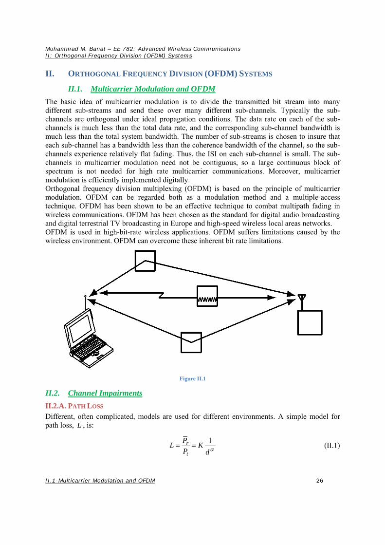
II.2.H. INTERFERENCE
Frequencies are reused often to maximize spectral efficiency. For interference-limited systems, the noise floor is dominated by co-channel interference.
1
6
S S D
I N I R
(II.6)
Mohammad M. Banat – EE 782: Advanced Wireless Communications II: Orthogonal Frequency Division (OFDM) Systems
II.3-Multicarrier Modulation 30
Figure II.6
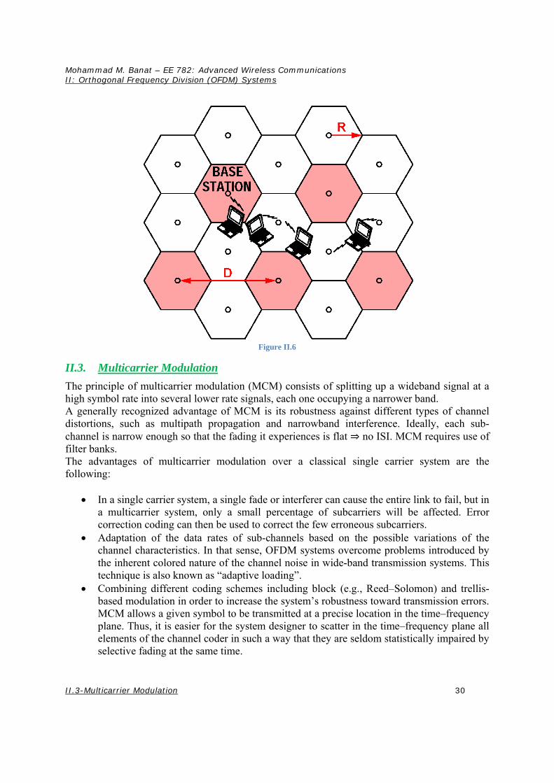
II.3. Multicarrier Modulation
The principle of multicarrier modulation (MCM) consists of splitting up a wideband signal at a high symbol rate into several lower rate signals, each one occupying a narrower band. A generally recognized advantage of MCM is its robustness against different types of channel distortions, such as multipath propagation and narrowband interference. Ideally, each sub-channel is narrow enough so that the fading it experiences is flat ⇒ no ISI. MCM requires use of filter banks. The advantages of multicarrier modulation over a classical single carrier system are the following:
In a single carrier system, a single fade or interferer can cause the entire link to fail, but in a multicarrier system, only a small percentage of subcarriers will be affected. Error correction coding can then be used to correct the few erroneous subcarriers.
Adaptation of the data rates of sub-channels based on the possible variations of the channel characteristics. In that sense, OFDM systems overcome problems introduced by the inherent colored nature of the channel noise in wide-band transmission systems. This technique is also known as “adaptive loading”.
Combining different coding schemes including block (e.g., Reed–Solomon) and trellis-based modulation in order to increase the system’s robustness toward transmission errors. MCM allows a given symbol to be transmitted at a precise location in the time–frequency plane. Thus, it is easier for the system designer to scatter in the time–frequency plane all elements of the channel coder in such a way that they are seldom statistically impaired by selective fading at the same time.

Mohammad M. Banat – EE 782: Advanced Wireless Communications II: Orthogonal Frequency Division (OFDM) Systems
II.3-Multicarrier Modulation 31
Figure II.7
Transmitter
Figure II.8
Receiver
Figure II.9
The frequency spectrum of the MCM signal is written as:
1
0
( , ) ( , )M
MCM mm
S f t F f t
(II.7)
where ( , )mF f t is the frequency spectrum of pulse waveform of the -thm subcarrier. Through a
frequency selective fading channel characterized by the transfer function ( , )H f t , the frequency spectra of received MCM signal can be written as:
( , ) ( , ) ( , )MCM MCMR f t H f t S f t (II.8)
When the number of subcarriers is large, the amplitude and phase response of ( , )H f t can be
assumed to be constant over the -thm sub-channel, so ( , )MCMR f t can be approximated as:
Mohammad M. Banat – EE 782: Advanced Wireless Communications II: Orthogonal Frequency Division (OFDM) Systems
II.3-Multicarrier Modulation 32
1
0
( , ) ( ) ( , )M
MCM m mm
R f t H t F f t
(II.9)
Equation (II.9) clearly shows that MCM is effective and robust in wireless channels; namely, to combat frequency selective fading, MCM requires no equalization or at most one-tap equalization for each subcarrier. Defining the symbol duration at subcarrier level as sT , the transmitted signal ( )s t is written as:
1
2 ( )
0
( ) ( )m sM
j f t iTmi s
i m
s t c e f t iT
(II.10)
where mic is the -thi information symbol at the -thm subcarrier, and ( )f t is the pulse
waveform of the symbol. When ( )f t is a rectangular waveform we have
1, 0
( )0, Otherwise
st Tf t
(II.11)
Therefore the subcarrier frequencies and the frequency separation are given by:
ms
mf
T (II.12)
1
s
fT
(II.13)
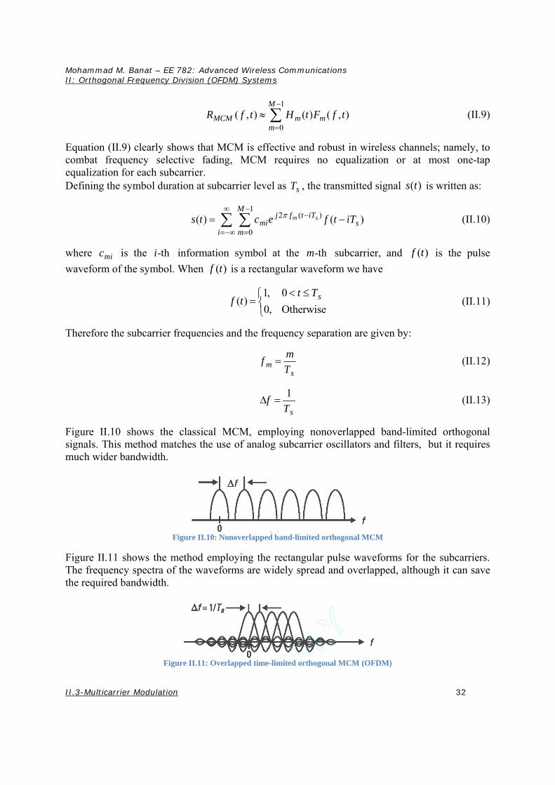
Figure II.10 shows the classical MCM, employing nonoverlapped band-limited orthogonal signals. This method matches the use of analog subcarrier oscillators and filters, but it requires much wider bandwidth.
Figure II.10: Nonoverlapped band-limited orthogonal MCM
Figure II.11 shows the method employing the rectangular pulse waveforms for the subcarriers. The frequency spectra of the waveforms are widely spread and overlapped, although it can save the required bandwidth.
Figure II.11: Overlapped time-limited orthogonal MCM (OFDM)
Mohammad M. Banat – EE 782: Advanced Wireless Communications II: Orthogonal Frequency Division (OFDM) Systems
II.3-Multicarrier Modulation 33
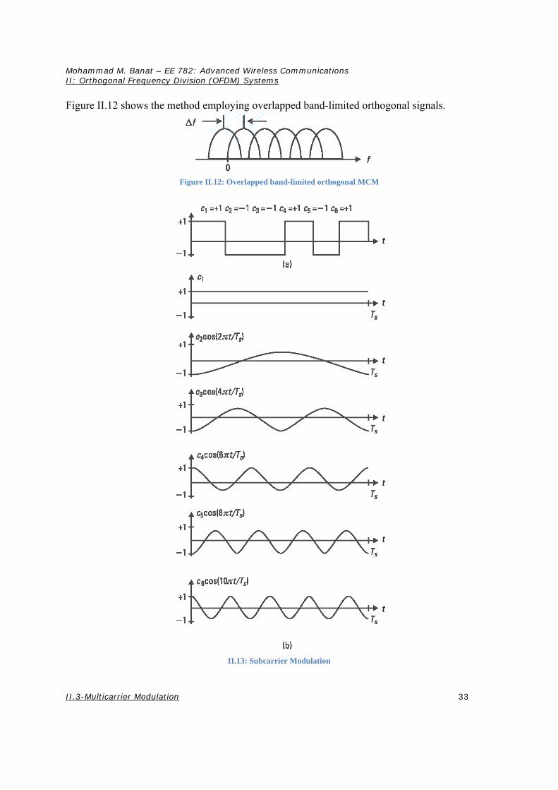
Figure II.12 shows the method employing overlapped band-limited orthogonal signals.
Figure II.12: Overlapped band-limited orthogonal MCM
II.13: Subcarrier Modulation
Mohammad M. Banat – EE 782: Advanced Wireless Communications II: Orthogonal Frequency Division (OFDM) Systems
II.4-Orthogonal Frequency Division Multiplexing
34
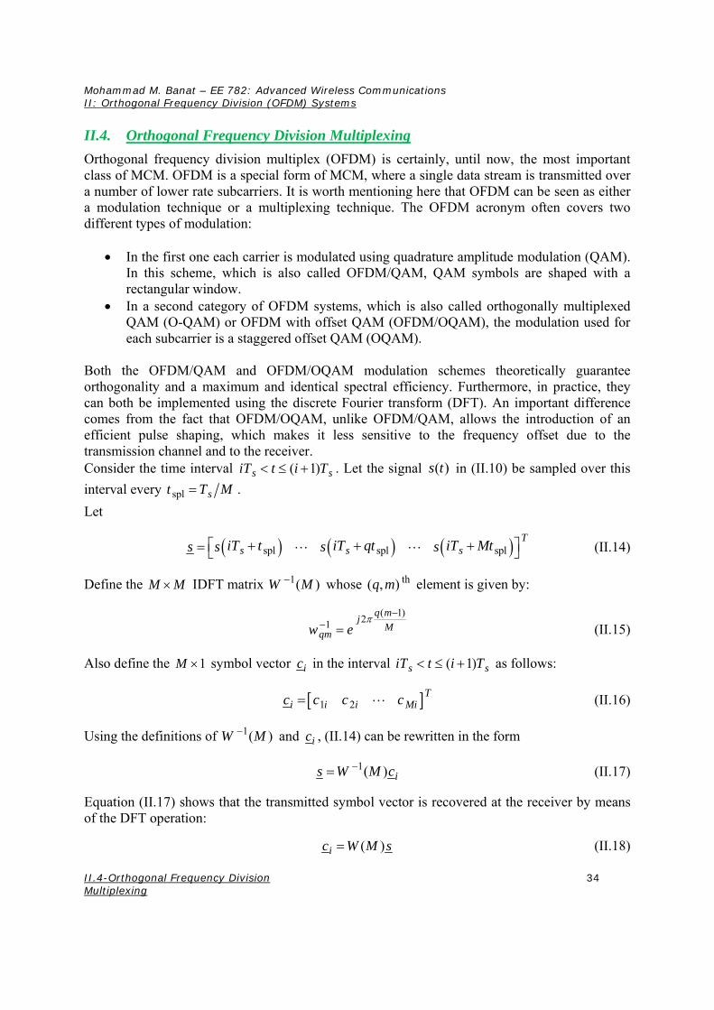
II.4. Orthogonal Frequency Division Multiplexing
Orthogonal frequency division multiplex (OFDM) is certainly, until now, the most important class of MCM. OFDM is a special form of MCM, where a single data stream is transmitted over a number of lower rate subcarriers. It is worth mentioning here that OFDM can be seen as either a modulation technique or a multiplexing technique. The OFDM acronym often covers two different types of modulation:
In the first one each carrier is modulated using quadrature amplitude modulation (QAM). In this scheme, which is also called OFDM/QAM, QAM symbols are shaped with a rectangular window.
In a second category of OFDM systems, which is also called orthogonally multiplexed QAM (O-QAM) or OFDM with offset QAM (OFDM/OQAM), the modulation used for each subcarrier is a staggered offset QAM (OQAM).
Both the OFDM/QAM and OFDM/OQAM modulation schemes theoretically guarantee orthogonality and a maximum and identical spectral efficiency. Furthermore, in practice, they can both be implemented using the discrete Fourier transform (DFT). An important difference comes from the fact that OFDM/OQAM, unlike OFDM/QAM, allows the introduction of an efficient pulse shaping, which makes it less sensitive to the frequency offset due to the transmission channel and to the receiver. Consider the time interval ( 1)s siT t i T . Let the signal ( )s t in (II.10) be sampled over this
interval every spl st T M .
Let
spl spl splT
s s siT t iT qt iT Mts s s s (II.14)
Define the M M IDFT matrix 1( )W M whose th( , )q m element is given by:
( 1)
21q m
jM
qmw e
(II.15)
Also define the 1M symbol vector ic in the interval ( 1)s siT t i T as follows:
1 2T
i i Mii c c cc (II.16)
Using the definitions of 1( )W M and ic , (II.14) can be rewritten in the form
1( ) is W M c (II.17)
Equation (II.17) shows that the transmitted symbol vector is recovered at the receiver by means of the DFT operation:
( )ic W M s (II.18)

Mohammad M. Banat – EE 782: Advanced Wireless Communications II: Orthogonal Frequency Division (OFDM) Systems
II.4-Orthogonal Frequency Division Multiplexing
35
where ( )W M is the M M DFT matrix whose th( , )q m element is given by:
( 1)
2q m
jM
qmw e
(II.19)
When employing rectangular DFT window at the receiver, intersubcarrier interference can be perfectly eliminated. The use of IDFT/DFT totally eliminates bank of subcarrier oscillators at the transmitter/receiver, and furthermore, if selecting the number of subcarriers as the power of two, we can replace the DFT by the fast Fourier transform (FFT). Block diagrams of the OFDM transmitter and receiver are shown in Figure II.14.
II.4.A. INSERTION OF CYCLIC PREFIX
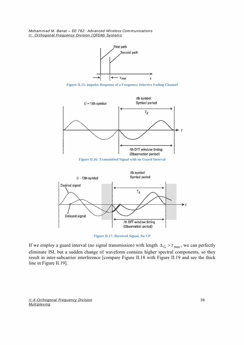
Frequency selective fading can be characterized by a channel impulse response with a delay spread in the time domain, which is not negligibly small compared to the symbol period. Consider the impulse response of a frequency selective fading channel shown in Figure II.15. Through the channel, the first path generates the desired signal and the second path generates the delayed signal at the receiver. Let the transmitted signal on one of the subcarriers be as shown in Figure II.16. Note that only the waveforms for a certain subcarrier ( 2m ) are shown. Without a guard interval between successive OFDM symbols, intersymbol interference (ISI) from the
th( 1)i symbol gives a distortion to the thi symbol (compare Figure II.16 with Figure II.17 and see the thick line in Figure II.17).
Figure II.14: OFDM TX and RX
Mohammad M. Banat – EE 782: Advanced Wireless Communications II: Orthogonal Frequency Division (OFDM) Systems
II.4-Orthogonal Frequency Division Multiplexing
36
Figure II.15: impulse Response of a Frequency Selective Fading Channel
Figure II.16: Transmitted Signal with no Guard Interval
Figure II.17: Received Signal, No CP
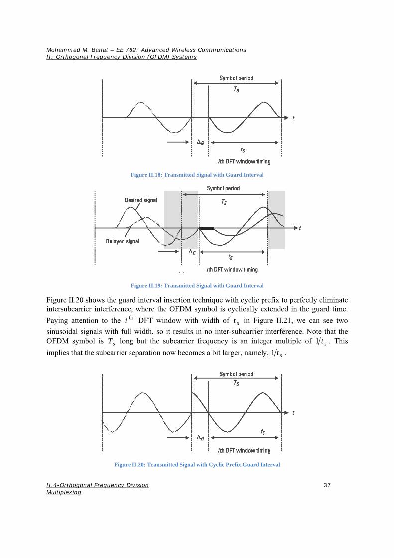
If we employ a guard interval (no signal transmission) with length maxG , we can perfectly
eliminate ISI, but a sudden change of waveform contains higher spectral components, so they result in inter-subcarrier interference [compare Figure II.18 with Figure II.19 and see the thick line in Figure II.19].
Mohammad M. Banat – EE 782: Advanced Wireless Communications II: Orthogonal Frequency Division (OFDM) Systems
II.4-Orthogonal Frequency Division Multiplexing
37
Figure II.18: Transmitted Signal with Guard Interval
Figure II.19: Transmitted Signal with Guard Interval
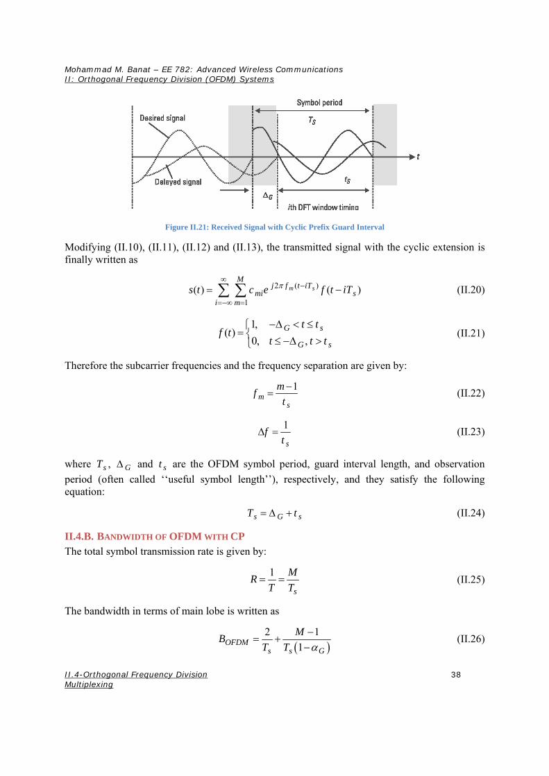
Figure II.20 shows the guard interval insertion technique with cyclic prefix to perfectly eliminate intersubcarrier interference, where the OFDM symbol is cyclically extended in the guard time.
Paying attention to the thi DFT window with width of st in Figure II.21, we can see two
sinusoidal signals with full width, so it results in no inter-subcarrier interference. Note that the OFDM symbol is sT long but the subcarrier frequency is an integer multiple of 1 st . This
implies that the subcarrier separation now becomes a bit larger, namely, 1 st .
Figure II.20: Transmitted Signal with Cyclic Prefix Guard Interval
Mohammad M. Banat – EE 782: Advanced Wireless Communications II: Orthogonal Frequency Division (OFDM) Systems
II.4-Orthogonal Frequency Division Multiplexing
38
Figure II.21: Received Signal with Cyclic Prefix Guard Interval
Modifying (II.10), (II.11), (II.12) and (II.13), the transmitted signal with the cyclic extension is finally written as
2 ( )
1
( ) ( )m sM
j f t iTmi s
i m
s t c e f t iT
(II.20)
1,
( )0, ,
G s
G s
t tf t
t t t
(II.21)
Therefore the subcarrier frequencies and the frequency separation are given by:
1
ms
mf
t
(II.22)
1
s
ft
(II.23)
where sT , G and st are the OFDM symbol period, guard interval length, and observation
period (often called ‘‘useful symbol length’’), respectively, and they satisfy the following equation:
s G sT t (II.24)
II.4.B. BANDWIDTH OF OFDM WITH CP
The total symbol transmission rate is given by:
1
s
MR
T T (II.25)
The bandwidth in terms of main lobe is written as
2 1
1OFDMs s G
MB
T T
(II.26)
Mohammad M. Banat – EE 782: Advanced Wireless Communications II: Orthogonal Frequency Division (OFDM) Systems
II.4-Orthogonal Frequency Division Multiplexing
39
where G is the guard interval factor, defined as
GG
sT
(II.27)
Therefore,
2 1
OFDMs s
MB
T t
(II.28)
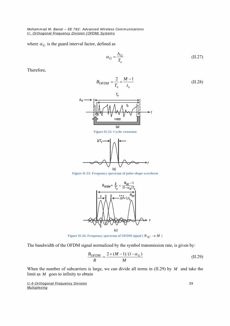
Figure II-22: Cyclic extension
Figure II-23: Frequency spectrum of pulse shape waveform
Figure II-24: Frequency spectrum of OFDM signal ( SCN M )
The bandwidth of the OFDM signal normalized by the symbol transmission rate, is given by:
2 ( 1) (1 )OFDM GB M
R M
(II.29)
When the number of subcarriers is large, we can divide all terms in (II.29) by M and take the limit as M goes to infinity to obtain