7748665 Interface Spec NY 20080318 Komplett Ver2
28
Electrical Interface Specification Industrial Engines Installation EM S & EM S2
-
Upload
thong-chan -
Category
Documents
-
view
221 -
download
0
Transcript of 7748665 Interface Spec NY 20080318 Komplett Ver2

8/17/2019 7748665 Interface Spec NY 20080318 Komplett Ver2
http://slidepdf.com/reader/full/7748665-interface-spec-ny-20080318-komplett-ver2 1/28
Electrical Interface SpecificationIndustrial Engines
Installation
EMS & EMS2

8/17/2019 7748665 Interface Spec NY 20080318 Komplett Ver2
http://slidepdf.com/reader/full/7748665-interface-spec-ny-20080318-komplett-ver2 2/28

8/17/2019 7748665 Interface Spec NY 20080318 Komplett Ver2
http://slidepdf.com/reader/full/7748665-interface-spec-ny-20080318-komplett-ver2 3/28
Contents
General .................................................................... 4
Related Documents ............................................... 4
Abbreviations ......................................................... 4
Engine control interface ........................................... 5
CIU ........................................................................ 5
DCU ....................................................................... 5
Stand alone (124x only) ........................................ 5
Electrical interface ................................................. 5
Power up sequence ............................................... 8
Start ....................................................................... 8
Power down sequence .......................................... 8
Stop ....................................................................... 8
Throttle (Synchronizing/Load sharing) .................. 9
Torque speed control ............................................. 9
Governor mode ................................................... 10
Idle switch ............................................................ 10
Preheat ............................................................... 11
Engine protection override .................................. 11
Frequency select ................................................. 12
Communication ...................................................... 13J1939 ................................................................... 13
J1587 ................................................................... 17
Diagnostics .......................................................... 19
Appendix A: Diagnostic table ................................. 20
Appendix B: VODIA parameters ............................ 24
8/17/2019 7748665 Interface Spec NY 20080318 Komplett Ver2
http://slidepdf.com/reader/full/7748665-interface-spec-ny-20080318-komplett-ver2 4/28
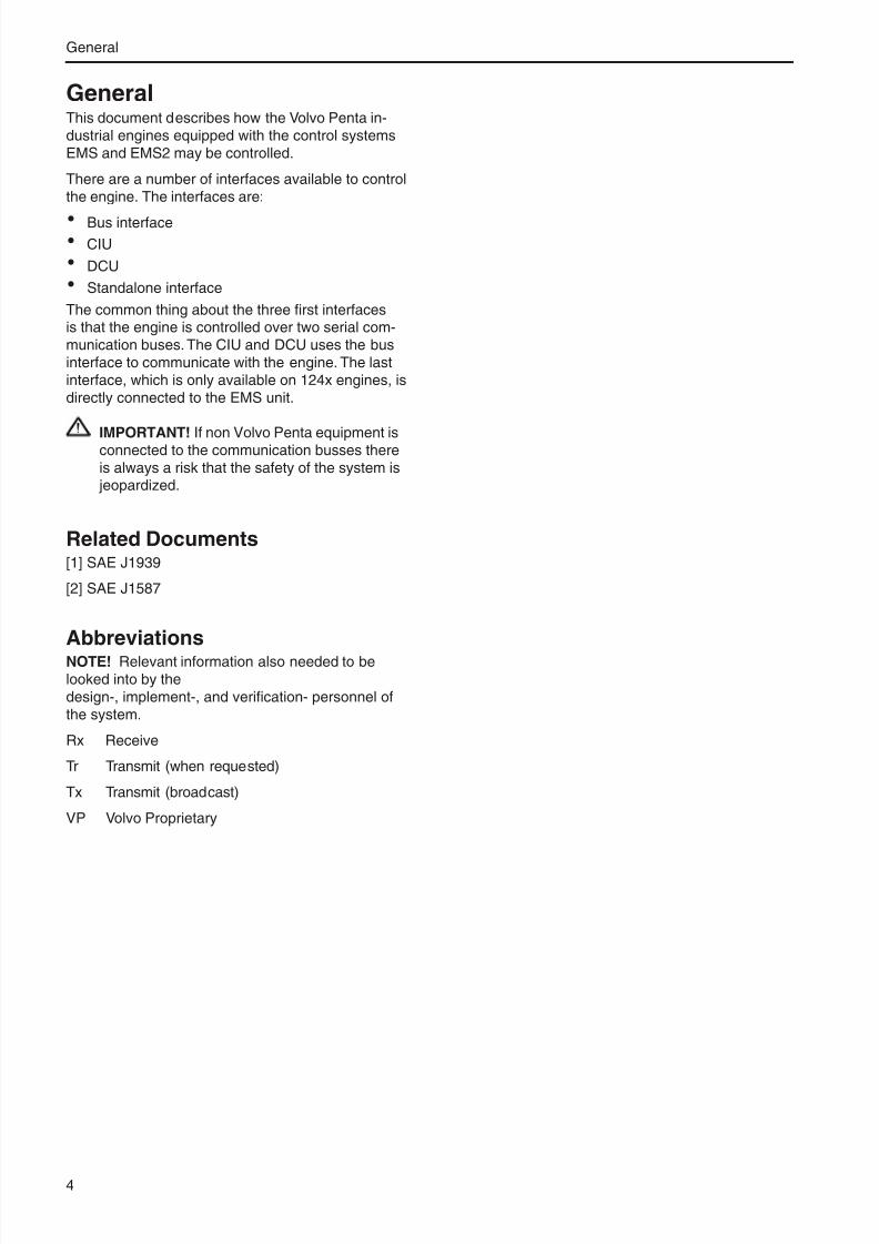
GeneralThis document describes how the Volvo Penta in-dustrial engines equipped with the control systemsEMS and EMS2 may be controlled.
There are a number of interfaces available to controlthe engine. The interfaces are:
· Bus interface
· CIU
· DCU
· Standalone interface
The common thing about the three first interfacesis that the engine is controlled over two serial com-munication buses. The CIU and DCU uses the businterface to communicate with the engine. The lastinterface, which is only available on 124x engines, isdirectly connected to the EMS unit.
IMPORTANT! If non Volvo Penta equipment isconnected to the communication busses thereis always a risk that the safety of the system is jeopardized.
Related Documents[1] SAE J1939
[2] SAE J1587
AbbreviationsNOTE! Relevant information also needed to belooked into by thedesign-, implement-, and verification- personnel ofthe system.
Rx Receive
Tr Transmit (when requested)
Tx Transmit (broadcast)
VP Volvo Proprietary
General
4

8/17/2019 7748665 Interface Spec NY 20080318 Komplett Ver2
http://slidepdf.com/reader/full/7748665-interface-spec-ny-20080318-komplett-ver2 5/28
Engine control interfacePentas industrial engines can be controlled in threedifferent ways. Via bus interface, CIU or DCU. Thebus interface is used by those who makes there owncontrol system that and wants to control the engineover SAE J1939 and J1587. Penta provided two dif-ferent systems to control the engines, CIU that pro-
vides a number of digital/analogue outputs to controlthe engine. And DCU that has all buttons included inthe unit but still provides some digital/analogue inputsand outputs.
CIUThis is the interface for those who wants to makethere control panel or non bus based control unit.
DCUThis is the interface for those who wants a completeunit that is ready to run the engine without make anybutton. But the possibility to make some customiza-tion is still here.
The DCU is equipped with a display that shows engi-ne data and diagnostics translated to text.
Stand alone (124x only)This is the interface for those who wants a complete
unit that is ready to run the engine without make anybutton. But the possibility to make some customa-tions is still here.
The DCU is equipped with a display that shows engi-ne data and diagnostics translated to text.
Electrical interface
Bus interface8 – pole deutsch connector recepticle.
Pin Description Pin Description
1 CAN H 2 CAN L
3 Battery – 4 Battery +
5 Ignition (Battery + switched) 6 Stop request
7 J1587A 8 J1587B
Engine Control Interface
5

8/17/2019 7748665 Interface Spec NY 20080318 Komplett Ver2
http://slidepdf.com/reader/full/7748665-interface-spec-ny-20080318-komplett-ver2 6/28
CIUThe electrical interface to the CIU is 42 – pole AMP connector.
Pin Description Pin Description
1 Idle request 2 Potentiometer ground
3 Potentiometer signal 4 Not used in this configuration
5 Not used in this configuration 6 Not used in this configuration
7 Over speed indication1, Buzzer2 8 Easy link bus
9 Coolant temperature alarm 10 Battery alarm
11 CAN L 12 CAN H
13 Gauge power supply 14 Battery –
15 Frequency select1 16 Diagnostic switch
17 Preheat request3 18 Not used in this configuration
19 Engine protection override req. 20 Oil temp gauge
21 Oil pressure gauge 22 J1587 A
23 Not used in this configuration 24 Preheat indication3
25 Coolant level alarm 26 Oil pressure alarm
27 Battery + 28 Ignition (key switch)
29 Governor mode request 30 Potentiometer supply
31 Not used in this configuration 32 Not used in this configuration
33 Tachometer 34 Coolant temperature gauge
35 Start request 36 Diagnostic indication
37 J1587 B 38 Running indication1
39 Fuel alarm 40 Oil temperature alarm
41 Stop request 42 Not used in this configuration
There is a cable harness available with all wires connected that applies to the above table.
All indicators shall be less than 3W. All switches are active when shorted to battery+.
________________
1 Genset only 2 Power pack only 3 Not for 124xGE
Engine Control Interface
6

8/17/2019 7748665 Interface Spec NY 20080318 Komplett Ver2
http://slidepdf.com/reader/full/7748665-interface-spec-ny-20080318-komplett-ver2 7/28
Stand alone23 – pole Deutsch connector.
Pin Description Pin Description
A Switch ground B Potentiometer ground
C Potentiometer signal D Frequency select4, governor mode5
E Start request F Idle request
G Preheat request5 H Stop request
I J Diagnosis request
K Diagnosis indication L Oil pressure alarm
M Coolant temperature alarm N Running ind4, Coolant level alarm5
O Over speed ind4, preheat ind5 P Ignition
Q Battery - R Battery +
S Potentiometer supply T
U V
W
All indicators shall be less than 3W. All switches are active when shorted to battery + except Frequency select/ governor mode witch shall be shorted to switch ground.
DCUConnector 1, 8-pole deutsch connector:
Pin Description Pin Description
1 CAN H 2 CAN L
3 Battery – 4 Battery +
5 Ignition (Battery + switched) 6 Stop request
7 J1587A 8 J1587B
Connector 2, 12-pole deutsch connector:
Pin Description Pin Description
1 External Stop 2 External Start / Ignition
3 LSS1 (Buzzer) 4 Easylink gauge power
5 Easylink Data 6 Easylink Ground
7 Throttle + (10V) 8 Throttle input
9 Throttle - 10 LSS2 (Running indication)
11 LSS3 (spare) 12 LSS4 (spare)
All indicators shall be less than 3W. All switches are active when shorted to battery +.
________________
4 Genset applications 5 Versatile applications
Engine Control Interface
7

8/17/2019 7748665 Interface Spec NY 20080318 Komplett Ver2
http://slidepdf.com/reader/full/7748665-interface-spec-ny-20080318-komplett-ver2 8/28
Power up sequenceThe system powers up when the ignition is switchedon.
StartA start request is addressed by the start signal. Theengine will then start to crank and it will continue todo so until one of the following conditions becomestrue.
· The start signal goes inactive.
· The engine speed exceeds a stated limit, typicalabout 480 rpm.
· The cranking time exceeds a stated limit, typicalabout 20 s. 30 s for genset engines.
Bus interface:Associated message:
J1939: Start request in VP Status
J1587: Start request in PPID 98
CIUAssociated hardware/input:
Start request.
DCU
Associated hardware/input:Start request.
Stand aloneAssociated hardware/input:
Start request.
Power down sequenceTo perform a power down the following sequenceshall be performed:
1. Switch off the ignition
2. Send a stop request to the system
3. When the power down sequence is finished the
engine will stop communicating.
NOTE! The main power MUST NOT be switched offbefore the power down sequence is finished.
Associated message or hardware/input:
Ignition and stop request according to below.
StopA stop request is addressed by the stop signal andwill stop the engine.
Bus interface:Associated message:
J1939: Stop request in VP Status
J1587: Stop request in PPID 98
CIUAssociated hardware/input:
Stop request.
DCUAssociated hardware/input:
Stop request.
Stand aloneAssociated hardware/input:
Stop request.
Engine Control Interface
8

8/17/2019 7748665 Interface Spec NY 20080318 Komplett Ver2
http://slidepdf.com/reader/full/7748665-interface-spec-ny-20080318-komplett-ver2 9/28
Throttle (Synchronizing/Load
sharing)Versatile:The driver pedal demand is realised by the throttlerequest signal. The signal is interpreted as a 0-100%request where 0% means idle speed and 100% maxi-
mal engine speed. This demand will only be overrid-den if an error occur that may damage the engine ora request with the CAN-message TSC1.
Genset:This is used for controlling the engine speed in orderto synchronise and to perform load sharing. 50% th-rottle corresponds to 1500 or 1800 rpm.
Bus interfaceAssociated message:
J1939: Throttle in VP Status
J1587: PPID 132
CIUAssociated hardware/input:
Potentiometer supply, signal and ground.
DCUAssociated hardware/input:
Increase decrease engine speed buttons or
Potentiometer supply, signal and ground.
Stand aloneAssociated hardware/input:
Potentiometer supply, signal and ground.
Torque speed controlIt is possible to override the throttle that is sent inVP Status, This is done with TSC1. The possibility tocontrol the engine speed or torque is time limited to 3seconds. When controlling the engine speed from thegearbox (SA = 0x03) the speed control has no timelimit.
Bus interfaceAssociated message:
J1939: TSC1
J1587: N/A
CIUAssociated message:
J1939: TSC1
J1587: N/A
DCUAssociated message:
J1939: TSC1
J1587: N/A
Stand aloneAssociated message:
J1939: TSC1
J1587: N/A
Engine Control Interface
9

8/17/2019 7748665 Interface Spec NY 20080318 Komplett Ver2
http://slidepdf.com/reader/full/7748665-interface-spec-ny-20080318-komplett-ver2 10/28
Governor modeThe engine is normally running in isochronal mode. Ifthere is a need for a smoother controller this can berealized by an active droop mode signal. When thegovernor mode signal is active then droop functiona-lity is added to the engine speed controller.
Bus interfaceAssociated message:
J1939: Governor mode in VP Status
J1587: N/A
CIUAssociated hardware/input:
Governor mode request.
DCUAssociated hardware/input:
Available in the menu.
Stand aloneAssociated hardware/input:
Governor mode request.
Idle switchVersatile:If the throttle request is malfunctioning (meaning thatthere is an electrical fault on the potentiometer or thecable harness) then the idle switch can be used forlimp home driving.
If there is a fault on the pedal signal then the enginewill go to idle speed. If then the idle switch first goesactive (meaning that the driver has released thepedal) and then goes inactive (meaning that thedriver is pressing the pedal down) then the enginewill slowly ramping up the engine speed. The enginespeed will be ramped up to maximal 80 % of normalmaximal engine speed. When releasing the pedal theengine will immediately go down to idle speed.
Genset:If an idle request is sent to the engine it will go to idlespeed if the engine unloaded.
Bus interfaceAssociated message:
J1939: Idle request in VP Status
J1587: N/A
2.11.2 CIU
Associated hardware/input:
Idle request.
CIUAssociated hardware/input:
Idle request.
DCUN/A
Stand aloneAssociated hardware/input:
Idle request.
Engine Control Interface
10

8/17/2019 7748665 Interface Spec NY 20080318 Komplett Ver2
http://slidepdf.com/reader/full/7748665-interface-spec-ny-20080318-komplett-ver2 11/28
PreheatNOTE! This function is not valid for 124xGE.
When a preheat request is received the engine willactivate the preheat device if the following conditionsare fulfilled.
The coolant temperature is low.
The engine is not running.
The preheat device will be activated for at time whichis dependent on the coolant temperature. The enginewill also decide, using the coolant temperature, if af-ter heating should be used.
Preheating will be terminated immediately if the dri-ver starts cranking.
It is possible for the costumer, using Volvo Penta Pa-rameter setting tool, to choose if preheating shouldbe activated immediately after turning on the ignition
(prior to same conditions as above).
Bus interfaceAssociated message:
J1939: Preheat request in VP Status
J1587: N/A
CIUAssociated hardware/input:
Preheat request.
DCUAssociated hardware/input:
Available in the menu.
Stand aloneAssociated hardware/input:
Preheat request.
Engine protection overrideIt is possible to request engine protection override.When such a request is received the engine willdeactivate the engine protection for a predefinedtime.
EMS systems (124x):
The engine protection is disabled as long as the re-quest is active and for another 10s.
EMS2 Systems:The engine protection is disabled as long as the re-quest is active and for another 10s, but is maximizedto 60 seconds.
Bus interfaceAssociated message:
J1939: Engine protection override request in VP Sta-tus
J1587: N/A
CIUAssociated hardware/input:
Engine protection override request.
DCUN/A
Stand aloneN/A
Engine Control Interface
11

8/17/2019 7748665 Interface Spec NY 20080318 Komplett Ver2
http://slidepdf.com/reader/full/7748665-interface-spec-ny-20080318-komplett-ver2 12/28
Frequency selectNOTE! This function is only valid for genset applica-tions.
The frequency switch is used for changing the nomi-nal engine speed (i.e. switching between 1500 and1800 rpm). For safety reasons the frequency can
only be changed when the engine is stopped.EMS systems (124xGE):To change the frequency the system must be in ”sys-tem reset mode”. When in ”system reset mode” justswitch to the desired frequency then leave the sys-tem reset mode.
A system reset is carried out by activating the di-agnosis switch before the ignition is turned on andkeeping it active a couple of second after the ignitionhave been turned on. The engine is now in systemreset mode. To end the system reset the key shallthen be turned to stop position.
EMS2 systems:To make a system reset request stop wait 2 secondafter the last stop request. Then change the state offrequency select to the desired engine speed. Thensend a stop request within 10 seconds after the firststop.
Bus interfaceAssociated message:
J1939: Frequency select in VP Status and & diag-
nostic request in VP StatusJ1587: N/A
CIUAssociated hardware/input:
Frequency select.
DCUAssociated hardware/input:
Available in the menu.
Stand aloneAssociated hardware/input:
Frequency select.
NOTE! The frequency select signal must changevalue during the frequency change. I.e. if the engineruns at secondary speed and the frequency selectsignal requests primary engine speed when the firststop is issued then the signal has to be switched to
secondary followed by primary engine speed beforethe second stop request is issued.
NOTE! It is also possible to change the frequencyusing the Volvo Penta aftermarket tool.
Engine Control Interface
12
8/17/2019 7748665 Interface Spec NY 20080318 Komplett Ver2
http://slidepdf.com/reader/full/7748665-interface-spec-ny-20080318-komplett-ver2 13/28
CommunicationDescription of supported frames, signals and mes-sages.
J1939The following frames are supported by the EMS:
See following pages.
Communication
13

8/17/2019 7748665 Interface Spec NY 20080318 Komplett Ver2
http://slidepdf.com/reader/full/7748665-interface-spec-ny-20080318-komplett-ver2 14/28
Identifier Frame Name / Signal Name
9 4 x V E
9 5 x V E
1 2 4 x V E
1 2 5 x V E
1 6 4 x V E
7 3 4 G E
9 4 x G E
1 2 4 x G E
1 6 4 0 - 2 G E
1 6 4 3 G E
D 6 & D 7
D 1 3 G E
t i e r 3
D 1 6 V E
t i e r 3
18E8FF00 Ack Tx Tx Tx Tx Tx Tx Tx Tx Tx Tx Tx Tx Tx
18EEFF00 Address Claimed Tx Tx Tx Tx Tx Tx Tx Tx Tx Tx Tx
18ECFF00 BAM Tx Tx Tx Tx Tx Tx Tx Tx Tx Tx Tx Tx Tx18FECA00 DM1 Tx Tx Tx Tx Tx Tx Tx Tx Tx Tx Tx Tx Tx
18FECB00 DM2 Tx Tx Tx Tx Tx Tx Tx Tx Tx Tx Tx Tx Tx
18EBFF00 TP.DT Tx Tx Tx Tx Tx Tx Tx Tx Tx Tx Tx Tx
0CF00400 Electronic Engine Controller 1 (EEC1)
Driver’s Demand Engine - Percent Torque Tx Tx Tx Tx Tx Tx Tx Tx Tx Tx Tx Tx Tx
Actual Engine - Percent Torque Tx Tx Tx Tx Tx Tx Tx Tx Tx Tx Tx Tx
Engine Speed Tx Tx Tx Tx Tx Tx Tx Tx Tx Tx Tx Tx Tx
0CF00300 Electronic Engine Controller 2 (EEC2)
Accelerator Pedal Position 1 Tx Tx Tx Tx Tx Tx Tx Tx Tx Tx Tx Tx
Percent Load At Current Speed Tx Tx Tx Tx Tx Tx Tx Tx Tx Tx Tx Tx Tx
18FEDF00 Electronic Engine Controller 3 (EEC3)
Nominal friction - percent torque Tx Tx
0000FEE3 Engine Configuration (EC)
Engine reference torque Tx
18FEEF00 Engine Fluid Level/Pressure 1 (EFL/P1)
Fuel Delivery Pressure Tx Tx Tx Tx Tx Tx Tx Tx Tx Tx Tx Tx Tx
Engine Oil Pressure Tx Tx Tx Tx Tx Tx Tx Tx Tx Tx Tx Tx
Coolant Pressure
Coolant Level Tx Tx Tx Tx Tx Tx Tx Tx Tx Tx Tx Tx
18FEE500 Engine Hours, Revolutions (HOURS)
Total Engine Hours Tx Tx Tx Tx Tx Tx Tx Tx Tx Tx Tx Tx Tx
18FEEE00 Engine Temperature 1 (ET1)
Engine Coolant Temperature Tx Tx Tx Tx Tx Tx Tx Tx Tx Tx Tx Tx Tx
Engine Oil Temperature 1 Tx Tx Tx Tx Tx Tx Tx Tx Tx Tx Tx Tx
18FEF200 Fuel Economy (Liquid) (LFE)
Fuel Rate Tx Tx Tx Tx Tx Tx Tx Tx Tx Tx Tx Tx Tx
18FEE900 Fuel Consumption (Liquid) (LFC)
Trip Fuel Tx Tx Tx Tx Tx Tx Tx Tx Tx Tx Tx Tx
Total Fuel Used Tx Tx Tx Tx Tx Tx Tx Tx Tx Tx Tx Tx
18FEF600 Inlet/Exhaust Conditions 1 (IC1)
Boost Pressure Tx Tx Tx Tx Tx Tx Tx Tx Tx Tx Tx Tx Tx
Intake Manifold 1 Temperature Tx Tx Tx Tx Tx Tx Tx Tx Tx Tx Tx
Air Inlet Pressure Tx Tx
Air Filter 1 Differential Pressure Tx Tx
Exhaust Gas Temperature Tx
18EA0003
Request PGN
Rx Rx Rx Rx Rx Rx Rx Rx Rx Rx Rx Rx Rx
18EA0011 Rx Rx - Rx Rx Rx Rx - Rx Rx Rx Rx Rx
18EA00EA - - - - - Rx Rx - Rx Rx - Rx Rx
Communication
14

8/17/2019 7748665 Interface Spec NY 20080318 Komplett Ver2
http://slidepdf.com/reader/full/7748665-interface-spec-ny-20080318-komplett-ver2 15/28
Identifier Frame Name / Signal Name 9 4 x V E
9 5 x V E
1 2 4 x V E
1 2 5 x V E
1 6 4 x V E
7 3 4 G E
9 4 x G E
1 2 4 x G E
1 6 4 0 -
2 G E
1 6 4 3 G E
D 6 & D 7
D 1 3 G E
t i e r 3
D 1 6 V E
t i e r 3
0C000003Torque/Speed Control 1 (TSC1)
0C000011
Override Control ModeRx Rx Rx Rx Rx Rx Rx Rx Rx Rx Rx Rx Rx
- Rx - Rx - Rx - - - Rx Rx Rx Rx
Requested Speed Control ConditionsRx Rx Rx Rx Rx Rx Rx Rx Rx Rx Rx Rx Rx
- Rx - Rx - Rx - - - Rx Rx Rx Rx
Override Control Mode PriorityRx Rx Rx Rx Rx Rx Rx Rx Rx Rx Rx Rx Rx
- Rx - Rx - Rx - - - Rx Rx Rx Rx
Requested Speed/Speed LimitRx Rx Rx Rx Rx Rx Rx Rx Rx Rx Rx Rx Rx
- Rx - Rx - Rx - - - Rx Rx Rx Rx
Requested Torque/Torque LimitRx Rx Rx Rx Rx Rx Rx Rx Rx Rx Rx Rx Rx
- Rx - Rx - Rx - - - Rx Rx Rx Rx
18FEF700 Vehicle Electrical Power (VEP)
Battery Potential (Voltage), Switched Tx Tx Tx Tx Tx Tx Tx Tx Tx Tx Tx Tx Tx
0CFF4E00 VP Configuration (1000 ms)
Idle engine speed
Tx Tx Tx Tx Tx Tx Tx Tx Tx Tx Tx
Start position: 1
Length: 2 bytes
Resolution: 0.125 rpm/bit
Maximum engine speed
Tx Tx Tx Tx Tx Tx Tx Tx Tx
Start position: 1
Length: 2 bytes
Resolution: 0.125 rpm/bit
0CFF4700 VP Engine industry (50 ms)
Preheat indication
Tx Tx Tx Tx Tx Tx Tx Tx Tx Tx Tx Tx Tx
Startposition: 1.1
Length: 2 bits
0 = Inactive
1 = Active
2 = Error indication
3 = Not available
Running indication
Tx Tx Tx Tx Tx Tx Tx Tx Tx Tx Tx Tx Tx
Startposition: 1.3
Length: 2 bits
0 = Inactive
1 = Active
2 = Error indication
3 = Not available
Buzzer
Tx Tx Tx Tx Tx Tx Tx Tx Tx Tx Tx Tx Tx
Startposition: 3.1
Length: 2 bits
0 = Inactive
1 = Active
2 = Error indication
3 = Not available
Engine protection override indication
Tx Tx Tx Tx Tx Tx Tx Tx Tx Tx Tx Tx Tx
Startposition: 3.7
Length: 2 bits
0 = Inactive
1 = Active
2 = Error indication
3 = Not available
Communication
15

8/17/2019 7748665 Interface Spec NY 20080318 Komplett Ver2
http://slidepdf.com/reader/full/7748665-interface-spec-ny-20080318-komplett-ver2 16/28
Identifier Frame Name / Signal Name 9 4 x V E
9 5 x V E
1 2 4 x V E
1 2 5 x V E
1 6 4 x V E
7 3 4 G E
9 4 x G E
1 2 4 x G E
1 6 4 0 - 2 G E
1 6 4 3 G E
D 6 & D 7
D 1 3 G E
t i e r 3
D 1 6 V E
t i e r 3
General lamp test
Tx Tx Tx Tx Tx Tx Tx Tx Tx Tx Tx Tx Tx
Startposition: 4.1
Length: 2 bits
0 = Inactive
1 = Active
2 = Error indication
3 = Not available
Buzzer test / Lamp test
Tx Tx Tx Tx Tx Tx Tx Tx Tx Tx Tx Tx Tx
Startposition: 4.3
Length: 2 bits
0 = Inactive
1 = Active
2 = Error indication
3 = Not available
0CFF4611 VP Status (20 ms)
Start request
Rx Rx Rx Rx Rx Rx Rx Rx Rx Rx Rx Rx Rx
Startposition: 1.1
Length: 2 bits
0 = Inactive
1 = Active
2 = Error indication
3 = Not available
Stop request
Rx Rx Rx Rx Rx Rx Rx Rx Rx Rx Rx Rx Rx
Startposition: 1.3
Length: 2 bits
0 = Inactive
1 = Active
2 = Error indication
3 = Not available
Governor mode request
Rx Rx Rx Rx Rx Rx Rx Rx Rx Rx Rx Rx Rx
Startposition: 1.5
Length: 2 bits
0 = Isochronous mode
1 = Droop mode
2 = Error indication
3 = Not available
Idle speed select
Rx Rx Rx Rx Rx Rx Rx Rx Rx Rx Rx Rx Rx
Startposition: 1.7
Length: 2 bits
0 = Normal operation
1 = Idle speed request
2 = Error indication
3 = Not available
Frequency select
n.a. n.a. n.a. n.a. n.a. Rx Rx Rx Rx Rx n.a. Rx n.a.
Startposition: 2.1
Length: 2 bits
0 = Primary engine speed
1 = Secondary engine speed
2 = Error indication
3 = Not available
Communication
16

8/17/2019 7748665 Interface Spec NY 20080318 Komplett Ver2
http://slidepdf.com/reader/full/7748665-interface-spec-ny-20080318-komplett-ver2 17/28
NOTE! The EMS does not support the address claim procedure and will always have source add-ress 0x00. The EMS will however respond to an address claim request.J1587
Identifier Frame Name / Signal Name 9 4 x V E
9 5 x V E
1 2 4 x V E
1 2 5 x V E
1 6 4 x V E
7 3 4 G E
9 4 x G E
1 2 4 x G E
1 6 4 0 -
2 G E
1 6 4 3 G E
D 6 & D 7
D 1 3 G E
t i e r 3
D 1 6 V E
t i e r 3
Diagnostic request
Rx Rx Rx Rx Rx Rx Rx
Start position: 2.3
Length: 2 bits
0 = Inactive
1 = Active
2 = Error indication
3 = Not available
Preheat request
Rx Rx Rx Rx Rx Rx Rx Rx Rx Rx Rx Rx
Startposition: 2.5
Length: 2 bits
0 = Inactive
1 = Active
2 = Error indication
3 = Not available
Engine protection override
Rx Rx Rx Rx Rx Rx Rx Rx Rx Rx Rx Rx Rx
Startposition: 2.7
Length: 2 bits
0 = Inactive
1 = Active
2 = Error indication
3 = Not available
Accelerator pedal position
Rx Rx Rx Rx Rx Rx Rx Rx Rx Rx Rx Rx Rx
Start position: 3
Length: 2 bytes
Resolution: 0.097752 (100/1023) %/bit
0xFEFF = error indication
0xFFFF = not available
Fuel disable request
Rx Rx
Startposition: 5.1
Length: 2 bits
0 = Inactive
1 = Active
2 = Error indication
3 = Not available
18FEFF00 Water in Fuel Indicator - WFI
Water In Fuel Indicator Tx Tx Tx Tx Tx Tx Tx Tx Tx
PID, PPID, SID Signal Name 9
4 x V E
1 2 4 x V E
1 6 4 x V E
7 3 4 G E
9 4 x G E
1 2 4 x G E
1 6 4 0 -
2 G E
1 6 4 3 G E
6 ( 7 ) 5 ( 6 ) 0
D 1 3 G E
t i e r 3
D 1 6 V E
t i e r 3
PID 20 Engine Coolant Pressure
PID 44 Att/Warning Indicator Lamps Status Tx x Tx Tx Tx x Tx Tx Tx Tx Tx
PID 68 Torque limiting factor Tr x Tr Tr Tr x Tr Tr Tr Tr Tr
PID 91 Percent Accelerator Pedal Position Tr x Tr Tr Tr x Tr Tr Tr Tr Tr
PID 92 Percent Engine Load Tr x Tr Tr Tr x Tr Tr Tr Tr Tr
PID 93 Output Torque Tr x Tr Tr Tr x Tr Tr Tr Tr Tr
PID 94 Fuel Delivery Pressure Sensor Tr Tr Tr Tr Tr Tr Tr Tr Tr
PID 97 Water in Fuel Indicator Tr x Tr Tr Tr x Tr Tx Tr Tx Tr
PID 98 Engine Oil Level Tr Tr Tr Tr Tr Tr
PID 99 Engine Oil Filter Differential Pressure
Communication
17

8/17/2019 7748665 Interface Spec NY 20080318 Komplett Ver2
http://slidepdf.com/reader/full/7748665-interface-spec-ny-20080318-komplett-ver2 18/28
PID, PPID, SID Signal Name 9 4 x V E
1 2 4 x V E
1 6 4 x V E
7 3 4 G E
9 4 x G E
1 2 4 x G E
1 6 4 0 - 2 G E
1 6 4 3 G E
6 ( 7 ) 5 ( 6 ) 0
D 1 3 G E
t i e r 3
D 1 6 V E
t i e r 3
PID 100 Engine Oil Pressure Tx x Tx Tx Tx x Tx Tx Tx Tx Tx
PID 102 Boost Pressure x Tr x Tr
PID 105 Intake Manifold Temperature Tr x Tr Tr Tr x Tr Tr Tr Tr Tr
PID 106 Air Inlet Pressure Tx x Tx Tx Tx x Tx Tx Tx Tx Tx
PID 107 Air Filter Differential Pressure Tr Tr Tr Tr Tr
PID 108 Barometric Pressure Tx x Tx Tx Tx x Tx Tx Tx Tx Tx
PID 110 Engine Coolant Temperature Tx x Tx Tx Tx x Tx Tx Tx Tx Tx
PID 111 Coolant Level Tr x Tr Tr Tr x Tr Tr Tr Tr Tr
PID 153 Crankcase Pressure Tr Tr Tr Tr Tr Tr Tr
PID 158 Battery Voltage Tr x Tr Tr Tr x Tr Tr Tr Tr Tr
PID 164 Injection Control Pressure Tr Tr
PID 166 Rated Engine Power Tr x Tr Tr Tr x Tr Tr Tr Tr
PID 172 Tr Tr Tr Tr Tr
PID 173 Exhaust gas temperature Tr
PID 174 Fuel Temperature Tr Tr Tr Tr Tr Tr Tr Tr Tr
PID 175 Engine Oil Temperature Tx x Tx Tx x Tx Tx Tx Tx
PID 182 Trip Fuel Tr x Tr Tr Tr x Tr Tr Tr Tr Tr
PID 183 Instantaneous Fuel rate Tr x Tr Tr Tr x Tr Tr Tr Tr Tr
PID 189 Rated Engine Speed Tr x Tr Tr Tr x Tr Tr Tr Tr Tr
PID 190 Engine Speed Tx x Tx Tx Tx x Tx Tx Tx Tx Tx
PID 237 Vehicle Identification Number Tr x Tr Tr Tr x Tr Tr Tr Tr Tr
PID 247 Total Engine Hours Tx x Tx Tx Tx x Tx Tr Tx Tx Tx
PID 250 Total Fuel Used Tr x Tr Tr Tr x Tr Tr Tr Tr Tr
PPID 3 Starter Motor Actuator Tr x Tr Tr Tr x Tr Tr Tr Tr Tr
PPID 4 Starter input sensor Tr x Tr Tr Tr x Tr Tr Tr Tr Tr
PPID 5 Main relay output x x
PPID 6 Stop input x x
PPID 7 Coolant temperature warning lamp output x x
PPID 8 Piston cooling oil pressure Tr Tr Tr Tr Tr
PPID 41 Selected gear Tx Tx Tx Tx
PPID 55 ECU Temperature Tr Tr Tr Tr Tr Tr Tr Tr Tr
PPID 98 Start/Stop redundancy Rx Rx Rx Rx Rx Rx Rx Rx Rx Rx Rx
PPID 113 Freq select input x
PPID 117 Engine protection status Tr Tr Tr Tr x Tr Tr Tr Tr Tr
PPID 132 Throttle redundancy Rx Rx Rx Rx Rx Rx Rx Rx Rx Rx Rx
PPID 150
PPID 197 Trip engine hours Tr x Tr Tr Tr x Tr Tr Tr x Tr
Communication
18

8/17/2019 7748665 Interface Spec NY 20080318 Komplett Ver2
http://slidepdf.com/reader/full/7748665-interface-spec-ny-20080318-komplett-ver2 19/28
NOTE! PID173 is sent from MID 158
DiagnosticsThe diagnostic is available on both J1587 and J1939.See Appendix A for reference.
NOTE! When the CAN diagnostics uses the trans-port protocol the standard polling is not supported,meaning that no ”request to send” is transmitted andno ”clear to send” is being received. No ”End of mes-sage ack” is received. The EMS will send a BAM anddirectly thereafter followed by DM1 / DM2.
Bus interfaceAssociated message:
J1939: Frequency select in VP Status and & diag-nostic request in VP Status
J1587: N/A
CIUThe DTC is presented in two ways in the CIU. Thefirst is the diagnostic lamp and the second is the dis-play in the Easylink tachometer.
For flash code reference see Appendix A.
NOTE! When the CAN diagnostics uses the trans-port protocol the standard polling is not supported,meaning that no ”request to send” is transmitted andno ”clear to send” is being received. No ”End of mes-sage ack” is received. The EMS will send a BAM anddirectly thereafter followed by DM1 / DM2.
DCU
Stand alone
PID, PPID, SID Signal Name 9 4 x V E
1 2 4 x V E
1 6 4 x V E
7 3 4 G E
9 4 x G E
1 2 4 x G E
1 6 4 0 - 2 G E
1 6 4 3 G E
6 ( 7 ) 5 ( 6 ) 0
D 1 3 G E
t i e r 3
D 1 6 V E
t i e r 3
PPID 257 Idle request switch x x
PPID 258 Engine speed mode select input x x
PPID 259 Diagnostic request switch input x x
PPID 260 Oil pressure warning lamp status x x
PPID 261 Coolant level warning lamp status x
PPID 262 Diagnostic lamp status x x
PPID 263 Run indication lamp status x
PPID 264 Over speed indication lamp status x
PPID 267 Sea water pressure
Communication
19

8/17/2019 7748665 Interface Spec NY 20080318 Komplett Ver2
http://slidepdf.com/reader/full/7748665-interface-spec-ny-20080318-komplett-ver2 20/28
Appendix A: Diagnostic table
PID, PPID, SID SPN
Flash
Signal Name 6 5
0 / 6 6 0 / 7 5 0 / 7 6 0
9 4 x V E
9 5 x V E
1 2 4 x V E
1 2 5 x V E
1 6 4 x V E
7 3 4 G E
9 4 x G E
1 2 4 x G E
1 6 4 0 - 2 G E
1 6 4 3 G E
D 1 3 G E t i e r 3
D 1 6 V E t i e r 3
(Electrical fault /Value fault)
PID 20 20 Coolant Water Pressure
PID 45 626 5.4/- Inlet Air Heater Status x x x x x x x x x x x x
PID 91 91
2.7/- EMSPercent Accelerator PedalPosition x x2.8/- CIU
PID 94 94 3.6/3.8 Fuel Delivery Pressure Sensor x x x x x x x x x x x x x
PID 97 97 2.9/2.1 Water-in-Fuel Switch x x x x x x x x x x x x x
PID 98 98 5.975.7 Engine Oil Level x x x x x x x x x
PID 99 99Engine Oil Filter DifferentialPressure
PID 100 100 3.1/6.6 Oil Pressure Sensor x x x x x x x x x x x x x
PID 102 102 3.4/3.5 Boost Pressure Sensor x x
PID 105 105 3.2/6.2 Boost Temperature Sensor x x x x x x x x x x x x x
PID 106 106 3.4/3.5 Boost Pressure Sensor x x x x x x x x x x x x x
PID 107 107 5.6/5.5 Air Filter Differential Pressure x x x x x
PID 108 108 -/- Ambient Air Pressure Sensor x x x x x x x x x x x x x
PID 110 110 3.3/6.1 Coolant Temperature Sensor x x x x x x x x x x x x x
PID 111 111 2.3/2.2 Coolant Level Switch x x x x x x x x x x x x x
PID 153 153 7.8/7.7 Crankcase Pressure Sensor x x x x x x x
PID 158 158
-/3.9 EMS
Battery Voltage Sensor x x x x x x x x x x x x x-/6.9 CIU
PID 164 164 8.3 Injection Control Pressure x x x
PID 172 172 7.9/- Ambient Air Temp Sensor x x x x x x
PID 173 1184 4.9/1.9 Exhaust Gas Temp Sensor x
PID 175 175 3.7/5.8 Oil Temperature Sensor x x x x x x x x x x x
PID 190 190 -/2.6 Engine Speed x x x x x x x x x x x
PPID 3 677 4.6 Starter Motor Actuator x x x x x x x x x x x
PPID 4
4.7/- EMS Starter input sensor(start request)
x x
520194 5.2/- CIU x x x x x x x x x x x x x
1 No diagnostics on J1939 available.
Appendix A
20

8/17/2019 7748665 Interface Spec NY 20080318 Komplett Ver2
http://slidepdf.com/reader/full/7748665-interface-spec-ny-20080318-komplett-ver2 21/28
PID, PPID, SID SPN
Flash
Signal Name 6 5 0 / 6 6 0 / 7 5 0 / 7 6 0
9 4 x V E
9 5 x V E
1 2 4 x V E
1 2 5 x V E
1 6 4 x V E
7 3 4 G E
9 4 x G E
1 2 4 x G E
1 6 4 x G E
1 6 4 3 G E
D 1 3 G E
T i e r 3
D 1 6 V E
T i e r 3
(Electrical fault /Value fault)
PPID 5 1485 5.1/- Main relay output x x
PPID 6
970 4.8/- EMS Key off input sensor (stoprequest) x x x x x x x x x x x x x520195 5.3/- CIU
PPID 7 4.2/-Coolant temperature warninglamp output x x
PPID 8 520192 6.8/6.7 Piston Cooling Switch x x x x x x x x x
PPID19 2791 8.5 Internal EGR status x x x x x
PPID 55 1136 8.4 ECU Temperature x x x x x
PPID 98 608 Start/stop redundancy x x x x x x x x x x x x x
PPID 113 Freq select input x
PPID 132
608
2.8/- Throttle redundancy x x x x x x x x x x x x x91
PPID 259 Diagn. request switch input x x
PPID 260 4.1/- Oil press. warning lamp status x x
PPID 261 4.5/-Coolant level warning lampstatus x
PPID 262 Diagnostic lamp status x x
PPID 263 4.3/- Run indication lamp status x
PPID 264 4.4/-Over speed indication lampstatus x
PPID 267 520193 Sea water pressure
SID 1
651 7.1/- Injector cylinder 1 x x x x x x x x x x x x x(MID 128)
SID 2
652 7.2/- Injector cylinder 2 x x x x x x x x x x x x x(MID 128)
SID 3
653 7.3/- Injector cylinder 3 x x x x x x x x x x x x x(MID 128)
SID 4
654 7.4/- Injector cylinder 4 x x x x x x x x x x x x x(MID 128)
SID 5
655 7.5/- Injector cylinder 5 x x x x x x x x x x x x x(MID 128)
SID 6
656 7.6/- Injector cylinder 6 x x x x x x x x x x x x x(MID 128)
SID 21
636 2.5/- Speed Sensor CAM x x x x x x x x x x x x x(MID 128)
SID 22
637 2.4/- Speed Sensor Flywheel x x x x x x x x x x x x x(MID 128)
SID 39 677
4.6 Engine Starter Motor Relay x x(MID 128) 1675
SID 42
679 8.3Injection Control PressureRegulator x x(MID 128)
SID 70 729 8.6 Preheat sense x x x x x
SID 221 1080 9.3/- +5V sensor supply 2 x x x x x
Appendix A
21

8/17/2019 7748665 Interface Spec NY 20080318 Komplett Ver2
http://slidepdf.com/reader/full/7748665-interface-spec-ny-20080318-komplett-ver2 22/28
1 No diagnostics on J1939 available.
PID, PPID, SID SPN
Flash
Signal Name 6 5 0 / 6 6 0 / 7 5 0 / 7 6 0
9 4 x V E
9 5 x V E
1 2 4 x V E
1 2 5 x V E
1 6 4 x V E
7 3 4 G E
9 4 x G E
1 2 4 x G E
1 6 4 x G E
1 6 4 3 G E
D 1 3 G E
T i e r 3
D 1 6 V E
T i e r 3
(Electrical fault /Value fault)
SID 231 639
6.5/- EMS
J1939 Communication bus x x x x x x x x x x x x x6.4/- CIU
SID 232
620
9.3/- +5V sensor supply
x x x x x x x x
1079 x x x x x
SID 240 639 9.9/- Program memory x x x x x x x x x x x x x
SID 250 608 9.2/- J1587 Communication bus x x x x x x x x x x x
SID 253 6309.9/- EMS 9.8/-CIU EEPROM x x x x x x x x x x x
SID 254 6299.9/- EMS 9.8/-CIU Controller error x x x x x x x x x x x x x
PSID 1
N/A Primary battery circuit(MID 158)
PSID 2
N/A Secondary battery circuit(MID 158)
PSID 4
N/A 30 supply failure(MID 158)
PSID 5
N/A EMS supply failure(MID 158)
PSID 6
N/A Extra supply failure(MID 158)
PSID 96 1239 8.3 Rail pressure system x x
PSID 97
679 8.3 Pressure Release Valve x x(MID 128)
PSID 201
608
J1939 Communication bus
x
639 x x x x x x x x x x x x
2017
PSID 231 1231 CAN Bus 2
Appendix A
22

8/17/2019 7748665 Interface Spec NY 20080318 Komplett Ver2
http://slidepdf.com/reader/full/7748665-interface-spec-ny-20080318-komplett-ver2 23/28
FMI table
SAE standard
FMI Display text SAE text
0 “Value too high” Valid data, but above the normal working range
1 “Value too low” Valid data, but below the normal working range
2 “Faulty data” Intermittent or faulty data3 “Electrical fault” Abnormally high voltage or short circuit to higher voltage
4 “Electrical fault” Abnormally low voltage or short circuit to lower voltage
5 “Electrical fault” Abnormally low current or open circuit
6 “Electrical fault” Abnormally high current or short circuit to battery negative
7 “Mechanical fault” Faulty response from mechanical system
8 “Mechanical or electrical fault” Abnormal frequency
9 “Communication fault” Abnormal updating rate
10 “Mechanical or electrical fault” Abnormally large variations
11 “Unknown fault” Unidentified fault
12 “Component fault” Faulty unit or component
13 “Faulty calibration” Calibration values outside the limits
14 “Unknown fault” Special instructions
15 Data valid but above normal operating range - least severe level
16 Data valid but above normal operating range - moderately severe level
17 Data valid but above normal operating range - least severe level
18 Data valid but above normal operating range - moderately severe level
19 Received network data in error
20 Reserved for SAE assignment
21 Reserved for SAE assignment
22 Reserved for SAE assignment
23 Reserved for SAE assignment
24 Reserved for SAE assignment
25 Reserved for SAE assignment
26 Reserved for SAE assignment
27 Reserved for SAE assignment
28 Reserved for SAE assignment
29 Reserved for SAE assignment
30 Reserved for SAE assignment31 Condition exist
Volvo-specific for injectors
(MID 128, SID 1–6)
FMI Help
2 Short circuit to battery voltage, injector high voltage side
3 Short circuit to battery voltage, injector low voltage side
4 Short circuit to battery negative, injector low voltage or high voltage side
9 Open circuit in injector circuit
Appendix A
23

8/17/2019 7748665 Interface Spec NY 20080318 Komplett Ver2
http://slidepdf.com/reader/full/7748665-interface-spec-ny-20080318-komplett-ver2 24/28
P a r a m e t e r -
C o d e
ParameterCaption
L e v e l I D
T A D 9 4 x G E
T A D 1 6 4 x G E
T A D 9 4 x V E
T A D 1 6 4 x V E
T A D 9 5 x V E
T A D 1 2 5 x V E
T W D 1 6 4 3 G E
T A D 1 3 5 x G E
T A D 1 6 5 x V E
T A D 7 3 4 G E
T
A D 6 5 0 - 7 6 0 V E
AIY Trim parameters type 2 x x x x x x x x x x x
AJF Engine speed 2 x x
ALC Min. full load, calibration 2 x x
ALD Max. full load, calibration 2 x x
BNU Maximum overspeed limit 2 x x x x x
BNV Minimum overspeed limit 2 x x x x x
BPE Idle engine speed maximum limit 2 x x x x x x x x x x x
BPF Idle engine speed minimum limit 2 x x x x x x x x x x x
BPO Governor droop maximum limit 2 x x x x xBPP Governor droop minimum limit 2 x x x x x
BPV Governor gradient maximum limit 2 x x x x x x
BPW Governor gradient minimum limit 2 x x x x x x
BPY Maximum engine speed maximum limit 2 x x x x x x x
BPZ Maximum engine speed minimum limit 2 x x x x x x x
BUR Oil level min 2 x x x x x x x x
BUS Oil level max 2 x x x x x x x x
DQX Air filter pressure sensor scheduling period 2 x x x x x x
DQY Air filter temp sensor scheduling period 2 x x x x x x
DQZ Oil level switch scheduling period 2 x x x x x x
DR Chassis ID 2 x x x x x x x x x x x
DY NR_OF_SUB_ASM_PARTS_PROG 2 x x x x x x x x x x x
DZ NR_OF_SUB_ASM_PARTS_PROG 2 x x x x x x x x x x x
JHS Air filter pressure sensor enabled 2 x x x
JHT Air filter temp sensor enabled 2 x x x
AIS Injector cylinder 1, calibration 3 x x x x x x x x x
AIT Injector cylinder 2, calibration 3 x x x x x x x x x
AIU Injector cylinder 3, calibration 3 x x x x x x x x x
AIV Injector cylinder 4, calibration 3 x x x x x x x x x
AIW Injector cylinder 5, calibration 3 x x x x x x x x x
AIX Injector cylinder 6, calibration 3 x x x x x x x x x
AIZ Fuel consumption, calibration percent 3 x x
AJJ Crank reference offset 3 x x
AJK Deutz ECU identification 3 x x
AJL Deutz specific data 3 x x
AJM Full load calibration, in production 3 x x
BNT Overspeed limit 3 x x x x x
BNW Overspeed shutdown 3 x x x x x
BPD Idle engine speed 3 x x x x x x x x x x x
BPM Lamp test 3 x x x x x x x x x x x
Appendix B: VODIA parameters
Appendix B
24

8/17/2019 7748665 Interface Spec NY 20080318 Komplett Ver2
http://slidepdf.com/reader/full/7748665-interface-spec-ny-20080318-komplett-ver2 25/28
BPN Governor droop 3 x x x x x
BPQ Preheat on ignition 3 x x x x x x x x x x x
BPU Governor gradient 3 x x x x x x
BPX Max engine speed 3 x x x x
BQF Stop function EMS, Energized to 3 x x x x x x
BQK Exhaust temperature derating disabled 3 x xCNR PTO governor gradient used 3 x x x x x x x x x x x
DRA Rated engine speed inverted 3 x x x x x x x x x
DYG Adjustment factor for high I-gain of espd governor 3 x x x x x x x x
DYH Adjustment factor for low I-gain of espd governor 3 x x x x x x x x
DYI Adjustment factor for low P-gain of espd governor 3 x x x x x x x x
DYJ Adjustment factor for low D-gain of espd governor 3 x x x x x
DYK Adjustment factor for high P-gain of espd governor 3 x x x x x x x x
DYL Adjustment factor for high D-gain of espd governor 3 x x x x x
DYM Enable flag for lower torque limit 3 x x x xECQ Crankcase pressure derating disabled 3 x x x x x x x x x
ECR Piston cooling pressure derating disabled 3 x x x x x x x x x
ECT Boost pressure derating disabled 3 x x x x x x x x x x x
FMF Oil temperature derating disabled 3 x x x x x x x x x x x
FMG Boost temperature derating disabled 3 x x x x x x x x x x x
FMH Coolant level derating disabled 3 x x x x x x x x x x x
FMI Oil pressure derating disabled 3 x x x x x x x x x x x
FMJ Coolant temperature derating disabled 3 x x x x x x x x x x x
FSN Oil temperature warning limit 3 x x x x x x x x x x x
FSO Coolant temperature warning limit 3 x x x x x x x x x x x
FSQ Cylinder balancing forced status 3 x x
HIN Stop function EMS, Energized to 3 x x x x x
JMF ADC default value for STOP sensor fault 3 x x x x x x x x x
Appendix B
25

8/17/2019 7748665 Interface Spec NY 20080318 Komplett Ver2
http://slidepdf.com/reader/full/7748665-interface-spec-ny-20080318-komplett-ver2 26/28

8/17/2019 7748665 Interface Spec NY 20080318 Komplett Ver2
http://slidepdf.com/reader/full/7748665-interface-spec-ny-20080318-komplett-ver2 27/28
Report form
Do you have any complaints or other comments about this manual? Please makea copy of this page, write your comments down and post it to us. The address is atthe bottom of the page. We would prefer you to write in English or Swedish.
From: ..............................................................................
........................................................................................
........................................................................................
........................................................................................
Refers to publication: ...............................................................................................................................................
Publication no.: ...................................................................... Issued: .....................................................................
Suggestion/reasons: ................................................................................................................................................
.................................................................................................................................................................................
.................................................................................................................................................................................
.................................................................................................................................................................................
.................................................................................................................................................................................
.................................................................................................................................................................................
.................................................................................................................................................................................
.................................................................................................................................................................................
.................................................................................................................................................................................
Date: .............................................................
Name: ...........................................................
AB Volvo PentaTechnical Information
Dept. 42200
SE-405 08 GöteborgSweden

8/17/2019 7748665 Interface Spec NY 20080318 Komplett Ver2
http://slidepdf.com/reader/full/7748665-interface-spec-ny-20080318-komplett-ver2 28/28
5
E n g l i s h
0 3 - 2 0 0 8