7704 Instructions - Holley
8
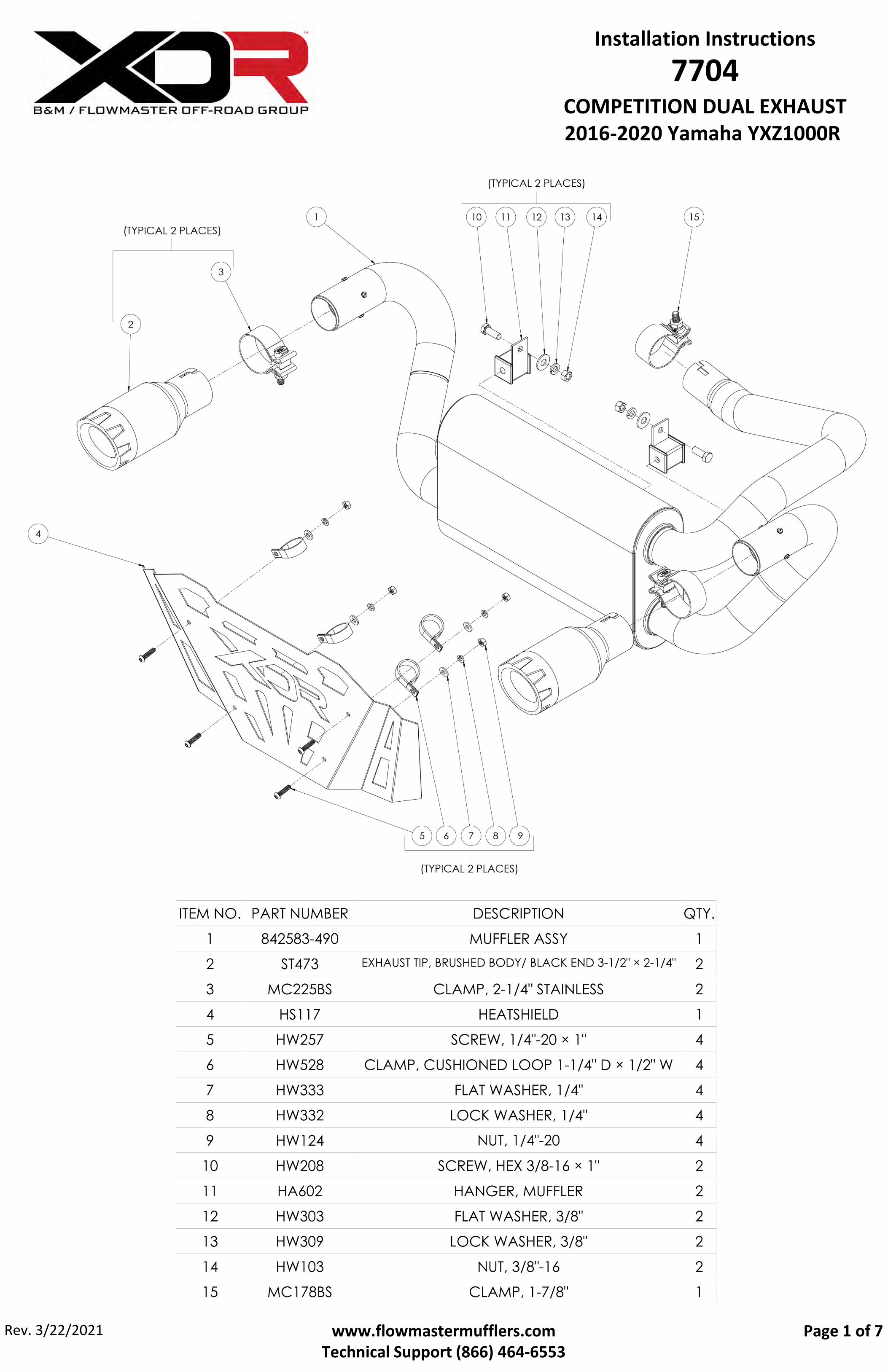
ITEM NO. PART NUMBER DESCRIPTION QTY. 1 842583-490 MUFFLER ASSY 1 2 ST473 EXHAUST TIP, BRUSHED BODY/ BLACK END 3-1/2" × 2-1/4" 2 3 MC225BS CLAMP, 2-1/4" STAINLESS 2 4 HS117 HEATSHIELD 1 5 HW257 SCREW, 1/4"-20 × 1" 4 6 HW528 CLAMP, CUSHIONED LOOP 1-1/4" D × 1/2" W 4 7 HW333 FLAT WASHER, 1/4" 4 8 HW332 LOCK WASHER, 1/4" 4 9 HW124 NUT, 1/4"-20 4 10 HW208 SCREW, HEX 3/8-16 × 1" 2 11 HA602 HANGER, MUFFLER 2 12 HW303 FLAT WASHER, 3/8" 2 13 HW309 LOCK WASHER, 3/8" 2 14 HW103 NUT, 3/8"-16 2 15 MC178BS CLAMP, 1-7/8" 1 Installation Instructions 7704 COMPETITION DUAL EXHAUST 2016-2020 Yamaha YXZ1000R www.flowmastermufflers.com Technical Support (866) 464‐6553 Page 1 of 7 Rev. 3/22/2021
Transcript of 7704 Instructions - Holley
ITEM NO. PART NUMBER DESCRIPTION QTY.
1 842583-490 MUFFLER ASSY 1
2 ST473 EXHAUST TIP, BRUSHED BODY/ BLACK END 3-1/2" × 2-1/4" 2
3 MC225BS CLAMP, 2-1/4" STAINLESS 2
4 HS117 HEATSHIELD 1
5 HW257 SCREW, 1/4"-20 × 1" 4
6 HW528 CLAMP, CUSHIONED LOOP 1-1/4" D × 1/2" W 4
7 HW333 FLAT WASHER, 1/4" 4
8 HW332 LOCK WASHER, 1/4" 4
9 HW124 NUT, 1/4"-20 4
10 HW208 SCREW, HEX 3/8-16 × 1" 2
11 HA602 HANGER, MUFFLER 2
12 HW303 FLAT WASHER, 3/8" 2
13 HW309 LOCK WASHER, 3/8" 2
14 HW103 NUT, 3/8"-16 2
15 MC178BS CLAMP, 1-7/8" 1
Installation Instructions7704
COMPETITION DUAL EXHAUST 2016-2020 Yamaha YXZ1000R
www.flowmastermufflers.comTechnical Support (866) 464‐6553
Page 1 of 7Rev. 3/22/2021
REVIEW THE INSTRUCTIONS ANDVERIFY THE KIT CONTENTS:
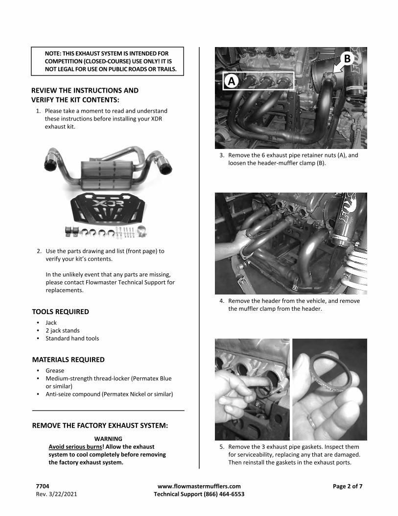
1. Please take a moment to read and understandthese instructions before installing your XDRexhaust kit.
2. Use the parts drawing and list (front page) toverify your kit’s contents.
In the unlikely event that any parts are missing,please contact Flowmaster Technical Support forreplacements.
WARNINGAvoid serious burns! Allow the exhaust system to cool completely before removing the factory exhaust system.
REMOVE THE FACTORY EXHAUST SYSTEM:
3. Remove the 6 exhaust pipe retainer nuts (A), andloosen the header‐muffler clamp (B).
B
A
4. Remove the header from the vehicle, and removethe muffler clamp from the header.
5. Remove the 3 exhaust pipe gaskets. Inspect themfor serviceability, replacing any that are damaged.Then reinstall the gaskets in the exhaust ports.
www.flowmastermufflers.com Technical Support (866) 464‐6553
Page 2 of 7
NOTE: THIS EXHAUST SYSTEM IS INTENDED FOR COMPETITION (CLOSED‐COURSE) USE ONLY! IT IS NOT LEGAL FOR USE ON PUBLIC ROADS OR TRAILS.
TOOLS REQUIRED
• Jack• 2 jack stands• Standard hand tools
MATERIALS REQUIRED
• Grease• Medium‐strength thread‐locker (Permatex Blue
or similar)• Anti‐seize compound (Permatex Nickel or similar)
7704Rev. 3/22/2021
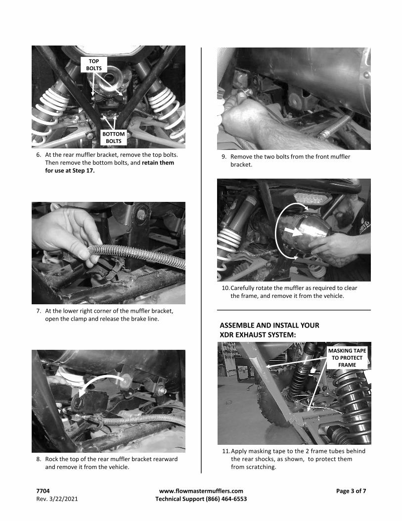
7. At the lower right corner of the muffler bracket,open the clamp and release the brake line.
8. Rock the top of the rear muffler bracket rearwardand remove it from the vehicle.
9. Remove the two bolts from the front mufflerbracket.
10.Carefully rotate the muffler as required to clearthe frame, and remove it from the vehicle.
www.flowmastermufflers.com Technical Support (866) 464‐6553
Page 3 of 7
TOP BOLTS
BOTTOM BOLTS
6. At the rear muffler bracket, remove the top bolts.Then remove the bottom bolts, and retain themfor use at Step 17.
ASSEMBLE AND INSTALL YOURXDR EXHAUST SYSTEM:
11.Apply masking tape to the 2 frame tubes behindthe rear shocks, as shown, to protect themfrom scratching.
MASKING TAPE TO PROTECT
FRAME
7704Rev. 3/22/2021
15.Assemble the hangers (11) to the muffler bracketusing screws (10) on the hanger side, and flatwashers (12), lock washers (13) and nuts (14) onthe bracket side. Leave the hardware loose atthis time.
www.flowmastermufflers.comTechnical Support (866) 464‐6553
Page 4 of 7
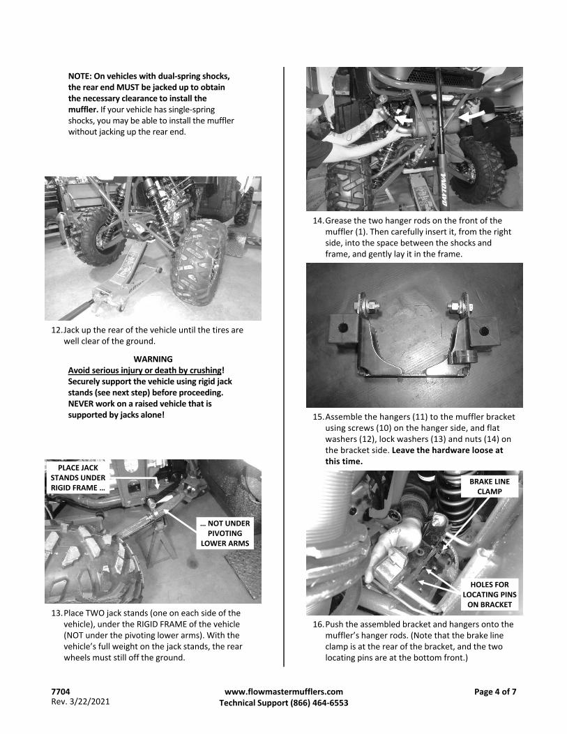
12.Jack up the rear of the vehicle until the tires arewell clear of the ground.
WARNINGAvoid serious injury or death by crushing! Securely support the vehicle using rigid jack stands (see next step) before proceeding. NEVER work on a raised vehicle that is supported by jacks alone!
NOTE: On vehicles with dual‐spring shocks, the rear end MUST be jacked up to obtain the necessary clearance to install the muffler. If your vehicle has single‐spring shocks, you may be able to install the muffler without jacking up the rear end.
13.Place TWO jack stands (one on each side of thevehicle), under the RIGID FRAME of the vehicle(NOT under the pivoting lower arms). With thevehicle’s full weight on the jack stands, the rearwheels must still off the ground.
PLACE JACK STANDS UNDER RIGID FRAME …
… NOT UNDER PIVOTING
LOWER ARMS
14.Grease the two hanger rods on the front of themuffler (1). Then carefully insert it, from the rightside, into the space between the shocks andframe, and gently lay it in the frame.
16.Push the assembled bracket and hangers onto themuffler’s hanger rods. (Note that the brake lineclamp is at the rear of the bracket, and the twolocating pins are at the bottom front.)
HOLES FOR LOCATING PINS ON BRACKET
BRAKE LINE CLAMP
7704Rev. 3/22/2021
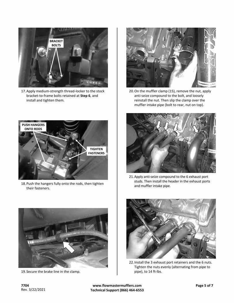
BRACKET BOLTS
17.Apply medium‐strength thread‐locker to the stockbracket‐to‐frame bolts retained at Step 6, andinstall and tighten them.
18.Push the hangers fully onto the rods, then tightentheir fasteners.
PUSH HANGERS ONTO RODS
TIGHTEN FASTENERS
19.Secure the brake line in the clamp.
www.flowmastermufflers.comTechnical Support (866) 464‐6553
Page 5 of 7
20.On the muffler clamp (15), remove the nut, applyanti‐seize compound to the bolt, and looselyreinstall the nut. Then slip the clamp over themuffler intake pipe (bolt to rear, nut on top).
22. Install the 3 exhaust port retainers and the 6 nuts.Tighten the nuts evenly (alternating from pipe topipe), to 14 ft‐lbs.
21.Apply anti‐seize compound to the 6 exhaust portstuds. Then install the header in the exhaust portsand muffler intake pipe.
7704Rev. 3/22/2021
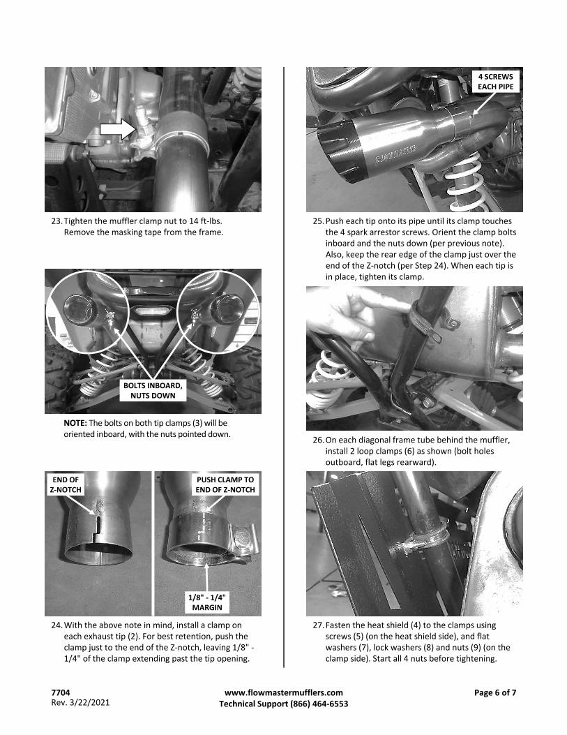
24.With the above note in mind, install a clamp oneach exhaust tip (2). For best retention, push theclamp just to the end of the Z‐notch, leaving 1/8" ‐1/4" of the clamp extending past the tip opening.
PUSH CLAMP TO END OF Z‐NOTCH
END OFZ‐NOTCH
1/8" ‐ 1/4" MARGIN
NOTE: The bolts on both tip clamps (3) will be oriented inboard, with the nuts pointed down.
BOLTS INBOARD, NUTS DOWN
www.flowmastermufflers.comTechnical Support (866) 464‐6553
Page 6 of 7
23.Tighten the muffler clamp nut to 14 ft‐lbs.Remove the masking tape from the frame.
4 SCREWSEACH PIPE
25.Push each tip onto its pipe until its clamp touchesthe 4 spark arrestor screws. Orient the clamp boltsinboard and the nuts down (per previous note).Also, keep the rear edge of the clamp just over theend of the Z‐notch (per Step 24). When each tip isin place, tighten its clamp.
26.On each diagonal frame tube behind the muffler,install 2 loop clamps (6) as shown (bolt holesoutboard, flat legs rearward).
27.Fasten the heat shield (4) to the clamps usingscrews (5) (on the heat shield side), and flatwashers (7), lock washers (8) and nuts (9) (on theclamp side). Start all 4 nuts before tightening.
7704Rev. 3/22/2021
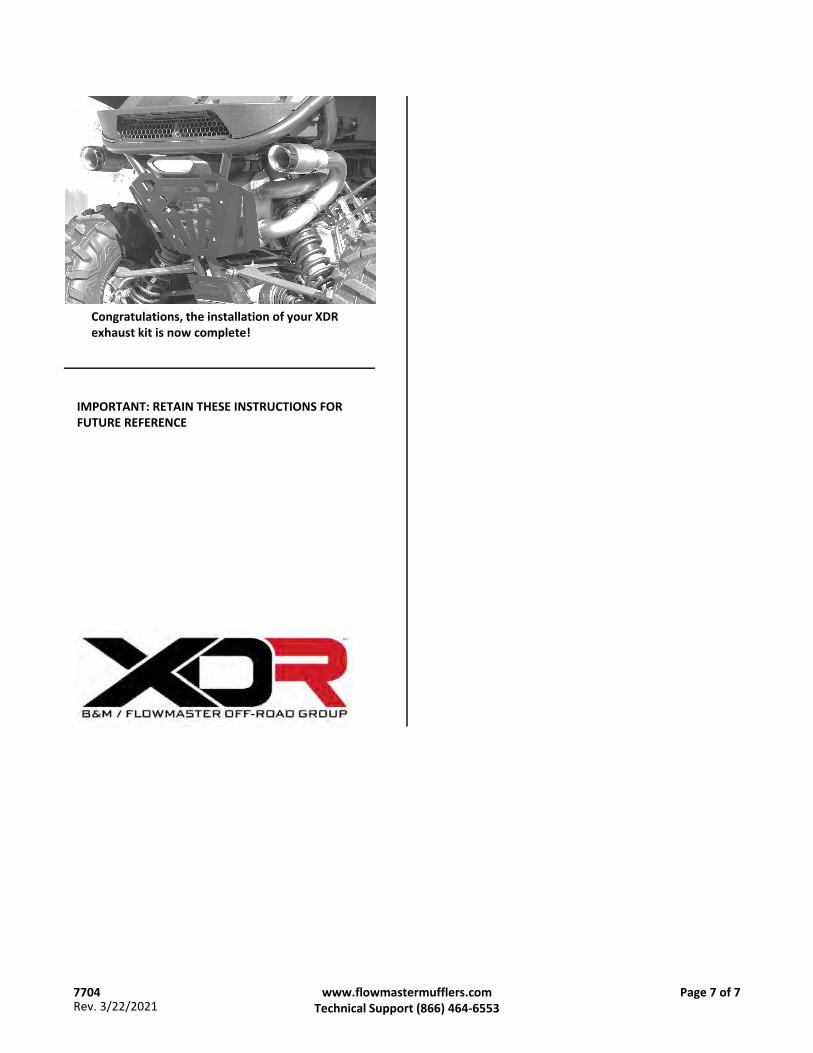
Congratulations, the installation of your XDR exhaust kit is now complete!
www.flowmastermufflers.comTechnical Support (866) 464‐6553
Page 7 of 77704Rev. 3/22/2021
IMPORTANT: RETAIN THESE INSTRUCTIONS FOR FUTURE REFERENCE
SPARK ARRESTOR MAINTENANCEfor FLOWMASTER / XDR
ATV & UTV EXHAUST SYSTEMS
Flowmaster ATV and UTV exhaust systems are equipped with US Forest Service‐qualified spark arrestors, which are designed to prevent the discharge of sparks from the exhaust pipes.
Spark arrestors must be inspected and cleaned periodically to prevent clogging and deterioration, which can adversely affect the performance of both the spark arrestor and the engine.
WARNINGAvoid serious burns! Allow the exhaust system to cool completely before inspecting the spark arrestors.
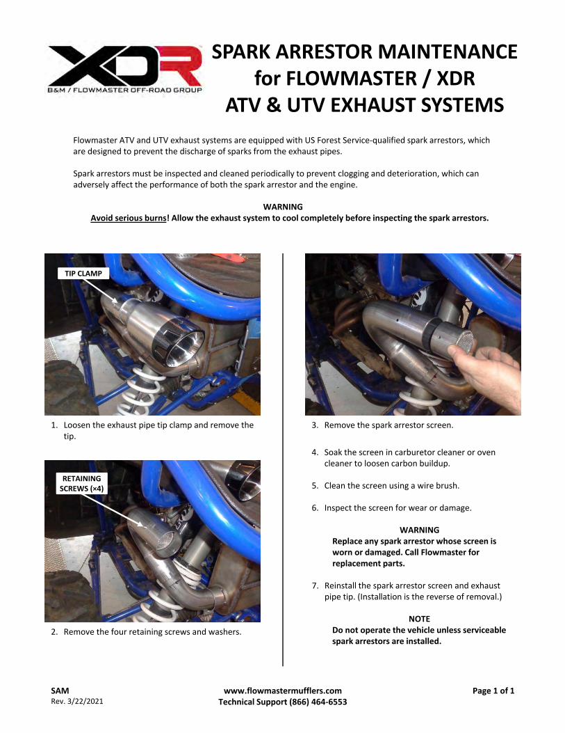
2. Remove the four retaining screws and washers.
RETAINING SCREWS (×4)
1. Loosen the exhaust pipe tip clamp and remove thetip.
TIP CLAMP
3. Remove the spark arrestor screen.
4. Soak the screen in carburetor cleaner or ovencleaner to loosen carbon buildup.
5. Clean the screen using a wire brush.
6. Inspect the screen for wear or damage.
WARNINGReplace any spark arrestor whose screen is worn or damaged. Call Flowmaster for replacement parts.
7. Reinstall the spark arrestor screen and exhaustpipe tip. (Installation is the reverse of removal.)
NOTEDo not operate the vehicle unless serviceable spark arrestors are installed.
www.flowmastermufflers.comTechnical Support (866) 464‐6553
Page 1 of 1SAMRev. 3/22/2021


![Borg EDF4 Focal Reducer [7704]](https://static.fdocuments.in/doc/165x107/613d00840c37c14a830cf614/borg-edf4-focal-reducer-7704.jpg)