77 PEEL ANGLE ON PEEL FORCE(U Ehh7hhmm - DTIC
27
77 O-RI86 117 EFFECT OF PEEL ANGLE ON PEEL FORCE(U AKRON UNIY OH I/I INST OF POLYNER SCIENCE R S MILLER OCT 97 TR-19 NS9914-95-K-9222 UNCLSSIFIE0 F/0 11/1 ML Ehh7hhmm
Transcript of 77 PEEL ANGLE ON PEEL FORCE(U Ehh7hhmm - DTIC
77O-RI86 117 EFFECT OF PEEL ANGLE ON PEEL FORCE(U AKRON UNIY OH I/I
INST OF POLYNER SCIENCE R S MILLER OCT 97 TR-19NS9914-95-K-9222
UNCLSSIFIE0 F/0 11/1 ML
Ehh7hhmm

L L.L.
~ I7 ' - *** 1 7. -- L m

r$T fL L uUPJ
DTICS C 16187D
L. L W. f*vA** % * '
SI CUR~t CI~A%5~IC TIONO7,0.0 alE1 ("In Deta l.rr..rid)
REPOT DM ENTAION AGEREAD INSTRUCTIONSREPOR DOCMENTTIONPAGEBEFORE COMiPLETINGi FORMIl No ont NUiSIR a 12oOVT ACCESSION No 111RECIPIENT'S CATALOG leUMSCO
P( finb1 , P eport No, 10 Ac p I4 #~ '.r S.,110 TYPE 011 AREPOt "T 6PEC"OD co Vaokff
'efi n1e, P Technical Report
7 AUTNO011fe) SCONTRACT ON GooAipf NumetRej
N ent and . *aqN00014-8b-K-C)22
it IERftORWIW ONGANIZATIO1N NAME AND ADONIS% Ift. PROGRAM ELK0MET.PROJELCT, TASA(
AREA 11 0009 UNIT "UM89"S. Pe o 1vmler , lence4315ti V1 vPV '~ It yt kron432/-555
Akron. Jhio 44325 IRPOTOT11CONTROLLING OFFICE NAME AND ADESI EOTDT
e () Naval Research October 1987)we,- Prnqrarr IS NU111111ROF PAGES
i ~ n,.A 2:'-uO224 MOINI T ONING AG9NCY N AMC & ADRESfjjqI diltanim free, ComnteiUlmj 0
1,9e) IS SECURITY CLASS. (of Ifte eoopeeV,
JnclassifiedI~a. DIECL ASSI PICA 7,004/00101GRADING
SCHEDULE
is -. TRIDUTION STATEMENT (of ifle j*pept)
-4 'n t itat ed distribution li st.-4 r )vod for iowil 1( release, distribution ur ,,tricted.
11 OSTRIOUT ION ST ATEMENWT (of she abopproal amerd On. SeCk 20. it dUierent ho Rspoof)
10 SUPPLEWSN VARY NOTES
,j1'itod f or Purl ication in: Journal of A,-'0sion
It. ItEY SOROS (Compose en roeese aide it wmoogosr -o Idemf99op Wee number)
Adhesion, Adhesives, Bending, Detachment, Fra ture energy, Fracturenecnani-s, Pe-1 angle, Peeling, Separation, Strength
20 *1 PACT f(emeD...we an roovee side It neorceee and Ident9ity0 by,6091 numwber)
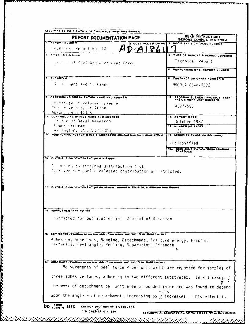
Measurements of peel force P per unit width are reported for samples of
three adhesive tapes, adhering to two different substrates. In all cases
the work of detachment per unit area of bonded interface was found to depend
upon the angle ) f detachment, increasing as , increases. This effect is
*DD ,.',, 1473 to09- IOF NOV IS$ IS OBSOLETE
P/ 0; fr1LF- Old4- 6601 SECURITY CLASSIFICAToONi OF THIS PAGE (loo Data IaLmWed)

"C OT CLASSIFICATION or THIS PAG1 (Whe Does "00le o
attributed to dissipation of energy in bending the tape away from the
F substrate at the line of detachment, to a greater degree as , Increases.*" .rl
Extrapolation to P = 0 is suggested as a simple way of minimizing ortrl-
butions to the observed work of detachment that arise from hendinq an
imDerfectly-elastic adhering layer as it is peeled away from a flat ,1i,;Id
substrate. But at small peel angles the tape tends to stretch ap;)rpciahl .
16. Peeling at 45 is recommended to minimize both effects.
NTIS ORA&&L MDYIC TAR 1
[-y
Jut1 Aoaot~ Isel
DItrIbu tieWAvsliabL Ity Code
-fi-t Speoial
IN 0102- LF. 014- 6601
SECURITY CLASSIFICATION or
THIS PAGIE(WheK Dai. fnrIteed)
+'.% p'. '. ..' . • 2 -2 .' -.'. 'w _ ..- ., '. , . ' .'-. ..' -- . -. ... . -. .-. -. .. .. . . . . .. . . .

. JV
1 . Introduction
The peel test is comonly used to determine the strngth
of an adhesive joint (1-6). Scientifically, it has two
distinct advantages compared to other test methods: bond
tailur, proceeds at a controlled rate, and the peel for,,e is
a direct measure of the work of detachment 17-10) . From t
practical viewpoint, the peel test is valuable because it is
simple to carry out and because it represents a mode o)t
tallure under service conditions, e.g. , for adhesive tapes.
However , variations in the way the test is carried out; i n
particular, variations in the' anqle _ at which the adhering
layer is detached, hav. been : ound to give quite dif ferent
valus tor the work of de tachment isee refs. 2 and I I, for
example, and the_ results given be 1ow)
This anomalous be:havlor has been attributed to changes
ini the dlistr ibution )f tons .e stress s,.t up in the interface.
on pee-l ing at various angles, represented by an angle-
dependent stress factor K (11). Alternatively, it has been
attributed to a change in the mode of failure, from primarily
shear failure at small peel angles to primarily tensile
failure at large anqles (2). Neither of these explanations
seem fully acceptable; the former because within the limita-
tions of stress analysis the factor K can be shown to be
necessarily close to unity at all angles of peel (12) , and
the latter because failure of soft elastic solids under
applied shear forces is commonly found to take place by
tensile rupture, under the action of the major tensile stress
p°
EI.. . , i[

t ht work o t detj 'ihmen-t is t bouqht t(,j i t - z, iZl '0'!
.'Xemridtd i r rev-z si l 1 ,,, I) n n b d 1 i ; t ti i .d her 1 t~ i, a r aw,
I 2, 1 - I T~V - , a~d it o 1w-rk w,, I en eat r it .it1-
I L~1 s t',eWI- t ht' i W1t 1 Wi be SlIb I',wt i'd t :More
1:,rde t.i Lotr ate the, possiblt maqritude, )t the,
r 1 r iut 1 1. 'r11ht bend inq n tgy *(ej' 1s s t u t het o bs er,.e d
-)I~ nit,* som' xperime-ntal rt-suIt s are. qiv.en here ts) r t ir ee
* rnm I, i Ii Adh-s iv. t tpes pt-t- led tway t rom r i q id subs tratoes
a t .,ir 1 wus ile';I -s. Ai , x t rap)Ila t ion proc'tdu re i s t her,
iwe i-t'trri :,i n q the w o L detachment in the
*tbe'v~di~s enrs uO~S Ih 'ut s a re alIsoc
* mii I .d1 wt h t ms. jta'1Ttd by o-thte!r 2thods, which rorre-
spod pt-t Iiirg dtl'-hnlent it luw peel inqles, or with ,only
s ma I ilwi~ti mi straiins set up in, the- detachling strI-p.
2 'he rt alcon s i dera t ion s
V' peel torc- P pe-,r u n it w id th o-)f a de t1-c h1ng4 s tr Ip
pro)vidfes A COntinUOUS measure of the worK G,- oxpne in
detachment per unit of bonded area. The re-lation between P
.iod (-;a isnt q-nera-lly a simple one, however, It can be
dIerived from einorqy considerations, as follows.
Consider growth of the debond by a distance c (Figure 1).
The distance d travelled by the force P in its own direction
is given by
%'

.4
d = c(l + e - cos-) I)
from geometrical considerations, Figure 1, where u is t:,.
fractional elongation of the detached strip under the petl
force P and - is the peel angle. Thus, the energy I- lanc-
becomes (10):
P(l + e - c (U + Ga ) (2)
where U denotes the energy expended per unit length in
stretching the strip to an elongation e. (Note that it has
not been assumed that the deformation process is a linear or
an elastic one up to this point.)
We now make the simplifying assumption that the relation
between the stretching force P and corresponding extension e
%is a linear one, with a slope, i.e., tensile stiffness of
the adhering layer, of K, so that
U = P2/2K. (3)
Equation (2) then becomes:
Ga = P(l - cos.) + (P2 /2K) (4)
The second term, denoted .Ga hereafter, on the right-hand
side of equation 4 is negligibly small when e I - cos
in the kexperiments described below,carried out with three
commercial adhesive tapes, this condition was satisfied for
values of peel angle of 450 or greater. Thus, for rela-
tively inextensible tapes or for peel angles greater than
about 45', the work of detachment is given by
Ga P( - cos) (5)
to a good approximation. If the work Ga of detachment is a
property of the bond and independent of the way in which
VU-
"' ' " " ' ' -'' ' - ." "" " -' ". " -"" "" ' ' ." .. . " ' . ' "" ' . " • ' . " ,

i* tacnmen t is r:tt - t, r ,- w u J t x
tiD be inversei y pr i%,rtlna1 t. - :'5 I.. :, " -
s ar e .- iuA rtt , t _ t 1y.
Th.hr,., comm.r:L. t.-s1,. t ies were used 1n tne exermet
A, a v:nyl-oacKed . tri: i1 tpe t3M Scotch brand No. 88), B, anctn.-:r
similar tape (3M Scotmn brand No. 35), and C, a window mounting ta
A'ith a stiff plasL I: nacking 13M Catalog No. 2145). Because of the
different elastic moduli of tre materials used as backings the
three tapes had juite different stitfnesses K in tension: about
3.5 kN m for tapes A and B and about 85 kN/m for tape C, per unit
width of tape (16). They were applied t- two flat rigid sub-
strates; a 4lass p'.te and a Teflon pla, ; and peeled off about
15 min later at various angles in such vay that the line of
detachment advanced at a constant rate o: 0.17 mm/s.
Tn order to reduce the amount of ben-Jmng at the line of
detacnment some experiments were carried ut with tape C as
shown schematically in Figure 2, the tap being peeled off
around a steel roller having a diameter 12.7 mm. The tape
was backed with a strip of 3M Scotch bra: Magic transparent
tape, Catalog No. 119, in these expermmer.-s, to prevent it
Ad.hrinq to the roller. The additional Lacking layer was
found not to affect the peel strength of tape C, in other
experiments. Weights were added to the roller in order to
pull the ta~e into conformity with it at the line of detach-
ment from the substrate. Values of the work of detachment
Ga were calculated in these cases from the relation:

6
Ga = 2P - W (6)
where P is the peel force per unit width of tape and W is
the weight of the roller plus any added weights. In no case
was the total force P sufficiently large in the experiments
with a roller to cause a significant extension of the tape.
All of the experiments were carried out at ambient
temperature, about 240 C.
4. Experimental results
Values of the detachment energy Ga for tapes B and C
adhering to a glass substrate are plotted against the peel
angle - in Figure 3. They are seen to depend strongly upon
the peel angle, especially at large angles, rising from
about 70 Jim 2 to about 230 J/m 2 for tap- R and from about 240
JIm 2 to about 700 J/m2 for tape C as th peel angle was
increased from small values to 1800. Similar results were
obtained with a Teflon substrate, as shown in Figure 4,
although the values of Ga were much smaller in this case:
40 - 140 J/m2 for tape A and 35 - 90 J/m 2 for tape C.
Resuits obtained by peeling tape C away from a glass
substrate around a rigid roller are shown in Figure 5. When
the total weight was increased from the small weight of the
roller itself, the detachment energy was found to decrease
substantially, tending towards an asymptotic value of about
270 J'rn2 at large added weights, i.e., when the tape was
forced to conform to the gentle curvature of the roller and
the degree of bending was minimized. Thus, when the tape was
v '.-.-.' . . ." " " . ...................................... - • • .. ... .. .. v ' .. ' ' . .

.7
subjected to only slight bending during detachment, either
by employing small peel angles or by peeling around a roller,
then the work of detachment was relatively low. When the
tape underwent severe bending, then the work of detachment
was high.
A quantitative comparison of the values obtained for
Ga under various test conditions is given in Table 1. In
all cases, the work of detachment at 1800 was found to be
about three times as large as that at low peel angles. When V
peeling of tape C was carried out at 1800 around a roller, %
however, then the work of detachment was reduced to the same
value as at 00. Thus, the degree of bending imposed on the
peeling strip is a major factor in determining the magnitude
of the work of detachment, as surmised )reviously (12, 15-17).
It is responsible for large changes in the observed value as
the peel angle is increased.
In order to remove the contribution of bending energy
losses to the observed peel strength it seems advisable to
adopt one of two measures. Either the peel angle should be
chosen to be relatively small; say, 450; or peeling should
be carried out using a roller to minimize the curvature of
the peeled strip. This latter condition is not easily
achieved, however, because the local curvature at the line*5%.5.
of detachment is not necessarily equal to that of the roller5%
unless the tape is forced to conform. And when large forces
are applied to the tape, additional work Ga may be expended -.
in stretching it, equation 4, and must be taken into account. a-
-k"%.
~ I~~-~Y2- !
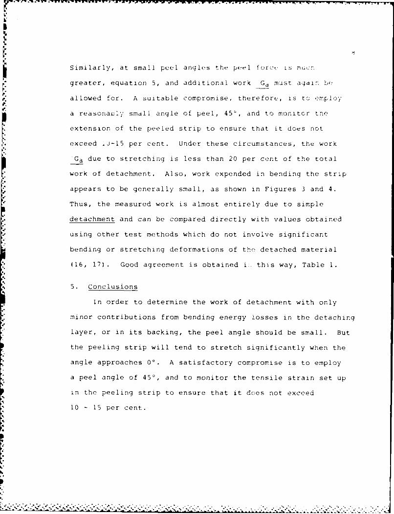
Similarly, at small peel angles the peel force is mucr
greater, equation 5, and additional work Ga must agai. be
allowed for. A suitable compromise, therefore, is to employ
a reasonauly small angle of peel, 45', and to monitor the
extension of the peeled strip to ensure that it does not
exceed .'-15 per cent. Under these circumstances, the work
Ga due to stretching is less than 20 per cent of the total
work of detachment. Also, work expended in bending the strip
appears to be generally small, as shown in Figures 3 and 4.
Thus, the measured work is almost entirely due to simple
detachment and can be compared directly with values obtained
using other test methods which do not involve significant
bending or stretching deformations of the detached material
(16, 17). Good agreement is obtained i:. this way, Table 1.
5. Conclusions
In order to determine the work of detachment with only
minor contributions from bending energy losses in the detaching
layer, or in its backing, the peel angle should be small. But
the peeling strip will tend to stretch significantly when the
angle approaches 00. A satisfactory compromise is to employ
a peel angle of 450, and to monitor the tensile strain set up
in the peeling strip to ensure that it does not exceed
10 - 15 per cent.
5%5%

.. ... . , . . = .. . . . ' ] 1 ) , ' I , ,4 1 4., -,
.114 1
_____5 , 14, 4i ;. P. 5. Riv .. , PAl,.t "!'.:o ., 9, HI5 Ki 441 .
8. T. Hata, Kobunsk1 KagaKu, 4, 67 (194 .
9. B. V. D ryagin nd N. A. Krot 7, Dot.kad',' Akad. N~u.
SSSR., 61, 849 (2948).
I0. P. B. LindItiy, J. Instn. Pubber Jdustry , 5, 24 I' .
I . D. H. Kaelbie and C. L. Ho, Trans. Soc. Rheol., 18,
(1974).
12. A. N. Gt,.nt and G. R. Hamed, J. AdI. sion, i, I
13. W. G. Knauss, Int. J. Fract. Mech., 6, 183 (1<-)
14. A. Ahagon, A. N. GCfnt, H. J. Kim and Y. Kimaga, PuLL.
Chem. Tychnol., 48, 896 (1975).
15. A. N. Gent and G. P. Ham d, Zj. p .i r I .
2817 (1977).
16. A. N. Gent and S. Kaan r, . Appl. _I : 1j'm r S:i.. , , 46 1
(2986 I
l . A. N. G,,.nt And .. .. . I.,w< d'j(w..<:', " ".'i k" :_ P ; ' '_ :
" ' - , " , ' ' '." ' . ' - - ", - . " . . . . ' . , " . --.. -,' ."4 .'- - " • " "' , . " . . -

-'S 10
%Table 1: Values of the work Ga of detachment under
% different test conditions.
Ga 18O0 ) Ga (small _
Ga(-=0o)a Ga(-9O0 ) Ga(--l 8O0 ) using a roller (16, 17)
(j/m2) (Jim 2) (ji/M 2 (J/m 2 ) (m 2)
* - ~ape
-n glass 50 80 150 34
T- ie B
Crn glass 70 110 230----
-~ass 240 20700 20215
>-l r. 43 74138 36-
*T38 47 98 17
T~in 748 86 34
~ ~t ~ a~lati%
Figure Captions
Figure 1: Mechanics of peeling
Figure 2: Peeling around a weighted rol> :
force and W is the weight of tht, r: .
added weights, per unit width cr -jL,
Figure 3: Work Ga of detachment vs peel in.[e :r t -
and C adhering to glass
Figure 4: Work Ga of detachment vs pe _,. ang :.
and C adhering to Teflon
FIgure 5: Work Ga of detachment of ta. 7:-o= . ,
peeled otf around a weighted : lr A.
weight W per unit width of tau

N p
//
//
N
-N
tPNj
0/(~D/
%%% . .

13
SW/2
* ***4' D , ..* * IW. -v. /. *.2.

14
800
600-
Go!(O/m2 ) .
Tape C k
400.
200 -.
- [::}Tape B
0 90 180Peel Angle (Degrees)
Figure 3.
am--{ , 'i-l w;- ti " l- - i ] ] m m • ii

U
150 "l
100- Tape A,/ni
(j~()
50-
-- II
IO0Tap -Cap
03
0 90 180Pee IAngle (Degrees)
Figure 4,
-q ." ,;,; ', - a2;, ',.', . ; .-..-. , " ' -..- . - - . ..

16
500
400
300- A A AAA
G.300
(J/m)200-
100-
00 I 2
W (kN/m)
ur .- "
--.. ', .:.',..-.v :, .,,.;.-.- . . ;.. , . ? -h. .L . ... , , .: . . - .-. .. ,.. . . ..-. .. , .;,.

Ser 43-, /2 >:
Revised January 17
(DYN)DISTRIBUTION LIST
Dr. R.S. Miller Dr. L.V. Schmidt
Office of Naval Research Office of Naval TechnologyCode 432P Code 07CTArlington, VA 22217 Arlington, VA 22217(10 copies)
Dr. J. Pastine JHU Applied Physics LaboratoryNaval Sea Systems Command ATTN: CPIA (Mr. T.W. Christian)
Code 06R Johns Hopkins Rd.Washington, DC 20362 Laurel, MD 20707
.4
Dr. Kenneth D. HartmanHercules Aerospace Division Dr. R. McGuire
Hercules Incorporated Lawrence Livermore Laboratory
Alleghany Ballistic Lab University of CaliforniaP.O. Box 210 Code L-324
Cumberland, MD 20502 Livermore, CA 94550
Mr. Otto K. Heiney P.A. MillerAFATL-DLJG 736 Leavenworth Street, #6Elgin AFB, FL 32542 San Francisco, CA 94109
Dr. Merrill K. King Dr. W. MonizAtlantic Research Corp. Naval Research Lab.5390 Cherokee Avenue Code 6120Alexandria, VA 22312 Washington, DC 20375
Dr. R.L. Lou Dr. K.F. MuellerAerojet Strategic Propulsion Co. Naval Surface Weapons CenterBldg. 05025 - Dept 5400 - MS 167 Code R11
P.O. Box 15699C White OakSacramenta, CA 95813 Silver Spring, MD 20910
Dr. R. Olsen Prof. M. NicolAerojet Strategic Propulsion Co. Dept. of Chemistry & Biochemistry e
Bldg. 05025 - Dept 5400 - MS 167 University of California
P.O. Box 15699C Los Angeles, CA 90024Sacramento, CA 95813
Mr. L. RoslundDr. Randy Peters Naval Surface Weapons CenterAerojet Strategic Propulsion Co. Code RIOC
Bldg. 05025 - Dept 5-40 - S h Tite Oak, 5ilver Spring, MDP.O. Box 1569QC :
Sacramento, CA q5813 Dr. David C. SaylesBallistic Missile Defense
Dr. D. Mann Advanced Technology CenterU.S. Army Research ,'tice P.O. Box "5fi0Fngineering ?i.islon Huntsville. Al. 'VS07Box 12211Research Triangle Park, - " -
" ";" ; "' < " ; ; * '.i " i * < '.""" : ",: :".':"," <",: " ' ," ". v ..-.-.-- ,-, " ." " .-..'1

Revised January 1935 18
(DYN)
DISTRIBUTION LIST
Mr. R. Geisler Director
ATTN: DYiMS-24 US Army Ballistic Research Lab.
AFRPL ATTN: DRXBR-IBD
Edwards AFB, CA 93-2' Aberdeen Proving Ground, ,M 21Q35
Commander
Naval Air Systems Command US Army Missile Command
A17N: Mr. Bertram P. Sobers ATTN: DRSMI-RKL
NAVAIR-320G Walter W, ,harton
Jefferson Plaza 1, RIM 472 Redstone Arsenal, AL 35898
Washington, DC 20361Dr. Ingo W. May
R.B. Steele Army Ballistic Research Lab.
Aerojet Strategic Propulsion Co. ARRADCOM
P.O. Box 15699C Code DRXBR - IBD
Sacramento, CA 95813 Aberdeen Proving Ground, 'M 210(5
Dr. E. Zimet
Mr. M. Stosz Office of Naval Technology
Naval Surface Weapons Center Code 071
Code RIOB Arlington, VA 22217
White Oak
Silver Spring, MD 20910 Dr. Ronald L. DerrNaval Weapons Center
Mr. E.S. Sutton Code 389
Thiokol Corporation China Lake, CA 93555Elkton Division
P.O. Box 241 T. Boggs
Elkton, MD 2192t Naval Weapons CenterCode 389
Dr. Grant Thompson China Lake, CA 93555
Morton Thiokol, Inc.
Wasatch Division Lee C. Estabrook, P.E.
MS 240 P.O. Box 524 Morton Thiokol, Inc.
Brigham City., UT 8g302 P.O. Box 30058
Shrevepoit, Louisiana 71130Dr. R.S. Valentini
United Technologies Chemical Systems Dr. I.R. West
P.O. Box 50015 Morton Thiokol, rnc.
San Jose, CA 95150-0015 P.O. Box 30058Shreveport, Louisiana 7'130
Dr. R.F. Walker
Chief, Energetic Materials Divi .un Dr. D.D. DillehayDRSMC-LCE (D), B-3022 Morton Thiokol, Inc.
USA ARDC Longhorn Division
Dover, NJ 0'801 Marshall, TX 7567n
Dr. ;anet Wall (.T. BowmanCode 012 Atlantic Research Corp.
nirector, Research Admtnistrat',n 7511 Wellington Road
Naval Postgraduate ;chool ralnesvtlle, VA 22065
Monterey, CA 91
'f W.

Ser 432/84/211':y;Revised January i975 19
(DYN)
DISTRIBUTION LIST
R.E. Shenton Brian WheatleyAtlantic Research Corp. Atlantic Research Corp.7511 Wellington Road 7511 Wellington RoadGainesville, VA 22065 Gainesville, VA 22065
Mike Barnes Mr. G. EdwardsAtlantic Research Corp. Naval Sea Systems Command7511 Wellington Road Code 62R32Gainesville, VA 22065 Washington, DC 20362
Dr. Lionel Dickinson C. DickinsonNaval Explosive Ordinance Naval Surface Weapons CenterDisposal Tech. Center White Oak, Code R-13Code D Silver Spring, MD 20910Indian Head, MD 20340 %
Prof. J.T. Dickinson Prof. John DeutchWashington State University MITDept. of Physics 4 Department of ChemistryPullman, WA 99164-2814 Cambridge, MA 02139
M.H. Miles Dr. E.H. deButtsDept. of Physics Hercules Aerospace Co.Washington State University P.O. Box 27408Pullman, WA 99164-2814 Salt Lake City, UT 84127
Dr. T.F. Davidson David A. FlaniganVice President, Technical Director, Advanced TechnologyMorton Thiokol, Inc. Morton Thiokol, Inc.Aerospdce Group Aerospace Group3340 Airport Rd. 3340 Airport Rd.Ogden, UT 84405 Ogden, UT 84405
Mr. J. Consaga Dr. L.H. CavenyNaval Surface Weapons Center Air Force Office of ScientificCode R-16 ResearchIndian Head, MD 20640 Directorate of Aerospace Sciences
Bolling Air Force BaseNaval Sea Systems Command Washington, DC 20332ATTN: Mr. Charles M. Christensen
NAVSEA-62R2 W.G. RogerCrystal Plaza, Bldg. 6, Rm 806 Code 5253Washington, DC 20362 Naval Ordance Station
Indian Head, MD 20640
Mr. R. Beauregard Dr. Donald L. BallNaval Sea Systems Command Air Force Office of ScientificSEA 64E ResearchWashington, DC 20362 Directorate of Chemical &
Atmospheric Sciences
Bolling Air Force BaseWashington, DC 20332
,e .C~~eZ .j~, .. o~o # € ,-e,..-,€ .• ., .. , . ,,. -_ . - . -- .- .. " .. ' '-..'_ . -" .. .t*" ". * "~ .," '

Rev ised Ja uar ,, 1 20
(DYN)DISTRIBUTION LIST
Dr. Anthony J. M-atuszko Dr. H.G. AdolphAir Force Office of Scientific Research Naval Surface Weapons CenterDirectorate of Chemical & Atmospheric Code R11Sciences White OakBolling Air Force Base Silver Spring, MD 20qi0Washington, DC 20332
Dr. Michael Chaykovsky U.S. Army Research OfficeNaval Surface Weapons Center Chemical & Biological SciencesCode R11 Division
" White Oak P.O. Box 12211Silver Spring, MD 20910 Research Triangle Park, NC 27709
J.J. Rocchio Dr. John S. Wilkes, Jr.USA Ballistic Research Lab. FJSRL/NCAberdeen Proving Ground, MD 21005-5066 USAF Academy, CO 80840
Dr. H. RosenwisserAIR-320RNaval Air Systems CommandWashington, DC 20361
B. Swanson Dr. Joyce J. KaufmanINC-4 MS C-346 The Johns Hopkins UniversityLos Alamos National Laboratory Department of ChemistryLos Alamos, New Mexico 87545 Baltimore, MD 21218
Dr. James T. Bryant Dr. A. NielsenNaval Weapons Center Naval Weapons CenterCode 3205B Code 385China Lake, CA 93555 China Lake, CA 93555
Dr. L. Rothstein
Assistant Director
Naval Explosives Dev. Engineering Dept.Naval Weapons StationYorktown, VA 23691
Dr. M.J. KamletNaval Surface Weapons CenterCode R11White Oak, Silver Spring, MD 20910
Dr. Henry Webster, IIIManager, Chemical Sciences BranchATTN: Code 5063Crane, IN 47522
Dr. A.L. SlafkoskyScientific AdvisorCommandant of the Marine CorpsCode RD-iWashington, DC 20380
"---"-

Ser 432/84/340 21Revised January 19%5
(DYN)
DISTRIBUTION LIST
K.D. Pae Prof. Edward PriceHigh Pressure Materials Research Lab. Georgia Institute of Tech.Rutgers University School of Aerospace EngineeringP.O. Box 909 Atlanta, CA 30332Piscataway, NJ 08854
J.A. BirkettDr. John K. Dienes Naval Ordnance StationT-3, B216 Code 5253KLos Alamos National Lab. Indian Head, MD 20640P.O. Box 1663Los Alamos, NM 87544
Prof. R.W. ArmstrongUniversity of Maryland
A.N. Gent Dept. of Mechanical EngineeringInstitute Polymer Science College Park, MD 20742University of AkronAkron, OH 44325
Herb RichterDr. D.A. Shockey Code 385SRI International Naval Weapons Center333 Ravenswood Ave. China Lake, CA 93555 r
Menlo Park, CA 94025
J.T. RosenbergDr. R.B. K~use SRI InternationalMorton Thiokol, Inc. 333 Ravenswood Ave.Huntsville Division Menlo Park, CA 94025Huntsville, AL 35807-7501
G.A. ZimmermanG. Butcher Aeroject Tactical SystemsHercules, Inc. P.O. Box 13400P.O. Box 98 Sacramento, CA 95813Magna, UT 84044
Prof. Kenneth KuoW. Waesche Pennsylvania State UniversityAtlantic Research Corp. Dept. of Mechanical Engineering7511 Wellington Road University Park, PA 16802Gainesville, VA 22065
T.L. Boggs
Dr. R. Bernecker Naval Weapons CenterNaval Surface Weapons Center Code 3891Code R13 China Lake, CA 93555White OakSilver Spring, MD 20910
7cr - ' . " - . -
(DYN)
DISTRIBUT:'" Q S1T
J.M. Culver
Dr. C.S. Coffey Strategic Systems ?ro'ects ::Ice
Naval Surface .;eapons Center SSPO/SP-2T- I
Code R13 Crystal Mall ;3,?Y!C48
White Oak Washington, 'C >376
Silver Spring, M 20910
Prof. G.D. Duvall
D. Curran .ashington State niversit:
SRI International Department of Physics
333 Ravenswood Avenue Pullman, WA 99763
Menlo Park, CA 94025
Dr. E. Martin
E.L. Throckmorton Naval Weapons Center
Code SP-2731 Code 3858
Strategic Systems Program Office China Lake, CA 93555
Crystal Mall #3, RM 1048
Washington, DC 23076
Dr. M. Farber135 W. iple Avenue
R.G. Rosemeier Monnov:., CA 91016
Brimrose Corporation
7720 Belair Road
Baltimore, MD 20742 W.L. E" in
Naval Surface Weapons Center
White Oak, Bldg. 343
Silver Spring, D 1C910
C. GotzmerNaval Surface Weapons Center Defense Technical information Center
Code R-a Bldg. 5, Cameron Station
hi9e OakAlexandr i , .A 22314Silver Spring, 'D 20910 (i2 copI)
A. L Dr. Rob- PolvaniNationa- 7ureau of Standards
3251 Hanover Street Metallurcv Division
B204 Lockheed Palo Alto Research Lab Washingtn, D.C. 20234
Palto Alto, CA 94304
Di rectorR.A. Schapery
Civil Engineering Department Naval Research Kaboratory
Texas A&M University Attn: (-rje 262-
College Station, TX 77843 P'"(' DC -0375
(6 copies)
Dr. Y. Gupta Administrative ContractingWashington State University Officer (see cntract for
Department of Physics address)
Pullman, WA 99163 (1 copy)
I.%

- - V. - '.~ d'~ - 'J~ ~ S~ .%.% - -. *."~ %-.~ ~ ~ V. E-.
4,
4 * .4"
4 'V4
.4'
* 44'
U '.4
'.4
I4~I
4~1
A
* I.4.
4. .4..4, .4.
4-
- 4%
-. .4..4 .4.
.4.
.4
.4
V.
4.
'4
44 4*'
.4
'4
.4
4..
.4,
4.'4
.4
.4 .4.
.4
4.
.4 .4'.4 .4
-4
4'
2-. .14,4 .I
. . . 4.....,
4-- ---. 4.----U