
Evening Hearld_1946 … · — *9 iSIanrtT^atpr Ett^ttittg Hfmlh lout Town M rraManta

NASA CR-
I /+&&77 02-118544-2 L
D M I C DoCKING TEST SYSTEM (DDTS) ACTIVE TABLE COMPUTER P R O G M
NASA ADVANCED DOCKING SYSTM (WADS)
https://ntrs.nasa.gov/search.jsp?R=19740026177 2018-06-02T00:36:32+00:00Z

DOCUMENT NO. D2-118544-2
DYNAMIC DOCKING TEST SYSTEM (DOTS) ACTIVE TABLE COMPUTER PROGRAM NASA ADVANCED DOCKING SYSTEM
i W S 1
Contract NkS 9-13136
August 30, 1974
Prepared by
R. M. Gates R. E. Jantz
Approved by
Technical Program Manager
BOEING ~EROSPACE CDWPANY
- Houston, Texas

DATE APPROVED

This document describes the computer program developed t o describe t h e .
three-dimensional motion of the Dynami c Docking Tes t System (DDTS) ac t ive table. The input cons is ts of i n e r t i a and geometry data , , ac tuator struc- t u r z l da ta , forcing function data , hydraulics da ta , servo e lec t ronics da ta , and in tegra t ion control data. The output cons is ts of t a b l e responses,
actuator bending responses, and ac tua to r responses.
ABSTRACT
KEY WORDS
Docking Simulator
Dynani c Doc k3 ng Tes t Sys tern (DDTS) Hydraulic Actuator
Mathematical Model Motion' Simulator
iii

TABLE OF CONTENTS
PARAGRAPH PAG E - REVISIONS
, - ABSTRACT AND KEY WORDS
TABLE OF CONTENTS
- L I S T OF ILLUSTRATIONS -
REFERENCE
1.0 GENERAL INFORMATION 1.1 ,COMPUTER SYSTEM 1.2 ; PURPOSE 1.3 ' LIMITATIONS
2.0 PROCEDURE 2.1 PROGRAM NAME 2.2 NOMENCLATURE 2.3 METHOD
.d.O I NPUT/OUTPUT DESCRIPTION 3.1 . INPUT DESCRIPTION AND PREPARATICN 3.2 OUTPUT DESCRIPTION 3.3 ERROR MESSAGES
4.0 OPERATING INFORMATION 4.1 PROGRM 'AND DATA SETUP 4.2 RUN INFORMATION
5.0 PROGRAMING - INFORMATION . - 5.1 FLOW CHARTS 5.2 SYSTEM STRUCTURE ..
5.3 LIBRARY SUBROUTINES 5.4 PROGRAM LISTING 5.5 SAMPLE PROBLEM

ILLUSTRATIONS
FIGURE
,. 1 DDTS Simulator Faci 1 i ty
Actfve Table Coordinate Systems ~ .
Mass Mztrix
Servo ~lectroni cs Block Diagram
PAGE -

-
REFERENCE
Boeing ~ocument 02-118544-1, "Mathematical Model for the Simulation o f
Dynamic Docking Test System Active Table Motfon ," -August 30, 1974. \

1
1 r;
D2-110544-2 ! -~ - . - I 7
1 _ - 1.0 GENERAL INFORMATION
-- 1 .l COMPUTER SYSTEM r -
- - -. This program was written i n FORTRAN V language for use on the UNIVAC 1108 '
I- I
computer w i t h the EXEC I1 operating system. -The program can easily be , -.
. - converted t o the EXEC 8 operating system. The plotted output i s done on . - the Stromberg Datagr-aphix's SD-4060 m i crofi l m plotter. 1
i r
i 1 . 1.2 PURPOSE !
The program simulates the motions of the NASA JSC Dynamic Docking Test i - i
System (DDTS) active table. Given a description of the table mass and
geometry, the actuators, the hydraulic sys tem , the electronics, and the !
forcing function, the program outputs time-histories of table responses, I I actuator bending data, and actuator responses. Responses t o the f 01 1 owi ng I ! i
I i n p u t forcing functions are calculated: ' i i I i a. Step velocity comnand t I
b. Si nusoidal position commands
c. Step external 'forth: on table c,g. d. Si r~usoidal external force on tab1 e,. c,g .
1.3 LIMITATIONS
Forcing functions are limited t o those l i s ted in Paragraph 1.2. Dynamics ' I - ,
1 of the, simulator due to docking are .not modeled. Actuator control system 1 I
i components are limi,ted to those shown i n Figure 4. In the actual DDTS, 1 : * 1 L
~ - there are notch f i l t e r s i n both the velocity command l ine and the forward
t loop which are not included i n th i s simulation. I
2.0 PROCEDURE
2.1 FROGRAEl NAME
The program acronym i s NADS , .
from - NASA Yvanced b c k i n g System. - -

- 2.2 NOMENCLATURE
Program - A
A A
AL
ALPHA
AL3D
AV
BETA
BETAE
CAA
CAL
' DLTAI
Engineering
MI
A1' A2
it P
1 P
a
'4' .P -
'P B
fje
B p \
- I
.. c
1 c
c
C~
AX, Y A Y I '
A Z I Y A @ ,
A $ , A 4
EIr
Ff
F~
Nomencl ature for NADS -
Description
Transformation matrix from table to inertial coordinates
"Push" and "pull" stroke working areas of actuators
Actuator accelerati on
Actuator length
Break frequency of f i r s t order f i 1 t e r .
Actuator jerk
Actuator ve.1 oci ty
Break frequency of f i r s t order f i 1 t e r
Equivalent hydraul i c sys tem bul k modulus - ,
Viscous damping coefficient of actuator
Column of generalized forces for equations of notion, solution
commanded actuator acceleration
Commanded actuator length
Commanded actuator velocity
Leakage coef f i eient 'across p i ston seals
Sinusoidal amp1 i tudes c f trans1 ational commands for table c.g. and of table Euler angles
Bending modulus of piston rod I . . ~ .-
~ o u l o h fr ict ion force of actuator \
Total hydraulic and fr ict ion forces acting ,
on pistons

2.2 (conti nued)
Nomenclature- f o r NADS (con ti nued)
Program Engineering Description - FMEXT F ~ ~ ~ ' M~~~ External forces and moments . .-
I F P F i ~ , - Net forces on actuator piston . ,
I , I ' f . !
I - FRQNCY w Command s i gnal frequency ! C ?
I ! I t I AC Mass moment of ine r t i a of cyl inder (excluding i
I AC ! ! . the mass of the piston) about f loor swivel I
I
jo in t I I I
.. I - -i IFIRST - j In i t i a l i za t ion indicator f o r nass matrfx and
geometry r' i
- i IM - Mass matrix and geometry update option indicator I 1 INDKTR '
- Stroking or' rnatri x inversion error indicator I t o terminate the integration process
I 1
I I I i INER 1 ' 1 xx.? -yy3 Moments and products of inert- ia I . .
i , , ' ' I,,, l ~ x y s
. , - I i Ixz9 I\j;,:
.)
\ '
IPLOPT Plot option ind.1 cator , < - I P ROPT - Print option indicator
IXF - (External force and moment option indicator ,
Kc Valve pressure flow coefficient I
I ! , * KF Kf D i sp1 acewent feedback and command,^ gai n . s , . I , I KG
K; , Electronics and valve forward loop gain ! I' , , . , .
KPF K ~ f
Pressure feedback 1 oop , gain I ,
, KR ., ,,
Kr Vel oci - t y feedback 1 oop gai n i;
, , KRC- Krc Vel ocf t y command gain C
(.- 1 ,
LC 1 .:. E 'C Distance from f loor swivel t o , 'center l i n e of piston rod seal a t end ,of cylinder ;*.
I .

D2-118544-2
2.2 (Conti nued)
Nomenclature f o r NADS \continued)
Program Engi neer i n g Descr ip t ion
L PM P.
Maximum s t roke o f actuators
L R Length o f p i s t o n rod I -
LO l o Retracted length (between swivel j o i n t s ) of actuators
M M, M - ~ Mass ma t r i x and mass ma t r i x inverse
MH M~ Moment ac t ing about t a b l e c.g. from hydrau l ic and f r i c t i o n forces
1 Ef fnct ive r i g i d l a t e r a l mass o f actuator assembly
MP m P
Mass o f p i s t o n rod and pis?tr?n i I MQ m 9
Ef fec t ive , bending mass lumped a t rod seal o f c y l i nder
MT mt Table mass
s NFREQ - ,Number o f . t a b l e d i sp1 acement frequency , , cases I I !
NFFREQ - Number o f external fo rce and moment fre:uency - I cases I i NPLTS - , Number of p l o t t e d t ime ,,points
OMEGA "'1' "'2 Break frequencies o f f i r s t order fi.1 t e r s t I / OMEGAC "k Di sg l acement ,command s igna l frequency
, OMEGAE -- o' Actuator bending frequency e :'
I
OMEGAF Wf Frequency o f s inusoidal external forces and < . moments . ,
OMEGAS ~ r e ~ u e n c y o f ' s k c b n d order f i 1 t e r , on' d i sp l acement and v p l o c i ty feedbacks
OMEGAV o Y
Frequency o f wal ve dynami cs i
O M W u p f l ~ y p f 2 Break f i ;quenc les o f 'pressure' feedback fi 1 t e r s <\ i I '.. ,

, ! - . .
D2-118544-2
2.2. (Continued)
i - Nomencl ature fo r NADS (conti nued)
Program Engi neeri ng Description
Output frequency fo r printing and plott ing
Supply pressure
1 RS Iner t ia l vector components o f actuator length r~ ! 1 RXA X axis table s ta t ion of actuator swivel jo ints rxa -. i w i t h respect t o the table c.g. .-
C 1 . I RYZA 'yay 'za Y , Z table coordinates of swivel jo ints w i t h
I respect\ t o the table c.g. % t
[TI Trans formati on matrix trans forming vectors from table coordinates to 1 ocal actuator coordinates
1 I i ,
i T CG CO X I , yI , In i t i a l i ne r t i a l coordinates of table c.g. 0 0 f
- i I
! I 1 ' . 4
0 I 0
I TDZC- Time dependent i nert i a1 commands I I (R1c)y {R1c) , I
i ! , i
T EAO eo' JIos (b0 I n i t i a l Euler .angles of the table coordinate system w i t h respect t o the i ne r t i a l system
TEND - TIME t
TITLE , -.
TPLOT -
TPRINT -
Last integration t ime , ,
Time ,
T i t l e t o be printed a t top of f i rst'. page of output , .
.Time por'nt' "at. or af ter , which' output fo r p lots i s nade I
Time point a t or after'khich printed output i s made

2 .2 (con t i nued) I .
Nomenclature for NADS (concluded)
Pmgram Engi neeri ng Description
VO * 0 In i t ia l hydraulic volumes of push and pull strokes of ful ly retracted actuator
X - Vari able array (outp~rt by i ntegrati on procedure)
X DOT .. Derivative array
X 0 Xo h i t i a1 condition array
YZF Yf9 Zf Y and Z iner t ia l coordinates of floor swivel joints
ZETAE ce Damping constant for actuator bendi np
ZETAS 5 Damping constant of second order f i l t e r on di spl acement and vel oc! ty feedbacks'
ZETAV Damping constant of valve dynami cs . cv
This section contains a brief description of the physical system for which the program was written and the mathematical equa t1,ons used to describe the motion of the system. The equations are described i n detail i n the
referenced document. 'L-.
The DDTS active table i s a triangular platform supported by six hydraulic actuators as shown i n ' ~ i ~ u r e 1. The table is capable-of ,six-degree-of- freedom motion contro1,led. by the six ,actuators.
Three coordinate syste~n<'aye'used to describe the motion , , of the table and actuators. These coordinate systems are shown i n , Figure ,2. The iner t ia l coordinate. system origin i s ,on the simulator centerline i-n the plane ,of the floor swivel joints. ,Table, motion commands and responies , . are expressed i n
the inerti a1 coordinate system. Table -coordinates are b i d v fixed coordi - nates whose origin i s a t the table 'center of gravity. Actuator coordin,ates
are used to describe actuator motions. , I
Y\ , ,
6
\ . ' ,

RT . A~O~IUCIBIWTY OF THE QUGIPJAL PAGE IS POOR

TABLE COORDINATES
COORDINATES 1 '""'" ACTUATOR COORDINATES
Figure 2. Active Table Coordinate Systems

2.3 (Continued)
Table equations of motion a r e wr i t ten i n the body f ixed t a b l e coordinates as follows:
where: 1 x is a- column of- accelerat ions f o r each C g r e e of freedom ( s ix degrees of freedom f o r the t a b l e and two e l a s t i c degrees of freedom f o r each actuator)
[ M I is the 18 x 18 coupled mass matrix
( C 1 is a column of generalized forces f o r each degree of freedom
The mass coupling effzcts of the actuators due t o t a b l e motions a r e
determined by Lagrange's method. The three-dimensional r i g i d motions of the ac tu t to r s are completely constrained (I .e., they a r e dependent upon
the t a b l e motions). The--mass matrix is shown i n Figure 3 i n upper tri- angul ar f o ~ . .
The. columa of generalized forces includes the ve loci ty terms i n the .
equations of motion, the t o t a l forces exerted on the t ab le by the actua- t o r s , external ly applied forces and moments, and ac tuator bending s t i f fness


2.3 (~onijnued) I . ,
/
The Euler. angles 0 , q,, cg are used t o transform velocities i n the table coordi pa?. ? system t o the iner t ia l coordinate system
' , I . : , , , . ,
1 / ! '
' I ' COS& , - W
I I . 0 cosg cosq, X
I " I )
1 , 1 It i , . 1 . 1 - i ["in+ 1 -cos+tan+ si n4tang c o s 4 ] iuy\ w z
C = cosine S = sine
Each .actu,atpr is modeled ,as a flexi ble rod w i t h pinned ends and is free - - to1.bend i n i ts f i rs: la teral mode i n two orthogonal directions.
I \ 5 1 ,
$ 8 Hydraulic forces are calculated using nonlinear hydraulic flow equations: , , , I
' i

D2-118544-2
2.3 (Continued)
Piston forces calculated include the effects of viscous damping, B , and P
coulomb friction, Ff. For each actuator:
The coefficient CF i s used to avoid a discontinuity at zero velocity.
? I f lip] 2 Vbw then CF = p
l ipl
1 If llpl < Vbw , then CF = E
'bw
Total hydraulic actuator forces and moments are then calculated for the equations of motion as follows:

: 2.3 (Continued)
where the terms Ti , Ti12, . .. etc. are the terms in the transformation 11
from table coordinates to 1 ocal actuator coordinates :
TI^] is the transformation from actuator coordinates to iner t ia l coordi nates.
The servo electronics consist of actuator position and rate command signals and the electronic components shown i n Figure 4. The use of the forward 1 oop compensation network, the valve dynamics representation, and the position and ra te feedback f i l t e r are optional. I f B , for example, is input as a value less than unity, then the forward 1-oop compensation network is not included i n - the simulation. Similarly, the valve dynamics and posl tion feedback f i l t e r are neglected i f wv < 1 and us 1, respec- ti vely .
Table motion commands are input i n the iner t ia l ccordinate system ana are transformed to commands to the s ix actuators as follows:
as the [A] natrjx with the angles e , ), + replaced with the uler angles ec, q,, +c. Then the cmanded iner t ia l components
J

PRES
SURE
COM
PEYS
ATIO
N
rc
SERV
O. V
ALVE
AC
TUAT
OR D
YNAM
ICS
2nd
ORDE
R FI
LTER
-
Figu
re 4
,
t
' c +
IK~
-
Serv
o E
lect
roni
cs B
lock
Dia
gram
I
C
S+
1
a -
s -a
1
B
e - 1
(5$+
2~s+
1 i W v
A
f
-K
gv
I
Q,
b
PRES
SURE
EQU
ATIO
NS
AND
EQUA
TION
S OF
MOT
ION -

2.3 (Continued)
of actuator length are:
and the commanded iner t ia l velocities of the tabletservo attachment points
are :
where :
Then the commanded actuator lengths and velocities are:

3.0 INPUTjOUTPUT DESCRIPTION
3 .1 INPUT DESCRIPTION AND PREPARATION
Card 1 Format 13A6 ,A2
T I T L E
T I T L E - 80-character t i t l e t o be pr in ted on the t op of t he first C: page of output
I N E V I A AND GEOMETRY DATA
Card 2 Format E12.6
MT - Table mass
Card 3 -- Format 6E12.6
INER - Table moments and products o f inertia
Card 4 Format E12 .6 , ,
RXA
RXA - X t a b l e s t a t i o n of ac tua to r swivel j o i n t s w.r.t. table. c.g. -

3.1 (Continued)
Card 5 Format 6E12.6 .
RYzA(~,I) - y-table coqrdinate of I ' t h swivel jo in t w.r.t. table c.g.
RYZA(2 , I ) - Z-table coordinate of I ' t h swivel jo in t w. r. t. table c.g.
Card 6 Format 6E12.6
( (YZF(J , I ) , ~ = 1 , 2 ) ,1=1,6)
YzF(1 , I ) - y-i ner t ia l coordinate of I ' t h f loor swivel jo in t
YZF(Z,I) - 2-inert ial coordinate o f I ' t h f,loor swivel j o i n t
ACTUATOR STRUCTURAL DATA
Card 7 Format 6E12.6
ZETAE ,MP ,IAC,LCyLR,LOyEIR,LPM 1 /
ZETAE - Actuator bending damping constant - '
MP - Mass of rod and piston
IAC - Moment of i ne r t i a of cylinder about f loor swivel jo in t
LC - Distance from f loor swivel t o center' l ine of pi ston rod seal a t end of cylinder
LR - Length of piston rod :. '.
LO - Retracted length of actuatcr ,
EIR - Bending modulus o f pi ston rod
LPM - Maximum stroke of actuator
Note: The data above occupy two cards. -

D2-118544-2
3.1 (con ti nued)
FORCING FUNCTION DATA
Card 8 Format GE12.6
TCGCO - I n i t i a l ine r t i a l coordinates of table c.g.
TEA0 - In i t i a l Euler angles of table coordinate system w.r . t . i nert i $1 sys tem (rad. )
Card 9 Format 414
ZM,NFREQ,IXF,NFFREQ -
IM - Mass matrix and geometry update option - 0, do not update a f t e r i n i t i a l i z a t i on = 1, update throughout time span
NFREQ - Number o f displacement frequency cases t o run (max. = 18) (see note a f t e r Card 11)
IXF - Extern'll force and moment option
= 0, no exterrial forces. or moments = 1, constant external forces and ,moments are t o be - appl ied
t o the table c.g.
= 2 , excernal forces and moments are sinusoidal
NFFREQ- Number of external farce and moment frequencies (nax. = 18)
Card 10 Format 6E12.6
(OMEGAC ( I ) , I=1 ,NFREQ)
OMEGAC - Di spl acetnent command signal frequency (rad ./sec. ) I f OMEGAC(I) < 0 , the command amplltu@ (Card :1) are assumed t o be s tep velocit ies.
Card 11 -- Format : ,6EU .6
(DLTAI ( I ) , I=l ,6)

3.1 (con ti nued)
DLTAI - Si nusoidal amp1 i tudes of X, Y and Z commands f o r table c.g. , displacement and table Euler angles, e , 4 and 4 ( i f OMEGAC > 0) or s tep veloci t ies ( i f OMEGAC < 0 )
Note:: Due t o the interaction of Card; 10 and 11, i t i s logical t ha t i f - one OYEGAC(I) i s l e ss than o r equal t o zero they must a l l be. Therefore, i t is logical t ha t NFREQ should be only one i n t ha t case.
I f IXF.=O, skip the next two cards
Card 1 2 Format 6E12.6
(FMEXT(I) , I = ~ , s )
FMEXT - blagnitude of external forces and moments applied t o the table c.g.
I f IXF=ly skip the next card - -
Card 13 --- Format 6E12.6
(OMEGAF(I) ,1=1 ,NFFREQ)
OMEGAF = Frequencies o f si nusoi dal external. forces and moments (rad. /sec. )
HYDRAULICS DATA
Card 14 Format 3E12.6
PS yBETAE ,KC
PS - Supply pressure
BETAE - Equivalent system bulk modulus
KC - Valve pressure flow coefficdent
Card 15 Format 6E12.6
'(cP(I) ,1=1,6),(~P(X),I=l ,6) , '

3.1 (Con t i nued)
CP - Leakage coefficier,t across piston seals f o r each actuator
BP - Actuator viscous damping coefficient for each actuator i ? i I
Note: The data above occupy two cards. -
Card 16 Format 4E12.6 -
(A(1) , I= I ,2) (vO(I) ,I=1,2)
A - Actaator push and pull stroke working areas I VO - In i t i a l hydraulic volumes of fu l ly retracted actuator I
-.
Card 17 I -- Format 6ElZ ,6 !
(FF(1) ,I=1,6) i
FF - Coulomb f r k t i o n force of each actuator
ELECTRONICS DATA
Card 38 Format 6E12. 6
(KG(1) , I=1,6)
KG - Electronics and valve, forward loop gain
Card 1% Format 6E12.6
KF - Displacement feedback and command gain , -
Card 20 Format 6E12.6
(KR(I) , I=1,6)
KR - Velocity feedback loop gain I
Card 21 Format 6E12.6
KPF - Pressure feedback loop gain I .

3.1 (continued)
Card 22 Form~t6E12.6 .
(KRC(1) , l= l .6 )
KRC - Velocity comnand gain
Card 23 Format 4E12..6
ALP~,BEIA. (O~.IEGPF(I ) , 1 = 1 , 2 )
ALPHA - a BFTA - 0 I Break f requ~ncies of
first order f i l t e r s (rad./sec,) OMEGPF OiBF1 and u P ~ 2
Card 24 Format 6E12,6
ZETAS ,OMEGAS ,ZETAV ,OMEGAV
ZETAS - Damping constant of second order f i l t e r on displacement and velocity feedbacks
@IEGAS - Frequency of the displacement and velocity feedback f i l t e r (rad. lsec. )
ZETAV - Damping constant of valve dynamics
CiiiEGAW - Frequency of the valve dynamics (rad./sec,)
INTEGRAT JON CONTROL DATA
Card 25 Format 4E12.6,215
. . TSTART ,TENlr3 (OUTFRQ ( I ) , I = l , Z ) , IPROPi ,XPLOPT 4 1 TSTART -S t a r t t ime . .
TEHD - Stop time
O U T F R Q ( ~ ) - Output frequency fc r ,printing ( ~ t , sec.)
OuTFRQ(2) - Output frequency for plotting [ ~ t , sec,)

3.1 (Continued)
IPROPT - P r i n t option -
IPLOPT - P l o t option
Note: IPROPT and IPLOPT a r e of the form IlI2I3Iq0 where Ii is the group - number of the i ' t h group of da ta t o be printed. These groups a r e expi a i ned i n the next paragraph, Output Description.
Cards 1 through 25 may be repeated as many times as desired.
3.2 OUTPUT DESCRIPTION-
The output includes printed l i s t i n g s and p lo t s of responses versus time.
These responses a re divided i n t o four groups:
Group 1 - Table Response Data -
a. Incremental i n e r t i a l motions of the t a b l e c.g. b . Incremental angular notions c. Incremental ve loc i t i e s of the t ab le c.g. d' Euler angle r a t e s e. Table posi t ion e r r o r s
Group 2 - Actuator Bending Data
a. Bending frequencies of t h e ac tuators b. Y and Z l a t e r a l e l a s t i c displacements a t 'cylinder rod sea l
Group 3 - Actuator Responses
a. Actuator s trokes
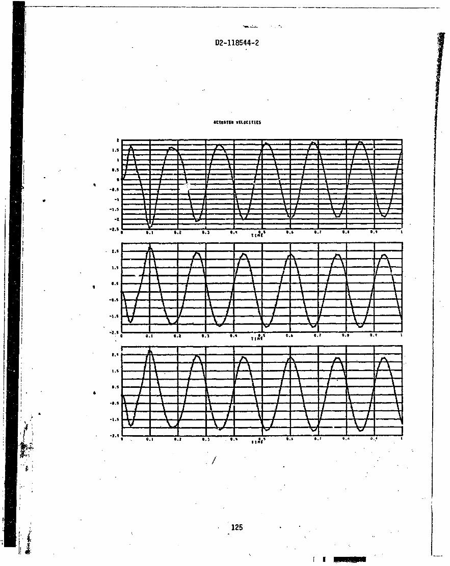
b. Actuator ve loc i t i e s : ,
c. Actuator posi t ion e r r o r d. Net forces on the actuator pistons

3.2 (Continued)
Group 4 - Complete pestvatjve. and Variable Arrays (may - not be plotted)
The variables and the i r derivatives (indexed by row) are listed below.
Deri vati ~ f 2 -- .. *T .. YT .. 0
Ox
"'Y 9
.. Yel
.. '%-
. .. ".1
.. 2 e6
X~
i 1 . z1 . 8 . 0 9
9
i e6
Index Variable --- 9
x~
9~ . z~
"'x
W Y " -9
e6
i el '
1- . z e6
X~
1
8
'4
4 Y el
Y @6
Vari ab1 e !&f i n i ti on ,
Table c.g, velocities
Table. rotational rates
Lateral bending velocities of actuator along ys axis
i
Lateral bending velocities along z axis
S j .
Inertial displacements~ o f table c.g.
Table ~uier angles . .
Bending deflections of actuators a t top of cylinder

Variable - z el
2 e6
P l1 . . . -
P '6
Pfl
P 26
0
"06
Qol
I '06 .
Variable Definition
Bending deflections of actuators a t top of cylinder
"Push" hydraulic pressure on actuator pistons .
"Pu? 1 " hydraulic pressure on actuator pistons
DerS vatives of no-1 oad valve f 1 ow
No-load valve flaw
Fi 1 tered actuator feedback ve1 oci t ies from second order f i3 t e r
F i I t e i d &ydback- displacements from second order f i l , ter

3.2 / (Continued)
Index Deer! vati ve -. Variable Variable Defini ti on
Voltage output of f i r s t order lag f i 1 t e r in pressure feedback
'a - .
I Vo1 tage output of ~ h i g n $ass f i l t e r i n pressure feedback
I Voltage output of forward loop conpensation f i 1 t e r s
3.3 ERROR MESSAGES
"THE IIITEGRATION HAS FAILED AT T = XX-XXXX. ABORT AND GO TO NEXT CASE." - occurs if fo r some reason the integration procedure cannot
continue. The program will abort the case and attempt t o process another one.
"ACTUATOR XXX HAS STROKED OUT.. .ABORT AND GO TO NEXT CASE." - occurs when an a c t u a t x has exceeded the maximum stroke. The program will abort the case and attempt to process another.
"ERROR hHILE INVE-RT~NG MASS MATRIX. . .GO TO .NEXT CASE. " - is se1 f-
explanatory. The user should look f o r errors i n input which may cause a singular or i 1 1-condi tionedpmass matrix.
There are also ,several error messages output by the i ntegration routine. When one of these messages occurs, it is likely tha t an instabi l i ty ha: occurred i n the hydraulics or electronics caused by improper data.

4.0 OPERATING INFORMATION
4.1 PROGRAN AND DATA SETUP
The program may be i npu t v i a s tandard EXEC I1 control cards on source o r r e loca t ab l e decks. A l l da ta f o r t h e program a r e i npu t on cards .
4.2 RUN INFORMATION - - -
-.1
Compilation time f o r t h e program is about 40 seconds. Representat ive . . runs of about one second of s imulat ion time have averaged approximately 8 minutes. Run time depends g r e a t l y upon the frequency o f t h e hydraul ics and e l e c t r o n i c s inputs . ~ -
5.0 PROGRAMING INFORMATION ~ . -
5.1 FLOW CHARTS
Program flow c h a r t s a r e shown on the fol lowing pages.

ACAVAP : Actual Actuator Positions , Velocities, and Accelerations
START
r - - ACTUATOR
I I
ACTUATOR VELOCITIES
! CALCULATE I . ACTUATOR I POSITIONS
I I I L - - - {- ACTUATOR
RETURN
DENTCY
CALCULATE ACTUATOR
RETURN b

. -
and Accel e r a t i on Commands ACDVC: Actuator Displacement, V e l o c i t y ,
CALCULATE , INERTIAL COMMANDS
piitzw-1 , fHG. BODY
ACCELERATIONS
BEG I N ---I ArTUUOR -- . I
CALCULATE ;OMM. INERTIAL
VELS. AND ACCELS .
t CALCULATE
ACT. LENGTH INERTIAL
COMPONENTS
OMM . ACTUATOR ENGTHS , VELS.
AND ACCEL
1-1 ACTUATOR
RETURN 'b

ACIBD:
. .
D2-118544-2
Actuator I n e r t i a and Bending Dynamics Parameters
START I---- ACTUATOR I I
CALCULATE EFFECTIVE
LATERAL ACT.
CALCULATE EFFECTIVE (BENDING
MASS
CALCULATE BENDING
FREQUENCY '

-- -
DATARD : Data Input Routine
PRINT TITLE
EAD & PRINT INERTIA & EOMETRY
ACTUATOR TRUCTURAL
EAD & PRINT FORCING
EAD & PRINT
Y DRAULICS
EAD & PRINT LECTRON IC
, .
-.
1 DATA f

D2-118544-2
FCN: ~ e r i v a t i v e Eva1 u a t i o n Contro l Rout ine
FIRST
ACTUATOR COMMANDS ( ACDVC)
COLUMN OF GEN. FORCES
FQNS. OF.
DERIVATIVES

FCN (continued)
TRANSFORM TABLE
VELOCITIES
HYDRAULIC AND ELEC.
RETURN
SET . JNDICATOR

GONADS : Mai n Control Routine
GONADS
READ
DATA
START f-- FREQUENCY I I
I FREQUENCY LOOP

HYSREL: Hydraul i c and S e r v o E l e c t r o n i e D e r i v a t i v e s
START HYSREL
I
?ayE: DYNAMICS
' , .
NO-LOAD VALVE FLO'EJ
I-- CAILCUL ATE
, AO-LOAD VALVE ,FLOW DEklVATIVES ACTUATOR
LOOP
CALCULATE PRESSURE
DERIVATIVES
NO YES
l4 * 1-1 Fl LTERED ACTUATOR FEEDBACK
FEEDBACKS DERIVATIVES I
SET VOLTAGE OUTPUT '
'

HYSREt (conti nued)
CALCULATE HIGH-PASS
DERIVATIVE
CALCULATE
FILTER
6 COMP . NO

INITIL: I n i t i a l i z a t ' r . . ~ HoutP'ne
START (7) INITIALIZE INTEGRATION CONf ROLS
INITIALIZE INERTIAL POSITION OF TABLE
ACTUATOR
ACTUATOR POSITION AND VEL.

,,-.- D2-118544-2
OUTPUT: Print and k i t e Output on Drun~ for r
I L--
OPTION

D2-118544-2
OUTPUT (continued)
OUTPUT
1 BEGIN LOQP 1 ON NUMBER -----j I I OPTIONS OF PLOT I

PLOTLR: P l o t Control Routine
START (-1 -
CALCULATE OPTIONS
I START 1
FROM DRGM
I I I
I e- ---------- DATA SET
LOOP
RETURN

i ' .
PLT3: Routine ' t o Form Three P lots per Frame
START - (-1
MAX IMUM
MINIMUM

5.2 SYSTEM-STRUCTURE
No over1 ay structure , is required for th i s program. , ,
5.3 LIBRARY SUBROUTINES
Several routines from the Johnson Space Center plotting l ibrary are used. These routines and thei r ' f~ ictions are :
FILMAV - advances the film GRDSET - se t s 1 i ne i ntensi t i e s GRID - forms a grid PLOTIV - plots an array of points PRINT - prints axis t i t l e s .
These routines may not be available a t another location; i n which case, the bes.t action would 1 i kely be t o substitute routines w i t h . the sa.me f4nctions rather than obtaining these routines from the JSC library.
5.4 PROGRAM LXTING
A cmpl ete program 1 i s t i ng -is shown on the fo l l mri ng pages.

......
I i R
EPR
OD
UC
HIL
ITy OF
fib
- -
#\
, ,
j<,.><
- .,
'; I
.
1 DUGIUL P
AG
E Iq POOR
I '
I'


. C
e: 8 1 - - c - C 0 u C 0 0
a N m u
- m C. L -". O ' C
"I' I
. - ! < . N . - . L I N . * I . . .- I r) . - . > . *
) . u .C ,
8 ,
I - Ir l
- .- I-,


- --4
. ---
- --
- -- .
-*
3J
LX
**
R'
l?
dY
,-
-J
l.
l4
O
J~
~D
~N
O~
OJ
~U
~~
~I
OY
/Q
N@
A~
YI YO
UY
O)
a
--.A
- 1_-
t t
lv
/ v
Al
~v
~-
~~
bp
o2
* .- -.----a-
~d
~*
m1
a'u
le~
il3li>
vt
*~
y~
a:
La
z
rauAsavi nonno) 6
. d
t'
7~
'0
~~
'3
Vl
'3
')
#~1YJ-Uv<
- -
av,,,~ O
OO
QO
~_
. , ~0
00
2.
1~
~~
n0
00
~~
~~
~0
00
f'
~~
~0
00
~~
~.
~~
0
d-
go
op
~O
~q
OO
~
V~
~~
~_
L?
_O
O~
~J
.J
QO
~
- ih
SQ
QO
OO
cooo
YT
,060do Y to06
- ..- OW
-oooooo u sooo dw
to
oo
oo
L co
o0
iii rFoooo : $of:
27
t &
@O
v toao
7 IO
OO
OO
0
0
11
OO
GO
OO
u 0
00
0
Sd
rN:
CI
O~
;
00
00
w
d~
~~
~~
oo
Qc
0Q
0
1 1
13
?!OOQO
Y (000 3
10
00
QO
u 06
?0
7
V
SO
60
00
Y
hOO
O
bill
St
0
5V
l ZO
O0
00
$
00
0
tob
o-'


00
19
7
32
* I
P9.. 2
O-J
!.l.r*
._--
.-
- ._
-_.
I O
OtS
2
. 3
1*
20
r
H{
l)
FH
(t)d
?l.
J)*
TfJ
,I,l
) 4
.
I?
1 0
01
5S
34.
RII
) w
R
XA
-
J
--- ,
OO
iSb
3S*
00
50
Iw
l*4
I !
- oO!b
l--3b
! &
?U
EL
ZU
A I
---.
---
?
00
1b
2
37
0
at3
1
RV
ZA
(2a
fl
0
I I
' R
I 0
01
13
KO
->!? d
~h
?
-P
A---.-----.
--.
0a!4
'--3'
* 3
98
3
0 V
(JI . T(
I,I#
JI
: I:
, aq
! to
-
; C
-
qo
* C
AL
L
CR
OIS
IR~
V~
VII
-
QO
l7l
. ell*
DO
NO
J
w1
*3
i %
C'
o
o!?
?,
42.
oO
b1
4J
) ~
HI
JI
~~
P(
~I
*V
~I
J~
-
---
---.
---
00
11
1
#a*
.
SO
CO
NT
tNU
E
! %
O
OI
OO
A*
R
ETU
RN
0
02
0 I
s-
ci
io
-.....-
- -
- - -
----.
Ir
:
r:
r: I


- -
.-. ...----
".A. -- ----.--
j IO~
~O
)~L
IYU
- .st,,
. .....
..*
.............. O
ttOO
,.a
., c 9
8 5
SO
~I
XS
VU
O
- rh
Z
Lt~
0.0
- I.
- I - --
- . --
.- -..-.-.-- ..--
d3
'0
~~
4
14
01
'91
31
1~
~
OC
Z SZZO
O-
I -m
i 5t7 0' rq-.-s-m
iiir sm
iirom
~ - 022-
CP
ZO
O
o~
*t
-t
f
~~
I'
I~
P*
IP
~~
BW
)I
(
~0
6'~
),
3l
!~
u
rlt
ClZ
00
I tS
*51
9C
'OB
l /S
*S
11
~'0
61
~S
.S
~~
C~
~~
-L
IX
S-
~~
~~
S
O&
.
an
[ZO
O-
--- -.
.&I
st to
e
. . i
nn
; roo-
.- - .------
----.---.- e
Lt
TS
IOO
I
ss
~o
r
-
VV
*~
W'
~V
tC
Ob
'T1
31
1~
1
.st
LC
10
0
~~
*s
~I
v~
JI
~s
I~
~I
~~
~I
x~
W
Vi
iY
B
1W
UO
.
.... ...
-. --- - .--- -------
.-- - .
. , .
----. -- ---
VV
3'A
V3
"11
1
I ZO
C'+
)?~
#I .C
1 O
Z! 00-


L;
- 8
tt4C
15
0 lv
bf nnr rt N
O m
oo
svr N
o:lV
?rrw
o2
SLML
I~O10010Zl3 ?
3A
31
e2
3~
31
- 1
52
VA
31
11
33
x3
A
Nv
YP
YO
~ *Ott
~V
AIN
A
SS
O_
Y>
~S
SO
~
O*Y
OA
e-
- :
.J
-,O l
iS
Ci
L.
,A
L_
Hf
iP
At
.
. . -
- .--
--- - -- - -
-


1
! ' i t '


EIO
~IU
IL
* 2
8 B
RE
TU
RN
1


. .
00
23
'l
57.
GO
T0
1
00
I
"'
'
oo
t3
Cs
a*
b
Rm
rm9-
o+b
,-- " .- -.
.
.- d
00
23
7
59
* .
CA
LL
RO
T
I
GO
TO
" s-.
- -
-Q
b2
74
00
*
id
7 .'
O0
2*1
'
I -I
61
-9
2 *
RJ
TC
tl3
,?G
s#
--
-.
-
- --
c Z-L
T~~
2-
,
. ..
. -Av-
' --
00
24
3
&2
* t
00
24
4
bS
* GO
TO
1
00
--
----
O
Q29
-4*
C3
-'ia
RfT
Wi?
rory
- '
----
-- .
. . -
--
--
-.-
., C
ALL
R
OT
O
OZY
7
6S
* , ,
-50
66
. ..--
- G
O
TO
10
0
> -
00
25
1
67.
. 9q
WRIYEtl7t9051_
:I
--
.---
--
---.
--.
- -
- . - -
-- - --
--.
-- -.
----
.
..
. .
-.---
- ..--
-.
----
-- -
- -
- J
. . . . . . - . . .
- . . . .
. . ,


. ,
I -,-..--
cu
b
! I .". -
--- --.
, .


5.5 SAMPLE PROBLEM '
1'-
The input data and output, both printout and plots, for a sample case -
are presented on the following pages. In the example, the table i s commanded to move sinusoidally i n the y direction with an amplitude of 0.1 inch. A1 though 18 frequency cases are specified, output from the f i r s t frequency case on1,y i s presented. In this example th,e valtje dynamics , forward 1 oop compensation f i 1 t e r , and posi ti on and rate feed- back second-order f i l t e r are ignored, Rate command and rate feedback gains are se t to zero.


. . *% ! ; 8 I
o N n.r ---so ON-om ma=.- - . o..--a o m - n r 0 . 0 0 . b

0 LC)'., I* t-h EL O N -
- 00 r :-.a- .I I - - *
0 r 00 : # I
0 .=-* N ..I*- r .a'* * L :.m19 * . ---- - 1 .*-a * I* = -*
a 8 ,
16 -N 0 ! 0 0 s 8 1 u IIr.1 L N Y O 0 .P.y* 7 - 0 - .. : - 3 ~ e c ' a - n . --• 8 ! - 9


rn.80)
0.002
0.001
-0
1 -0.901
-0.002
-0.891
-0.09q
-*. OO?


.;a- . s,;


'I- . - 02-118524-2


atrrrtw starts


15 0
LOO
5 0
-100
-250
-lnl


![ASC INVESTIGATIONS AND ENFORCEMENT: ISSUES AND …incrimination privilege; cfMaster Builders Assoc ofNSWv Plumbers & Gas Fitters Union [1987] ATPR 48,570 at 48,574-7. See R Ramsay](https://static.fdocuments.in/doc/165x107/602b78664bf5d97eca54434b/asc-investigations-and-enforcement-issues-and-incrimination-privilege-cfmaster.jpg)


