77-500 Intellisensor NEW v1 - STANLEY tools · 77-500 Intellisensor NEW v1 11/10/06 14:14 Pag. ......
16
1-77-500 I P EN E IntelliLaser ™ Pro Stud Finder and Laser Line Level with Continuous AC Warning INSTRUCTION MANUAL BEDIENUNGSANLEITUNG BRUGERVEJLEDNING KÄYTTÖOHJE INSTRUKTIONSHANDBOK INSTRUKSJONSBOK РУКОВОДСТВО ПО ЭКСПЛУАТАЦИИ 77-500 Intellisensor NEW v1 11/10/06 14:14 Pag
Transcript of 77-500 Intellisensor NEW v1 - STANLEY tools · 77-500 Intellisensor NEW v1 11/10/06 14:14 Pag. ......

1-77-500
I
P
EN
E
IntelliLaser™ ProStud Finder and Laser Line Level withContinuous AC Warning
INSTRUCTION MANUAL
BEDIENUNGSANLEITUNG
BRUGERVEJLEDNING
KÄYTTÖOHJE
INSTRUKTIONSHANDBOK
INSTRUKSJONSBOK
РУКОВОДСТВО ПО ЭКСПЛУАТАЦИИ
77-500 Intellisensor NEW v1 11/10/06 14:14 Pag
Studio Designer
Rectangle
2 • IntelliLaser Pro
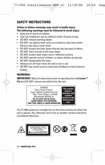
SAFETY INSTRUCTIONSFailure to follow warnings may result in bodily injury.The following warnings must be followed to avoid injury:• Keep out of reach of children.• Tool not suitable for use by children under 16 years of age.• DO NOT remove warning labels• DO NOT use optical tools such as a transit to view laser beam.
Serious eye injury could result• DO NOT project the laser beam directly into the eyes of others.• DO NOT stare directly at the laser beam.• DO NOT project laser beam onto a reflective surface.• DO NOT operate around children, or allow children to operate.• DO NOT disassemble the laser.• Always turn off laser when the tool is not in use.• DO NOT over reach so as to cause loss of balance or loss of secure
footing.
WARNINGS:IMPORTANT: Read all instructions prior to operating the IntelliLaser™Pro and DO NOT remove any labels from the tool.
The 77-500 produces a straight line on the same surface on which thetool is placed. Any reflection oft he line on another surface should beconsidered reference.
DANGERClass 2 Laser Product
Laser radiation emitted from toolMax. Power Output < 0.16mW
Wavelength: 630-670 nmDo not stare into the beam
AVOID DIRECT EYE EXPOSURETHIS TOOL EMITS A LASER RADIATION
This cautionnotice is
reminded witha sticker
located on thefront of each
unit.
77-500 Intellisensor NEW v1 11/10/06 14:14 Page 2

IntelliLaser Pro • 3
MAIN STUD SENSING/LASER UNIT
The Stanley® IntelliLaser™ Pro uses electronic signals tolocate the position of studs, joists or live AC wires throughdrywall and other common wall materials. Once the edge ofthe stud has been detected, the IntelliLaser™ Pro LCD display givesvisual and audio indications that allow you to easily pinpoint the stud’sedge position. A pencil line allows you to quickly note the location ofthe stud edges.
The Stanley® IntelliLaser™ Pro stud sensor generates a vertical laserplane. The unit can also be tilted to produce a laser plane at anyangle.
The IntelliLaser™ Pro allows the user to locate wood and metal studsthrough common wall materials up to 38mm (11/2") thick.
The IntelliLaser™ Pro provides automatic calibration, a backlit LCDscreen, auto shut off and heavy duty ABS construction.
Depth detection selected by side button for 12mm (1/2"), 25mm (1") and38mm (11/2").
LASER PODThe addition of the laser pod opens up the functionality of the studfinder. The unit is mountable using adhesive pads (included).Retractable feet keep the adhesive away from the surface duringplacement. The laser pod can be tilted ±10°once it is attached to thesurface without removing the adhesive. This allows for easyrepositioning of the laser plane. The laser pod can be set to level,plumb or any other angle required. With the laser pod mounted to thewall horizontally, you are free to use the main stud sensor laser podand mark both the height and stud locations at the same time.
The IntelliLaser™ Pro laser pod generates a horizontal or verticallaser plane. It can also be mounted to the wall to reproduce any anglerequired.
The IntelliLaser™ Pro laser pod provides heavy duty ABS constructionwith large rubber pads to provide a firm grip and superior impactresistance.
77-500 Intellisensor NEW v1 11/10/06 14:14 Pag

4 • IntelliLaser Pro
LASER CLASSIFICATION
This product produces a visible laser beam. It is a Class 2 laserproduct in accordance with EN60825-1/A1:2002.
This product complies with all applicable portions of title 21 of theUSA Code of Federal Regulations set by the Dept of Health, Educationand Welfare, the Food & Drug Administration, the Center for Devices& the Bureau of Radiological Health.
DECLARATION OF CONFORMITYThe Stanley Works declares that these products conform to:EN60825-1, 89/336/EEC; EN61010, 2001/95/EC, 2002/96/EC, EN61000-6(EN50082-1), EN61000-6-3(EN50081-1)
Signed by
Alisdair CummingDirector of Engineering & TechnologyHellaby Industrial EstateRotherham02/06
77-500 Intellisensor NEW v1 11/10/06 14:14 Pag

IntelliLaser Pro • 5
ILLUSTRATION 1
ILLUSTRATION 2
ILLUSTRATION 3
Indicator Mark
Level & PlumbVials
Live Wire LEDBacklit LCD
Depth DetectionMode Indicator
Lit When LiveWire is Detected
Unit isCalibrating
Laser Plane ON
IndicatorGraphic
Low BatteryIndicator
Live Wire
A = Wood or metal stud detection up to 12mm (1/2")B = Wood or metal stud detection up to 25mm (1")C = Wood or metal stud detection up to 38mm (1-11/2")
CalibratingComplete
Ready to Scan
ON Button / DepthDetection Mode
Selection
77-500 Intellisensor NEW v1 11/10/06 14:14 Pag
6 • IntelliLaser Pro
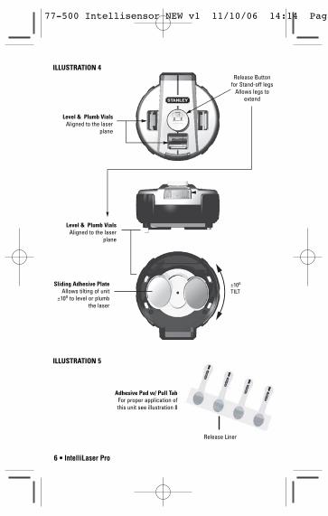
ILLUSTRATION 4
Level & Plumb VialsAligned to the laser
plane
Level & Plumb VialsAligned to the laser
plane
Sliding Adhesive PlateAllows tilting of unit
±10o to level or plumbthe laser
Release Buttonfor Stand-off legs
Allows legs toextend
±10o
TILT
ILLUSTRATION 5
Adhesive Pad w/ Pull TabFor proper application ofthis unit see illustration 8
Release Liner
77-500 Intellisensor NEW v1 11/10/06 14:14 Pag
IntelliLaser Pro • 7
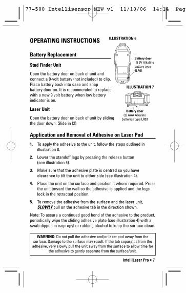
OPERATING INSTRUCTIONS
Battery Replacement
Stud Finder Unit
Open the battery door on back of unit andconnect a 9-volt battery (not included) to clip.Place battery back into case and snapbattery door on. It is recommended to replacewith a new 9 volt battery when low batteryindicator is on.
Laser Unit
Open the battery door on back of unit by slidingthe door down. Slide in (2)
Application and Removal of Adhesive on Laser Pod
1. To apply the adhesive to the unit, follow the steps outlined in illustration 8.
2. Lower the standoff legs by pressing the release button (see illustration 4).
3. Make sure that the adhesive plate is centred so you haveclearance to tilt the unit to either side (see illustration 4).
4. Place the unit on the surface and position it where required. Pressthe unit toward the wall so the adhesive is applied and the legslock in the retracted position.
5. To remove the adhesive from the surface and the laser unit,SLOWLY pull on the adhesive tab in the direction shown.
Note: To assure a continued good bond of the adhesive to the product,periodically wipe the sliding adhesive plate (see illustration 4) with aswab dipped in isopropyl or rubbing alcohol to keep the surface clean.
ILLUSTRATION 6
ILLUSTRATION 7
Battery door(1) 9V Alkalinebattery type6LR61
Battery door(2) AAA Alkaline
batteries type LR03
WARNING: Do not pull the adhesive and/or laser pod away from thesurface. Damage to the surface may result. If the tab separates from the
adhesive, very slowly pull the unit away from the surface to allow time forthe adhesive to gently separate from the surface/unit.
77-500 Intellisensor NEW v1 11/10/06 14:14 Pag
8 • IntelliLaser Pro
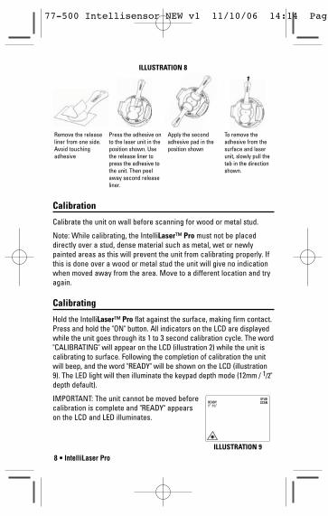
ILLUSTRATION 8
Remove the releaseliner from one side.Avoid touchingadhesive
Press the adhesive onto the laser unit in theposition shown. Usethe release liner topress the adhesive tothe unit. Then peelaway second releaseliner.
Apply the secondadhesive pad in theposition shown
To remove theadhesive from thesurface and laserunit, slowly pull thetab in the directionshown.
Calibration
Calibrate the unit on wall before scanning for wood or metal stud.
Note: While calibrating, the IntelliLaser™ Pro must not be placeddirectly over a stud, dense material such as metal, wet or newlypainted areas as this will prevent the unit from calibrating properly. Ifthis is done over a wood or metal stud the unit will give no indicationwhen moved away from the area. Move to a different location and tryagain.
Calibrating
Hold the IntelliLaser™ Pro flat against the surface, making firm contact.Press and hold the "ON" button. All indicators on the LCD are displayedwhile the unit goes through its 1 to 3 second calibration cycle. The word"CALIBRATING" will appear on the LCD (illustration 2) while the unit iscalibrating to surface. Following the completion of calibration the unitwill beep, and the word "READY" will be shown on the LCD (illustration9). The LED light will then illuminate the keypad depth mode (12mm / 1/2"depth default).
IMPORTANT: The unit cannot be moved beforecalibration is complete and "READY" appearson the LCD and LED illuminates.
ILLUSTRATION 9
77-500 Intellisensor NEW v1 11/10/06 14:14 Pag

IntelliLaser Pro • 9
Notes:
1. Laser line is always on when holding the “ON” button.2. Continue to hold the “ON” button during stud detection.
USAGE
Selecting Depth Detection
1. Depress and hold "ON" button once (1x) to select 12mm (1/2") readdepth detection. The 12mm (1/2") mode LED will illuminate(illustration 3). The unit will then calibrate, followed by a beep anda "READY" displayed on the LCD.
2. "Double-click" / Depress and hold ON button twice (2x) to select25mm (1") read depth detection. The 25mm (1") mode LED willilluminate (illustration 3). The unit will then calibrate, followed by abeep and a "READY" displayed on the LCD.
3. "Triple-click"/ Depress "ON" button three times (3x) to select 38mm(1-11/2") read depth detection. The 38mm (1-11/2") mode LED willilluminate (illustration 3). The unit will then calibrate, followed by abeep and a "READY" displayed on the LCD.
IMPORTANT: The unit cannot be moved before calibration is completeand "READY"
Detecting Wood or Metal Studs
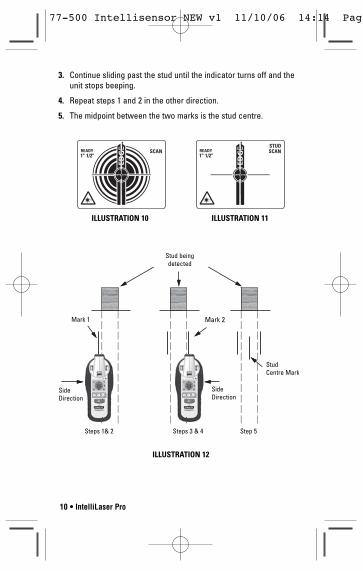
1. Once the unit is calibrated, slide the unit across the surface in astraight line horizontally. As the unit gets closer to the stud, thecross will appear and the indicator rings will illuminate insuccession from the largest to the smallest as shown in illustration10. When the stud edge is detected, the “stud” indicator andvertical “EDGE” symbol will appear as shown in illustration 11. The unit will also sound a constant tone.
2. Use the indicator line to mark the stud edge.
77-500 Intellisensor NEW v1 11/10/06 14:14 Pag
10 • IntelliLaser Pro
3. Continue sliding past the stud until the indicator turns off and theunit stops beeping.
4. Repeat steps 1 and 2 in the other direction.
5. The midpoint between the two marks is the stud centre.
ILLUSTRATION 10 ILLUSTRATION 11
ILLUSTRATION 12
Stud beingdetected
Mark 1 Mark 2
Steps 1& 2 Steps 3 & 4 Step 5
StudCentre Mark
SideDirection
SideDirection
77-500 Intellisensor NEW v1 11/10/06 14:14 Pag

IntelliLaser Pro • 11
Detecting Live Wires
The Live Wire Detection feature is always on and the“Live Wire” iconwill be displayed on the LCD. When a Live Wire is detected, the redlive wire LED indicator will be on.(see illustration 1 & 2).
Static electricity charges that can develop on drywall and othersurfaces will spread the voltage detection area many inches to eachside of the actual electrical wire. To aid in locating the wire position,scan holding the unit 1/2 inch away from the wall surface or placeother hand on surface approximately 12 inches from sensor.
Warning: shielded wires or live wires in metal conduits, casings,metalized walls or thick, dense walls, will not be detected. Alwaysturn AC power off when working near wiring.
The IntelliLaser™ Pro is designed to detect 230 volts AC in liveelectrical wires. It will also detect the presence of live wires havinggreater than 230 volts.
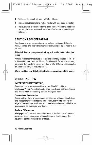
Laser Plane
1. Laser plane in the stud detection mode is always on, a laser planeicon is also shown on the LCD. It can be turned off by pressing
“ ” button once.
2. Laser plane can also be turned on individually by pressing “ ”button once or pressing again to turn it off.
ILLUSTRATION 13 Laser Aperture
Vials
77-500 Intellisensor NEW v1 11/10/06 14:14 Pag
12 • IntelliLaser Pro
3. The Laser plane will be auto - off after 1 hour.
4. The projected laser plane will coincide with stud edge indicator.
5. The level vials are aligned to the laser plane. When the bubble iscentred, the laser plane will be vertical/horizontal (depending onvial used).
CAUTIONS ON OPERATINGYou should always use caution when nailing, cutting or drilling inwalls, ceilings and floors that may contain wiring or pipes near to thesurface.
Shielded, dead or non-powered wiring will not be detected as livewires.
Always remember that studs or joists are normally spaced 41cm (16")or 61cm (24") apart and are 38mm (11/2") in width. To avoid surprises,be aware that anything closer together or of a different width may bean additional stud, or joist fire break.
When working near AC electrical wires, always turn off the power.
OPERATING TIPSIMPORTANT SAFETY NOTICETo ensure proper detection of live wires, ALWAYS hold theIntelliLaser™ Pro Pro in the handle area only. Grasp between fingersand thumb while maintaining contact with your palm.
Conventional Construction Doors and windows are commonly constructed with additional studsand headers for added stability. The IntelliLaser™ Pro detects theedge of these double studs and solid headers and emits and holds anaudio signal as it crosses over them.
Surface DifferencesWallpaper — There will be no difference in the function of the studsensor on surfaces covered with wallpaper or fabric unless thecoverings contain metallic foil or fibres.
77-500 Intellisensor NEW v1 11/10/06 14:14 Pag

IntelliLaser Pro • 13
Plaster and Lath — Unless the plaster and lath is exceptionally thickor has metal mesh in it there will be no problem with the unitfunctioning properly.
Ceiling or Textured Surfaces — When dealing with a rough surfacesuch as a sprayed ceiling, use a piece of cardboard when scanningthe surface. Run through the calibration technique described earlierWITH the piece of cardboard between the stud sensor and thesurface. Also, it is particularly important in this application toremember to keep your free hand away from the unit.
SPECIFICATIONS
Utilising the procedure of scanning and marking from two sides,IntelliLaser™ Pro will find the stud center with 1/8” accuracy for woodand 1/4” accuracy for metal. When measuring a wood or metal stud, it is recommended the IntelliSensor™ to be used at 20-35% relativehumidity.
Battery : Main unit: 1 x 9V Alkaline type 6LR61
Laser pod: 2 x AAA Alkaline type LR03
Shock Resistance: up to 91cm (3’)
Operating Temperature: -7°C to +49°C (+20°F to +120°F)
Storage Temperature: -29°C to +66°C (-20°F to +150°F)
Laser Class: 2 < 0.16 mW power output
Laser diode: 635nm Class 2
Laser accuracy: 12mm (1/2”) at 6m (20’)
Length of projected Laser Line: up to 6m (20’)
This is a Class 2 laser tool and is manufactured to comply withinternational safety rule IEC EN60825-1.
77-500 Intellisensor NEW v1 11/10/06 14:14 Pag

14 • IntelliLaser Pro
MAINTENANCE & CAREThe IntelliLaser™ Pro is not waterproof. Do not allow the unit to getwet. Damage to internal circuits will result.
Do not leave the IntelliLaser™ Pro out in direct sunlight or expose it tohigh temperatures. The housing and some internal parts are made ofplastic and may become deformed at high temperatures.
Do not store the IntelliLaser™ Pro in a cold environment. Moisture willform on interior parts when warming up. The moisture could fog uplaser windows and cause corrosion of internal circuit boards.
When working in dusty locations, some dirt will collect on the laserwindow. Remove any moisture or dirt with a soft, dry cloth. Do not useaggressive cleaning agents or solvents.
Remove batteries before storage of the instrument.
ENVIRONMENTAL PROTECTIONSort the product, packaging and accessories for environmentallyfriendly recycling when disposing of them.
Dispose of used batteries in an environmentally friendly way inaccordance with local regulations. Do not throw batteries in the fire or in the household waste
77-500 Intellisensor NEW v1 11/10/06 14:14 Pag
IntelliLaser Pro • 15
WARRANTY
One Year Warranty
Stanley Tools warrants its electronic measuring tools againstdeficiencies in materials or workmanship for one year from date ofpurchase.
Deficient products will be repaired or replaced, at Stanley Tools’option, if sent together with proof of purchase to:-
Stanley UK Sales Limited,Gowerton Road,Brackmills,NorthamptonNN4 7BW
This Warranty does not cover deficiencies caused by accidentaldamage, wear and tear, use other than in accordance with themanufacturer's instructions or repair or alteration of this product notauthorised by Stanley Tools. Repair or replacement under thisWarranty does not affect the expiry date of the Warranty. To theextent permitted by law, Stanley Tools shall not be liable under thisWarranty for indirect or consequential loss resulting from deficienciesin this product.
This Warranty may not be varied without the authorisation of StanleyTools.
This Warranty does not affect the statutory rights of consumerpurchasers of this product.
This Warranty shall be governed by and construed in accordance withthe laws of England and Stanley Tools and the purchaser eachirrevocably agrees to submit to the exclusive jurisdiction of the courtsof England over any claim or matter arising under or in connectionwith this Warranty.
77-500 Intellisensor NEW v1 11/10/06 14:14 Pag

©2006 THE STANLEY WORKS:www.stanleyworks.com
BUK-1-77-500 (01/07) Issue 1
Stanley Europe, Egide Walschaertsstraat 14-16,2800 Mechelen, Belgium
77-500 Intellisensor NEW v1 11/10/06 14:15 Page 100