7%!,4(/&+%.45#+9 .BUUIFX( #FWJO TRANSPORTATION CAB ... · prevent caving or deterioration of...
28
Governor An Equal Opportunity Employer M/F/D TRANSPORTATION CAB December 5, 2017 CALL NO. 106 CONTRACT ID NO. 171050 ADDENDUM # 2 Subject: Clay County, STP 6000 (112) Letting December 8, 2017 (1)Added – Special Notes – Pages 1-10 of 10 (2)Revised –Bid Items - Pages 217-222(a) of 222 (3)Revised –Plan Sheets – R2L, DWG 27581 (S1, S8, S9, S11) Proposal revisions are available at http://transportation.ky.gov/Construction- Procurement/. Plan revisions are available at https://www.kytcplanroom.com/View/Default.aspx If you have any questions, please contact us at 502-564-3500. Sincerely, Rachel Mills, P.E. Director Division of Construction Procurement RM:mw Enclosures
Transcript of 7%!,4(/&+%.45#+9 .BUUIFX( #FWJO TRANSPORTATION CAB ... · prevent caving or deterioration of...

Governor
An Equal Opportunity Employer M/F/D
TRANSPORTATION CAB
December 5, 2017
CALL NO. 106
CONTRACT ID NO. 171050
ADDENDUM # 2
Subject: Clay County, STP 6000 (112)
Letting December 8, 2017
(1)Added – Special Notes – Pages 1-10 of 10
(2)Revised –Bid Items - Pages 217-222(a) of 222
(3)Revised –Plan Sheets – R2L, DWG 27581 (S1, S8, S9, S11)
Proposal revisions are available at http://transportation.ky.gov/Construction-
Procurement/.
Plan revisions are available at https://www.kytcplanroom.com/View/Default.aspx
If you have any questions, please contact us at 502-564-3500.
Sincerely,
Rachel Mills, P.E.
Director
Division of Construction Procurement
RM:mw
Enclosures

11C
1
SPECIAL NOTE FOR DRILLED SHAFTS
1.0 DESCRIPTION. Furnish all equipment, materials and labor necessary for constructing reinforced concrete drilled shafts in cylindrically excavated holes according to the details shown on the plans or as the Engineer directs. Construct the shaft to the lines and dimensions shown on the plans, or as the Engineer directs. Section references herein are to the Department’s 2012 Standard Specifications for Road and Bridge Construction. 2.0 MATERIALS.
2.1 Concrete. Use Class A Modified concrete unless otherwise shown on the plans. The slump at the time of placement shall be 6.5 to 9.5 inches, the coarse aggregate shall be size 67, 68, 78, 8 or 9M, and the water/cementitious material ratio shall not exceed 0.45. Include water reducing and retarding admixtures. Type F high range water reducers used in combination with retarding admixtures or Type G high range water reducers fully meeting trial batch requirements are permitted and Class F fly ash is permitted in conformance with Section 601. Design the mix such that the concrete slump exceeds 4 inches at 4 hours after batching. If the estimated concrete transport, plus time to complete placement, exceeds 4 hours, design the concrete to have a slump that exceeds 4 inches or more for the greater time after batching and demonstrate that the slump requirement can be achieved after the extended time period using a trial batch.
Perform trial batches prior to beginning drilled shaft construction in order to demonstrate the adequacy of the proposed concrete mix. Demonstrate that the mix to be used will meet the requirements for temperature, slump, air content, water/cementitious material ratio, and compressive strength. Use the ingredients, proportions and equipment (including batching, mixing, and delivery) to be used on the project. Make at least 2 independent consecutive trial batches of 3 cubic yards each using the same mix proportions and meeting all specification requirements for mix design approval. Submit a report containing these results for slump, air content, water/cement ratio, temperature, and compressive strength and mix proportions for each trial batch to the Engineer for review and approval. Failure to demonstrate the adequacy of the concrete mix, methods, or equipment to the Engineer is cause for the Engineer to require appropriate alterations in concrete mix, equipment, and/or method by the Contractor to eliminate unsatisfactory results. Perform additional trial batches required to demonstrate the adequacy of the concrete mix, method, or equipment.
2.2 Steel Reinforcement. Provide Grade 60 deformed bars conforming to Section 811 of the Standard Specifications. Rail steel is permitted for straight bars only. Place according to Section 602 of the Standard Specifications, this Special Note, and the plans. Use non-corrosive centering devices and feet to maintain the specified reinforcement clearances.
2.3 Casings. Provide casing meeting the requirements of ASTM A 252 Grade 2 or better unless otherwise specified. Ensure casing is smooth, clean, watertight, true and straight, and of ample strength to withstand handling, installation, and extraction stresses and the pressure of both concrete and the surrounding earth materials. Ensure the outside diameter of casing is not less than the specified diameter of shaft.
Use only continuous casings. Cut off the casing at the prescribed elevation and trim to within tolerances prior to acceptance. Extend casing into bedrock a sufficient distance to stabilize the shaft excavation against collapse, excessive deformation, and/or flow of water if required and/or shown on the plans.
Install from the work platform continuous casing meeting the design thickness requirements, but not less than 3/8 inch, to the elevations shown on the plans. When drilled
CLAY COUNTY STP 6000 (112)
ADDED ADDENDUM #2: 12-5-17 Contract ID: 171050
Page 1 of 10

11C
2
shafts are located in open water areas, extend casings above the water elevation to the plan tip elevation to protect the shaft concrete from water action during concrete placement and curing. All casing is permanent unless temporary casing is specified in the contract drawings or documents. Permanent casing is incidental to the applicable drilled shaft unit bid price unless noted otherwise in the contract. Temporary casing may be required for drilled shafts not socketed into bedrock. If temporary surface casings are used, extend each casing up to the work platform. Remove all temporary surface casing prior to final acceptance unless otherwise permitted by the Central Office Construction Engineer.
Ensure casing splices have full penetration butt welds conforming to the current edition of AWS D1.1 with no exterior or interior splice plates and produce true and straight casing.
2.4 Slurry. When slurry is to be used for installation of the Drilled Shaft, submit a detailed plan for its use and disposal. The plan should include, but not be limited to the following:
1) Material properties 2) Mixing requirements and procedures 3) Testing requirements 4) Placement procedures 5) Disposal techniques
Obtain the Central Office Division of Construction’s approval for the slurry use and
disposal plan before installing drilled shafts. 2.5 Tremies. Provide tremies of sufficient length, weight, and diameter to discharge
concrete at the shaft base elevation. Ensure the tremie diameter is least 6 times the maximum size coarse aggregate to be used in the concrete mix and no less than 10 inches. Provide adequate wall thickness to prevent crimping or sharp bends that restrict concrete placement. Support tremies used for depositing concrete in a dry drilled shaft excavation so that the free fall of the concrete does not cause the shaft excavation to cave or slough. Maintain a clean and smooth tremie surface to permit both flow of concrete and unimpeded withdrawal during concrete placement. Do not allow any aluminum parts to contact the concrete. Construct tremies used to deposit concrete for wet excavations so that they are watertight and will readily discharge concrete.
2.6 Concrete Pumps. Provide pump lines with a minimum diameter of 5 inches and
watertight joints. 2.7 Drop Chutes. Do not use aluminum drop chutes.
3.0 CONSTRUCTION.
3.1 Preconstruction. 3.1.1 Prequalification. The Department will require prequalification by the
Division of Construction Procurement before accepting a bid for the construction of Drilled Shafts.
3.1.2 Pre-Bid Inspection. Inspect both the project site and all subsurface
information, including any soil or rock samples, prior to submitting a bid. Contact the Geotechnical Branch (502-564-2374) to schedule a viewing of the subsurface information. Failure to inspect the project site and view the
CLAY COUNTY STP 6000 (112)
ADDED ADDENDUM #2: 12-5-17 Contract ID: 171050
Page 2 of 10

11C
3
subsurface information will result in the forfeiture of the right to file a claim based on site conditions and may result in disqualification from the project.
3.1.3 Drilled Shaft Installation Plan. Upon request, the Department will review
a Drilled Shaft Installation Plan. Submit the plan no later than 45 calendar days prior to constructing drilled shafts. Items covered in this plan should include, but not be limited to the following:
1) Name and experience record of jobsite drilled shaft superintendent and
foremen in charge of drilled shaft operations for each shift. 2) List and size of proposed equipment including cranes, drills, augers,
bailing buckets, final cleaning equipment, de-sanding equipment, slurry pumps, core sampling equipment, tremies or concrete pumps, casings, etc.
3) Details of overall construction operation sequence and the sequence of shaft construction in the bents or groups.
4) Details of shaft excavation methods including methods to over-ream or roughen shaft walls, if necessary.
5) Details of slurry when the use of slurry is anticipated. Include methods to mix, circulate, and de-sand the proposed slurry. Provide details of proposed testing, test methods, sampling methods, and test equipment.
6) Details of proposed methods to clean shaft and inside of casing after initial excavation.
7) Details of reinforcement handling, lifting, and placement including support and method to center in shaft. Also include rebar cage support during concrete placement and temporary casing removal.
8) Details of concrete placement including procedures for concrete tremie or pump. Include initial placement, raising during placement, and overfilling of the shaft to expel contaminated concrete.
9) Required submittals including shop drawings and concrete design mixes.
10) Other information shown in the plans or requested by the Engineer. 11) Special considerations for wet construction. 12) Details of environmental control procedures to protect the environment
from discharge of excavation spoil, slurry (natural and mineral), and concrete over-pour.
The Division of Construction will review the submitted procedure and
provide comments and recommendations. The Contractor is responsible for satisfactory construction and ultimate performance of the Drilled Shaft.
3.2 General Construction. Construct drilled shafts as indicated in the plans or
described in this Special Note by either the dry or wet method. When the plans describe a particular method of construction, use this method unless the Engineer permits otherwise. When the plans do not describe a particular method, propose a method on the basis of its suitability to the site conditions. Approval of this proposed method is contingent upon the satisfactory results of the technique shaft.
The construction of the first drilled shaft or technique shaft will be used to determine if the methods and equipment used by the contractor are sufficient to produce a completed shaft meeting the requirements of the plans and specifications. Ability to control dimensions and alignment of excavations within tolerances; to seal the casing into impervious materials; to prevent caving or deterioration of subsurface materials by the use of slurry or other means; to
CLAY COUNTY STP 6000 (112)
ADDED ADDENDUM #2: 12-5-17 Contract ID: 171050
Page 3 of 10

11C
4
properly clean the completed shaft excavation; to construct excavations in open water areas when required by the plans; to establish methods for belling or over-reaming when required by the plans; to determine the elevation of ground water; to satisfactorily handle, lift, place, and support the reinforcement cage; to satisfactorily place concrete meeting the specifications within the prescribed time frame; and to satisfactorily execute any other necessary construction operations will be evaluated during construction of the first shaft(s). Revise the methods and equipment as necessary at any time during the construction of the first shaft when unable to satisfactorily carry out any of the necessary operations described above or unable to control the dimensions and alignment of the shaft excavation within tolerances. Accurately locate technique so they may be used in the finished structure unless directed otherwise in the contract document or by the Engineer.
If at any time the Contractor fails to satisfactorily demonstrate, to the satisfaction of the Engineer, the adequacy of methods or equipment and alterations are required, additional technique shafts will be required at no additional cost to the Department and with no extension of contract time. Additional technique shafts shall be located as near as possible to the proposed production shafts but in a location as not to interfere with other construction activities. Once approval has been given to construct production shafts, no changes will be permitted in the methods or equipment used to construct the satisfactory shaft without written approval of the Engineer.
Do not make a claim against the Department for costs of construction delays, or any materials, labor, or equipment that may be necessary due to the Contractor’s failure to furnish drilled shafts of a length sufficient to obtain the required bearing values, or for variations in length due to subsurface conditions that may be encountered. Soundings, boring logs, soil profiles, or other subsurface data included in the Contract documents are used by the Department for design and making preliminary estimates of quantities and should be used only at the risk of the Contractor for determining equipment, materials, or labor necessary for drilling shafts as required by the contract.
When necessary, set temporary removable surface casing. Use surface casing of sufficient length to prevent caving of the surface soils and to aid in maintaining shaft position and alignment. Pre-drilling with slurry and/or over-reaming to the outside diameter of the casing may be required to install the surface casing at some sites.
Provide equipment capable of constructing shafts to the deepest shaft depth shown in the plans plus 15 feet, 20 percent greater than the longest shaft (measured from the ground or water surface to the tip of the shaft), or 3 times the shaft diameter, whichever is greater. Blasting excavation methods are not permitted.
Use permanent casing unless otherwise noted in the Contract. Place casing as shown on the plans before beginning excavation. If full penetration cannot be attained, the Engineer may direct that excavation through the casing be accomplished and the casing advanced until reaching the plan tip elevation. In some cases, over-reaming to the outside diameter of the casing may be required before placing the casing. Cut off the casing at the prescribed elevation and leave the remainder of the casing in place. Do not use vibratory hammers for casing installation within 50 feet of shafts that have been completed less than 24 hours.
3.2.1 Dry Construction Method. Use the dry construction method only at sites where
the ground water table and soil conditions (generally stiff to hard clays or rock above the water table) make it feasible to construct the shaft in a relatively dry excavation and where the sides and bottom of the shaft are stable and may be visually inspected by the Engineer prior to placing the concrete. The dry construction method consists of drilling the shaft excavation, removing accumulated seepage water and loose material from the excavation, and placing the shaft concrete in a relatively dry excavation.
CLAY COUNTY STP 6000 (112)
ADDED ADDENDUM #2: 12-5-17 Contract ID: 171050
Page 4 of 10

11C
5
3.2.2 Wet Construction Method. Use the wet construction method at all sites where it is impractical to excavate by the dry method. The wet construction method consists of drilling the shaft excavation below the water table, keeping the shaft filled with water (including natural slurry formed during the drilling process) or slurry as defined in part 2.4 of this Special Note, desanding and cleaning the slurry as required, final cleaning of the excavation by means of a bailing bucket, air lift, submersible pump or other approved devices and placing the shaft concrete (with a tremie or concrete pump beginning at the shaft bottom) which displaces the water or slurry as concrete is placed.
Where drilled shafts are located in open water areas, construct the shafts by the wet method using casings extending from above water elevation to the plan casing tip elevation to protect the shaft concrete from water action during placement and curing. Install the casing in a manner that will produce a positive seal at the bottom of the casing.
3.3 Slurry. When the Contractor elects to use slurry, adjust construction operations so
that the slurry is in contact with the bottom 5 feet of the shaft for less than 4 hours unless the Engineer approves otherwise. If the 4-hour limit is exceeded, over-ream the bottom 5 feet of shaft.
3.4 Cleaning. Over-reaming, cleaning, or wire brushing the sidewalls of the shaft
excavation and permanent casings may be necessary to remove the depth of softening or to remove excessive slurry cake buildup as indicated by sidewall samples or other test methods employed by the Engineer. Over-ream around the perimeter of the excavation a minimum depth of 1/2 inch and maximum depth of 3 inches.
3.5 Subsurface Exploration. Take subsurface exploration borings when shown on the
plans or as the Engineer directs to determine the character of the material that the shaft extends through and the material directly below the shaft excavation. Complete subsurface exploration borings prior to beginning excavation for any drilled shaft in a group. Unless directed otherwise, extend subsurface exploration borings a minimum depth of 3 shaft diameters but not less than 10 feet below the bottom of the anticipated tip of drilled shaft excavation as shown on the plans. For subsurface exploration borings where soil sampling is required use thin-wall tube samples and perform standard penetration tests according to the Department’s current Geotechnical Manual. When shafts extend into bedrock, soil samples are not required unless otherwise specified. Perform rock core drilling according to the Department’s Geotechnical Manual. When the Engineer directs, perform additional subsurface exploration borings prior to drilled shaft construction. Measure soil samples and/or rock cores and visually identify and describe them on the subsurface log according to the Department’s current Geotechnical Manual. Subsurface exploration borings must be performed by contractors/consultants prequalified by the Department’s Division of Professional Services for Geotechnical Drilling Services at the time that field work begins.
The Engineer or geotechnical branch representative may be on-site during the subsurface exploration process to evaluate the soil and/or rock core samples. The Engineer or geotechnical branch representative will determine the need to extend the borings to depths greater than the depths previously specified. Handle, label, identify, and store soil and/or rock samples according to the Department's current Geotechnical Manual and deliver them with the subsurface logs to the geotechnical branch’s rock core lab in Frankfort within 24-hours of completing the borings, unless directed otherwise.
The Engineer will inspect the soil samples and/or cores and determine the final depth of required excavation (final drilled shaft tip elevation) based on evaluation of the material's suitability. The Engineer will establish the final tip elevations for shaft locations, other than
CLAY COUNTY STP 6000 (112)
ADDED ADDENDUM #2: 12-5-17 Contract ID: 171050
Page 5 of 10

11C
6
those for which subsurface exploration borings have been performed, based on the results of the subsurface exploration. Within 15 calendar days after completion of the subsurface exploration borings, the Engineer will notify the contractor of the final tip elevations for shaft locations.
3.6 Excavations. The plans indicate the expected depths, the top of shaft elevations, and the estimated bottom of shaft elevations between which the drilled shaft are to be constructed. Drilled shafts may be extended deeper when the Engineer determines that the material encountered while drilling the shaft excavation is unsuitable and/or is not the same as anticipated in the design of the drilled shaft. Drilled shafts may be shortened when the Engineer determines the material encountered is better than that anticipated.
Begin drilled shaft excavation the excavation, excavation inspection, reinforcement placement, and concrete placement can be completed as one continuous operation. Do not construct new shafts within 24 hours adjacent to recently completed shafts if the center-to-center spacing is less than 3 shaft diameters.
Dispose of excavated material removed from the shaft according to the Standard Specifications or the contract documents.
Do not allow workmen to enter the shaft excavation for any reason unless both a suitable casing has been installed and adequate safety equipment and procedures have been provided to the workmen entering the excavation. Recommended Procedures for the Entry of Drilled Shaft Foundation Excavations, prepared by ADSC: The International Association of Foundation Drilling provides guideline recommendations for down-hole entry of drilled excavations.
3.7 Obstructions. Remove subsurface obstructions at drilled shaft locations. Such obstructions may include man-made materials such as old concrete foundations or natural materials such as boulders. Blasting is not permitted.
3.8 Inspections of Excavations. Provide equipment for checking the dimensions and
alignment of each shaft excavation. Determine the dimensions and alignment of the shaft excavation under the observation and direction of the Engineer. Provide equipment necessary to verify shaft cleanliness for the method of inspection selected by the Engineer.
Measure final shaft depths with a weighted tape or other approved methods after final cleaning. Ensure the base of each shaft has less than ½ inch of sediment at the time of concrete placement. For dry excavations, do not allow the depth of water to exceed 3 inches for tremie or pump methods of concrete placement. Verify shaft cleanliness to the Engineer using direct visual inspection or other method the Engineers determines acceptable. Video camera or underwater inspection procedures may be used if specified in the plans. Inspect the side surfaces of rock sockets to ensure they are rough and of such condition to ensure bond between the shaft concrete and the rock. Calipers, bent rods, or other devices may be used to inspect the diameter and roughness of rock sockets. When the Engineer directs, mechanically roughen surfaces found to be smooth.
3.9 Reinforcing Steel Cage Fabrication and Placement. Assemble the reinforcing
steel cage, consisting of longitudinal bars, ties, spirals, cage stiffener bars, spacers, centering devices, and other necessary appurtenances and place as a prefabricated unit immediately after the shaft excavation is inspected and accepted, and just prior to concrete placement.
Tie the reinforcing steel with 100 percent double-wire ties and provide support so that it will remain within allowable tolerances for position. Locate splices as shown on the plans. Splice no more than 50 percent of the longitudinal reinforcing within 2-lap splice lengths of any location or within 3 feet of the splice location if approved mechanical connectors are used. All splices are to be in accordance with plan details. Use bands, temporary cross ties,
CLAY COUNTY STP 6000 (112)
ADDED ADDENDUM #2: 12-5-17 Contract ID: 171050
Page 6 of 10
11C
7
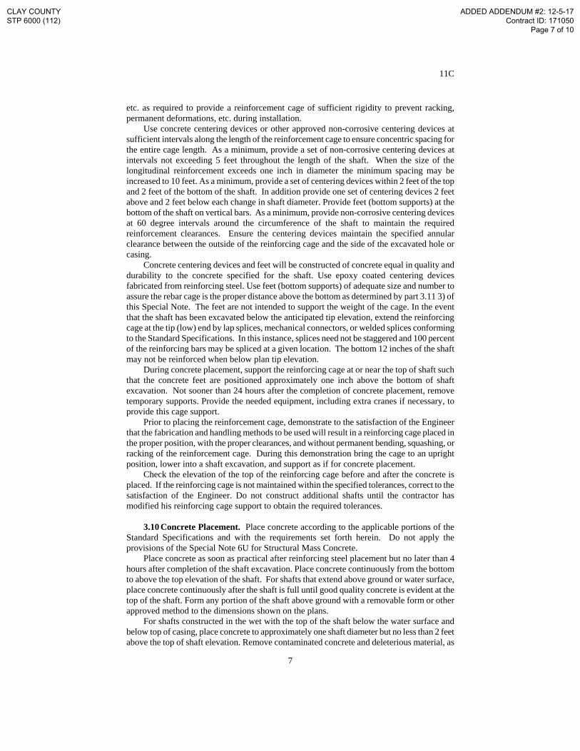
etc. as required to provide a reinforcement cage of sufficient rigidity to prevent racking, permanent deformations, etc. during installation.
Use concrete centering devices or other approved non-corrosive centering devices at sufficient intervals along the length of the reinforcement cage to ensure concentric spacing for the entire cage length. As a minimum, provide a set of non-corrosive centering devices at intervals not exceeding 5 feet throughout the length of the shaft. When the size of the longitudinal reinforcement exceeds one inch in diameter the minimum spacing may be increased to 10 feet. As a minimum, provide a set of centering devices within 2 feet of the top and 2 feet of the bottom of the shaft. In addition provide one set of centering devices 2 feet above and 2 feet below each change in shaft diameter. Provide feet (bottom supports) at the bottom of the shaft on vertical bars. As a minimum, provide non-corrosive centering devices at 60 degree intervals around the circumference of the shaft to maintain the required reinforcement clearances. Ensure the centering devices maintain the specified annular clearance between the outside of the reinforcing cage and the side of the excavated hole or casing.
Concrete centering devices and feet will be constructed of concrete equal in quality and durability to the concrete specified for the shaft. Use epoxy coated centering devices fabricated from reinforcing steel. Use feet (bottom supports) of adequate size and number to assure the rebar cage is the proper distance above the bottom as determined by part 3.11 3) of this Special Note. The feet are not intended to support the weight of the cage. In the event that the shaft has been excavated below the anticipated tip elevation, extend the reinforcing cage at the tip (low) end by lap splices, mechanical connectors, or welded splices conforming to the Standard Specifications. In this instance, splices need not be staggered and 100 percent of the reinforcing bars may be spliced at a given location. The bottom 12 inches of the shaft may not be reinforced when below plan tip elevation.
During concrete placement, support the reinforcing cage at or near the top of shaft such that the concrete feet are positioned approximately one inch above the bottom of shaft excavation. Not sooner than 24 hours after the completion of concrete placement, remove temporary supports. Provide the needed equipment, including extra cranes if necessary, to provide this cage support.
Prior to placing the reinforcement cage, demonstrate to the satisfaction of the Engineer that the fabrication and handling methods to be used will result in a reinforcing cage placed in the proper position, with the proper clearances, and without permanent bending, squashing, or racking of the reinforcement cage. During this demonstration bring the cage to an upright position, lower into a shaft excavation, and support as if for concrete placement.
Check the elevation of the top of the reinforcing cage before and after the concrete is placed. If the reinforcing cage is not maintained within the specified tolerances, correct to the satisfaction of the Engineer. Do not construct additional shafts until the contractor has modified his reinforcing cage support to obtain the required tolerances.
3.10 Concrete Placement. Place concrete according to the applicable portions of the
Standard Specifications and with the requirements set forth herein. Do not apply the provisions of the Special Note 6U for Structural Mass Concrete.
Place concrete as soon as practical after reinforcing steel placement but no later than 4 hours after completion of the shaft excavation. Place concrete continuously from the bottom to above the top elevation of the shaft. For shafts that extend above ground or water surface, place concrete continuously after the shaft is full until good quality concrete is evident at the top of the shaft. Form any portion of the shaft above ground with a removable form or other approved method to the dimensions shown on the plans.
For shafts constructed in the wet with the top of the shaft below the water surface and below top of casing, place concrete to approximately one shaft diameter but no less than 2 feet above the top of shaft elevation. Remove contaminated concrete and deleterious material, as
CLAY COUNTY STP 6000 (112)
ADDED ADDENDUM #2: 12-5-17 Contract ID: 171050
Page 7 of 10

11C
8
determined by the Engineer, accumulated above the top of shaft elevation immediately after completing concrete placement. Deleterious material and contaminated concrete may be airlifted under a head of water or slurry provided that the head is maintained at or near the exterior water surface elevation. Carefully remove any concrete remaining above plan top of shaft after curing and excess casing removal.
Place concrete either by free fall, through a tremie, or concrete pump. Use the free fall placement method in dry holes only. The maximum height of free fall placement is 20 feet. Do not allow concrete placed by free fall to contact either the reinforcing cage or hole sidewall. Drop chutes may be used to direct concrete to the base during free fall placement.
Place concrete in the shaft in one continuous operation. Maintain a minimum slump of 4 inches or more throughout the placement for 4 hours after batching. Adjust approved admixtures in the concrete mix for the conditions encountered on the job so that the concrete remains in a workable plastic state throughout the placement. Perform slump loss tests to demonstrate that the concrete will maintain a 4-inch or greater slump for a period of time equal to the estimated transport plus the 2-hour placement time, but not less than 4 hours.
When the Engineer determines the concrete placement methods and/or equipment during construction of any technique and/or production shafts to be inadequate, make appropriate alterations to eliminate unsatisfactory results.
Drilled shafts not meeting the concrete placement requirements of this Special Note or contract plans are unacceptable. Correct all unacceptable completed shafts to the satisfaction of the Engineer.
3.10.1 Tremie Placement. Tremies may be used for concrete placement in either wet or dry holes. Extend the tremie to the shaft base elevation before starting underwater placement. Valves, bottom plates, or plugs may be used only if concrete discharge can begin approximately 2 inches above the excavation bottom. Remove plugs from the excavation unless otherwise approved by the Engineer. Maintain tremie discharge at or near the bottom of excavation as long as practical during concrete placement. Immerse tremie discharge end as deep as practical in the concrete but not less than 10 feet.
If at any time during the concrete pour the tremie line orifice is removed from the fluid concrete column and discharges concrete above the rising concrete surface, the entire drilled shaft is considered defective. In such case, remove the reinforcing cage and concrete, complete any necessary sidewall cleaning or over-reaming as directed by the Engineer, and repour the shaft.
3.10.2 Pumped Concrete. Concrete pumps and lines may be used for concrete
placement in either wet or dry excavations. Do not begin concrete placement until the pump line discharge orifice is at the shaft base elevation.
For wet excavations, use a plug or similar device to separate the concrete from the fluid in the hole until pumping begins. Remove the plug unless otherwise approved by the engineer.
Ensure the discharge orifice remains at least 10 feet below the surface of the fluid concrete. When lifting the pump line during concrete placement, reduce the line pressure until the orifice has been repositioned at a higher level in the excavation.
If at any time during the concrete pour the pump line orifice is removed from the fluid concrete column and discharges concrete above the rising concrete level, the Department will consider the shaft defective. In such case, remove the reinforcing cage and concrete, complete any necessary sidewall cleaning or over-reaming as the Engineer directs, and repour the shaft.
CLAY COUNTY STP 6000 (112)
ADDED ADDENDUM #2: 12-5-17 Contract ID: 171050
Page 8 of 10

11C
9
3.10.3 Drop Chutes. Drop chutes may be used to direct placement of free fall concrete in excavations where the maximum depth of water does not exceed one inch. Do not use the free fall method of placement in wet excavations. Concrete may be placed through either a hopper at the top of the tube or side openings as the drop chute is retrieved during concrete placement. Reduce the height of free fall and/or reduce the rate of concrete flow into the excavation if the concrete placement causes the shaft excavation to cave or slough, or if the concrete strikes the reinforcing cage or sidewall. When the Engineer determines free fall placement cannot be accomplished satisfactorily, use either tremie or pumping to accomplish the pour.
3.11 Construction Tolerances. The following construction tolerances apply to drilled
shafts unless otherwise stated in the contract document:
1) Construct drilled shaft within 3 inches of plan position in the horizontal plane at the top of the shaft.
2) Do not vary the vertical alignment of a shaft excavation from the plan alignment by more than 1/4 inch per foot of depth or 6 inches total.
3) Maintain the top of the reinforcing steel cage no more than 6 inches above and no more than 3 inches below plan position.
4) All casing diameters shown on the plans refer to O.D. (outside diameter) dimensions. The casing dimensions are subject to American Pipe Institute tolerances applicable to regular steel pipe. A casing larger in diameter than shown in the plans may be used, at no additional cost, with prior approval by the Department.
5) Maintain the top of shaft concrete within 3 inches from the plan top of shaft elevation, measured after excess shaft concrete has been removed.
6) Design excavation equipment and methods so that the completed shaft excavation will have a planar bottom. Maintain the cutting edges of excavation equipment normal to the vertical axis of the equipment within a tolerance of ± 3/8 inch per foot of diameter. The tip elevation of the shaft has a tolerance of ± 6 inches from final shaft tip elevation unless otherwise specified in the plans.
Drilled shaft excavations and completed shafts not constructed within the required
tolerances are unacceptable. Correct all unacceptable shaft excavations and completed shafts to the satisfaction of the Engineer. When a shaft excavation is completed with unacceptable tolerances, present corrective measures designed by a registered Professional Engineer for approval. 4.0 MEASUREMENT.
4.1 Drilled Shafts. The Department will not measure for payment any trial batches required to demonstrate the adequacy of the concrete mix, method, or equipment; concrete required to fill an oversized casing or oversized excavation; obstruction removal; over-reaming or sidewall cleaning; inspection work or inspection equipment; materials or work necessary, including engineering analyses and redesign, to alter unacceptable work methods or to complete corrections for unacceptable work; and will consider them incidental to the Drilled Shaft. Unless noted otherwise in the contract documents, casing is incidental to the drilled shaft.
4.1.1 Drilled Shaft, Common. The Department will measure the length, in linear feet,
of drilled shaft above the top of rock elevation shown on the plans. The
CLAY COUNTY STP 6000 (112)
ADDED ADDENDUM #2: 12-5-17 Contract ID: 171050
Page 9 of 10

11C
10
Department will consider this quantity Drilled Shaft, Common regardless of the character of material actually encountered.
4.1.2 Drilled Shafts, Solid Rock. The Department will measure the length, in linear
feet, of drilled shaft below the top of rock elevation shown on plans. The Department will consider this quantity Drilled Shafts, Solid Rock regardless of the character of material actually encountered during excavation.
4.2 Technique Shaft. The Department will pay for technique shaft at the contract unit
price per each as detailed on the plans or as directed by the Engineer. This will constitute full compensation for all costs incurred during installation as described herein for ‘Drilled Shaft’ or in the contract documents. No additional compensation beyond the number of technique shafts allowed for in the plans will be permitted for additional technique shafts required because of failure to demonstrate adequacy of methods.
4.3 Rock Coring and Rock Sounding. The Department will measure Rock Sounding
and Rock Coring shown on the plans, as specified in part 3.5 of this Special Note, and as the Engineer directs, in linear feet to the nearest 0.1-foot. If soil samples are specified in the contract documents they will be incidental to the unit price bid for Rock Sounding. The Department will not measure or pay for subsurface exploration performed deeper than the elevations indicated on the plans and/or in this Special Note, unless directed by the Engineer, and will consider it incidental to these items of work. Additionally, the Department will consider all mobilization, equipment, labor, incidental items, and operations necessary to complete the boring operations incidental to these items of work.
5.0 PAYMENT. The Department will make payment for the completed and accepted quantities under the following: Code Pay Item Pay Unit ----- Drilled Shaft, Diameter*, Common Linear Foot ----- Drilled Shaft, Diameter*, Solid Rock Linear Foot ----- Technique Shaft Each 20745ED Rock Sounding Linear Foot 20746ED Rock Coring Linear Foot * See Plan Sheets for sizes of shafts.
The Department will consider payment as full compensation for all work required in this
note.
June 15, 2012
CLAY COUNTY STP 6000 (112)
ADDED ADDENDUM #2: 12-5-17 Contract ID: 171050
Page 10 of 10

PROPOSAL BID ITEMS
Report Date 12/5/17Page 1 of 7
171050
Section: 0001 - PAVINGLINE BID CODE ALT DESCRIPTION QUANTITY UNIT UNIT PRIC FP AMOUNT0010 00003 CRUSHED STONE BASE 22,680.00 TON $0020 00020 TRAFFIC BOUND BASE 500.00 TON $0030 00100 ASPHALT SEAL AGGREGATE 59.00 TON $0040 00103 ASPHALT SEAL COAT 8.00 TON $0050 00190 LEVELING & WEDGING PG64-22 328.00 TON $0060 00212 CL2 ASPH BASE 1.00D PG64-22 15,185.00 TON $0070 00301 CL2 ASPH SURF 0.38D PG64-22 4,760.00 TON $0080 02101 CEM CONC ENT PAVEMENT-8 IN 359.00 SQYD $
0090 24780ECINTELLIGENT COMPACTION FORAGGREGATE 42,953.00 TON $
0100 24781EC INTELLIGENT COMPACTION FOR ASPHALT 42,953.00 TON $0110 24891EC PAVE MOUNT INFRARED TEMP EQUIPMENT 545,967.00 SF $0120 24966EC RUBBER PAVEMENT 0.5 IN 847.00 SQYD $
Section: 0002 - ROADWAYLINE BID CODE ALT DESCRIPTION QUANTITY UNIT UNIT PRIC FP AMOUNT0390 00078 CRUSHED AGGREGATE SIZE NO 2 1,037.00 TON $0400 01000 PERFORATED PIPE-4 IN 1,463.00 LF $0410 01005 PERFORATED PIPE EDGE DRAIN-4 IN 7,978.00 LF $0420 01006 PERFORATED PIPE EDGE DRAIN-6 IN 572.00 LF $0430 01010 NON-PERFORATED PIPE-4 IN 469.00 LF $0440 01015 INSPECT & CERTIFY EDGE DRAIN SYSTEM 1.00 LS $0450 01020 PERF PIPE HEADWALL TY 1-4 IN 19.00 EACH $0460 01022 PERF PIPE HEADWALL TY 1-8 IN 8.00 EACH $0470 01028 PERF PIPE HEADWALL TY 3-4 IN 8.00 EACH $0480 01740 CORED HOLE DRAINAGE BOX CON-4 IN 55.00 EACH $0490 01741 CORED HOLE DRAINAGE BOX CON-6 IN 1.00 EACH $0500 01810 STANDARD CURB AND GUTTER 13,096.00 LF $0510 01875 STANDARD HEADER CURB 1,080.00 LF $
0520 01987DELINEATOR FOR GUARDRAIL BIDIRECTIONAL WHITE 72.00 EACH $
0530 02014 BARRICADE-TYPE III 30.00 EACH $0540 02091 REMOVE PAVEMENT 8,057.00 SQYD $0550 02159 TEMP DITCH 4,513.00 LF $0560 02160 CLEAN TEMP DITCH 2,256.00 LF $0570 02165 REMOVE PAVED DITCH 12.00 SQYD $0580 02200 ROADWAY EXCAVATION 930,485.00 CUYD $0590 02242 WATER 342.00 MGAL $0600 02351 GUARDRAIL-STEEL W BEAM-S FACE 5,912.50 LF $0610 02360 GUARDRAIL TERMINAL SECTION NO 1 14.00 EACH $
0620 02363GUARDRAIL CONNECTOR TO BRIDGE ENDTY A 3.00 EACH $
0630 02371 GUARDRAIL END TREATMENT TYPE 7 3.00 EACH $0640 02381 REMOVE GUARDRAIL 433.00 LF $0650 02391 GUARDRAIL END TREATMENT TYPE 4A 11.00 EACH $0660 02429 RIGHT-OF-WAY MONUMENT TYPE 1 121.00 EACH $
CLAY COUNTYSTP 6000 (112)
Contract ID: 171050Page 217 of 222
REVISED ADDENDUM #2: 12-5-17

PROPOSAL BID ITEMS
Report Date 12/5/17Page 2 of 7
171050
LINE BID CODE ALT DESCRIPTION QUANTITY UNIT UNIT PRIC FP AMOUNT0670 02432 WITNESS POST 3.00 EACH $0680 02482 CHANNEL LINING CLASS IA 68.00 TON $0690 02488 CHANNEL LINING CLASS IV 5,563.00 CUYD $
0700 02545CLEARING AND GRUBBING 49 ACRES 1.00 LS $
0710 02551 CONCRETE-CLASS A FOR STEPS 2.20 CUYD $0720 02562 TEMPORARY SIGNS 3,445.00 SQFT $0730 02598 FABRIC-GEOTEXTILE TYPE III 900.00 SQYD $0740 02599 FABRIC-GEOTEXTILE TYPE IV 52,556.00 SQYD $0750 02600 FABRIC GEOTEXTILE TY IV FOR PIPE 12,487.00 SQYD $2.00 $ $24,974.000760 02611 HANDRAIL-TYPE A-1 22.00 LF $0770 02650 MAINTAIN & CONTROL TRAFFIC 1.00 LS $
0780 02651DIVERSIONS (BY-PASS DETOURS)DIVERSION #1 1.00 LS $
0790 02651DIVERSIONS (BY-PASS DETOURS)DIVERSION #2 1.00 LS $
0800 02671 PORTABLE CHANGEABLE MESSAGE SIGN 4.00 EACH $0810 02676 MOBILIZATION FOR MILL & TEXT 1.00 LS $0820 02677 ASPHALT PAVE MILLING & TEXTURING 477.00 TON $0830 02701 TEMP SILT FENCE 4,513.00 LF $0840 02703 SILT TRAP TYPE A 49.00 EACH $0850 02704 SILT TRAP TYPE B 49.00 EACH $0860 02705 SILT TRAP TYPE C 49.00 EACH $0870 02706 CLEAN SILT TRAP TYPE A 49.00 EACH $0880 02707 CLEAN SILT TRAP TYPE B 49.00 EACH $0890 02708 CLEAN SILT TRAP TYPE C 49.00 EACH $0900 02720 SIDEWALK-4 IN CONCRETE 7,085.00 SQYD $0910 02721 REMOVE CONCRETE SIDEWALK 84.00 SQYD $0920 02726 STAKING 1.00 LS $
0930 02731REMOVE STRUCTURECOAL HOLLOW RD. BRIDGE 1.00 LS $
0940 02731REMOVE STRUCTUREGOOSE CREEK BRIDGE 1.00 LS $
0950 02731REMOVE STRUCTUREKY 2432 HART BRANCH BRIDGE 1.00 LS $
0960 02775 ARROW PANEL 2.00 EACH $0970 05950 EROSION CONTROL BLANKET 38,917.00 SQYD $0980 05952 TEMP MULCH 158,155.00 SQYD $0990 05953 TEMP SEEDING AND PROTECTION 118,616.00 SQYD $1000 05963 INITIAL FERTILIZER 2.00 TON $1010 05964 20-10-10 FERTILIZER 10.60 TON $1020 05985 SEEDING AND PROTECTION 146,640.00 SQYD $1030 05990 SODDING 18,555.00 SQYD $1040 05992 AGRICULTURAL LIMESTONE 91.00 TON $1050 06510 PAVE STRIPING-TEMP PAINT-4 IN 50,249.00 LF $1060 06514 PAVE STRIPING-PERM PAINT-4 IN 50,249.00 LF $1070 06566 PAVE MARKING-THERMO X-WALK-12 IN 1,510.00 LF $1080 06568 PAVE MARKING-THERMO STOP BAR-24IN 322.00 LF $1090 06569 PAVE MARKING-THERMO CROSS-HATCH 648.00 SQFT $1100 06574 PAVE MARKING-THERMO CURV ARROW 19.00 EACH $1110 10020NS FUEL ADJUSTMENT 232,797.00 DOLL $1.00 $ $232,797.001120 10030NS ASPHALT ADJUSTMENT 76,472.00 DOLL $1.00 $ $76,472.00
CLAY COUNTYSTP 6000 (112)
Contract ID: 171050Page 218 of 222
REVISED ADDENDUM #2: 12-5-17

PROPOSAL BID ITEMS
Report Date 12/5/17Page 3 of 7
171050
LINE BID CODE ALT DESCRIPTION QUANTITY UNIT UNIT PRIC FP AMOUNT1130 20206EC PAVE MARK HANDICAP SYMBOL 7.00 EACH $1140 20430ED SAW CUT 2,326.00 LF $1150 23158ES505 DETECTABLE WARNINGS 875.00 SQFT $1160 24489EC INLAID PAVEMENT MARKER 51.00 EACH $1170 24540 R/W MONUMENT TYPE 3 11.00 EACH $1180 24805ED OBJECT MARKER TYPE 4 3.00 EACH $
Section: 0003 - DRAINAGELINE BID CODE ALT DESCRIPTION QUANTITY UNIT UNIT PRIC FP AMOUNT1200 00440 ENTRANCE PIPE-15 IN 207.00 LF $1210 00441 ENTRANCE PIPE-18 IN 274.00 LF $1220 00443 ENTRANCE PIPE-24 IN 254.00 LF $1230 00461 CULVERT PIPE-15 IN 84.00 LF $1240 00462 CULVERT PIPE-18 IN 95.00 LF $1250 00464 CULVERT PIPE-24 IN 460.00 LF $1260 00466 CULVERT PIPE-30 IN 178.00 LF $1270 00468 CULVERT PIPE-36 IN 332.00 LF $1280 00469 CULVERT PIPE-42 IN 52.00 LF $1290 00470 CULVERT PIPE-48 IN 80.00 LF $1300 00521 STORM SEWER PIPE-15 IN 2,355.00 LF $1310 00522 STORM SEWER PIPE-18 IN 1,726.00 LF $1320 00524 STORM SEWER PIPE-24 IN 735.00 LF $1330 01202 PIPE CULVERT HEADWALL-15 IN 4.00 EACH $1340 01204 PIPE CULVERT HEADWALL-18 IN 9.00 EACH $1350 01208 PIPE CULVERT HEADWALL-24 IN 7.00 EACH $1360 01210 PIPE CULVERT HEADWALL-30 IN 2.00 EACH $1370 01212 PIPE CULVERT HEADWALL-36 IN 4.00 EACH $1380 01216 PIPE CULVERT HEADWALL-48 IN 2.00 EACH $1390 01396 METAL END SECTION TY 3-42 IN 2.00 EACH $1400 01410 METAL END SECTION TY 4-15 IN 1.00 EACH $1410 01432 SLOPED BOX OUTLET TYPE 1-15 IN 3.00 EACH $1420 01433 SLOPED BOX OUTLET TYPE 1-18 IN 2.00 EACH $1430 01434 SLOPED BOX OUTLET TYPE 1-24 IN 1.00 EACH $1440 01450 S & F BOX INLET-OUTLET-18 IN 1.00 EACH $1450 01451 S & F BOX INLET-OUTLET-24 IN 3.00 EACH $1460 01452 S & F BOX INLET-OUTLET-30 IN 2.00 EACH $1470 01456 CURB BOX INLET TYPE A 50.00 EACH $1480 01496 DROP BOX INLET TYPE 3 2.00 EACH $1490 01577 DROP BOX INLET TYPE 14 6.00 EACH $1500 20098NC CAP BOX INLET 1.00 EACH $
1510 24575ES610HEADWALL3X36 2.00 EACH $
1520 24814EC PIPELINE INSPECTION 4,438.00 LF $
Section: 0004 - BRIDGE-GOOSE CREEK - DRAWING #27581LINE BID CODE ALT DESCRIPTION QUANTITY UNIT UNIT PRIC FP AMOUNT
CLAY COUNTYSTP 6000 (112)
Contract ID: 171050Page 219 of 222
REVISED ADDENDUM #2: 12-5-17

PROPOSAL BID ITEMS
Report Date 12/5/17Page 4 of 7
171050
LINE BID CODE ALT DESCRIPTION QUANTITY UNIT UNIT PRIC FP AMOUNT1530 02231 STRUCTURE GRANULAR BACKFILL 250.00 CUYD $1540 02998 MASONRY COATING 957.20 SQYD $1550 03299 ARMORED EDGE FOR CONCRETE 93.00 LF $1560 08001 STRUCTURE EXCAVATION-COMMON 134.00 CUYD $1570 08019 CYCLOPEAN STONE RIP RAP 2,065.00 TON $1580 08033 TEST PILES 48.00 LF $1590 08039 PRE-DRILLING FOR PILES 70.00 LF $1600 08050 PILES-STEEL HP14X73 225.00 LF $1610 08095 PILE POINTS-14 IN 14.00 EACH $1620 08100 CONCRETE-CLASS A 276.60 CUYD $1630 08104 CONCRETE-CLASS AA 655.70 CUYD $
1640 08150STEEL REINFORCEMENT(REVISED: 12-5-17) 49,919.00 LB $
1650 08151 STEEL REINFORCEMENT-EPOXY COATED 108,849.00 LB $1660 08633 PRECAST PC I BEAM TYPE 3 968.00 LF $1670 08635 PRECAST PC I BEAM TYPE 6 873.00 LF $1680 20637ED DRILLED SHAFT-ROCK 48 IN 60.00 LF $
1685 20745EDROCK SOUNDINGS(ADDED: 12-5-17) 88.00 LF $
1686 20746EDROCK CORINGS(ADDED: 12-5-17) 156.00 LF $
1690 21119ED CONCRETE FORM LINER 732.00 SQYD $1700 21777EN DRILLED SHAFT COMMON-54 IN 86.00 LF $1710 23168ED CONCRETE STAINING 937.00 SQYD $1720 23813EC DECK DRAIN 22.00 EACH $
Section: 0005 - BRIDGE-CULVERT-HART BRANCH - DRAWING #27582LINE BID CODE ALT DESCRIPTION QUANTITY UNIT UNIT PRIC FP AMOUNT1730 08001 STRUCTURE EXCAVATION-COMMON 894.00 CUYD $1740 08002 STRUCTURE EXCAV-SOLID ROCK 277.00 CUYD $1750 08100 CONCRETE-CLASS A 1,410.00 CUYD $1760 08150 STEEL REINFORCEMENT 127,845.00 LB $
Section: 0006 - BRIDGE-CULVERT-COAL HOLLOW - DRAWING #27583LINE BID CODE ALT DESCRIPTION QUANTITY UNIT UNIT PRIC FP AMOUNT1770 08001 STRUCTURE EXCAVATION-COMMON 432.00 CUYD $1780 08002 STRUCTURE EXCAV-SOLID ROCK 161.00 CUYD $1790 08100 CONCRETE-CLASS A 423.00 CUYD $1800 08150 STEEL REINFORCEMENT 34,039.00 LB $
Section: 0007 - BRIDGE- RETAINING WALL - KY 2432 - DRAWING #27606LINE BID CODE ALT DESCRIPTION QUANTITY UNIT UNIT PRIC FP AMOUNT1810 02203 STRUCTURE EXCAV-UNCLASSIFIED 307.00 CUYD $1820 02555 CONCRETE-CLASS B 352.00 CUYD $
CLAY COUNTYSTP 6000 (112)
Contract ID: 171050Page 220 of 222
REVISED ADDENDUM #2: 12-5-17

PROPOSAL BID ITEMS
Report Date 12/5/17Page 5 of 7
171050
LINE BID CODE ALT DESCRIPTION QUANTITY UNIT UNIT PRIC FP AMOUNT
1830 02599FABRIC-GEOTEXTILE TYPE IV(REVISED: 12-5-17) 460.00 SQYD $
1840 02611 HANDRAIL-TYPE A-1 325.00 LF $1850 21119ED CONCRETE FORM LINER 175.00 SQYD $1860 23168ED CONCRETE STAINING 211.00 SQYD $1870 24596EN GRANULAR BACKFILL 488.00 CUYD $
Section: 0008 - BRIDGE-RETAINING WALL - KY 2432 - DRAWING #27605LINE BID CODE ALT DESCRIPTION QUANTITY UNIT UNIT PRIC FP AMOUNT1880 02203 STRUCTURE EXCAV-UNCLASSIFIED 311.00 CUYD $
1885 02555CONCRETE-CLASS B(ADDED: 12-5-17) 359.00 CUYD $
1890 02611 HANDRAIL-TYPE A-1 195.00 LF $1900 21119ED CONCRETE FORM LINER 158.00 SQYD $1910 23168ED CONCRETE STAINING 180.00 SQYD $
Section: 0009 - UTILITY-WATER-SEWER-GAS (ADDED: 11-22-17)LINE BID CODE ALT DESCRIPTION QUANTITY UNIT UNIT PRIC FP AMOUNT1920 14003 W CAP EXISTING MAIN 2.00 EACH $1930 14005 W ENCASEMENT CONCRETE 500.00 LF $
1940 14007W ENCASEMENT STEEL BORED RANGE 210 IN 20.00 LF $
1950 14008W ENCASEMENT STEEL BORED RANGE 312 IN 80.00 LF $
1960 14009 W ENCASEMENT STEEL BORED RANGE 4 185.00 LF $
1970 14010W ENCASEMENT STEEL BORED RANGE 524 IN 30.00 LF $
1980 14014W ENCASEMENT STEEL OPEN CUT RANGE 312 IN 295.00 LF $
1990 14016W ENCASEMENT STEEL OPEN CUT RANGE 524 IN 435.00 LF $
2000 14019 W FIRE HYDRANT ASSEMBLY 16.00 EACH $2010 14028 W METER 3/4 INCH 9.00 EACH $
2020 14030W METER RELOCATERECONNECT 1.00 EACH $
2030 14037 W PIPE DUCTILE IRON 08 INCH 4,690.00 LF $2040 14039 W PIPE DUCTILE IRON 12 INCH 4,320.00 LF $2050 14060 W PIPE PVC 08 INCH 2,000.00 LF $2060 14071 W PIPE POLYETHYLENE/PLASTIC 10 INCH 2,235.00 LF $
2070 14073W PIPE POLYETHYLENE/PLASTIC SPECIAL18 IN 1,540.00 LF $
2080 14080 W SERV PE/PLST LONG SIDE 3/4 IN 9.00 EACH $2090 14089 W TAPPING SLEEVE AND VALVE SIZE 1 11.00 EACH $2100 14090 W TAPPING SLEEVE AND VALVE SIZE 2 4.00 EACH $2110 14094 W TIE-IN 06 INCH 1.00 EACH $2120 14095 W TIE-IN 08 INCH 5.00 EACH $2130 14097 W TIE-IN 12 INCH 4.00 EACH $2140 14106 W VALVE 08 INCH 12.00 EACH $
CLAY COUNTYSTP 6000 (112)
Contract ID: 171050Page 221 of 222
REVISED ADDENDUM #2: 12-5-17

PROPOSAL BID ITEMS
Report Date 12/5/17Page 6 of 7
171050
LINE BID CODE ALT DESCRIPTION QUANTITY UNIT UNIT PRIC FP AMOUNT2150 14108 W VALVE 12 INCH 1.00 EACH $
2160 14126W ENCASEMENT SPECIAL16 IN-DIRECTIONAL BORE 805.00 LF $
2170 14126W ENCASEMENT SPECIAL16 IN-OPEN CUT 1,030.00 LF $
2180 14126W ENCASEMENT SPECIAL2 IN-DIRECTIONAL BORE 448.00 LF $
2190 14126W ENCASEMENT SPECIAL2 IN-OPEN CUT 541.00 LF $
2200 14126W ENCASEMENT SPECIAL24 IN -DIRECTIONAL BORE 435.00 LF $
2210 14126W ENCASEMENT SPECIAL5 IN-DIRECTIONAL BORE 297.00 LF $
2220 14126W ENCASEMENT SPECIAL8 IN-OPEN CUT 165.00 LF $
2230 15051S FORCE MAIN PE/PLASTIC 04 INCH4 IN 185.00 LF $
2240 15059 S FORCE MAIN PVC 04 INCH 90.00 LF $
2250 15068S FORCE MAIN SPECIAL14 IN 305.00 LF $
2260 15073 S FORCE MAIN TIE-IN 04 INCH 1.00 EACH $2270 15092 S MANHOLE 13.00 EACH $2280 15093 S MANHOLE ABANDON/REMOVE 5.00 EACH $2290 15094 S MANHOLE ADJUST TO GRADE 15.00 EACH $2300 15112 S PIPE PVC 08 INCH 1,252.00 LF $2310 15119 S PUMP STATION 1.00 EACH $2320 15122 S STRUCTURE REMOVAL 1.00 EACH $2330 16015 G PIPE POLYETHYLENE/PLASTIC 02 INCH 310.00 LF $2340 16048 G TIE-IN SPECIAL 2.00 EACH $2350 16049 G VALVE POLYETHYLENE/PLASTIC 02 INCH 2.00 EACH $2360 16056 G VALVE SPECIAL 4.00 EACH $2370 16057 G VALVE STEEL 02 INCH 4.00 EACH $2380 16110 G PIPE POLYETHYLENE/PLASTIC 01 INCH 235.00 LF $2390 21233ED ASPHALT PAVING REPLACEMENT 430.00 LF $
2400 23667ECWATER MAIN CREEK CROSSING16 IN 240.00 LF $
2410 23667ECWATER MAIN CREEK CROSSING24 IN 480.00 LF $
2420 24441EC GRAVEL REPLACEMENT DRIVEWAYS 130.00 LF $
Section: 0010 - SIGNALIZATIONLINE BID CODE ALT DESCRIPTION QUANTITY UNIT UNIT PRIC FP AMOUNT0130 04792 CONDUIT-1 IN 50.00 LF $0140 04795 CONDUIT-2 IN 200.00 LF $0150 04820 TRENCHING AND BACKFILLING 100.00 LF $0160 04830 LOOP WIRE 1,650.00 LF $0170 04844 CABLE-NO. 14/5C 2,700.00 LF $0180 04850 CABLE-NO. 14/1 PAIR 1,000.00 LF $0190 04885 MESSENGER-10800 LB 400.00 LF $0200 04895 LOOP SAW SLOT AND FILL 620.00 LF $
CLAY COUNTYSTP 6000 (112)
Contract ID: 171050Page 222 of 222
REVISED ADDENDUM #2: 12-5-17

PROPOSAL BID ITEMS
Report Date 12/5/17Page 7 of 7
171050
LINE BID CODE ALT DESCRIPTION QUANTITY UNIT UNIT PRIC FP AMOUNT0210 04931 INSTALL CONTROLLER TYPE 170 1.00 EACH $0220 04932 INSTALL STEEL STRAIN POLE 4.00 EACH $0230 20093NS835 INSTALL PEDESTRIAN HEAD-LED 8.00 EACH $0240 20188NS835 INSTALL LED SIGNAL-3 SECTION 8.00 EACH $0250 20266ES835 INSTALL LED SIGNAL- 4 SECTION 2.00 EACH $0260 21743NN INSTALL PEDESTRIAN DETECTOR 8.00 EACH $0270 23157EN TRAFFIC SIGNAL POLE BASE 17.00 CUYD $0280 23235EC INSTALL PEDESTAL POST 4.00 EACH $0290 23982EC INSTALL ANTENNA 1.00 EACH $0300 24955ED REMOVE SIGNAL EQUIPMENT 1.00 EACH $
Section: 0011 - LIGHTINGLINE BID CODE ALT DESCRIPTION QUANTITY UNIT UNIT PRIC FP AMOUNT0310 04740 POLE BASE 14.00 EACH $0320 04795 CONDUIT-2 IN 340.00 LF $0330 04820 TRENCHING AND BACKFILLING 2,600.00 LF $0340 20391NS835 ELECTRICAL JUNCTION BOX TYPE A 6.00 EACH $0350 21543EN BORE AND JACK CONDUIT 200.00 LF $0360 24901EC PVC CONDUIT-2 IN-SCHEDULE 80 2,800.00 LF $
Section: 0012 - DEMOBILIZATION &/OR MOBILIZATIONLINE BID CODE ALT DESCRIPTION QUANTITY UNIT UNIT PRIC FP AMOUNT0370 02568 MOBILIZATION 1.00 LS $0380 02569 DEMOBILIZATION 1.00 LS $
CLAY COUNTY STP 6000 (112)
Contract ID: 171050 Page 222(a) of 222
REVISED ADDENDUM #2: 12-5-17

KY 2432
RO
AD
RIC
HM
ON
D
CO
NN
ECTO
R
CO
OL SPRIN
GS
GREEN ST.
RO
AD
CO
OL SPRIN
GS
DRIV
E
ME
MO
RIA
L
DRIV
E
LA
NG
DO
N
MA
RIE
CO
NN
ECTO
R
KY 2432
AVE.
MA
RC
UM
JO
NES ST.
RO
AD
COTTO
N
BEN
D
RO
AD
CO
AL H
OLLO
W
EN
TR
AN
CES
TOTALS
AS ESTIMATED BY THE DESIGNER.
PROBABLE AMOUNT OF EROSION CONTROL FEATURES
EROSION CONTROL QUANTITIES ARE BASED ON THE
EARTHWORK CALCULATIONS:
EMBANKMENT:
EXCAVATION:
3421 CUYD #18
10000 CUYD #10, 372 CUYD #13,
GEOTECH NOTES:
*INCLUDES THE FOLLOWING FROM
1
2
3
4
1
22
109
ENGINEER
AND/OR AS DIRECTED BY THE
FOR USE ON RESIDENTIAL LOTS 6
RICHMOND RD. INTERSECTION
KY 3472 MEMORIAL DRIVE/US 421
FOR ALL SIGNAL EQUIPMENT AT THE
(70'X100'X70') OVER GOOSE CREEK
FOR REMOVAL OF KY 3472 BRIDGE
WIDE FLANGE STEEL BEAM BRIDGE
FOR REMOVAL OF KY 2432
WIDE FLANGE STEEL BEAM BRIDGE
FOR REMOVAL OF COAL HOLLOW RD.
7
5
3
30
143
105
WEB
B ST.
6592 CUYD PROFILE BENCHING
21916 CUYD DIT. EXC.**
659805 CUYD ROCK EXC.
241672 CUYD COM. EXC.
733147 CUYD EXC. AVAILABLE
929985 CUYD TOTAL EXCAVATION
FROM PIPE SUMMARY
**INCLUDES 289 CUYD
196838 CUYD EMB. TOTAL
8817 CUYD EMB. BENCHING
28854 CUYD RRB
13793 CUYD ROCK EMB.*
145374 CUYD EMB.
PARCEL 58 ENT.
GREEN ST. INCLUDES 102 LF FROM
24
140
26
150
229
32
144
5
18
111
7
6
5
4
3
2
1
19
985
4
324
18
141
3374
3374
220
52
26
142
1455
1455
118
51
243
1026
7
64
449
3936
3936
2
1
162
180
69
2
315
14
106
220
220
34
8
LINING
PROTECTION 3458 SQYD FOR DITCH
INCLUDES 35459 SQYD FOR SLOPE
EROSION CONTROL QUANTITY
OR STEEPER
FOR SLOPE PROTECTION FOR SLOPES 3:1
ALSO INCLUDED IN TOTALS 35459 SQYD
121 SQYD FOR PARCEL 14 SIDEWALK;
254 SQYD FOR PARK PATH
KY 2432 TOTALS INCLUDE:
561
2
52279
222397
12
162
28
95
41264
41264
91
18521
146640
10.6
2
118616
158155
2061
1
1
1
1
1
3
20
436
24805ED
24540
24489EC
23158ES505
20430ED
20206EC
10030NS
10020NS
6574
6569
6568
6566
6514
6510
5992
5990
5985
5964
5963
5953
5952
5950
4950
2775
2731
2731
2731
2726
OBJECT MARKER TYPE 4
R/W MONUMENT TYPE 3
INLAID PAVEMENT MARKERS
DETECTABLE WARNINGS
SAW CUT
PAVE MARK HANDICAP SYMBOL
ASPHALT ADJUSTMENT
FUEL ADJUSTMENT
PAVE MARKING-THERMO CURV ARROW
PAVE MARKING-THERMO CROSS-HATCH
PAVE MARKING-THERMO STOP BAR-24IN
PAVE MARKING-THERMO X-WALK-12 IN
PAVE STRIPING-PERM PAINT-4 IN
PAVE STRIPING-TEMP PAINT-4 IN
AGRICULTURAL LIMESTONE
SODDING
SEEDING AND PROTECTION
20-10-10 FERTILIZER
INITIAL FERTILIZER
TEMP SEEDING AND PROTECTION
TEMP MULCH
EROSION CONTROL BLANKET
REMOVE SIGNAL EQUIPMENT
ARROW PANEL
REMOVE STRUCTURE
REMOVE STRUCTURE
REMOVE STRUCTURE
STAKING
EACH
EACH
EACH
SQFT
LF
EACH
DOLL
DOLL
EACH
SQFT
LF
LF
LF
LF
TON
SQYD
SQYD
TON
TON
SQYD
SQYD
SQYD
EACH
EACH
LS
LS
LS
LS
3
11
51
875
2326
7
76472
232797
19
648
322
1510
50429
50249
91
18555
146640
10.6
2
118616
158155
38917
1
2
1
1
1
1
UNIT
GENERAL SUMMARY
DESCRIPTION
E-S
HE
ET
NA
ME:
R0020
LT
SMicro
Statio
n v8.11.9.829
COUNTY OF ITEM NO. SHEET NO.
CLAY 11-8001.00 R2L
GENERAL SUMMARY
ITEM NOTES:
Octo
ber 21, 2017
DA
TE P
LO
TT
ED:
bm
attin
gly
US
ER:
C:\
US
ER
S\
BM
AT
TIN
GL
Y.
GL
A-5
HP
KG
K2\
DES
KT
OP\
FIN
AL
CL
AY\
R0020
LT
S.
DG
NFIL
E
NA
ME:
gary.newton
Cloud
gary.newton
Line
gary.newton
Cloud
gary.newton
Line
gary.newton
Line
gary.newton
Line

KY 2432
RO
AD
RIC
HM
ON
D
CO
NN
ECTO
R
CO
OL SPRIN
GS
GREEN ST.
RO
AD
CO
OL SPRIN
GS
DRIV
E
ME
MO
RIA
L
DRIV
E
LA
NG
DO
N
MA
RIE
CO
NN
ECTO
R
KY 2432
AVE.
MA
RC
UM
JO
NES ST.
RO
AD
COTTO
N
BEN
D
RO
AD
CO
AL H
OLLO
W
EN
TR
AN
CES
TOTALS
AS ESTIMATED BY THE DESIGNER.
PROBABLE AMOUNT OF EROSION CONTROL FEATURES
EROSION CONTROL QUANTITIES ARE BASED ON THE
EARTHWORK CALCULATIONS:
EMBANKMENT:
EXCAVATION:
3421 CUYD #18
10000 CUYD #10, 372 CUYD #13,
GEOTECH NOTES:
*INCLUDES THE FOLLOWING FROM
1
2
3
1
22
109
ENGINEER
AND/OR AS DIRECTED BY THE
FOR USE ON RESIDENTIAL LOTS 6
(70'X100'X70') OVER GOOSE CREEK
FOR REMOVAL OF KY 3472 BRIDGE
WIDE FLANGE STEEL BEAM BRIDGE
FOR REMOVAL OF KY 2432
WIDE FLANGE STEEL BEAM BRIDGE
FOR REMOVAL OF COAL HOLLOW RD.
7
5
3
30
143
105
WEB
B ST.
6592 CUYD PROFILE BENCHING
21916 CUYD DIT. EXC.**
659805 CUYD ROCK EXC.
241672 CUYD COM. EXC.
733147 CUYD EXC. AVAILABLE
929985 CUYD TOTAL EXCAVATION
FROM PIPE SUMMARY
**INCLUDES 289 CUYD
196838 CUYD EMB. TOTAL
8817 CUYD EMB. BENCHING
28854 CUYD RRB
13793 CUYD ROCK EMB.*
145374 CUYD EMB.
PARCEL 58 ENT.
GREEN ST. INCLUDES 102 LF FROM
24
140
26
150
229
32
144
5
18
111
7
6
5
3
2
1
19
985
4
324
18
141
3374
3374
220
52
26
142
1455
1455
118
51
243
1026
7
64
449
3936
3936
2
1
162
180
69
2
315
14
106
220
220
34
8
LINING
PROTECTION 3458 SQYD FOR DITCH
INCLUDES 35459 SQYD FOR SLOPE
EROSION CONTROL QUANTITY
OR STEEPER
FOR SLOPE PROTECTION FOR SLOPES 3:1
ALSO INCLUDED IN TOTALS 35459 SQYD
121 SQYD FOR PARCEL 14 SIDEWALK;
254 SQYD FOR PARK PATH
KY 2432 TOTALS INCLUDE:
561
2
52279
222397
12
162
28
95
41264
41264
91
18521
146640
10.6
2
118616
158155
2061
1
1
1
1
3
20
436
24805ED
24540
24489EC
23158ES505
20430ED
20206EC
10030NS
10020NS
6574
6569
6568
6566
6514
6510
5992
5990
5985
5964
5963
5953
5952
5950
2775
2731
2731
2731
2726
OBJECT MARKER TYPE 4
R/W MONUMENT TYPE 3
INLAID PAVEMENT MARKERS
DETECTABLE WARNINGS
SAW CUT
PAVE MARK HANDICAP SYMBOL
ASPHALT ADJUSTMENT
FUEL ADJUSTMENT
PAVE MARKING-THERMO CURV ARROW
PAVE MARKING-THERMO CROSS-HATCH
PAVE MARKING-THERMO STOP BAR-24IN
PAVE MARKING-THERMO X-WALK-12 IN
PAVE STRIPING-PERM PAINT-4 IN
PAVE STRIPING-TEMP PAINT-4 IN
AGRICULTURAL LIMESTONE
SODDING
SEEDING AND PROTECTION
20-10-10 FERTILIZER
INITIAL FERTILIZER
TEMP SEEDING AND PROTECTION
TEMP MULCH
EROSION CONTROL BLANKET
ARROW PANEL
REMOVE STRUCTURE
REMOVE STRUCTURE
REMOVE STRUCTURE
STAKING
EACH
EACH
EACH
SQFT
LF
EACH
DOLL
DOLL
EACH
SQFT
LF
LF
LF
LF
TON
SQYD
SQYD
TON
TON
SQYD
SQYD
SQYD
EACH
LS
LS
LS
LS
3
11
51
875
2326
7
76472
232797
19
648
322
1510
50429
50249
91
18555
146640
10.6
2
118616
158155
38917
2
1
1
1
1
UNIT
GENERAL SUMMARY
DESCRIPTION
E-S
HE
ET
NA
ME:
R0020
LT
SMicro
Statio
n v8.11.9.829
COUNTY OF ITEM NO. SHEET NO.
CLAY 11-8001.00 R2L
GENERAL SUMMARY
ITEM NOTES:
Octo
ber 21, 2017
DA
TE P
LO
TT
ED:
bm
attin
gly
US
ER:
C:\
US
ER
S\
BM
AT
TIN
GL
Y.
GL
A-5
HP
KG
K2\
DES
KT
OP\
FIN
AL
CL
AY\
R0020
LT
S.
DG
NFIL
E
NA
ME:

PROFESSIONAL ENGINEERING
AMERICAN ENGINEERS, INC.www.aei.cc
(502) 245-3813Louisville, KY 40223
2500 Nelson Miller Parkway
E-S
HE
ET
NA
ME:
Micro
Statio
n v8.11.7.443
ITEM NUMBER
DRAWING NO.
SHEET NO.
Commonwealth of Kentucky
DEPARTMENT OF HIGHWAYSCOUNTY
ROUTE CROSSING
PREPARED BY
DETAILED BY:
DESIGNED BY:
DATE: CHECKED BY
REVISION DATE
11-8001
D. CARPENTER J. MILES
J. BURT J. MILES
CLAY
KY 2432 GOOSE CREEK
TITLE
S1
27581
9-29-2017
CO
NS
TR
UC
TIO
N
PR
OJ
EC
T
NO.
LE
TTIN
G
DA
TE
TRANSPORTATION CABINETDEPARTMENT OF HIGHWAYS
INDEX OF SHEETSSheet No. Description
SPECIAL NOTES
S1
GENERAL NOTES
LAYOUT
S2
S3
SPECIAL PROVISIONS
STANDARD DRAWINGS
SPECIFICATIONS
BGX-015-03 Bridge Drains
Construction.
2012 Standard Specifications for Road and Bridge
69 Embankment at Bridge End Bent Structures
Current Interims.
2010 AASHTO LRFD Bridge Design Specifications with
SOUNDING LAYOUT
ENDBENT #1
PIER #1
PIER #2
ENDBENT #2
FRAMING PLAN
FRAMING DETAILS
SUPERSTRUCTURE SLAB
SUPERSTRUCTURE DIAPHRAGM E.B. #1
SUPERSTRUCTURE DIAPHRAGM E.B.#2
SUPERSTRUCTURE BILL OF REINFORCEMENT
CONSTRUCTION ELEVATIONS
S6
S7
S8
S9
S10
S11
S12
S18
S19
S20
S21
T:\
KY
TC\13 P
ROJ
EC
TS\213-217
CL
AY
CO
KY 2432 IT
EM
11-8001\
ST
RU
CT
UR
ES\
ST
A. 52
+00
KY 2432
BRID
GE\
FIN
AL P
LA
NS\
S1-
TIT
LE.
DG
NFIL
E
NA
ME:
S4-S5
SPECIAL NOTE FOR DRILLED SHAFTS
BGX-006-10 Stencils for Structures
BBP-002-04 Bearing Details
BJE-001-13 Neoprene Expansion Dams and Armored Edges
BPS-009-08 HP14x73 Steel Pile
BGX-012-02 Geotechnical Legend
BBP-001-12 Elastomeric Bearing Pads for Prestressed Beams
Substr
ucture
Superstructure
BRIDGE TOTALS
UNIT
ITEM
BID
ESTIMATE OF QUANTITIES
125 14.3 119 15 70 60 7 31.4 3604 1286
146.8 15 77.1 17705 28 52 52 76
147.8 96.0 21663 32 34 36 80
125 14.3 33 165 7 31.4 3604 1280
634 93 40.7 655.7 3343 106283 968 873 22 425 630
250 957.2 93 134 48 70 225 14 276.6 655.7 49919 108849 968 873 22 86 88 156
BID ITEM CODE
END BENT #1
PIER #1
PIER #2
END BENT #2
C.Y.
Backfill
Gra
nular
Str
ucture
S.Y.
Coating
Masonry
0299802231
L.F.
for
Concrete
Arm
ore
d Edge
03299
Tons
Rip
Rap
Sto
ne
Cyclo
pean
C.Y.
Co
mm
on
Excavation,
Str
ucture
0801908001
L.F.
Test
Piles
08033
L.F.
08050
HP 14 x 73
Piles - Ste
el
EACH
08095
Pile Points 14
"
C.Y. C.Y. LBS.
Reinforc
em
ent
Ste
el
LBS.
Epoxy
Coate
d
Reinforc
em
ent,
Ste
el
Class "A"
Concrete
Class "A
A"
Concrete
08151081500810408100
LF.
08633
LF.
08635
Bea
m Type 3
Pre
cast
PC I
Bea
m Type 6
Pre
cast
PC I
S.Y.
21119ED
Form Lin
er
Concrete
LF.
Rock - 48 in.
Drilled Shaft
20637ED
EACH
Deck
Drains
23813EC
S.Y.
23168ED
Stainin
gConcrete
LF.
217777EN
54 in.
Co
mm
on -
Drilled Shaft
TITLE
BILL OF REINFORCEMENT
S13-S15
S16-S17 BEAM SHEET
S22-S23
S24-S25 ARCHITECTURAL FEATURES
S26 BARRIER WALL
L.F.
08039
for
Piles
Pre-Drillin
g
60
1094
971
2065 732
129
178
129
178
937
FOUNDATION LAYOUT
STA. 52+38.55
KY 2432 OVER GOOSE CREEK
CLAY COUNTY
1 QUANTITY ADDITION/REVISION 12/01/2017
LF. LF.
20745ED 20746ED
Soundin
g
Rock
Coring
Rock
Se
pte
mber 28, 2017
DA
TE P
LO
TT
ED:
sbriles
US
ER:
1 1
LANOIS
SE
FO
RP
KFOE
TA
TS
I
24485
JON A.
LSNEC
RE
ENI
GNE
YK
CUT
NE
MILES
ED

PROFESSIONAL ENGINEERING
AMERICAN ENGINEERS, INC.www.aei.cc
(502) 245-3813Louisville, KY 40223
2500 Nelson Miller Parkway
E-S
HE
ET
NA
ME:
Micro
Statio
n v8.11.7.443
ITEM NUMBER
DRAWING NO.
SHEET NO.
Commonwealth of Kentucky
DEPARTMENT OF HIGHWAYSCOUNTY
ROUTE CROSSING
PREPARED BY
DETAILED BY:
DESIGNED BY:
DATE: CHECKED BY
REVISION DATE
11-8001
D. CARPENTER J. MILES
J. BURT J. MILES
CLAY
KY 2432 GOOSE CREEK
TITLE
S1
27581
9-29-2017
CO
NS
TR
UC
TIO
N
PR
OJ
EC
T
NO.
LE
TTIN
G
DA
TE
TRANSPORTATION CABINETDEPARTMENT OF HIGHWAYS
INDEX OF SHEETSSheet No. Description
SPECIAL NOTES
S1
GENERAL NOTES
LAYOUT
S2
S3
SPECIAL PROVISIONS
STANDARD DRAWINGS
SPECIFICATIONS
BGX-015-03 Bridge Drains
Construction.
2012 Standard Specifications for Road and Bridge
69 Embankment at Bridge End Bent Structures
Current Interims.
2010 AASHTO LRFD Bridge Design Specifications with
SOUNDING LAYOUT
ENDBENT #1
PIER #1
PIER #2
ENDBENT #2
FRAMING PLAN
FRAMING DETAILS
SUPERSTRUCTURE SLAB
SUPERSTRUCTURE DIAPHRAGM E.B. #1
SUPERSTRUCTURE DIAPHRAGM E.B.#2
SUPERSTRUCTURE BILL OF REINFORCEMENT
CONSTRUCTION ELEVATIONS
S6
S7
S8
S9
S10
S11
S12
S18
S19
S20
S21
T:\
KY
TC\13 P
ROJ
EC
TS\213-217
CL
AY
CO
KY 2432 IT
EM
11-8001\
ST
RU
CT
UR
ES\
ST
A. 52
+00
KY 2432
BRID
GE\
FIN
AL P
LA
NS\
S1-
TIT
LE.
DG
NFIL
E
NA
ME:
S4-S5
SPECIAL NOTE FOR DRILLED SHAFTS
BGX-006-10 Stencils for Structures
BBP-002-04 Bearing Details
BJE-001-13 Neoprene Expansion Dams and Armored Edges
BPS-009-08 HP14x73 Steel Pile
BGX-012-02 Geotechnical Legend
BBP-001-12 Elastomeric Bearing Pads for Prestressed Beams
Substr
ucture
Superstructure
BRIDGE TOTALS
UNIT
ITEM
BID
ESTIMATE OF QUANTITIES
125 14.3 119 15 70 60 7 31.4 3604 1286
146.8 15 77.1 17705 28 52 52 76
147.8 96.0 21663 32 34 36 80
125 14.3 33 165 7 31.4 3604 1280
634 93 40.7 655.7 3343 106283 968 873 22 425 630
250 957.2 93 134 48 70 225 14 276.6 655.7 49919 108849 968 873 22 86 88 156
BID ITEM CODE
END BENT #1
PIER #1
PIER #2
END BENT #2
C.Y.
Backfill
Gra
nular
Str
ucture
S.Y.
Coating
Masonry
0299802231
L.F.
for
Concrete
Arm
ore
d Edge
03299
Tons
Rip
Rap
Sto
ne
Cyclo
pean
C.Y.
Co
mm
on
Excavation,
Str
ucture
0801908001
L.F.
Test
Piles
08033
L.F.
08050
HP 14 x 73
Piles - Ste
el
EACH
08095
Pile Points 14
"
C.Y. C.Y. LBS.
Reinforc
em
ent
Ste
el
LBS.
Epoxy
Coate
d
Reinforc
em
ent,
Ste
el
Class "A"
Concrete
Class "A
A"
Concrete
08151081500810408100
LF.
08633
LF.
08635
Bea
m Type 3
Pre
cast
PC I
Bea
m Type 6
Pre
cast
PC I
S.Y.
21119ED
Form Lin
er
Concrete
LF.
Rock - 48 in.
Drilled Shaft
20637ED
EACH
Deck
Drains
23813EC
S.Y.
23168ED
Stainin
gConcrete
LF.
217777EN
54 in.
Co
mm
on -
Drilled Shaft
TITLE
BILL OF REINFORCEMENT
S13-S15
S16-S17 BEAM SHEET
S22-S23
S24-S25 ARCHITECTURAL FEATURES
S26 BARRIER WALL
L.F.
08039
for
Piles
Pre-Drillin
g
60
1094
971
2065 732
129
178
129
178
937
FOUNDATION LAYOUT
STA. 52+38.55
KY 2432 OVER GOOSE CREEK
CLAY COUNTY
1 QUANTITY ADDITION/REVISION 12/01/2017
LF. LF.
20745ED 20746ED
Soundin
g
Rock
Coring
Rock
Dece
mber 5, 2017
DA
TE P
LO
TT
ED:
jburt
US
ER:
LANOIS
SE
FO
RP
KFOE
TA
TS
I
24485
JON A.
LSNEC
RE
ENI
GNE
YK
CUT
NE
MILES
ED

PROFESSIONAL ENGINEERING
AMERICAN ENGINEERS, INC.www.aei.cc
(502) 245-3813Louisville, KY 40223
2500 Nelson Miller Parkway
STA. 51+65.55
! PIER #1
(TYP.)
35°
! BEAM 4 ! BEAM 5! BEAM 3! BEAM 2! BEAM 1! BEAM 6 ! BEAM 7
! SURVEY
AHE
AD
3’-0" 3’-6" 14’-6" 7’-3"
3"
5’-0"
18’-0" 18’-0" 18’-0"
8’-11�" 9’-9�" 9’-9�" 9’-9�" 9’-9�" 9’-9�" 6’-2�"
1’-3�"9’-9�"9’-9�"9’-9�"9’-9�"9’-9�"9’-9�"4’-1"
32’-0" 32’-0"
4’-0"
1’-0"
VA
RIES
4’-0"
1’-9�
"
1’-0"
MIN.
4’-
0"
DRIL
LE
D
SH
AF
T
12’-
10�
"
RO
CK S
OC
KE
T
7’-
0�
"
EL. 829.91
EL. 817.00
EL. 810.00
EL. 838.863
CO
LU
MN/
WE
B
WA
LL
8’-
11�
"
EL. 843.863
EL. 845.625
EL. 844.054
EL. 845.816
EL. 844.244
EL. 846.006
EL. 844.435
EL. 846.197
EL. 844.306
EL. 846.068
EL. 844.177
EL. 845.939
EL. 844.048
EL. 845.810
9"9"
3"9"9"3"
(TYP.)
4’-0"
(TYP.)
4’-6"
(TYP.)
3’-6"
ABOUT THIS !
SYMMETRICAL
DIMENSIONS ARE
(58 PAIRS)
116 BARS P7 @ 10" = 23’-4"
(48 PAIRS)
96 BARS P7 @ 8" = 15’-4"
(58 PAIRS)
116 BARS P7 @ 10" = 23’-4"
18 BARS P8 @ 12" = 17’-0"29 BARS P8 @ 12" = 28’-0"18 BARS P8 @ 12" = 17’-0"
2’-
1�"
2’-
0"
2’-
0"
4’-
0"
! BRG.
! PIER
(TYP.)
2" CLR.
2’-1�"
2’-1�"
MIN.
4’-
0"
CO
LU
MN/
WE
B
WA
LL
8’-
11�
"
RO
CK S
OC
KE
T
7’-
0�
"
DRIL
LE
D
SH
AF
T
12’-
10�
"1’-9�
"
3"
CL
R.
1’-2�
"5
BA
RS
@
EQ. S
PA.
LA
P (
TY
P.)
2’-
2"
MIN.
EM
BE
D.
1’-3"
MIN.
P7
P7P7
P4
P3
P1
P2P2
P2
P5
P6
5’-
0"
VA
RIES
1’-9�
"V
ARIES
64’-0"
P2 (E.F.) 4~P6 4~P5
P9 (E.F.)
P10 (E.F.)
P10 (E.F.)
P9 (E.F.)
P10 (E.F.)
P9 (E.F.)
P9 (E.F.)
P10 (E.F.)
P10 (E.F.)
P9 (E.F.)
P10 (E.F.)
! OF PIER
9~P3
5~P4
P2 (E.F.)
P11 P11
P13P13
P13
P13
P13
(TYP.)
4’-0"
(TYP.)
4’-6"
(TYP.)
3’-6"
(TYP.)
CASING PIPE
P7
P7P7
P7
P7P7
P7 P7
P7P7P7
P7
CLR.
3"
DRIL
LED SHAFT
4’-6" DIA.
4’-6"
2’-3"2’-3"
2’-
3"
2’-
3"
4’-
6"
4’-0"
2’-0"2’-0"
4’-
0"
2’-
0"
2’-
0"
CLR.
9"
CLR.
6"
PLAN
ELEVATION
FOOTING PLAN
END ELEVATION
CAP SECTION
ROCK SOCKET
SECTION THROUGH
DRILLED SHAFTS
SECTION THROUGH
EMBED.
1’-3" MIN.
P13
P11
SPA. RADIALLY
18~P11 @ EQ.
1’-3"
(TY
P.)
2"
CL
R.
SECTION THROUGH COLUMN / WEBWALL
P9, E.F.
P10, E.F.
P8P8
P8
P8P8
9~P1
P2 (E.F.)
LAP P2
2’-2" MIN.9~P1
9~P3
P2 (E.F.)
P3, & P5
LAP P1,
4’-6" MIN.
4~P5
P8
3" 3"
5�
"6"
@ 12
" = 8’-
0"
9
BA
RS
P10
(TYP. IN WEBWALL, E.F.)
15 BARS P9 @ 12" = 14’-0"
WE
BW
AL
L, E.F.)
(TY
P. IN
3’-
6"
1’-9" 1’-9"
1’-9"
1’-9"
3’-6"
SEE SHT. 24 FOR DETAILS
ARCHITECTURAL FEATURES
1’-10�
"
1’-1"
1’-1"11"
11"
1’-10�"
1’-10�"
�"
�"
�"
�"
SLOPE DETAIL
PIER #1
! BRG.
! BRG.
! PIER #1
2’-0" 2’-0"
AHEAD
SEE SHT. 24 FOR DETAILS
ARCHITECTUAL FEATURES
P9 (E.F.)
P11 P11
P11
PITCH (TYP.)
#5 SPIRAL W/ 6"PITCH (TYP.)
#5 SPIRAL W/ 6"
SPA. RADIALLY
18~#11 BARS @ EQ.
SPA. RADIALLY
18~#11 BARS @ EQ.
6" PITCH
#5 SPIRAL W/
PITCH
#5 SPIRAL W/ 6"
SHAFT)
PRICE FOR DRILLED
(INCLUDE IN UNIT BID
DRILLED SHAFT)
BID PRICE FOR
(INCLUDE IN UNIT
1 111
1
1
1
1
#11 BARS (TYP.)
#11 BARS (TYP.)
DRILLED SHAFT CONSTRUCTION METHOD: THE CONTRACTOR SHALL CONSTRUCT THE DRILLED SHAFTS
ACCORDING TO THE SPECIAL NOTE FOR DRILLED SHAFTS.
DRILLED SHAFTS FOR ADDITIONAL REQUIRED DRILLED SHAFT RECORDS.
REPLACE OTHER RECORDS AND DOCUMENTATION REQUIRED. SEE THE SPECIAL NOTE FOR
TO THE DIRECTOR, DIVISION OF STRUCTURAL DESIGN. THIS DRILLED SHAFT RECORD DOES NOT
THE DRILLED SHAFT RECORD. ONE COPY OF THE COMPLETED RECORD SHALL BE FORWARDED
AFTER COMPLETING THE DRILLING OPERATION, THE RESIDENT ENGINEER SHALL COMPLETE
REINFORCEMENT.
IN PARALLEL PLANES SHALL BE MAINTAINED. COUPLERS SHALL BE INCIDENTAL TO THE
SPLICED IN ANY ONE PLANE AND MINIMUM OF 36 INCHES CLEAR BETWEEN COUPLERS
MECHANICAL COUPLERS. WHERE USED, NO MORE THAN 1/3 OF THE BARS SHALL BE
BAR LENGTHS SHORTER THAN SHOWN IN PLANS, BARS SHALL BE SPLICED USING
WHERE FABRICATION, TRANSPORTATION OR CONSTRUCTION CONDITIONS NECESSITATE
E-S
HE
ET
NA
ME:
Micro
Statio
n v8.11.7.443
ITEM NUMBER
DRAWING NO.
SHEET NO.
Commonwealth of Kentucky
DEPARTMENT OF HIGHWAYSCOUNTY
ROUTE CROSSING
PREPARED BY
DETAILED BY:
DESIGNED BY:
DATE: CHECKED BY
REVISION DATE
11-8001
D. CARPENTER J. MILES
J. BURT J. MILES
CLAY
KY 2432 GOOSE CREEK
PIER #1
S8
27581
DRILLED SHAFT REVISION 12/01/2017
09/29/2017
Dece
mber 1, 2017
DA
TE P
LO
TT
ED:
sbriles
US
ER:
T:\
KY
TC\13 P
ROJ
EC
TS\213-217
CL
AY
CO
KY 2432 IT
EM
11-8001\
ST
RU
CT
UR
ES\
ST
A. 52
+00
KY 2432
BRID
GE\
FIN
AL P
LA
NS\
S8-PIE
R #1.
DG
NFIL
E
NA
ME:

PROFESSIONAL ENGINEERING
AMERICAN ENGINEERS, INC.www.aei.cc
(502) 245-3813Louisville, KY 40223
2500 Nelson Miller Parkway
STA. 51+65.55
! PIER #1
(TYP.)
35°
! BEAM 4 ! BEAM 5! BEAM 3! BEAM 2! BEAM 1! BEAM 6 ! BEAM 7
! SURVEY
AHE
AD
3’-0" 3’-6" 14’-6" 7’-3"
3"
5’-0"
18’-0" 18’-0" 18’-0"
8’-11�" 9’-9�" 9’-9�" 9’-9�" 9’-9�" 9’-9�" 6’-2�"
1’-3�"9’-9�"9’-9�"9’-9�"9’-9�"9’-9�"9’-9�"4’-1"
32’-0" 32’-0"
4’-0"
1’-0"
VA
RIES
4’-0"
1’-9�
"
1’-0"
MIN.
4’-
0"
DRIL
LE
D
SH
AF
T
12’-
10�
"
RO
CK S
OC
KE
T
7’-
0�
"
EL. 829.91
EL. 817.00
EL. 810.00
EL. 838.863
CO
LU
MN/
WE
B
WA
LL
8’-
11�
"
EL. 843.863
EL. 845.625
EL. 844.054
EL. 845.816
EL. 844.244
EL. 846.006
EL. 844.435
EL. 846.197
EL. 844.306
EL. 846.068
EL. 844.177
EL. 845.939
EL. 844.048
EL. 845.810
9"9"
3"9"9"3"
(TYP.)
4’-0"
(TYP.)
4’-6"
(TYP.)
3’-6"
ABOUT THIS !
SYMMETRICAL
DIMENSIONS ARE
(58 PAIRS)
116 BARS P7 @ 10" = 23’-4"
(48 PAIRS)
96 BARS P7 @ 8" = 15’-4"
(58 PAIRS)
116 BARS P7 @ 10" = 23’-4"
18 BARS P8 @ 12" = 17’-0"29 BARS P8 @ 12" = 28’-0"18 BARS P8 @ 12" = 17’-0"
2’-
1�"
2’-
0"
2’-
0"
4’-
0"
! BRG.
! PIER
(TYP.)
2" CLR.
2’-1�"
2’-1�"
MIN.
4’-
0"
CO
LU
MN/
WE
B
WA
LL
8’-
11�
"
RO
CK S
OC
KE
T
7’-
0�
"
DRIL
LE
D
SH
AF
T
12’-
10�
"1’-9�
"
3"
CL
R.
1’-2�
"5
BA
RS
@
EQ. S
PA.
LA
P (
TY
P.)
2’-
2"
MIN.
EM
BE
D.
1’-3"
MIN.
P7
P7P7
P4
P3
P1
P2P2
P2
P5
P6
5’-
0"
VA
RIES
1’-9�
"V
ARIES
64’-0"
P2 (E.F.) 4~P6 4~P5
P9 (E.F.)
P10 (E.F.)
P10 (E.F.)
P9 (E.F.)
P10 (E.F.)
P9 (E.F.)
P9 (E.F.)
P10 (E.F.)
P10 (E.F.)
P9 (E.F.)
P10 (E.F.)
! OF PIER
9~P3
5~P4
P2 (E.F.)
P11 P11
P13P13
P13
P13
P13
(TYP.)
4’-0"
(TYP.)
4’-6"
(TYP.)
3’-6"
(TYP.)
CASING PIPE
P7
P7P7
P7
P7P7
P7 P7
P7P7P7
P7
CLR.
3"
DRIL
LED SHAFT
4’-6" DIA.
4’-6"
2’-3"2’-3"
2’-
3"
2’-
3"
4’-
6"
4’-0"
2’-0"2’-0"
4’-
0"
2’-
0"
2’-
0"
CLR.
9"
CLR.
6"
PLAN
ELEVATION
FOOTING PLAN
END ELEVATION
CAP SECTION
ROCK SOCKET
SECTION THROUGH
DRILLED SHAFTS
SECTION THROUGH
EMBED.
1’-3" MIN.
P13
P11
SPA. RADIALLY
18~P11 @ EQ.
1’-3"
(TY
P.)
2"
CL
R.
SECTION THROUGH COLUMN / WEBWALL
P9, E.F.
P10, E.F.
P8P8
P8
P8P8
9~P1
P2 (E.F.)
LAP P2
2’-2" MIN.9~P1
9~P3
P2 (E.F.)
P3, & P5
LAP P1,
4’-6" MIN.
4~P5
P8
3" 3"
5�
"6"
@ 12
" = 8’-
0"
9
BA
RS
P10
(TYP. IN WEBWALL, E.F.)
15 BARS P9 @ 12" = 14’-0"
WE
BW
AL
L, E.F.)
(TY
P. IN
3’-
6"
1’-9" 1’-9"
1’-9"
1’-9"
3’-6"
SEE SHT. 24 FOR DETAILS
ARCHITECTURAL FEATURES
1’-10�
"
1’-1"
1’-1"11"
11"
1’-10�"
1’-10�"
�"
�"
�"
�"
SLOPE DETAIL
PIER #1
! BRG.
! BRG.
! PIER #1
2’-0" 2’-0"
AHEAD
SEE SHT. 24 FOR DETAILS
ARCHITECTUAL FEATURES
P9 (E.F.)
P11 P11
P11
PITCH (TYP.)
#5 SPIRAL W/ 6"PITCH (TYP.)
#5 SPIRAL W/ 6"
SPA. RADIALLY
18~#11 BARS @ EQ.
SPA. RADIALLY
18~#11 BARS @ EQ.
6" PITCH
#5 SPIRAL W/
PITCH
#5 SPIRAL W/ 6"
SHAFT)
PRICE FOR DRILLED
(INCLUDE IN UNIT BID
DRILLED SHAFT)
BID PRICE FOR
(INCLUDE IN UNIT
1
#11 BARS (TYP.)
#11 BARS (TYP.)
DRILLED SHAFT CONSTRUCTION METHOD: THE CONTRACTOR SHALL CONSTRUCT THE DRILLED SHAFTS
ACCORDING TO THE SPECIAL NOTE FOR DRILLED SHAFTS.
DRILLED SHAFTS FOR ADDITIONAL REQUIRED DRILLED SHAFT RECORDS.
REPLACE OTHER RECORDS AND DOCUMENTATION REQUIRED. SEE THE SPECIAL NOTE FOR
TO THE DIRECTOR, DIVISION OF STRUCTURAL DESIGN. THIS DRILLED SHAFT RECORD DOES NOT
THE DRILLED SHAFT RECORD. ONE COPY OF THE COMPLETED RECORD SHALL BE FORWARDED
AFTER COMPLETING THE DRILLING OPERATION, THE RESIDENT ENGINEER SHALL COMPLETE
REINFORCEMENT.
IN PARALLEL PLANES SHALL BE MAINTAINED. COUPLERS SHALL BE INCIDENTAL TO THE
SPLICED IN ANY ONE PLANE AND MINIMUM OF 36 INCHES CLEAR BETWEEN COUPLERS
MECHANICAL COUPLERS. WHERE USED, NO MORE THAN 1/3 OF THE BARS SHALL BE
BAR LENGTHS SHORTER THAN SHOWN IN PLANS, BARS SHALL BE SPLICED USING
WHERE FABRICATION, TRANSPORTATION OR CONSTRUCTION CONDITIONS NECESSITATE
E-S
HE
ET
NA
ME:
Micro
Statio
n v8.11.7.443
ITEM NUMBER
DRAWING NO.
SHEET NO.
Commonwealth of Kentucky
DEPARTMENT OF HIGHWAYSCOUNTY
ROUTE CROSSING
PREPARED BY
DETAILED BY:
DESIGNED BY:
DATE: CHECKED BY
REVISION DATE
11-8001
D. CARPENTER J. MILES
J. BURT J. MILES
CLAY
KY 2432 GOOSE CREEK
PIER #1
S8
27581
DRILLED SHAFT REVISION 12/01/2017
09/29/2017
Dece
mber 5, 2017
DA
TE P
LO
TT
ED:
jburt
US
ER:
T:\
KY
TC\13 P
ROJ
EC
TS\213-217
CL
AY
CO
KY 2432 IT
EM
11-8001\
ST
RU
CT
UR
ES\
ST
A. 52
+00
KY 2432
BRID
GE\
FIN
AL P
LA
NS\
S8-PIE
R #1.
DG
NFIL
E
NA
ME:

PROFESSIONAL ENGINEERING
AMERICAN ENGINEERS, INC.www.aei.cc
(502) 245-3813Louisville, KY 40223
2500 Nelson Miller Parkway
3’-0" 3’-6" 14’-6" 7’-3"
3"
5’-0"
18’-0" 18’-0" 18’-0"
4’-0"
1’-0"
VA
RIES
4’-0"
1’-9�
"
1’-0"
MIN.
4’-
0"
9"9"
3"9"9"3"
(TYP.)
4’-0"
(TYP.)
4’-6"
(TYP.)
3’-6"
ABOUT THIS !
SYMMETRICAL
DIMENSIONS ARE
(TYP.)
2" CLR.
MIN.
4’-
0"
1’-9�
"
3"
CL
R.
1’-2�
"5
BA
RS
@
EQ. S
PA.
LA
P (
TY
P.)
2’-
2"
MIN.
EM
BE
D.
1’-3"
MIN.
5’-
0"
VA
RIES
1’-9�
"V
ARIES
64’-0"
! OF PIER
(TYP.)
4’-0"
(TYP.)
4’-6"
(TYP.)
3’-6"
(TYP.)
CASING PIPE
P74’-0"
2’-0"2’-0"
4’-
0"
2’-
0"
2’-
0"
CLR.
6"
PLAN
ELEVATION
FOOTING PLAN
END ELEVATION
CAP SECTION
ROCK SOCKET
SECTION THROUGH
SECTION THROUGH COLUMN / WEBWALL
CLR.
3"
EMBED.
1’-3" MIN.
1’-3"
(TY
P.)
2"
CL
R.
3’-
6"
1’-9" 1’-9"
1’-9"
1’-9"
3’-6"
3" 3"
WE
BW
AL
L, E.F.)
(TY
P. IN
DRILLED SHAFT CONSTRUCTION METHOD: THE CONTRACTOR SHALL CONSTRUCT THE DRILLED SHAFTS
ACCORDING TO THE SPECIAL NOTE FOR DRILLED SHAFTS.
DRILLED SHAFTS FOR ADDITIONAL REQUIRED DRILLED SHAFT RECORDS.
REPLACE OTHER RECORDS AND DOCUMENTATION REQUIRED. SEE THE SPECIAL NOTE FOR
TO THE DIRECTOR, DIVISION OF STRUCTURAL DESIGN. THIS DRILLED SHAFT RECORD DOES NOT
THE DRILLED SHAFT RECORD. ONE COPY OF THE COMPLETED RECORD SHALL BE FORWARDED
AFTER COMPLETING THE DRILLING OPERATION, THE RESIDENT ENGINEER SHALL COMPLETE
P30 (E.F.)
P30 (E.F.)P22 (E.F.)
P30 (E.F.)
P29 (E.F.)
P29 (E.F.)
P30 (E.F.)P33
P30 (E.F.) P30 (E.F.)
P33
P29 (E.F.)
P29 (E.F.)
P29 (E.F.)
P29 (E.F.)
P33
P33
P27P27
P27
P27
P22 (E.F.) P28P28
9~P23
5~P24
4~P26P28
P27 P27
P27
P27
P27
P28
P27P27
P28
4~P25
18 BARS P28 @ 12" = 17’-0"
(58 PAIRS)
116 BARS P27 @ 10" = 23’-4"
(48 PAIRS)
96 BARS P27 @ 8" = 15’-4"
29 BARS P28 @ 12" = 28’-0" 18 BARS P28 @ 12" = 17’-0"
(58 PAIRS)
116 BARS P27 @ 10" = 23’-4"
P33
P26
P25
P22
P24
P27
P22
P23
P22
P27
P21
P27
P28
P29, E.F.
P33
P31
P30, E.F.
9~P21LAP P22
2’-2" MIN.
P23, & P25
LAP P21,
4’-6" MIN.
P22 (E.F.)
9~P23
P22 (E.F.)
4~P25
9~P21
P33 P33
(TYP. IN WEBWALL, E.F.)
15 BARS P29 @ 12" = 14’-0"
EL. 838.187
EL. 823.78
EL. 815.50
EL. 807.50
RO
CK S
OC
KE
T
8’-
0"
CO
LU
MN/
WE
B
WA
LL
14’-
4�
"
DRIL
LE
D
SH
AF
T
8’-
3�
"
RO
CK S
OC
KE
T
8’-
0"
DRIL
LE
D
SH
AF
T
8’-
3�
"
CO
LU
MN/
WE
B
WA
LL
14’-
4�
"
EL. 845.110
EL. 843.372
EL. 845.239
EL. 843.501
EL. 845.369
EL. 843.630
EL. 845.498
EL. 843.760
EL. 845.307
EL. 843.569
EL. 845.116
EL. 843.378
EL. 844.925
EL. 843.187
2�
"2�
"@ 12
" = 14’-
0"
15
BA
RS
P30
1’-10�" 2’-1�"2’-1�"1’-10�"
STA. 52+90.55
! PIER #2
(TYP.)
35°
! BEAM 4 ! BEAM 5! BEAM 3! BEAM 2! BEAM 1! BEAM 6 ! BEAM 7
! SURVEY
AHE
AD
8’-11�" 9’-9�" 9’-9�" 9’-9�" 9’-9�" 9’-9�" 6’-2�"
1’-3�"9’-9�"9’-9�"9’-9�"9’-9�"9’-9�"9’-9�"4’-1"
32’-0" 32’-0"
2’-
1�"
2’-
0"
2’-
0"
4’-
0"
! BRG.
! PIER
1’-10�
"
1’-1"
1’-1"11"
11"
�"�"
SLOPE DETAIL
PIER #2
! BRG.
! BRG.
2’-0"2’-0"
AHEAD! PIER #2
�"
�"
SEE SHT. 24 FOR DETAILS
ARCHITECTURAL FEATURES
SEE SHT. 24 FOR DETAILS
ARCHITECTUAL FEATURES
SPA. RADIALLY
18~P31 @ EQ.
REINFORCEMENT.
IN PARALLEL PLANES SHALL BE MAINTAINED. COUPLERS SHALL BE INCIDENTAL TO THE
SPLICED IN ANY ONE PLANE AND MINIMUM OF 36 INCHES CLEAR BETWEEN COUPLERS
MECHANICAL COUPLERS. WHERE USED, NO MORE THAN 1/3 OF THE BARS SHALL BE
BAR LENGTHS SHORTER THAN SHOWN IN PLANS, BARS SHALL BE SPLICED USING
WHERE FABRICATION, TRANSPORTATION OR CONSTRUCTION CONDITIONS NECESSITATE
1
1
PITCH
#5 SPIRAL W/ 6"
SHAFT)
PRICE FOR DRILLED
(INCLUDE IN UNIT BID
SPA. RADIALLY
18~#11 BARS @ EQ.
DRIL
LED SHAFT
4’-6" DIA.
4’-6"
2’-3"2’-3"
2’-
3"
2’-
3"
4’-
6"
CLR.
9"
DRILLED SHAFTS
SECTION THROUGH
SPA. RADIALLY
18~#11 BARS @ EQ.
6" PITCH
#5 SPIRAL W/
DRILLED SHAFT)
BID PRICE FOR
(INCLUDE IN UNIT
1
P31 P31 P31
P31
#11 BARS (TYP.)
P31
#11 BARS (TYP.)
PITCH (TYP.)
#5 SPIRAL W/ 6"
PITCH (TYP.)
#5 SPIRAL W/ 6"
1 1 1 1
1
E-S
HE
ET
NA
ME:
Micro
Statio
n v8.11.7.443
ITEM NUMBER
DRAWING NO.
SHEET NO.
Commonwealth of Kentucky
DEPARTMENT OF HIGHWAYSCOUNTY
ROUTE CROSSING
PREPARED BY
DETAILED BY:
DESIGNED BY:
DATE: CHECKED BY
REVISION DATE
11-8001
D. CARPENTER J. MILES
J. BURT J. MILES
CLAY
KY 2432 GOOSE CREEK
PIER #2
S9
27581
DRILLED SHAFT REVISION 12/01/2017
09/29/2017
Dece
mber 1, 2017
DA
TE P
LO
TT
ED:
sbriles
US
ER:
T:\
KY
TC\13 P
ROJ
EC
TS\213-217
CL
AY
CO
KY 2432 IT
EM
11-8001\
ST
RU
CT
UR
ES\
ST
A. 52
+00
KY 2432
BRID
GE\
FIN
AL P
LA
NS\
S9-PIE
R #2.
DG
NFIL
E
NA
ME:

PROFESSIONAL ENGINEERING
AMERICAN ENGINEERS, INC.www.aei.cc
(502) 245-3813Louisville, KY 40223
2500 Nelson Miller Parkway
3’-0" 3’-6" 14’-6" 7’-3"
3"
5’-0"
18’-0" 18’-0" 18’-0"
4’-0"
1’-0"
VA
RIES
4’-0"
1’-9�
"
1’-0"
MIN.
4’-
0"
9"9"
3"9"9"3"
(TYP.)
4’-0"
(TYP.)
4’-6"
(TYP.)
3’-6"
ABOUT THIS !
SYMMETRICAL
DIMENSIONS ARE
(TYP.)
2" CLR.
MIN.
4’-
0"
1’-9�
"
3"
CL
R.
1’-2�
"5
BA
RS
@
EQ. S
PA.
LA
P (
TY
P.)
2’-
2"
MIN.
EM
BE
D.
1’-3"
MIN.
5’-
0"
VA
RIES
1’-9�
"V
ARIES
64’-0"
! OF PIER
(TYP.)
4’-0"
(TYP.)
4’-6"
(TYP.)
3’-6"
(TYP.)
CASING PIPE
P74’-0"
2’-0"2’-0"
4’-
0"
2’-
0"
2’-
0"
CLR.
6"
PLAN
ELEVATION
FOOTING PLAN
END ELEVATION
CAP SECTION
ROCK SOCKET
SECTION THROUGH
SECTION THROUGH COLUMN / WEBWALL
CLR.
3"
EMBED.
1’-3" MIN.
1’-3"
(TY
P.)
2"
CL
R.
3’-
6"
1’-9" 1’-9"
1’-9"
1’-9"
3’-6"
3" 3"
WE
BW
AL
L, E.F.)
(TY
P. IN
DRILLED SHAFT CONSTRUCTION METHOD: THE CONTRACTOR SHALL CONSTRUCT THE DRILLED SHAFTS
ACCORDING TO THE SPECIAL NOTE FOR DRILLED SHAFTS.
DRILLED SHAFTS FOR ADDITIONAL REQUIRED DRILLED SHAFT RECORDS.
REPLACE OTHER RECORDS AND DOCUMENTATION REQUIRED. SEE THE SPECIAL NOTE FOR
TO THE DIRECTOR, DIVISION OF STRUCTURAL DESIGN. THIS DRILLED SHAFT RECORD DOES NOT
THE DRILLED SHAFT RECORD. ONE COPY OF THE COMPLETED RECORD SHALL BE FORWARDED
AFTER COMPLETING THE DRILLING OPERATION, THE RESIDENT ENGINEER SHALL COMPLETE
P30 (E.F.)
P30 (E.F.)P22 (E.F.)
P30 (E.F.)
P29 (E.F.)
P29 (E.F.)
P30 (E.F.)P33
P30 (E.F.) P30 (E.F.)
P33
P29 (E.F.)
P29 (E.F.)
P29 (E.F.)
P29 (E.F.)
P33
P33
P27P27
P27
P27
P22 (E.F.) P28P28
9~P23
5~P24
4~P26P28
P27 P27
P27
P27
P27
P28
P27P27
P28
4~P25
18 BARS P28 @ 12" = 17’-0"
(58 PAIRS)
116 BARS P27 @ 10" = 23’-4"
(48 PAIRS)
96 BARS P27 @ 8" = 15’-4"
29 BARS P28 @ 12" = 28’-0" 18 BARS P28 @ 12" = 17’-0"
(58 PAIRS)
116 BARS P27 @ 10" = 23’-4"
P33
P26
P25
P22
P24
P27
P22
P23
P22
P27
P21
P27
P28
P29, E.F.
P33
P31
P30, E.F.
9~P21LAP P22
2’-2" MIN.
P23, & P25
LAP P21,
4’-6" MIN.
P22 (E.F.)
9~P23
P22 (E.F.)
4~P25
9~P21
P33 P33
(TYP. IN WEBWALL, E.F.)
15 BARS P29 @ 12" = 14’-0"
EL. 838.187
EL. 823.78
EL. 815.50
EL. 807.50
RO
CK S
OC
KE
T
8’-
0"
CO
LU
MN/
WE
B
WA
LL
14’-
4�
"
DRIL
LE
D
SH
AF
T
8’-
3�
"
RO
CK S
OC
KE
T
8’-
0"
DRIL
LE
D
SH
AF
T
8’-
3�
"
CO
LU
MN/
WE
B
WA
LL
14’-
4�
"
EL. 845.110
EL. 843.372
EL. 845.239
EL. 843.501
EL. 845.369
EL. 843.630
EL. 845.498
EL. 843.760
EL. 845.307
EL. 843.569
EL. 845.116
EL. 843.378
EL. 844.925
EL. 843.187
2�
"2�
"@ 12
" = 14’-
0"
15
BA
RS
P30
1’-10�" 2’-1�"2’-1�"1’-10�"
STA. 52+90.55
! PIER #2
(TYP.)
35°
! BEAM 4 ! BEAM 5! BEAM 3! BEAM 2! BEAM 1! BEAM 6 ! BEAM 7
! SURVEY
AHE
AD
8’-11�" 9’-9�" 9’-9�" 9’-9�" 9’-9�" 9’-9�" 6’-2�"
1’-3�"9’-9�"9’-9�"9’-9�"9’-9�"9’-9�"9’-9�"4’-1"
32’-0" 32’-0"
2’-
1�"
2’-
0"
2’-
0"
4’-
0"
! BRG.
! PIER
1’-10�
"
1’-1"
1’-1"11"
11"
�"�"
SLOPE DETAIL
PIER #2
! BRG.
! BRG.
2’-0"2’-0"
AHEAD! PIER #2
�"
�"
SEE SHT. 24 FOR DETAILS
ARCHITECTURAL FEATURES
SEE SHT. 24 FOR DETAILS
ARCHITECTUAL FEATURES
SPA. RADIALLY
18~P31 @ EQ.
REINFORCEMENT.
IN PARALLEL PLANES SHALL BE MAINTAINED. COUPLERS SHALL BE INCIDENTAL TO THE
SPLICED IN ANY ONE PLANE AND MINIMUM OF 36 INCHES CLEAR BETWEEN COUPLERS
MECHANICAL COUPLERS. WHERE USED, NO MORE THAN 1/3 OF THE BARS SHALL BE
BAR LENGTHS SHORTER THAN SHOWN IN PLANS, BARS SHALL BE SPLICED USING
WHERE FABRICATION, TRANSPORTATION OR CONSTRUCTION CONDITIONS NECESSITATE
1
PITCH
#5 SPIRAL W/ 6"
SHAFT)
PRICE FOR DRILLED
(INCLUDE IN UNIT BID
SPA. RADIALLY
18~#11 BARS @ EQ.
DRIL
LED SHAFT
4’-6" DIA.
4’-6"
2’-3"2’-3"
2’-
3"
2’-
3"
4’-
6"
CLR.
9"
DRILLED SHAFTS
SECTION THROUGH
SPA. RADIALLY
18~#11 BARS @ EQ.
6" PITCH
#5 SPIRAL W/
DRILLED SHAFT)
BID PRICE FOR
(INCLUDE IN UNIT
P31 P31 P31
P31
#11 BARS (TYP.)
P31
#11 BARS (TYP.)
PITCH (TYP.)
#5 SPIRAL W/ 6"
PITCH (TYP.)
#5 SPIRAL W/ 6"
E-S
HE
ET
NA
ME:
Micro
Statio
n v8.11.7.443
ITEM NUMBER
DRAWING NO.
SHEET NO.
Commonwealth of Kentucky
DEPARTMENT OF HIGHWAYSCOUNTY
ROUTE CROSSING
PREPARED BY
DETAILED BY:
DESIGNED BY:
DATE: CHECKED BY
REVISION DATE
11-8001
D. CARPENTER J. MILES
J. BURT J. MILES
CLAY
KY 2432 GOOSE CREEK
PIER #2
S9
27581
DRILLED SHAFT REVISION 12/01/2017
09/29/2017
Dece
mber 5, 2017
DA
TE P
LO
TT
ED:
jburt
US
ER:
T:\
KY
TC\13 P
ROJ
EC
TS\213-217
CL
AY
CO
KY 2432 IT
EM
11-8001\
ST
RU
CT
UR
ES\
ST
A. 52
+00
KY 2432
BRID
GE\
FIN
AL P
LA
NS\
S9-PIE
R #2.
DG
NFIL
E
NA
ME:

PROFESSIONAL ENGINEERING
AMERICAN ENGINEERS, INC.www.aei.cc
(502) 245-3813Louisville, KY 40223
2500 Nelson Miller Parkway
SH
EET L
OC
ATIO
N:
TYPE 4
A
D
BC
TYPE 8
C
AD
B
A
B
TYPE 14
lap
6"
C
TYPE 18
B
A
TYPE 2
A
B
A
MA
RK
TY
PE
SIZ
E
NU
MB
ER
LOCATIONLENGTH
FT IN
A B C D
FT IN FT IN FT IN FT IN
A1
A2
A3
A4
8 16 CAP
CAP
CAP
CAP
CAP
5 8
5 82
5 28 10
5
5
5 6
5 2
5 2
5 2
5 2
5 2
5 8
5 2
5 6
8
5 2
STR
BILL OF REINFORCEMENT - END BENT 1
A6(E)
A7(E)
A8(E)
A9(E)
A10(E)
A11(E)
A12(E)
A13(E)
A14(E)
A15(E)
STR
STR
STR
STR
STR
STR
STR
STR
STR
STR
2
DIAPHRAGM
11 6
43 10
46 2
1 3 2 85 2
7 3
5 7
5 1
4 5
3 9
4 9
5 9
6
7 2
13 2
5 1
5 5
7
4 2 2 8 1 1
STR
5 2A16(E) 10 9STR
5 2A17(E) 7 11STR
5 2A18(E) 3 8STR
5 2A19(E) 4 0STR
5 2A20(E) 4 1STR
A21(E) 5 2 4 9
5 5 9
5 2STR 6 2
2
5 2STR 6 6
BENDING DIAGRAM
MA
RK
TY
PE
SIZ
E
NU
MB
ER
LOCATIONLENGTH
FT IN
A B C D
FT IN FT IN FT IN FT IN
P1
P2
P3
P4
P5
P6
P7
P8
P9
P10
P11
P12
P13
8 8 18 34 3 31 2 3 0 0 2CAP 11�
CAP
CAP
CAP
CAP
CAP
CAP
CAP
5 20 32 11
4 8 18 35 2
5 5 28 11
8 8 34 1
5 4 28 11
2 5 9 8
2 5 65 7 4�
5 90 8 7
5 54 17 0
4 11 72 15
STR
33 9 1 5 0 34
2
1
2 5
63 7
2 11
12
10�
COLUMN18 5 4 11305 0 38 9 3 0 TURNS38
MA
RK
TY
PE
SIZ
E
NU
MB
ER
LOCATIONLENGTH
FT IN
A B C D
FT IN FT IN FT IN FT IN
0 314 2 3 0 TURNS60
P21
P22
P23
P24
P25
P26
P27
P28
P29
P30
P31
P32
P33
STR
STR
STR
STR
STR
8
4
2
2
4
STR
18
STR
STR
STR
STR
STR
328
2�
WEB WALL
WEB WALL
COLUMN/DRILLED SHAFT/ROCK SOCKET
CAP
CAP
CAP
CAP
CAP
CAP
CAP
CAP
COLUMN
WEB WALL
WEB WALL
COLUMN/DRILLED SHAFT/ROCK SOCKET
8
5
8
5
8
5
5
5
5
5
11
5
18 34 3
20 32 11
18 35 2
5 28 11
8 34 1
4 28 11
9 8
65 7 4�
90 14 0
90 17 0
72 20
4 0483
328
7�
8 1�
6�
9� 1 13 52�
31 2 3 0 0 211�
33 9 1 5 0 34
2
1
2 5
63 7
2 11
18
10�
8 1�
6�
2� 1 18 102�
BILL OF REINFORCEMENT - PIER #2BILL OF REINFORCEMENT - PIER #1
5 10STR 6 7
5 2 13 8
A22(E)
A23(E)
A24(E)
A25(E)
A26(E)
A27(E)
A28(E)
A5
4
14
2
STR
8
STR
STR
8
4
30
106
8 10 4 10 1 4
2 7 2 8
44 9 1 5 0 8 45 1
10� 10�
7� 6�
WING WALL 1
WING WALL 1
WING WALL 1
WING WALL 1
WING WALL 1
WING WALL 1
WING WALL 1
WING WALL 1
WING WALL 2
WING WALL 2
WING WALL 2
WING WALL 2
WING WALL 2
WING WALL 2
WING WALL 2
WING WALL 2
WING WALL 2
WING WALL 2
WING WALL 2
WING WALL 2
WING WALL 2
WING WALL 2
MA
RK
TY
PE
SIZ
E
NU
MB
ER
LOCATIONLENGTH
FT IN
A B C D
FT IN FT IN FT IN FT IN
8 16 CAP
CAP
CAP
CAP
CAP
5 8
5 82
5 28 10
5
5
5 6
5 2
5 2
5 2
5 2
5 2
5 8
5 2
5 6
8
5 2
STR
BILL OF REINFORCEMENT - END BENT 2
STR
STR
STR
STR
STR
STR
STR
STR
STR
STR
2
DIAPHRAGM
11 6
43 10
46 2
1 3 2 85 2
7 3
5 7
5 1
4 5
3 9
4 9
5 9
6
7 2
13 2
5 1
5 5
7
4 2 2 8 1 1
STR
5 2 10 9STR
5 2 7 11STR
5 2 3 8STR
5 2 4 0STR
5 2 4 1STR
5 2 4 9
5 5 9
5 2STR 6 2
2
5 2STR 6 6
5 10STR 6 7
5 2 13 8
4
14
2
STR
8
STR
STR
8
4
30
106
8 10 4 10 1 4
2 7 2 8
44 9 1 5 0 8 45 1
10� 10�
7� 6�
A36(E)
A37(E)
A38(E)
A39(E)
A40(E)
A41(E)
A42(E)
A43(E)
A44(E)
A45(E)
A46(E)
A47(E)
A48(E)
A49(E)
A50(E)
A51(E)
A31
A32
A33
A34
A35
A52(E)
A53(E)
A54(E)
A55(E)
A56(E)
A57(E)
A58(E)
WING WALL 1
WING WALL 1
WING WALL 1
WING WALL 1
WING WALL 1
WING WALL 1
WING WALL 1
WING WALL 1
WING WALL 2
WING WALL 2
WING WALL 2
WING WALL 2
WING WALL 2
WING WALL 2
WING WALL 2
WING WALL 2
WING WALL 2
WING WALL 2
WING WALL 2
WING WALL 2
WING WALL 2
WING WALL 2
IN THE UNIT BID PRICES FOR DRILLED SHAFT.
AND SPIRAL REINFORCMENT BELOW THE COLUMN PORTION ARE TO BE INCLUDED
PORTION ONLY. SPIRAL IS TO BE SPLICED WITH 1� TURNS MINIMUM. COLUMN
COLUMN BARS AND SPIRAL REINFORCEMENT ARE DETAILED FOR THE COLUMN
NOT USED NOT USED
1
E-S
HE
ET
NA
ME:
Micro
Statio
n v8.11.7.443
ITEM NUMBER
DRAWING NO.
SHEET NO.
Commonwealth of Kentucky
DEPARTMENT OF HIGHWAYSCOUNTY
ROUTE CROSSING
PREPARED BY
DETAILED BY:
DESIGNED BY:
DATE: CHECKED BY
REVISION DATE
11-8001
D. CARPENTER J. MILES
J. BURT J. MILES
CLAY
KY 2432 GOOSE CREEK
SUBSTRUCTURE REINFORCEMENT
S11
27581
DRILLED SHAFT REVISION 12/01/2017
09/29/2017
Se
pte
mber 28, 2017
DA
TE P
LO
TT
ED:
sbriles
US
ER:
T:\
KY
TC\13 P
ROJ
EC
TS\213-217
CL
AY
CO
KY 2432 IT
EM
11-8001\
ST
RU
CT
UR
ES\
ST
A. 52
+00
KY 2432
BRID
GE\
FIN
AL P
LA
NS\
S11-
BIL
L
OF
REIN
FO
RC
EM
EN
T.
DG
NFIL
E
NA
ME:
1
11

PROFESSIONAL ENGINEERING
AMERICAN ENGINEERS, INC.www.aei.cc
(502) 245-3813Louisville, KY 40223
2500 Nelson Miller Parkway
SH
EET L
OC
ATIO
N:
TYPE 4
A
D
BC
TYPE 8
C
AD
B
A
B
TYPE 14
lap
6"
C
TYPE 18
B
A
TYPE 2
A
B
A
MA
RK
TY
PE
SIZ
E
NU
MB
ER
LOCATIONLENGTH
FT IN
A B C D
FT IN FT IN FT IN FT IN
A1
A2
A3
A4
8 16 CAP
CAP
CAP
CAP
CAP
5 8
5 82
5 28 10
5
5
5 6
5 2
5 2
5 2
5 2
5 2
5 8
5 2
5 6
8
5 2
STR
BILL OF REINFORCEMENT - END BENT 1
A6(E)
A7(E)
A8(E)
A9(E)
A10(E)
A11(E)
A12(E)
A13(E)
A14(E)
A15(E)
STR
STR
STR
STR
STR
STR
STR
STR
STR
STR
2
DIAPHRAGM
11 6
43 10
46 2
1 3 2 85 2
7 3
5 7
5 1
4 5
3 9
4 9
5 9
6
7 2
13 2
5 1
5 5
7
4 2 2 8 1 1
STR
5 2A16(E) 10 9STR
5 2A17(E) 7 11STR
5 2A18(E) 3 8STR
5 2A19(E) 4 0STR
5 2A20(E) 4 1STR
A21(E) 5 2 4 9
5 5 9
5 2STR 6 2
2
5 2STR 6 6
BENDING DIAGRAM
MA
RK
TY
PE
SIZ
E
NU
MB
ER
LOCATIONLENGTH
FT IN
A B C D
FT IN FT IN FT IN FT IN
P1
P2
P3
P4
P5
P6
P7
P8
P9
P10
P11
P12
P13
8 8 18 34 3 31 2 3 0 0 2CAP 11�
CAP
CAP
CAP
CAP
CAP
CAP
CAP
5 20 32 11
4 8 18 35 2
5 5 28 11
8 8 34 1
5 4 28 11
2 5 9 8
2 5 65 7 4�
5 90 8 7
5 54 17 0
4 11 72 15
STR
33 9 1 5 0 34
2
1
2 5
63 7
2 11
12
10�
COLUMN18 5 4 11305 0 38 9 3 0 TURNS38
MA
RK
TY
PE
SIZ
E
NU
MB
ER
LOCATIONLENGTH
FT IN
A B C D
FT IN FT IN FT IN FT IN
0 314 2 3 0 TURNS60
P21
P22
P23
P24
P25
P26
P27
P28
P29
P30
P31
P32
P33
STR
STR
STR
STR
STR
8
4
2
2
4
STR
18
STR
STR
STR
STR
STR
328
2�
WEB WALL
WEB WALL
COLUMN/DRILLED SHAFT/ROCK SOCKET
CAP
CAP
CAP
CAP
CAP
CAP
CAP
CAP
COLUMN
WEB WALL
WEB WALL
COLUMN/DRILLED SHAFT/ROCK SOCKET
8
5
8
5
8
5
5
5
5
5
11
5
18 34 3
20 32 11
18 35 2
5 28 11
8 34 1
4 28 11
9 8
65 7 4�
90 14 0
90 17 0
72 20
4 0483
328
7�
8 1�
6�
9� 1 13 52�
31 2 3 0 0 211�
33 9 1 5 0 34
2
1
2 5
63 7
2 11
18
10�
8 1�
6�
2� 1 18 102�
BILL OF REINFORCEMENT - PIER #2BILL OF REINFORCEMENT - PIER #1
5 10STR 6 7
5 2 13 8
A22(E)
A23(E)
A24(E)
A25(E)
A26(E)
A27(E)
A28(E)
A5
4
14
2
STR
8
STR
STR
8
4
30
106
8 10 4 10 1 4
2 7 2 8
44 9 1 5 0 8 45 1
10� 10�
7� 6�
WING WALL 1
WING WALL 1
WING WALL 1
WING WALL 1
WING WALL 1
WING WALL 1
WING WALL 1
WING WALL 1
WING WALL 2
WING WALL 2
WING WALL 2
WING WALL 2
WING WALL 2
WING WALL 2
WING WALL 2
WING WALL 2
WING WALL 2
WING WALL 2
WING WALL 2
WING WALL 2
WING WALL 2
WING WALL 2
MA
RK
TY
PE
SIZ
E
NU
MB
ER
LOCATIONLENGTH
FT IN
A B C D
FT IN FT IN FT IN FT IN
8 16 CAP
CAP
CAP
CAP
CAP
5 8
5 82
5 28 10
5
5
5 6
5 2
5 2
5 2
5 2
5 2
5 8
5 2
5 6
8
5 2
STR
BILL OF REINFORCEMENT - END BENT 2
STR
STR
STR
STR
STR
STR
STR
STR
STR
STR
2
DIAPHRAGM
11 6
43 10
46 2
1 3 2 85 2
7 3
5 7
5 1
4 5
3 9
4 9
5 9
6
7 2
13 2
5 1
5 5
7
4 2 2 8 1 1
STR
5 2 10 9STR
5 2 7 11STR
5 2 3 8STR
5 2 4 0STR
5 2 4 1STR
5 2 4 9
5 5 9
5 2STR 6 2
2
5 2STR 6 6
5 10STR 6 7
5 2 13 8
4
14
2
STR
8
STR
STR
8
4
30
106
8 10 4 10 1 4
2 7 2 8
44 9 1 5 0 8 45 1
10� 10�
7� 6�
A36(E)
A37(E)
A38(E)
A39(E)
A40(E)
A41(E)
A42(E)
A43(E)
A44(E)
A45(E)
A46(E)
A47(E)
A48(E)
A49(E)
A50(E)
A51(E)
A31
A32
A33
A34
A35
A52(E)
A53(E)
A54(E)
A55(E)
A56(E)
A57(E)
A58(E)
WING WALL 1
WING WALL 1
WING WALL 1
WING WALL 1
WING WALL 1
WING WALL 1
WING WALL 1
WING WALL 1
WING WALL 2
WING WALL 2
WING WALL 2
WING WALL 2
WING WALL 2
WING WALL 2
WING WALL 2
WING WALL 2
WING WALL 2
WING WALL 2
WING WALL 2
WING WALL 2
WING WALL 2
WING WALL 2
IN THE UNIT BID PRICES FOR DRILLED SHAFT.
AND SPIRAL REINFORCMENT BELOW THE COLUMN PORTION ARE TO BE INCLUDED
PORTION ONLY. SPIRAL IS TO BE SPLICED WITH 1� TURNS MINIMUM. COLUMN
COLUMN BARS AND SPIRAL REINFORCEMENT ARE DETAILED FOR THE COLUMN
NOT USED NOT USED
1
E-S
HE
ET
NA
ME:
Micro
Statio
n v8.11.7.443
ITEM NUMBER
DRAWING NO.
SHEET NO.
Commonwealth of Kentucky
DEPARTMENT OF HIGHWAYSCOUNTY
ROUTE CROSSING
PREPARED BY
DETAILED BY:
DESIGNED BY:
DATE: CHECKED BY
REVISION DATE
11-8001
D. CARPENTER J. MILES
J. BURT J. MILES
CLAY
KY 2432 GOOSE CREEK
SUBSTRUCTURE REINFORCEMENT
S11
27581
DRILLED SHAFT REVISION 12/01/2017
09/29/2017
Se
pte
mber 28, 2017
DA
TE P
LO
TT
ED:
jburt
US
ER:
T:\
KY
TC\13 P
ROJ
EC
TS\213-217
CL
AY
CO
KY 2432 IT
EM
11-8001\
ST
RU
CT
UR
ES\
ST
A. 52
+00
KY 2432
BRID
GE\
FIN
AL P
LA
NS\
S11-
BIL
L
OF
REIN
FO
RC
EM
EN
T.
DG
NFIL
E
NA
ME: