7.4 Underground storage of natural gas - · PDF file7.4.1 Storage systems: principles,...
32
7.4.1 Storage systems: principles, techniques and development Introduction Natural gas is stored underground in geological structures whose properties allow gas to be stored and withdrawn when required. Gas storage is described as conventional when it is carried out using depleted or partially depleted gas production reservoirs, semiconventional depleted oil reservoirs or aquifers (in other words geological structures containing water) are employed, and special when caverns excavated in underground salt formations or abandoned coal mines are used. The underground storage of gas has played and continues to play a vital role in supporting the development and stabilization of the gas market. Demand varies considerably on a seasonal and daily basis, mainly as a result of the residential sector, where gas is mainly used for heating. It should be remembered that the ratio of winter to summer consumption is on average 3:1; this may become 4:1 at times of peak daily demand. Fig. 1 shows an example of daily values for the consumption and supply of gas: it is recalled that volumes are measured in Sm 3 (standard m 3 ) and flow rates in Sm 3 /d (standard m 3 per day); a Sm 3 is the volume of gas under ‘normal conditions’, in other words at 15.5°C and 1.01315 bar (atmospheric pressure). For technical and economic reasons, production and transport systems require a relatively stable working regime to maximize usage and reduce expenditure; therefore storage structures able to match gas supply to the market requirements outlined above are necessary. Gas storage thus provides a basic service which consists of storing the gas made available by the supply production system during the spring-summer period and not used by the market due to a drop in consumption (especially for heating purposes), and producing the volumes which the production system itself is unable to supply during the autumn-winter period but which are required to meet market demands. In recent years, with the deregulation of the gas market in Europe, storage companies have also begun to provide special services in addition to this basic service. These are characterized by increased flexibility and include parking, counterflow and interruptible service, already available in the mature markets of the United States and the United Kingdom (see below). These services allow optimization of the storage capacity to the benefit of the market. The fundamental role played by storage in the market certainty should be noted: strategic reserves of gas, generally kept in the storage systems of individual countries, guarantee market supply even if national or imported supply is reduced, and if 879 VOLUME I / EXPLORATION, PRODUCTION AND TRANSPORT 7.4 Underground storage of natural gas flow rate (MSm 3 /d) Jan Feb Mar Apr May Jun Jul Aug Sep Oct Nov Dec daily consumption daily supply Fig. 1. Typical daily values for the consumption and supply of natural gas.
Transcript of 7.4 Underground storage of natural gas - · PDF file7.4.1 Storage systems: principles,...

7.4.1 Storage systems: principles, techniques and development
Introduction Natural gas is stored underground in geological
structures whose properties allow gas to be stored andwithdrawn when required.
Gas storage is described as conventional when it iscarried out using depleted or partially depleted gasproduction reservoirs, semiconventional depleted oilreservoirs or aquifers (in other words geologicalstructures containing water) are employed, and specialwhen caverns excavated in underground saltformations or abandoned coal mines are used.
The underground storage of gas has played andcontinues to play a vital role in supporting thedevelopment and stabilization of the gas market.Demand varies considerably on a seasonal anddaily basis, mainly as a result of the residentialsector, where gas is mainly used for heating. Itshould be remembered that the ratio of winter tosummer consumption is on average 3:1; this maybecome 4:1 at times of peak daily demand. Fig. 1shows an example of daily values for theconsumption and supply of gas: it is recalled thatvolumes are measured in Sm3 (standard m3) andflow rates in Sm3/d (standard m3 per day); a Sm3 isthe volume of gas under ‘normal conditions’, inother words at 15.5°C and 1.01315 bar(atmospheric pressure).
For technical and economic reasons, productionand transport systems require a relatively stableworking regime to maximize usage and reduceexpenditure; therefore storage structures able to matchgas supply to the market requirements outlined aboveare necessary.
Gas storage thus provides a basic service whichconsists of storing the gas made available by thesupply production system during the spring-summerperiod and not used by the market due to a drop inconsumption (especially for heating purposes), andproducing the volumes which the production systemitself is unable to supply during the autumn-winterperiod but which are required to meet marketdemands.
In recent years, with the deregulation of the gasmarket in Europe, storage companies have alsobegun to provide special services in addition to thisbasic service. These are characterized by increasedflexibility and include parking, counterflow andinterruptible service, already available in the maturemarkets of the United States and the UnitedKingdom (see below). These services allowoptimization of the storage capacity to the benefit ofthe market.
The fundamental role played by storage in themarket certainty should be noted: strategic reservesof gas, generally kept in the storage systems ofindividual countries, guarantee market supply even ifnational or imported supply is reduced, and if
879VOLUME I / EXPLORATION, PRODUCTION AND TRANSPORT
7.4
Underground storageof natural gas
flow
rat
e (M
Sm
3 /d)
Jan Feb Mar Apr May Jun Jul Aug Sep Oct Nov Dec
daily consumption daily supply
Fig. 1. Typical daily values for the consumption and supply of natural gas.
weather conditions are unusually severe for a longperiod of time.
Characteristic parameters of gas storage It should be remembered that when discussing
natural gas storage we usually refer to:Working gas. The volume of gas which can be
injected during the summer and withdrawn during thewinter without compromising the normal performanceof the reservoir.
Cushion gas. The volume of gas which remainsimmobilized inside the reservoir for the whole periodduring which it is used as storage: this allows thestorage to work efficiently at the maximum possibleperformances.
Peak rate. The daily peak flow rate which can bewithdrawn when the reservoir is completely full.
Efficiency. The ratio between working gas andimmobilized gas (immobilized gas: the amount ofworking gas, cushion gas and any remaining reservespresent in the reservoir when it is converted into astorage system).
Types of gas storage and related issuesMost gas storage is carried out in depleted gas
fields (around 70%), followed by those performed inaquifers and those in salt caverns.
Depleted gas fields (and similar) The expertise developed in countries where depleted
gas reservoirs are used allow guidelines to be drawn upfor the selection of fields which are to be converted intogas storage. This selection is based on a careful analysisof geological data and the physical parameters of thepre-selected structures. The most important factors are:the shape and dimensions of the geological structure,the aquifer size, the gas-water contact (in the case ofdepleted or partially depleted reservoirs), the propertiesof the reservoir rock and cap rock (Fig. 2).
The most important physical parameters of thereservoir rock, which require careful evaluation, are:• The porosity, which should be extremely high, thus
providing greater storage capacity.• The permeability, which expresses the ease or
otherwise with which the rock allows a fluid, liquidor gas, to flow through it; the higher thepermeability of the reservoir rock, the better suitedit is to storage.
• The water saturation, which should be as low aspossible since, if it is high, it reduces availablevolume.Another factor to be considered is the ‘drive
mechanism’, which expresses the ability of the aquiferto move within the reservoir rock as the reservoir isfilled and emptied. In the depletion drive reservoirsthe gas-water contact remains substantially stableduring the productions and injection phases allowinghigh performances and minor problems during theproduction. On the contrary, in the water drivereservoirs the gas-contact moves upwards during theproduction phase and the water which has risen mustbe pushed back during the gas injection phase. In thesereservoirs the performance is reduced due to waterproduction and the need for more pressure to displacethe water.
Storage in partially or wholly depleted oilreservoirs has similar characteristics to that in gasreservoirs converted into storage; consequently someof the operational and development methods applied tothe latter remain valid. In some cases, the injection ofgas into an oil reservoir may form part of thesecondary recovery project for the oil itself; in thiscase as well as the typical benefits of storage there arealso those of the additional recovery of oil. It shouldbe added that the treatment facilities needed to givethe gas the requisite quality specifications before it ischannelled into the transport network often differ fromthose needed for gas reservoirs, since the fraction ofliquid hydrocarbons suspended in the gas must beremoved.
Gas storage in abandoned mines are not discussedsince these are of minor importance.
880 ENCYCLOPAEDIA OF HYDROCARBONS
HYDROCARBON TRANSPORT AND GAS STORAGE
working gascushion gas
aquifer
cap rock
Fig. 2. Storage facilities in depleted gas reservoirs.
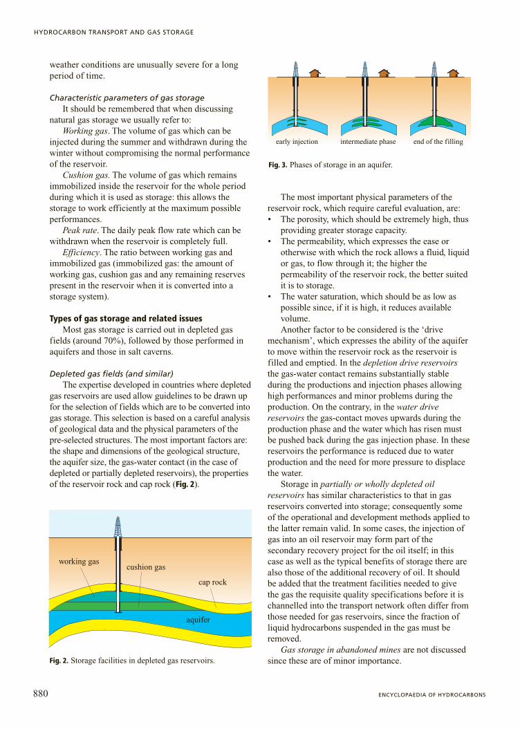
early injection intermediate phase end of the filling
Fig. 3. Phases of storage in an aquifer.

Aquifers As far as gas storage in aquifers is concerned, the
geological structure (trap), which should preferably bean anticline, must first be found. The structure issometimes identified using geological surveys, butgenerally is localized using geophysical systems.
The most important requirement for storagefacilities in aquifers is the seal of the cap rock, whichmust be suitably thick and have low permeabilityvalues, close to zero, as in shaly formations. Thissecond requirement is necessary as during theinjection of gas the hydrostatic pressure is alwaysexceeded.
When the original pressure is exceeded in order toincrease the volume of working gas in storage of thistype (and that in depleted gas reservoirs), care must betaken not to exceed the threshold pressure, in otherwords the pressure above which the gas begins to passthrough the cap rock. The threshold pressure isdetermined in the laboratory by means of tests oncores collected during the drilling phase, andsubsequently with long injection tests performed in thewells (early injection).
To study gas storage in aquifers extrapolationsbased on the data acquired with early injection areemployed. As a result, predictions of the reservoir’sbehaviour during the various phases of storage areinitially uncertain since a production history for thereservoir rock is not available, as is the case fordepleted gas reservoirs.
When storage is initiated in an aquifer, the gasdisplaces the water, advancing more rapidly wherepermeability is higher, and thus leads to the formationof a gas bubble. After a few years, as injectioncontinues, the water in the upper part of the reservoir
is entirely displaced by the gas; at this point thestorage can become operational (Fig. 3).
Salt formations For storage in salt formations, caverns obtained
by dissolving the salt mass in fresh water pumpedthrough one or more wells are used. The salt is thenextracted from the water; when this is not consideredeconomically viable, it is reinjected into anothersuitable geological formation. An understanding ofthe shape of the cavern and the properties of therocks surrounding it are important elements fordetermining the minimum and maximum pressure atwhich the storage can be operated. Generallyspeaking, this type of storage does not have a highworking gas capacity, but do provide considerablepeak rates (Fig. 4).
Comparison between different types of storage andphases of storage
The main characteristics of the different types ofstorage are compared in Fig. 5; for a detailed
881VOLUME I / EXPLORATION, PRODUCTION AND TRANSPORT
UNDERGROUND STORAGE OF NATURAL GAS
0 0
2
4
6
8
2
4
6
8
kmkm
0 1 km
salt dome salt layer
salt
Fig. 4. Storage in salt caverns.
working gas cushion gas
aquifer
cap rock
salt dome
salt
0
2
4
6
8
0 1 km
working gas
cushion gas
efficiency
peak flow rate
high medium low
end of the filling
kmFig. 5. Comparison of the main properties of different types of underground storage.

discussion of geostructural aspects and for reservoirstudies, see Section 7.4.2.
With specific reference to conventional storage(depleted or partially depleted gas reservoirs), Fig. 6shows the different stages of conversion into gasstorage. For the purpose of illustration the case of apartially depleted field is considered, i.e. a fieldcontaining some remaining reserves. Clearly, storagein aquifers or salt caverns contain no primary gas, andall of the gas present in the reservoir has been injected.
Historical development of storage systems The underground storage of natural gas began in
Canada in 1915, and in the United States the followingyear. These two countries were the first to realize theeconomic importance and technical possibility ofstoring natural gas in natural reservoirs.
The use of gas storage spread considerably withthe development and production of gas reservoirs atlarge distances from the areas where the gas was used,and especially with the development of importationfrom one country to another.
The gradual discovery of gas production fields inareas increasingly distant from areas of consumption,an increase in the gas market and the seasonalvariability of natural gas consumption created theright conditions for the development of storageactivities.
One option was to link the sources of supply(national production fields, imports) with gaspipelines whose sizes have been determined as afunction of peak demand. Another option was todetermine the size of the gas pipelines in accordancewith a constant mean supply, supported byappropriately located storage systems aimed atmeeting periodic peaks in consumption. The firstoption entailed larger investments, a failure tooptimize supply with negative economic
consequences, a less efficient use of gas pipelines dueto their excessive size, and a slower response time tomarket fluctuations.
The tendency to store gas in order to modulatesupply began by using tanks located at the surface(gasometers) near towns, and, as production fieldsbecame depleted, by converting these into storagereservoirs. These have extremely high storage capacityand are thus more suited to the growing need of thegas market for storage.
Today there are more than 580 storage fields in theworld, of which 70% are in the United States; theremainder are concentrated almost exclusively inEurope and Russia. Current total availability at worldlevel is calculated to be 286 GSm3 of working gas,with a daily peak rate at maximum capacity of about5.0 GSm3/d.
In the following, the situation for storage sites inEurope, the United States and Canada, and Russia isdescribed.
EuropeMost of Europe’s large storage sites have been
created in depleted or partially depleted gas reservoirs.About 80% of total working gas and daily peak rate isconcentrated in 40 fields out of a total of 103 fields.Currently, Germany is in first place for the availabilityof working gas and daily peak rate, followed by Italy.Tables 1 and 2 show the availability of working gasand daily peak rate for each country and for differenttypes of storage.
United States and CanadaAlso, in the United States and Canada most gas
storage is in depleted or partially depleted reservoirs;in the USA, the greatest concentration is found in theEastern States. At the end of 2004, there were a totalof 456 operational fields. Table 3 shows theavailability of working gas and daily peak rate, alongwith their subdivision by storage typology.
RussiaAlthough the first large storage field became
operational as early as the 1950s, the development ofRussia’s storage system is relatively recent. In the late1980s it was decided to expand the system rapidlywith the development of 8 new storage fields. TodayRussia has more than 60 storage fields, of which 70%are in depleted production reservoirs, accounting forabout 85% of working gas capacity.
Most activities are now aimed at increasing theamount of working gas by raising the storage pressureby up to 40-50% above the original reservoir pressure.Table 4 shows the availability of working gas and dailypeak rate, subdivided also by storage typology.
882 ENCYCLOPAEDIA OF HYDROCARBONS
HYDROCARBON TRANSPORT AND GAS STORAGE
originalfield
produced gas
originalreserve
remainigreserve
remainigreserve
cushiongas
injected gasworking gas
depletedfield
storagefield
Fig. 6. Stages in the conversion of partiallydepleted gas reservoirs into storage fields and characteristic parameters.

Figs. 7 and 8 show the total availability of workinggas and peak rate, as well as their subdivision bystorage typology.
The determination of the size and the developmenta storage field
The determination of the size and the developmenta storage field involves finding a geological structuresuitable for the storage of gas by analyzing itsmineralogical properties and technical and commercialaspects.
Mineralogical properties In the following the analysis is limited to a few
aspects of mineralogical nature, leaving a moredetailed and in-depth discussion to Section 7.4.2. Themain stages of the determination of the size and thedevelopment of a storage reservoir are: a) thegeological study of the structure selected and its cap
883VOLUME I / EXPLORATION, PRODUCTION AND TRANSPORT
UNDERGROUND STORAGE OF NATURAL GAS
Table 1. Availability of working gas in Europe
Country Working gas Peak rate(GSm3) (MSm3/d)
Austria 3.0 35Belgium 0.7 20Denmark 0.8 24France 10.5 214Germany 19.0 445Italy 15.4 282Holland 2.5 144Poland 1.5 52United Kingdom 3.6 138Czech Republic 2.1 42.5Slovak Republic 2.7 33.4Spain 2.1 13Hungary 3.6 46.6
Total 67.5 1,489.5
Table 2. Availability of working gas in Europeby storage typology
Type Working gas Peak rateof storage (GSm3) (MSm3/d)
Depleted fields 42.0 856Aquifers 16.0 208.0Salt caverns 9.5 425.5
Total 67.5 1,489.5
Table 3. Availability of working gas in the USAand Canada by storage typology
Type Working gas Peak rateof storage (GSm3) (MSm3/d)
Depleted fields 111 1,875Aquifers 13 275Salt caverns 5 350
Total 129 2,500
Table 4. Availability of working gas in Russiaby storage typology
Type Working gas Peak rateof storage (GSm3) (MSm3/d)
Depleted fields 76 800Aquifers 13 150Salt caverns 1 50
Total 90 1,000
depleted fields
225
200
175
150
125
100
75
50
25
0
Gm3
aquifers salt caverns
Fig. 7. Total availability of working gassubdivided by storage typology.
depleted fields aquifers salt caverns
3,5003,250
3,750
3,0002,7502,5002,2502,0001,7501,5001,2501,000
750500250
0
Mm3/d
Fig. 8. Total peak rate subdivided by storagetypology.

rock; b) the study of its behaviour during theproduction phase, for depleted or partially depletedgas reservoirs (conventional storage); c) the dynamicsimulation of the behaviour of the reservoir during theinjection and production phases, using mathematicalmodels developed for this purpose; d ) thedetermination of performance when the reservoir isfilled to the original pressure and to a pressure abovethe original one, by assuming different dynamicpressure values at the wellhead; and e) thedetermination of reservoir performance as a functionof the number and type of wells (vertical or horizontalwells), and the type of completion (completion withgravel pack, large diameter tubing, etc.).
For depleted or partially depleted gas reservoirs,the studies mentioned in the first two points havealready been carried out and updated during theproductive life of the reservoir. Specifically, theanalysis of dynamic behaviour undertaken during theprimary production phase allows the identification ofthe characteristic parameters of the reservoir-aquifersystem (drive mechanism by simple expansion,moderate water-drive, strong water-drive); these arefundamental for determining the dimensions in termsof the capacity and productivity of the future storage.
As far as the dynamic simulations are concernedmathematical models are used; these are generallythree-dimensional and are able to simulate productionhistory and predict the future performance of thereservoir during the storage phase. These simulationsallow the determination of the possible performance aswell as the other parameters characterizing the storage(working gas, peak rate of delivery/injection, cushiongas), by assuming different values for reservoirpressure and wellhead pressure (Figs. 9 and 10).
Technical and commercial aspects As mentioned above, the determination of the size
and the development of a geological structure to beused for storage depends on the geometry of thereservoir and its petrophysical properties, but also onother parameters which are established during theplanning phase, and which take account of marketrequirements (the need for working gas and daily peakrate), and the restrictions imposed by the transportnetwork.
Economic aspects must also be studied and tariffsfor the services offered set on the basis of currentregulations. Only once the analyses described abovehave been carried out, can the size of the facilities bedetermined in an optimal way, and the number of wellsbe established with a reasonable margin of certaintythat the volume of gas stored and delivered will beused, and thus that the services on offer arecompetitive.
Services and ways of using storage systemsThe traditional services offered by storage
reservoirs are production services, seasonal controlservices and strategic reserves services.
In recent years, many European countries,including Italy, have followed the example of theexisting practice in the USA and the United Kingdom,which attempts to increase the flexibility of storagesystems by providing a broad range of so-called‘special’ services, with undisputed benefits both forthe operators of gas storage and for gas salescompanies.
In the following, the different types of service onoffer are briefly analysed.
884 ENCYCLOPAEDIA OF HYDROCARBONS
HYDROCARBON TRANSPORT AND GAS STORAGE
1st month
2nd month
3rd month
4th month5th month
0 100 125 1400
100
6th month
FTHP=45
FTHP=60
FTHP=75
peak
rat
e in
crea
se (
%)
working gas increase (%)
Fig. 9. Variations in performance as wellheadpressure varies.
peak
rat
e in
crea
se (
%)
150
100
00
working gas increase (%)
100 130
1st month
1st month
2nd month
2nd month
3rd month
3rd month4th month
4th month5th month
5th month 6th month6th month
Pmax = PorPmax = 115% Por
Fig. 10. Example of improved performance as the maximum working pressure of the reservoir is varied.
Production servicesFor technical and financial reasons, production
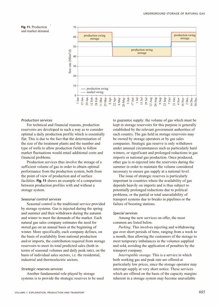
reservoirs are developed in such a way as to consideroptimal a daily production profile which is essentiallyflat. This is due to the fact that the determination ofthe size of the treatment plants and the number andtype of wells to allow production fields to followmarket fluctuations would entail additional costs andfinancial problems.
Production services thus involve the storage of asufficient volume of gas in order to obtain optimalperformance from the production system, both fromthe point of view of production and of surfacefacilities. Fig. 11 shows an example of a comparisonbetween production profiles with and without astorage system.
Seasonal control services Seasonal control is the traditional service provided
by storage systems. Gas is injected during the springand summer and then withdrawn during the autumnand winter to meet the demands of the market. Eachnatural gas sales company estimates the need forstored gas on an annual basis at the beginning ofwinter. More specifically, each company defines, onthe basis of availability from national productionand/or imports, the contribution required from storagereservoirs to meet its total predicted sales (both interms of seasonal volumes and daily peak rate), on thebasis of individual sales sectors, i.e. the residential,industrial and thermoelectric sectors.
Strategic reserves servicesAnother fundamental role played by storage
systems is to provide the strategic reserves to be used
to guarantee supply: the volume of gas which must bekept in storage reservoirs for this purpose is generallyestablished by the relevant government authorities ofeach country. The gas held in storage reservoirs maybe owned by storage operators or by gas salescompanies. Strategic gas reserve is only withdrawnunder unusual circumstances such as particularly hardwinters, or significant and prolonged reductions in gasimports or national gas production. Once produced,other gas is re-injected into the reservoirs during thesummer in order to maintain the volume considerednecessary to ensure gas supply at a national level.
The issue of strategic reserves is particularlyimportant in countries where the availability of gasdepends heavily on imports and is thus subject topotentially prolonged reductions due to politicalproblems, or the partial or total unavailability oftransport systems due to breaks in pipelines or thefailure of boosting stations.
Special servicesAmong the new services on offer, the most
common are listed below.Parking. This involves injecting and withdrawing
gas over short periods of time, ranging from a week toa month, thus allowing the customers of the storage tomeet temporary imbalances in the volumes suppliedand sold, avoiding the application of penalties by thetransport company.
Interruptible storage. This is a service in whichboth working gas and peak rate are offered atparticularly low prices, since the storage operator mayinterrupt supply at very short notice. These serviceswhich are offered on the basis of the capacity marginsinherent in a storage system may become unavailable
885VOLUME I / EXPLORATION, PRODUCTION AND TRANSPORT
UNDERGROUND STORAGE OF NATURAL GAS
production swingstorage
production swingstorage
production swingstorage
70
60
50
40
30
20
10
0
1 Ja
n
15 J
an
29 J
an
12 F
eb
28 F
eb
11 M
ar
25 M
ar
8 A
pr
22 A
pr
6 M
ay
20 M
ay
3 Ju
n
17 J
un
1 Ju
l
15 J
ul
29 J
ul
12 A
ug
26 A
ug
9 S
ep
23 S
ep
7 O
ct
21 O
ct
4 N
ov
18 N
ov
2 D
ec
16 D
ec
30 D
ec
production swingmarket swing
flow
rat
e (M
Sm
3 /d)
Fig. 11. Production and market demand.

in the event of unplanned maintenance work, plantfailures, the closure of wells, etc.
Capacity trading. This involves the buying andselling of volumes of gas by customers, who, formarket reasons (variations in gas demand or supply),have booked smaller or larger volumes than necessaryfrom storage systems. This is common practice inalmost all countries, and allows an optimal use ofstorage capacity and the avoidance of additionalexpenditure.
Figs. 12 and 13 show the variations in someparameters (gas in the reservoir, working gas and peakrate) during the injection and later production cycles.
The gas market and need for stored gasIn the coming decades, an increase in gas
consumption in most countries is predicted, mainly asa result of growing consumption in the thermoelectricsector. Annual consumption is predicted to increase onaverage by 2.4% over the next three decades, goingfrom 2,527 GSm3 in the year 2000 to about
5,000 GSm3 in 2030. The contribution made by gas toprimary energy consumption will increase from 23%in the year 2000 to 28% in 2030.
The forecast growth of the gas market willnecessarily lead to an increase in the number ofstructures to be used for storage as well as an increasein the storage capacity. The increase in storagecapacity in Europe and the United States betweentoday and 2010 (no reliable data are available forRussia and Eastern countries) will be in the order of57 GSm3 for working gas, and 1,100 millions of Sm3/dfor peak rate (35% in Europe). The total availability ofstorage systems in 2010, without considering possibleincreases in Russia and Eastern countries, should thusbe about 350 GSm3 of working gas and about6 GSm3/d for peak rate.
Criteria used to determine the need for storagesystems
Before outlining the criteria used to determine theneed for gas, it is worth noting some of the parameterscharacterizing the gas market.
Degree days. These express the difference indegrees Celsius (or Fahrenheit) between a referencetemperature of 18°C (64°F), at which consumption forresidential heating purposes is considered to be zero,and the mean daily temperature; in other words the°C/d represent the complement to the value of 18°C(64°F) given by the forecast and actual temperature.For example, if during October the mean value ofdegree days is 5°C/d, the mean temperature to beconsidered for the month is 13°C. Fig. 14 shows anexample of a temperature profile (forecast and actual)in °C/d; by summing the degree days for a month or aseason it is possible to obtain estimates of the demandfor gas for heating purposes.
Specific consumption. This is the volume of gasused for heating per 1°C/d variation with respect to thereference temperature of 18°C.
Flexibility. This parameter is linked to the ratio ofthe minimum number of days required to deliver agiven volume of gas to the number of days in a year.If, for example, this ratio is 0.9, the volume inquestion can be supplied in 328 days. Flexibilityincreases as the value of the ratio decreases: thismeans that the greater the flexibility, the larger thedaily volume of gas which can be used during thewinter.
As has already been stressed, the regulatoryseasonal function played by storage systems becamenecessary to meet market demand. Here, the mainparameters used to determine the need for stored gasare listed; these parameters are the annual sales andthe relevant monthly and daily profiles for theindustrial, thermoelectric, basic residential and
886 ENCYCLOPAEDIA OF HYDROCARBONS
HYDROCARBON TRANSPORT AND GAS STORAGE
flow
rat
e (S
m3 /d
)
flowing phase
injection phase
produced/injected gas (MSm3)
peak flow rateinjection peak rate
Fig. 12. Peak flow rate for injection and production during a storage cycle.
gas
in p
lace
(M
m3 )
year 1
remaining reserve
cushion gas
working gas
injection production staticpressure
year 2
Fig. 13. Examples of storage cycles.

residential heating sectors, as well as the monthly anddaily profile of volumes supplied over the course ofthe year.
Annual sales and monthly and daily profilesThe need of each individual sales company for
stored gas is estimated on the basis of the differentcomponents of the market (thermoelectric, industrial,residential domestic and residential heating sectors).The residential heating sector, in particular, presentsthe greatest degree of forecasting uncertainty, since itdepends on actual climate conditions. For planningpurposes, requirements are estimated both in terms ofthe volume of gas needed and the daily peak rate,taking into consideration both a ‘normal’ temperatureprofile based on a 30-50 year period (variabledepending on the country) and a particularly coldtrend (occurrence probability from 1:20 to 1:50 years).
The method used to determine the residential salesprofile involves calculating the specific consumptionfor heating purposes in millions of Sm3/(°C/d). Thiscan be obtained from the ratio of the volume of gassold during the previous winter to the total value ofdegree days in the geographical areas where themarket of the gas company is located. This value isthen ‘normalized’ by taking account of annual meandegree days for the time period considered.
Once the specific consumption has beendetermined, the sales profile for residential heating isthen defined on the basis of the mean monthlytemperatures (for monthly volumes), or three dayaverages (for daily volumes), taking into considerationany variations in the number of customers served.
The sales profile for industrial purposes isgenerally flat, and takes into consideration any periodsof inactivity predicted by the various users; the
thermoelectric profile may be influenced significantly,and in a different manner from country to country, bythe more or less intensive use of air-conditioningduring the summer.
The total consumption thus obtained allows thestorage requirements to be defined on a mean monthlyand daily basis both in the case of a normal thermaltrend and in the case of cold winters (Fig. 15).
Annual supply and monthly and daily profileThe supply profile over the course of the year
depends on the flexibility of national productionfields, and import contracts; these flexibilities are usedto maximize winter supply, thus reducing the need forstored gas to meet market demands.
887VOLUME I / EXPLORATION, PRODUCTION AND TRANSPORT
UNDERGROUND STORAGE OF NATURAL GAS
30
monthly average degree days
28
26
24
22
degr
ee d
ays
(°C
/d) 20
18
16
14
12
10
8
6
4
2
0Oct Nov Dec Jan Feb Mar Apr May
normal degree days(three days value)
actual temperaturenormal temperatureactual averagenormal average
Fig. 14. Example of a meantemperature profile in°C/d (forecast and actual)for a European country.
500
450400350
300
250
200
150
100
50
0November
import swing
gas productionin cold winter
gas productionin normal winter
domesticproduction
gas import
hour demand withexceptional cold
daily demand withexceptional cold
December January February March
flow
rat
e (M
Sm
3 /d)
Fig. 15. Typical pattern for daily winter demandin a European country.

On the basis of sales and supply profiles, eachcompany determines the volumes of stored gas to bereserved.
In turn, the storage companies check thecompatibility of these requests with the characteristicsof their own storage system, and any restrictionsimposed by surface facilities and/or the transportnetwork.
In the course of the season a monthly check ismade on any deviation from the programme as a resultof the actual profile of both sales and availability, andwhere necessary, the forecast injection/supply strategyis adjusted to obtain optimal performance from thestorage system.
Alternatives solutions to reduce the need for stored gas
In most countries with a mature gas market, thevarious operators (gas sales companies, transportcompanies, etc.) often adopt a series of alternativesolutions to reduce the need for stored gas.Alternatives to storage are taken into consideration ifthey are economically advantageous, and are essentialwhen the availability of stored gas has reached itslimits, or is insufficient due to a lack of suitablegeological structures. Table 5 highlights the impact ofthese various alternatives on the need for working gasand peak rate.
Development costs and management of storage fields
InvestmentsThe investment cost for the development of a
new storage field depends on the type of storageand, in the case of identical types of storage, on itscapacity, which may or may not permit economiesof scale.
Investment costs for a storage project can besubdivided into: a) exploration costs (unnecessarywhere partially depleted or depleted gas/oilreservoirs are used); b) drilling costs which arerelated to the number and depth of the storagewells; c) costs of the cushion gas volume; and d ) costs of surface facilities, related to the size ofthe treatment and compression plants. In thiscontext we should remember that similar surfacefacilities are generally used for conventional andsemiconventional storage.
The overall cost of a single storage facility dependson: a) the size of the surface facilities necessary fortreatment and compression of the gas; b) the numberand depth of the wells; c) the number of caverns/wellsin the case of salt cavities; and d ) the volume ofcushion gas.
Operating costsThe cost of managing gas storage can be divided
into fixed and variable costs. Fixed costs are thoserelated to the workforce, insurance, maintenance work,etc. Variable costs are the costs of the fuel and/orelectrical energy required to power the compressors,consumer goods, etc.
Economic considerations on the development of storage in depleted gas reservoirs
For this type of storage exploration costs aregenerally unnecessary, since the reservoir isalready well-known from the point of view of boththe geology and productive behaviour. On rareoccasions additional wells may be necessary inorder to locate the boundaries of the reservoirmore accurately; more frequently, new wells of adifferent type from existing wells may have to bedrilled (horizontal wells, wells with gravel pack,i.e. wells with calibrated sand filters or wells withlarge diameter tubing) to allow high daily flowrates and reduce the time required toinject/withdraw gas.
Most existing surface facilities (gas dehydrationplants, compressors, pipelines, instrumentation,control room, etc.) and wells can also be used forstorage facilities, even though with somemodifications.
The volume of gas to be immobilized as cushiongas depends on the size of the reservoir and the drivemechanism (the volume of gas is smaller forreservoirs which produce by simple expansion thanfor those which produce by water-drive). The impactof cushion gas on total investments depends on howmuch of this is still present in the reservoir when it isconverted into a storage site, and on how much mustbe purchased at market prices and injected into thereservoir.
888 ENCYCLOPAEDIA OF HYDROCARBONS
HYDROCARBON TRANSPORT AND GAS STORAGE
Table 5. Possible alternative to reducestorage demand
Contribution Contributionto the reduction to the reduction
of working gas of the peak rate
Flexibility High Lowof the demand
Interruptible High Highmarket
Flexibility Highof the LNG plants
Line-pack Medium
SPOT demand High Lowcontracts

Economic considerations on the development of gas storage in aquifers
The search for these geological structures requiresconsiderable exploration expenditure to identify thosesuitable for storage. Once the structure has beenidentified, it is necessary to drill all of thedevelopment wells and build the treatment andcompression plant, without the possibility of usingexisting facilities.
The volume of gas to be immobilized as cushiongas is large, since the front of the aquifer must be keptat a distance from the productive zone; the impact ontotal investments is significant, since all of the gasused for this purpose must be bought on the openmarket and injected into the reservoir.
Economic considerations on the development of gas storage in salt caverns
These types of storage use underground cavernswhich are sometimes created by the exploitation of saltformations to extract rock salt; in other cases they arecreated specifically for storage. It is clear that in theformer case investment costs are limited to those forwells and the treatment and compression plant,whereas in the latter case exploration costs and thecost of artificially creating the cavity must also betaken into consideration.
The volume of gas used as cushion gas is relativelymodest, and is conditioned only by the minimum
pressure which we wish to maintain at the end of theflowing cycle.
Estimates of investment costsOn the basis of the considerations outlined above,
rough estimates for typical storage are as follows:storage in depleted reservoirs: 170-200 millions ofeuro; storage in aquifers: 250-300 millions of euro;and storage in salt caverns: 290-340 millions of euro.
It should be noted that it has been assumed that thecushion gas consists of gas acquired on the market andinjected into the reservoir. Table 6 shows the mainparameters characterizing ‘typical’ European storage,while Table 7 shows the mean impact of individualitems of expenditure.
Methods of increasing the storage capacityThe performance of gas storage which is already
operational can be increased with smaller investmentsthan those required for the development of a new fieldby carrying out a series of interventions, as outlinedbelow.
Increase of original reservoir pressure (depleted gas/oil reservoirs)
The maximum pressure which can be reached iscalculated by reservoir studies aiming to define thegeometry and extent of the reservoir rock, and withlaboratory analyses of cores collected from the top of
889VOLUME I / EXPLORATION, PRODUCTION AND TRANSPORT
UNDERGROUND STORAGE OF NATURAL GAS
Table 6. Main parameters in a typical European storage
Parameters Depleted reservoirs Aquifers Salt caverns
Total volume (MSm3) 1,665 1,000 430
Working gas (MSm3) 1,000 500 300
Efficiency (%) 60 50 70
Depth (m) 1,300 900 1,260
Storage pressure (bar) 135 90 150
Peak rate (MSm3/d) 12 6 18
Number of wells 25 20 10
Working gas/well (MSm3) 40 25 30
Peak rate/number of wells (MSm3/d) 0.48 0.24 1.8
Table 7. Mean impact of the main items of investment costs
Class of investment Depleted reservoirs (%) Aquifers (%) Salt caverns (%)
Surface plants 30 25 40
Wells 25 15 35
Cushion gas 45 60 25
the reservoir. These analyses aim to characterize thecap rock and determine its petrophysical andgeomechanical properties (threshold pressure,permeability, porosity, etc.).
In addition, the condition of existing wells must beevaluated, and the presence of faults and the fracturegradient of the cap rock must be investigated.
On the basis of these investigations the maximumworking pressure can be calculated, thus avoiding anypossible gas leaks caused by exceeding the thresholdpressure and any potential mechanical damage to thecap rock caused by fracturing.
The maximum injection pressure is limited to thelowest of the following values: the pressure valuecalculated as the sum of the hydrostatic pressure onthe cap rock plus the threshold pressure, the value atwhich the integrity of the well may be compromisedand the fracture value of the cap rock.
Increasing the number of wellsThis is now common practice among storage
operators, and allows significant increases to beobtained, especially in the peak rate of the storage. Themaximum number of wells depends on the type andsize of the reservoir, and must be defined so as toavoid interference problems between wells andreductions in the reservoir performance.
Upgrading treatment and compression facilitiesThe work required is basically restricted to the
installation of additional treatment columns and one ormore compression modules able to operate at theactual capacity of the reservoir. If necessary, the flowlines must be expanded in order to minimize pressurelosses.
Operating systems to manage and controlproduction
The technology currently used to managetechnical, managerial and commercial problems instorage fields make use of computer systems whichallow control of production and processing,optimization of production and injection, andmanagement of commercial issues.
Control of production and processingThe computer systems used are management and
remote control systems which allow: constantmonitoring of the functional conditions of plants andfield appliances, thereby guaranteeing the safety ofappliances, people and the environment; remotemanagement of storage facilities which are partiallymanned or unmanned, thus significantly reducingexpenditure and control of production in a moreeffective and dynamic way; and centralization of
production management and planning to improveresponse times to the numerous demands of themarket.
The fundamental issue which must be tackled incontrolling production and processing is the definitionof the optimal automation level for the plants.
A simplistic approach would be to automate allappliances. However, aside from obvious economicconsiderations, it has been demonstrated that evenfrom a technical point of view this may lead to areduction in the overall availability of the plant and anincrease rather than decrease in the number ofemployees.
This problem can be tackled by defining the plant’savailability as:
MTBFA�1111113
MTBF�MTTR
where A is the percentage value of availability, whichexpresses the ability of a system to perform the taskfor which it is designed; MTBF (Mean Time BetweenFailures) is the temporal value which expresses themean interval between two subsequent system failures,assuming that the cause of the first failure has beeneliminated; MTTR (Mean Time To Repair) is thetemporal value which expresses the mean timerequired to repair a system failure.
Appropriate formulas allow the value of theavailability of complex plants to be calculated bycombining the values for MTBF and MTTR ofindividual components. The specific treatment of thisargument lies outside the scope of this chapter,however it is important to highlight that, while thevalue of the MTBF is an intrinsic characteristic of theproduct, the value of the MTTR to be used in theformula is made up of a number of contributions.Some of these contributions arise from the intrinsiccharacteristics of the system and are related to theorganizational structure of the user into which,computer systems and remote control are added inorder to improve the efficiency and economy of thesystem, also achieved by the fact that the plants can beunmanned.
In a manned plant, it is tolerable for a minor failureto interrupt the functioning of part of the plant, since itis reasonable to suppose that timely maintenance workwill allow production to resume after a very shorttime, thus contributing only in a limited way to adecrease in availability.
For unmanned plants the situation is different: inthis case, the same type of failure, given the timerequired to intervene (we can assume that maintenanceworkers must travel to the site from elsewhere), maylead to a long period of unavailability. This problemcan be resolved by the modularization and redundancy
890 ENCYCLOPAEDIA OF HYDROCARBONS
HYDROCARBON TRANSPORT AND GAS STORAGE

of the plant itself; these properties can be exploited bythe automated system to attain the required levels ofavailability.
On the basis of these considerations, it is obviousthat during the design of computerized managementsystems for unmanned or partially manned storagestations, adjusting the layout of the plants isparticularly important.
When choosing and designing monitoring systemsthe following criteria must be taken into account: themodularity of the system’s hardware and softwarearchitecture, the integration with other existingsystems in the plant, flexibility in adapting to varyingneeds and types of plant, the expansibility of hardwareand software in the field, advanced functions and theindependence from the hardware platform.
The need for flexibility in meeting the variousrequirements which may emerge over the course of theproductive life due to a different use of the storagefields or the modification of plants make it advisable tochoose standard and open system technologies, basedon a distributed database to which all SCADA (SystemControl And Data Acquisition) functions refer.
Hardware and remote control architecture. Thehardware architecture is designed and built usingcomputerized systems operating on heterogeneousplatforms and on three functional levels. The primaryelement of this architecture is the process controlsystem, typically of the DCS (Distributed ControlSystem) type. This consists of modules to controlprocessing and plant supervision units, able tointerface with the plant remote control systems(Fig. 16).
At a higher functional level, a SCADA is installedwhich, using appropriate links and communicationsprotocols, exchanges data and exploits the automationlogic of the station’s DCS, thus allowing the storagefacilities to be remote controlled.
The architecture is completed with the installationof host computers, linked to the SCADA, which areable to implement applications aimed at optimizingproduction processes and carrying out productionaccountancy.
Software architecture. Implementing theaforementioned hardware architecture allows thedevelopment of software which, by exploiting theprocess automation, minimizes the controls andinterventions which the operator is required to makeon individual parts of the plant. These applications canmanage all types of regulation and control, and anymalfunctions detectable in the field by restartingand/or shutting down the production process.
Production is controlled and regulated at thestation by implementing a hierarchical softwarearchitecture at the DCS level, operating on three levelsof functions which interact with one another; these arethe implementation of:• A first level of management logic for individual
appliances such as pumps, engines, etc., in linewith internal management and safety practice;implementation of process control loops.
• A second level of automated managementfunctions for complex parts of the plant such as awell/separator unit or a dehydration column.
• A third level of functions able to manageautomatically entire parts of the plant such as thewells, the dehydration columns, etc.Furthermore, process control scans will also be
implemented at predetermined time intervals.The storage facilities are remote controlled by
linking the SCADA (usually centralized in a suitablelocation) to the station DCS, with special care devotedto choosing the type of connection and thecommunications protocol. Where necessary, hardwareand software redundancy must be installed in bothsystems and in the relevant lines of communication, inorder to ensure a high degree of safety from the pointof view of operational continuity. On the station DCSa fourth level of functions is implemented allowing theplants to be remote controlled during the withdrawaland storage phases.
The type, and above all the number, of variables intransmission is directly proportional to the degree ofautomation obtained on the station control system.Host computers, on which production control andmanagement functions have been implemented, arealso connected to the SCADA. These may include thebalance of gas withdrawn and injected, and itsdistribution over the wells, control of the productionparameters of the wells, display of production andstorage trends, and integration with applicationsdeveloped on centralized information systems for thedistribution of data to management and technical units.
Systems architecture. The systems architectureinvolves implementing four different levels offunctions allowing a high degree of automation of theplant to be achieved, especially as concerns theproduction process (see again Fig. 16).
891VOLUME I / EXPLORATION, PRODUCTION AND TRANSPORT
UNDERGROUND STORAGE OF NATURAL GAS
I
II
III
IV level IV: production management
level III: overall plant management
level II: plant unit management
level I: device management
Fig. 16. Logical scheme for the primary control element.

The activities carried out automatically by thesystem, and at the request of the operator, are asfollows: a) automatic management of the productionphase and maintenance of the production levels set bythe operator; b) automatic management of the storagephase; c) control of the correct functioning of the plantduring the withdrawal and storage phases, and switchto the shut-down phase in the event of malfunction;and d ) control and maintenance of the requisite safetylevels during the production and storage phases.
The district control room operator supervises andmanages the plant, sending commands which act onlevels 3 and 4 of the DCS software architecture. Theseallow the required production level to be set, and theautomatic management of those plant units whichpresent anomalies, or which are undergoingmaintenance work to be disabled. It is the operator’stask to check the station DCS diagnostics informationand the condition of the data communication lineswith the district SCADA. Using this procedure tomanage storage fields is simple, dynamic and allowsrisk and the impact of human error to be reduced to aminimum.
Production management. Production managementat storage fields is thus entirely automated, and isimplemented from the district control room by sendinga single command indicating the required flow rate.This command is finalized on the station DCS, whichmanages the wells and facilities in such a way as toguarantee the required level of production. The systemautomatically checks that all production units arefunctioning correctly and that safety standards aremaintained; it also automatically carries out actionsaimed at maintaining the required level of productionand, in the event of malfunction, shuts down the plants.
As far as the control and management ofproduction are concerned, algorithms are installed onthe DCS, at the fourth level of the applicationssoftware, which reproduce the curve characterizing thereservoir’s deliverability and injectivity. Using thesealgorithms allows the following operations to becarried out automatically: a) the adjustment of themaximum flow rate of the wells depending onreservoir cumulative production; b) the managementof the production of wells as a function of flow rateand according to priorities and criteria established as afunction of their location and production properties; c) the control of the pressure differential between thereservoir and the tubing applicable on each well; andd ) the adjustment of the field’s regime as a function ofreservoir cumulative production.
Optimization of production and injectionThe optimization of the production and injection
allows: the exploitation of the different physical
properties of each field in an optimal way, taking intoconsideration surface constraints, so as to obtainsignificantly improved performance without alteringthe volumes moving through the storage system; theoptimal use of each level of the reservoir as a functionof its petrophysical properties and drive mechanisms;and the determination the daily flow rate of each wellat any time taking account of its location, the type ofcompletion, the production and injection carried out.
In this context, it is worth remembering thatstorage fields can be divided into two majorcategories: base storage fields and peak storage fields.Base storage fields are used throughout the winter fora number of days ranging from a minimum of 90 to amaximum of 140; these fields contain a large volumeof working gas (from about 0.5 to 3.5 GSm3) andexhibit a slow decrease in daily peak rate duringproduction (Fig. 17). The ratio of working gas to dailypeak rate is about 50-60 millions of Sm3/millions ofSm3/d. Most storage in depleted gas reservoirs andsome in aquifers belong to this category.
Peak storage fields are used only for brief periodsover the winter to meet peaks in daily demand; thenumber of days of use may range from a minimum of15-20 to a maximum of 40-50, depending on theirstorage capacity. Working gas is usually less than 0.5GSm3, with a ratio of working gas to daily peak rate ofabout 30-40 millions of Sm3/millions of Sm3/d. Thedecrease in daily peak rate during production isconsiderable (Fig. 18). Most storage fields in saltcaverns, and some in depleted gas reservoirs andaquifers, belong to this category.
If the annual, monthly and daily requirements ofthe storage system’s customers are known, the amountof working gas and the peak rate needed from thestorage system can be calculated. Each customercommunicates their own requirements to one or morestorage companies; on the basis of total requirements,each storage company defines the volume which
892 ENCYCLOPAEDIA OF HYDROCARBONS
HYDROCARBON TRANSPORT AND GAS STORAGE
peak flow rate
cumulative production (Sm3/cycle)
flow
rat
e (M
Sm
3 /d)
Fig. 17. Qualitative profile of peak flow rate as a function of cumulative production in a base storage field.
individual storage fields must deliver and inject each month.
Total demand is distributed over the differentstorage fields making up the system by optimizing theproduction properties of each of these (base storagefields or peak storage fields), and taking intoconsideration any constraints on compression andtreatment plants and the transport system. Using andmanaging storage systems in this way allows the bestwithdrawal/injection profile to be identified for eachfield, with the aim of ensuring that the systemperforms in an optimal way.
The basic data used for optimization are thedeliverability/injectivity curves for all of the fieldsconstituting the storage system, and the load curvewhich the system must satisfy (the volume of gaswhich the various fields being optimized must supply).
Specifically, the deliverability/injectivity curvesare obtained by means of the following threeparameters: daily rate as a function of cumulativeproduction/cumulative injection (Qd); cumulativeproduction/cumulative injection as a function of time(S); and pressure as a function of cumulativeproduction/cumulative injection (p).
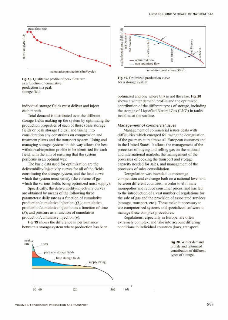
Fig. 19 shows the difference in performancebetween a storage system where production has been
optimized and one where this is not the case. Fig. 20shows a winter demand profile and the optimizedcontribution of the different types of storage, includingthe storage of Liquefied Natural Gas (LNG) in tanksinstalled at the surface.
Management of commercial issuesManagement of commercial issues deals with
difficulties which emerged following the deregulationof the gas market in almost all European countries andin the United States. It allows the management of theprocesses of buying and selling gas on the nationaland international markets, the management of theprocesses of booking the transport and storagecapacity needed for sales, and management of theprocesses of sales consolidation.
Deregulation was intended to encouragecompetition and exchange both on a national level andbetween different countries, in order to eliminatemonopolies and reduce consumer prices, and has ledto the introduction of a vast number of regulations forthe sale of gas and the provision of associated services(storage, transport, etc.). These make it necessary touse computerized systems and specialized software tomanage these complex procedures.
Regulations, especially in Europe, are oftenextremely complex, and take into account differingconditions in individual countries (laws, transport
893VOLUME I / EXPLORATION, PRODUCTION AND TRANSPORT
UNDERGROUND STORAGE OF NATURAL GAS
peak flow rate
cumulative production (Sm3/cycle)
flow
rat
e (M
Sm
3 /d)
Fig. 18. Qualitative profile of peak flow rate as a function of cumulative production in a peak storage field.
end
Oct
ober
end
Nov
embe
r
end
Dec
embe
r
end
Janu
ary
end
Febr
uary
end
Mar
ch
cumulative production (GSm3)
avai
labl
e pe
ak r
ate
(MS
m3 /d
)
optimized flownon optimized flow
Fig. 19. Optimized production curve for a storage system.
peakrate LNG
peak rate storage fields
base storage fieldssupply swing
30 60 120 365 t (d)
Fig. 20. Winter demandprofile and optimizedcontribution of differenttypes of storage.

regulations, storage regulations, Authoritydeliberations, etc.). However, EU directives, currentlyin the process of definition, aim to harmonize theseprocedures and to introduce criteria of reciprocity inorder to simplify and render more transparent theexchanges between different countries.
Outline of legislation on storage fieldsIn most European countries, the use of geological
structures for storage is granted in the form of alicence issued by central State agencies. Somecountries, including the United Kingdom, are anexception; here no licence is needed, only anauthorization from the relevant agency. In the UnitedKingdom, licences are obligatory only when one ormore levels of a reservoir which is still in productionare to be used for storage. Also in the USA thegeological structures used for storage are granted by alicense issued by the Department of Natural Resourcesof each Federal State.
The regulations governing the use of licenses andauthorizations are issued by central State agencies (theministry, the national mineral office, etc.) in the formof laws, decrees and exemplary rulings. In manycountries the authority to issue evaluations ofenvironmental impact and construction licenses isdelegated to Regions (Districts) or local governments.The task of drawing up criteria for the determinationof allowed revenues and price structures and anycriteria for prioritizing the assignation of availablecapacity, on the other hand, is delegated to regulatorybodies such as: OFGEM (Office of Gas and ElectricityMarkets, United Kingdom), CRE (Commission deRégulation de l’Energie, France), AEEG (Autorità perl’Energia Elettrica e il Gas, Italy), and FERC (FederalEnergy Regulatory Commission, USA).
The duration of licences ranges from 5 to 30 years,with the option of one or more extensions ofpredetermined length. The companies holding storagelicences may be gas transport companies, gasdistribution companies, or storage companies. Inaddition to ensuring sufficient finance for thedevelopment and management of this activity, theymust have the requisite know-how for theimplementation of the operations.
Regulation of services offered by storage systemsThe fees for storage services may be established by
negotiation, regulation, or a mixture of the two. Incountries with several storage operators, none ofwhich dominates the market, and where availablecapacity is sufficient to meet market requirements,fees are usually established by negotiation betweenstorage operators and customers. In these countries,services can be offered on a competitive basis without
compromising the range of services on offer, thusencouraging operators to become more efficient andtherefore to contain prices. In Europe, negotiation isapplied in the United Kingdom; in the USA servicesare now mainly negotiated.
In countries where the total availability of gasstorage is insufficient or limited with respect to marketrequirements, or where there are few operators, ofwhich one is in a dominant position (and where thereis thus no possibility of genuine competition),regulation is needed to avoid distorting the market anddiscrimination between users. Such regulationssystems allow storage companies a rate of return onthe expenditure incurred by establishing an adequateprofit margin.
In both cases (negotiated or regulated systems),remuneration must also take account of possibletechnical risk (gas leaks, decrease in performance,etc.), and risks linked to the margin of uncertaintyinherent in forecasts of the use of stored gas over themedium to long term.
Criteria used to determine pricesIn the case of a regulated system, fees are
established on a cost reflective basis throughcalculation of the allowed revenue by applying a rateof return to investments and operating costs (fixed bythe energy sector regulatory body in Europe and by theFERC in the USA), while guaranteeing an adequateprofit margin to encourage this industry. The feestructure may cover the combined provision ofworking gas and daily peak rate, or the separateprovision of working gas, daily peak rate and gasinjected into or removed from the storage.
When the service is negotiated, the rate of return isnot set by any controlling body, although the logicbehind the calculation of profits is basically identical;in this case it is clear that it is the market which mainlydetermines profits and prices.
The methodology used to establish fees assumesthat profits must be distributed over the services on offer. If separate services are offered, then the proportion of profits (associated with therelevant part of the facilities) attributed to working gasand daily peak rate must be established. When a package of services is offered, total profits aredistributed over working gas and daily peak rate in a given ratio depending on the type of storage (m3 working gas / m3/d rate).
In the case of a regulated service, the fee structureshould: a) facilitate competition and avoid cross-subsidiarity between stored gas users; b) encourage anefficient use of storage; c) ensure an adequatedevelopment of investments if these are necessary; andd ) be stable, clear, transparent and reviewed at
894 ENCYCLOPAEDIA OF HYDROCARBONS
HYDROCARBON TRANSPORT AND GAS STORAGE
predetermined intervals in order to take into accountpossible variations in costs and storage parameters,and possible increases in efficiency. If necessaryinternational benchmarking, or reference to theservices offered by other countries may be consideredin order to support the tariffs determined.
For a negotiated service, the fee structure must: a) be non-discriminatory; b) avoid cross-subsidiaritybetween stored gas users; c) encourage effectivecompetition in the use of storage services; and d ) allow an adequate development of investmentsdepending on the need for gas from storage fields.
The relevant authorities (ministries, energyauthorities, etc.) may re-examine the need forregulation or negotiation, depending on changesresulting from the greater offer of storage services.
Compression and treatment of gasVolumes of gas are moved between the transport
system and the storage through the gas storage station.The station contains all the machinery and plantsneeded to inject natural gas from the transport systeminto the reservoirs and to deliver gas from the reservoirto the transport network.
The sizes of all appliances contained inside thestations are determined so as to allow a completestorage cycle, on the basis of the maximumperformance obtainable from the reservoir. In thiscontext, it should be remembered that each cycle iscomprised of an injection phase (storage) and adelivery phase (production) in which the volumesstored during the previous phase are returned to thesystem from which they were withdrawn. In orderto define the sizes of the appliances, the in/outvolumes of a storage cycle (working gas) aredetermined by means of the reservoir studies basedon the physical properties of the field andpetrophysical properties of the reservoir rock,using mathematical models able to simulate thevarious phases of storage.
The main processes to which the gas is subjectedin the storage stations are compression for injectioninto the reservoir, and if necessary, for channellinginto the gas pipeline, and treatment of the gas in orderto attain the necessary quality specifications before itis channelled into the gas pipeline.
Compression stationThe purpose of the compression plant is to
raise the pressure of the gas withdrawn from thetransport network to values such that it can beinjected into the reservoir during the in-phase(storage), or, by contrast, channelled into thetransport network during the out-phase(production).
The pressure inside the storage reservoir varieswidely depending on how full it is, and is usuallyabove the working values of the primary network ofgas pipelines, generally between 40 and 70 bar. Thedelivery pressure of the compressors during theinjection phase varies depending on how full thereservoir is and the injection rate; the final value forvery deep conventional reservoirs or aquifers mayexceed 250 bar. The compression ration during theinjection phase can thus reach high values.
During the delivery phase, both conventional andsemiconventional storage need compression onlyduring the final stage of the cycle, since the reservoirpressure is generally higher than network pressure( free flow). The amount of working gas which can beproduced without the need for compression dependson the drive mechanism and the pressure valuesreached at the end of the injection phase.
The compression plant is placed between thetransport network and the flow line (gas pipelineconnecting the station to the storage wells); thispipeline is made of special steel tubes, suitablydimensioned to limit the loss of pressure to a few barsand to minimize the noise generated by the gas intransit.
The compression plant generally consists ofseveral units which are linked by operating a series ofvalves; these valves allow different types of operationto be configured, different working conditions to beemployed and maintenance operations to be performedon individual units without compromising the overallworking of the plant. In addition to the compressionunits, the plant has feeder, refrigeration, control andflow regulation systems.
Since the main function of the compression plant isto enable the withdrawal of volumes of gas from thetransport network and its injection into the reservoir,the determination of the size of the compressors isbased on this operation which requires a high level useof the installed compression capacity. The reader isagain referred to Fig. 12, which shows, in particular,the peak injection rate of a generic storage cycle. Thispattern is the result of calculations made with reservoirsimulations (mathematical models), which take intoaccount all of the parameters required to describe thebehaviour of the formation and its ‘injectivity’(the ability to absorb volumes of gas as a function of how full it is). The determination of the size of thecompressors is thus based on the daily rates and thedelivery pressures at which they must operate; thesepressures vary from the beginning to the end of theinjection cycle, and must always be above reservoirpressure in order to overcome the pressure drop in thereservoir through flow lines and the tubing linking thewell bottom to the wellhead.
895VOLUME I / EXPLORATION, PRODUCTION AND TRANSPORT
UNDERGROUND STORAGE OF NATURAL GAS

Delivery pressures which are excessively high withrespect to reservoir pressure, however, cannot beemployed since these might damage the reservoir andits cap rock. The pressure differential to be applieddepends on the type of reservoir rock; usually informations consisting of well-cemented sandstone orlimestone it may reach 30-35% of reservoir pressure.In any case, the maximum delivery pressure must notexceed the value established by competent authoritieswhen the concession is assigned or authorized; apotential increase of pressure with respect to originalpressure is calculated on the basis of the properties ofthe reservoir and cap rock. The above discussionimplies that, at the end of the cycle, the injection ratemust be decreased to avoid exceeding the pressurelimits imposed.
The compressors commonly used in storagefacilities may be of reciprocating or of the centrifugaltype, usually two-stage or multi-stage, which performbetter (in terms of gas outlet temperature, capacity,performance) than single stage compressors.
Reciprocating compressors (horizontal, vertical, V-shaped) are mainly used for limited flow rates andhigh delivery pressures. Since the flow in areciprocating compressor is pulsed dampers need to beinstalled to reduce the pulsations of the gas as itenters and exits the compressor, so as to decrease theload on pipelines and the noise levels of thecompressor itself.
Centrifugal compressors, on the other hand, aremainly used for high flow rates and limitedcompression ratios.
The compression units are always equipped withfilters or separators at the intake and outlet; the formerensure the removal of solid or liquid particles whichmight damage the compressor or cause it to workinefficiently, while the latter prevent lubricating oilfrom being dragged into the treatment plant below thecompressor, which may cause problems during latertreatment phases. The separators are also useful foreliminating any liquid condensation phases resultingfrom the cooling of the gas in refrigeration and/orinter-refrigeration systems between the various stagesof compression.
The engines which power the compressors may beelectric, and have a constant or variable rotationvelocity; the latter solution is generally extremelyexpensive in terms of initial investments. Gas-powered internal combustion engines, especially turbine motors, can be used for centrifugal compressors.
The selection of which types of compressors to usein a compression plant (centrifugal or reciprocating)must take into consideration the mean flow rates andpressure of the storage system. When the pressure and
rate allow the use of both centrifugal and reciprocatingcompressors, the optimal solution is sought first of allon the basis of the flexibility of the compressors.Reciprocating compressors generally better meet thisrequirement, whilst maintaining higher performancethan centrifugal compressors. However, it should bestressed that this difference is decreasing as a result oftechnological developments in centrifugalcompressors, and that often the overall flexibility ofthe compression plant depends on various factors(configuration, number of modules used, type ofengines, etc.). On the other hand, economicconsiderations make it evident that the investmentcosts for reciprocating compressors are higher thanthose for centrifugal compressors; the same can besaid for maintenance costs, while fuel costs depend onthe type of engine used. In the overall technicalevaluation it is necessary to consider theenvironmental constraints which can stronglyinfluence operating and maintenance costs and controlthe project selections.
As can be seen from the above discussion, it is notpossible to make an a priori selection of the optimaltype of compressor and the best configuration of thecompression station, because of the large number ofvariables which can influence the choice towards onesolution or another.
Compression stationThe management of storage fields requires a
degree of flexibility in terms of daily peak rate, dueboth to purely economic considerations and toconstraints imposed by the properties of thereservoir. The range of values for injection andproduction flow rates depends on how full thereservoir is and the working pressures, and may beextremely broad. Consequently, the ability to regulatepressure and exit flow rate from the compressor arevital factors. When possible, it is preferable toregulate these by varying the rotation velocity of theengine driving the compressor. This can be achieved,for example, by coupling the compressor to gascombustion engines (varying the gas/air ratio), or toelectrical engines with a variable rotation velocity.Engines with a constant rotation velocity, on theother hand, are regulated by recycling. There arevarious other ways to regulate engines, depending onthe type of compressor and its constituent elements;reciprocating compressors can be regulated byvarying the volume of dead space, or by operating atsingle-effect rather than double-effect. The ‘stop-start’ system, however, is not advisable given theimpact it may have on machines and instrumentation.Delivery pressures are generally regulated by suitablycalibrating the delivery stimulus.
896 ENCYCLOPAEDIA OF HYDROCARBONS
HYDROCARBON TRANSPORT AND GAS STORAGE

Treatment plantThe gas injected into storage reservoirs is
withdrawn from the transport network. As a result, itmeets given specifications; in other words it has a dewpoint for water and hydrocarbons which meets therequired limits for supply to consumers. The same canbe said for its content of inert gases, sulphurcompounds and CO2. Why therefore is it necessary totreat the gas exiting from the storage fields during theproduction phase? The main reason is that the gasinjected into reservoirs becomes enriched with waterand sometimes heavier gaseous hydrocarbons (whichcondense to form gasoline at the surface) present inthe interstices of the geological formation used forstorage (depleted or partially depleted reservoirs). Thepresence of water in the gas produced is particularlysignificant for storage in aquifers or reservoirs whichproduce by water-drive, where water in the vapourstate is frequently associated with water influx due tophenomena of water coning or fingering.Consequently, before being channelled into the gaspipeline, the gas must pass through the wellheadseparators, the plant separators and then through thetreatment plants.
Here the treatment process and the appliances usedfor this purpose are briefly described; the factors usedto determine their size, which are rather different fromthose normally used for the development of a gas field,are also outlined (for a more detailed discussion oftreatment plants see Chapter 5.4).
Treatment plants can be subdivided into firsttreatment plants and definitive treatment plants. Firsttreatment plants include separators, heaters, andpumps for the injection of hydrate inhibitors (glycoland/or methanol).
Separators are cylindrical containers whosediameters vary depending on the flow rates which theyneed to treat. They are equipped with appliances ableto control the level of the separated liquids and thevalue of working pressure. The task of the separators,usually installed at the wellhead and at theentrance/exit to the treatment plant, is to withhold anyfree water (or other liquids such as glycol and/orgasoline) and the water which condenses as a result ofcooling and the decrease in the gas velocity due tovariations in the diameter of the separator.
Heaters are appliances consisting of a cylindricalbody containing two coils, one carrying the gas to beheated, the other carrying the gas combustion fumes.Both coils are immersed in a water bath which forobvious reasons must be no hotter than 90°C. Thepurpose of these heaters, like that of the pumps used toinject glycol and/or methanol, is to prevent theformation of hydrates inside appliances and in thepipelines connecting the wellhead to the treatment plant.
The definitive treatment plants may be absorptiondehydration plants (glycol plants), solid-bed treatmentplants, or cooling dehydration plants (LTS, LowTemperature Separator).
In glycol plants, glycol dehydrates the gas byabsorbing the water vapour present within it. Thephenomenon of dehydration by glycol (diethyleneglycol DEG and triethylene glycol TEG) is due to thehighly hygroscopic properties of glycol, which allow itto decrease the vapour pressure of the water, reducingit to the liquid state. Both DEG and TEG have highboiling points, are thermally stable and their efficiencydecreases with use. The only major difference betweenthe two products lies in TEG’s greater dehydrationcapacity, due to the higher concentration obtainedduring the regeneration phase (98% as opposed to95% for DEG). Whereas TEG can be heated totemperatures of up to 206°C, DEG cannot exceed164°C. In choosing between these two products, thefact that TEG costs more than DEG, and tendency ofTEG to ‘foam’ in the presence of even small amountsof gasoline in the gas must also be taken intoconsideration. Treatment with glycol plants is usedwhen only the water present in the gas produced fromthe storage reservoirs needs to be removed. The mainrequisites of these units are the effectiveness of thesurface glycol-gas contact, the effectiveness of theabsorbing solution, and the simplicity of itsregeneration, the adaptability of the process to thedifferent operating regimes.
Solid-bed plants for dehydration and condensateremoval are used either to eliminate mainly heaviergaseous hydrocarbons and traces of water vapour(short-cycle plants), or to eliminate mainly water withtraces of heavier gaseous hydrocarbons (long-cycleplants). The adsorbent material used is sovabead;briefly, the adsorption process is as follows: the gasfrom the reservoir containing water and gasoline in theliquid phase and in the form of vapour enters theseparators where the liquid phase is separated out. Thesaturated gas continues on its way and enters the upperpart of the adsorber, exiting the lower part inconditions of undersaturation, in other words free ofcondensate and dehydrated (the removal of gasolineand water vapour takes place by capillary attraction ofthe adsorbent material’s numerous surface holes). As itexits the adsorber, the gas is filtered through cyclonefilters, and then checked and channelled into the gaspipelines. Short-cycle plants have three adsorbers, ofwhich one adsorbs, one heats and one cools. Long-cycle plants have two adsorbers, one of which adsorbswhile the other regenerates. The difference betweenthe two plants lies principally in the working time. Ifsovabead is kept in adsorption for a short time, itmainly adsorbs gasoline vapour (short-cycle plants);
897VOLUME I / EXPLORATION, PRODUCTION AND TRANSPORT
UNDERGROUND STORAGE OF NATURAL GAS

by contrast, if the adsorption period is lengthened,sovabead eliminates mainly water vapour, which thendisplaces the gasoline initially adsorbed.
In LTS plants, dehydration occurs by cooling thegas by simple expansion (Joule-Thomson effect); thiscauses water vapour and heavier gaseous hydrocarbonsto condense. LTS plants can be used in combinationwith glycol and solid-bed dehydration plants;consequently these units can be used in reservoirswhich reach high pressures at the end of the injectioncycle and where it is thus possible to use an adequatepressure differential for a large part of the supplycycle.
There are other types of treatment plants, such ascondensate removal refrigeration plants which use thecooling effect produced in the transition from theliquid phase to the gaseous phase of some specificfluids (ammonia, chlorofluorocarbons), ordesulphurization plants. However, these are not widelyused in storage reservoirs; for a discussion see Chapter 5.4.
Gas quality and measurementsIn the context of treatment processes, the central
importance of control of the dew point for water andhydrocarbons should be recalled in order to avoid theformation of solid plugs (hydrates) and thecondensation of water and condensates thus preventingphenomena related to corrosion of the pipes. The dewpoint required, before channelling the gas into thepipelines, varies as a function of weather conditions indifferent countries (countries with cold winters needhigher dew points), and may range between �10°Cand �15°C in winter and �5°C and �10°C insummer, at the pipeline pressure.
After treatment and before flowing into the gaspipeline, further checks are carried out for fiscal andcommercial purposes. These include determining theheat capacity and the Wobbe index (important toguarantee correct and safe combustion in domesticappliances), and a compositional analysis to describethe product and provide the information required tomeasure quantities of gas correctly.
Generally speaking, the measurement appliancesinstalled in storage facilities may be of traditional orautomated type. The former consist of volumetriccounters or calibrated diaphragms which indicate (orrecord) values subsequently used to determine thevolumes treated and instant flow rates. In automatedmeasurement units, the equipment described above iscoupled with a ‘flow computer’ which uses theparameters supplied by the counter or the diaphragm tocalculate volumes and instantaneous flow ratesautomatically and continuously. As mentioned at thebeginning of this chapter, the unit of measurement for
volumes is the Sm3 (under reference conditions fortemperature and pressure of 15.5°C and 1.01325 barrespectively). For commercial purposes, themeasurement of quantities of gas is often expressed inenergy units (GJ) rather than Sm3, to take account ofthe fact that the gas produced by a storage system neverhas an identical composition over time. In this case theGross Calorific Value (GCV) needs to be measuredwith a gas chromatograph or continuous samplers.
In the case of measurement with a volume counterthe main parameters which enter the expression tocalculate the flow and the volume are: the number ofrevolutions of the turbine in the time periodconsidered; the operating pressure and temperature;and the coefficient related to the deviation from theideal gas law behaviour, under working and referenceconditions.
For measurements using a venturimeter diaphragmthe parameters required for the formula used tocalculate the flow and the volume are: a) the diameterof the aperture; b) the pressure difference betweenpositions upstream and downstream of the aperture; c) the operating pressure and temperature; d) the unitmass volume; e) the coefficient which groups togetherthe conversion factors of the measurement units, andthe compressibility and flow coefficients.
Safety systemsSafety in storage systems concerns various zones,
in particular the safety of treatment and compressionplants, reservoir safety and well safety.
Special care is devoted to the safety of thecompression and treatment plants, to allow these towork safely and reliably by remote control, unmannedor partially manned. Specifically, the layout of thevarious plants is carefully evaluated so as to avoidinterferences and allow the circulation of people andvehicles with maximum safety. The plant is of fail-safetype, so that in the event of failure, and even in theabsence of power, all appliances automatically switchto safety mode.
As far as environmental protection is concerned,compression plants are built and operated inaccordance with laws regarding noise pollution, airquality and solid and liquid discharges in general;specifically, compression units are housed in sound-proof rooms, so as to avoid exceeding given noiselevels outside.
Recovery systems are provided for the chemicals,used to treat gas after regeneration, which leak out as aresult of plant failures or maintenance, in order to limittheir dispersal in the atmosphere.
Stations are equipped with fire detection systemsboth in open areas and closed rooms. In open areas,the fire detectors consist of fusible plugs and/or heat
898 ENCYCLOPAEDIA OF HYDROCARBONS
HYDROCARBON TRANSPORT AND GAS STORAGE

sensitive wire. In closed areas, flame and/or opticalsmoke detectors are installed; some closed rooms havean automatic inert gas (halon) intake system for use inthe event of fire. Before the introduction of halon,ventilation systems are automatically shut down andthe flame-proof shutters on the air intakes are closed.The flame, smoke and explosive mixture detectors areconnected to a panel containing the control modules;under anomalous conditions these activate the alarmstatus on the DCS and activate the automatic fireextinguishing systems.
The plant’s shut-down system includes deviceswhich are activated if there is an anomaly in operatingparameters or if a fire or explosive mixture is detected.There are two types of facility shut-down. The firsttype involves a general shut-down of the station’splants either with automatic or manualdepressurization of the plants. This type of shut-downis activated in the event of fire, or withoutdepressurization of the plants activated automaticallyor manually in the event of high/low pressure on theplant’s outflow manifold. The second type is a partialshut-down of individual units or appliances in theplant, activated due to abnormal operating conditionsor the detection of fire in closed rooms.
Reservoir safety requires periodic checks to ensurethat there are no gas leaks through the cap rock or thecasing cementing of the various wells. Leaks can bedetected from the behaviour of the reservoir (volumesinjected/withdrawn, pressure patterns over time) andby monitoring the pressures in the casing annularspace. Another important aspect of reservoir safetyinvolves monitoring possible surface movementsresulting from the injection and withdrawal of gas.During a year the reservoir undergoes at least onecycle of withdrawal and injection, with an alternationof depressurization and pressurization. Checks arecarried out by precision levelling on the verticaldatums of the reservoir and by monitoringmicroseismic activity, using a network of stationslocated over a vast area which includes the storagereservoir.
To guarantee well safety, each well area isequipped with a pneumo-hydraulic monitoring systemconnected to a control panel to ensure that the welland its associated equipment (separators, blowers, etc.)are protected. The control panel operates themonitoring instruments by means of an hydrauliccircuit which acts on the safety valves installed in thetubing, and a pneumatic circuit to monitor and operatethe wellhead shut-down valves and all the other valvessituated on the pipeline manifold in the well area.
Normally there are three hierarchical levels ofshut-down: emergency shut-down, process shut-downand local shut-downs.
Emergency shut-down occurs in the event of fire;the process areas are equipped with a detection systemwith fusible plugs that melt at temperatures above70°C, shutting the well with the following effects: a) closure of bottomhole valves; b) closure ofwellhead valves; c) closure of the well area exit valvesand sections of the plant; and d ) opening of thedepressurization valves with which each section of theplant is equipped, leading to discharge into the blow-down valve. Shut-down can also be activated by localoperation of the safety valves, or by commands sent byoperators from the shut-down control panel.
Process shut-down is activated automatically byhigh/low pressure sensors located on the process lines;the liquid discharge of the separators is operated bylevel monitors mounted on these.
Local shut-downs involve part of the plant and areactivated automatically or manually to safeguardindividual components in the event of excessivepressure or low/high levels of liquid in the separators.
Problems caused by the transport network
Transportability constraintsThe gas transport system can be thought of as
consisting of two subsystems of gas pipelines,conventionally described as primary and distributionpipelines. The primary network is the network used totransport large volumes of gas, and consists of largediameter pipelines which can operate at a maximumpressure of 75 bar. The distribution network, on theother hand, is characterized by small diameter pipesplaced in more urbanized areas characterized by lowerpressures (up to 5 bar) and thus able to transport smallvolumes of gas. Storage reservoirs, which need tosupply large volumes of gas with high peak rate, aregenerally connected to the primary network.
In order to develop a storage field, it is importantto know the maximum pressure and flow rate in thepipeline to which the field is connected. Theseparameters must be taken into consideration whendetermining the sizes of the compression andtreatment plant, and the field facilities. In some cases,to maximize the potential of a storage reservoir, theeconomic viability of expanding the transport systemmay be considered.
Interactions between the storage system andtransport network
The storage system must guarantee themaintenance of minimum pressure levels in theprimary network to ensure that customers are servedcontinuously. This is normally known as networkbalancing and involves maintaining adequate levels ofline-pack (the volume of gas which fills the pipelines
899VOLUME I / EXPLORATION, PRODUCTION AND TRANSPORT
UNDERGROUND STORAGE OF NATURAL GAS
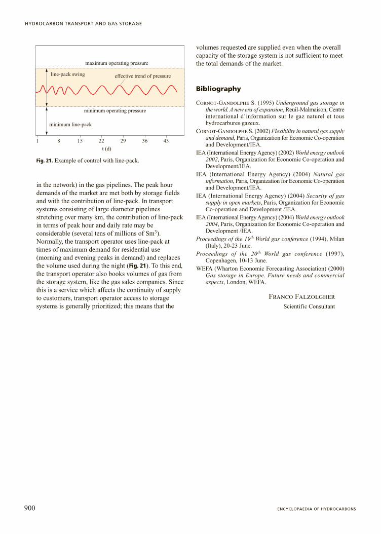
in the network) in the gas pipelines. The peak hourdemands of the market are met both by storage fieldsand with the contribution of line-pack. In transportsystems consisting of large diameter pipelinesstretching over many km, the contribution of line-packin terms of peak hour and daily rate may beconsiderable (several tens of millions of Sm3).Normally, the transport operator uses line-pack attimes of maximum demand for residential use(morning and evening peaks in demand) and replacesthe volume used during the night (Fig. 21). To this end,the transport operator also books volumes of gas fromthe storage system, like the gas sales companies. Sincethis is a service which affects the continuity of supplyto customers, transport operator access to storagesystems is generally prioritized; this means that the
volumes requested are supplied even when the overallcapacity of the storage system is not sufficient to meetthe total demands of the market.
Bibliography
Cornot-Gandolphe S. (1995) Underground gas storage inthe world. A new era of expansion, Reuil-Malmaison, Centreinternational d’information sur le gaz naturel et toushydrocarbures gazeux.
Cornot-Gandolphe S. (2002) Flexibility in natural gas supplyand demand, Paris, Organization for Economic Co-operationand Development/IEA.
IEA (International Energy Agency) (2002) World energy outlook2002, Paris, Organization for Economic Co-operation andDevelopment/IEA.
IEA (International Energy Agency) (2004) Natural gasinformation, Paris, Organization for Economic Co-operationand Development/IEA.
IEA (International Energy Agency) (2004) Security of gassupply in open markets, Paris, Organization for EconomicCo-operation and Development /IEA.
IEA (International Energy Agency) (2004) World energy outlook2004, Paris, Organization for Economic Co-operation andDevelopment /IEA.
Proceedings of the 19th World gas conference (1994), Milan(Italy), 20-23 June.
Proceedings of the 20th World gas conference (1997),Copenhagen, 10-13 June.
WEFA (Wharton Economic Forecasting Association) (2000)Gas storage in Europe. Future needs and commercialaspects, London, WEFA.
Franco FalzolgherScientific Consultant
900 ENCYCLOPAEDIA OF HYDROCARBONS
HYDROCARBON TRANSPORT AND GAS STORAGE
1 8 15 22
t (d)
maximum operating pressure
minimum operating pressure
minimum line-pack
effective trend of pressure
29 36 43
line-pack swing
Fig. 21. Example of control with line-pack.

7.4.2 Underground structures for natural gas storage
IntroductionAs discussed in Section 7.4.1, when a gas field is
brought into production, the surface plants andrequired wells are designed to ensure constantaverage production throughout the years and handlethe inevitable decline of production. The supply ofnatural gas from a number of fields generallyrequires regulation of the relative production forcomprehensive use of the capacities of the majornatural gas pipelines. However, together with theconstant production of gas, there is a variableseasonal demand, higher in winter given the greaterconsumption for heating. The connection betweenconstant supply and variable demand is provided byunderground natural gas storage: when demand islower than supply, excess gas is injectedunderground and is retrieved during periods ofgreater request.
In addition, fields for underground natural gasstorage are generally located near areas where thedemand is greatest and may consist of depleted gasreservoirs, aquifers or artificial caves. Most storage isdone in depleted gas fields, followed by storage inaquifers. On the other hand, storage in artificial caves− while unable to compete with other systems in termsof the amount of gas stored − is becoming quitecommon since it ensures high productivity for shortperiods and very little prior notice, thus meetingsudden demands for gas.
This section will take a closer look at the reservoirstudies ordinarily conducted for gas storage.
Gas storage in depleted gas fieldsWhen a gas field approaches the end of its
productive life, it is advisable to consider transformingit into a gas storage field.
A depleted (or about to be depleted) gas reservoiris generally marked by low pressure and high watersaturation in the zone originally occupied by the gasdue to its displacement by water of the aquifer. Gassaturation behind the water front ranges from aminimum, corresponding to the residual gas saturationnear the original gas/water contact, to a maximum,corresponding to gas saturation near the gas/water
contact in depleted or semi-depleted reservoirs (seeChapters 4.1 and 4.3).
When gas is injected into a depleted reservoir, itdisplaces the water and occupies its place, withouthowever displacing the gas remaining in the poresafter primary gas production. It is important toremember that, thanks to its compressibility, theresidual gas also helps supply the energy neededduring the subsequent production phase. Fig. 1shows the original position of the gas/water contact(AA�) for a water drive gas reservoir and theposition at the end of production (BB�). Afterinjection of the gas, the contact position (CC�)retreats, climbing again during the output phase upto the maximum admissible quota (DD�). Beyondthis level, the storage wells might also producewater, causing serious problems for production andmalfunctioning of the surface equipment. It isimportant to remember that conversion of thedepleted or semi-depleted reservoirs is generally lesscostly than other underground gas storage systemsand has another series of advantages, first andforemost better knowledge of the reservoir’scharacteristics, through both consolidated geologicaldata and the production history of the wells (see alsoSection 7.4.1).
901VOLUME I / EXPLORATION, PRODUCTION AND TRANSPORT
UNDERGROUND STORAGE OF NATURAL GAS
gas storage wells
caprockgas
aquifer
A A�
C C�D D�
B B�
AA�BB�CC�DD�
original gas/water contactgas/water contact before gas storagegas/water contact after gas injectiongas/water contact at the end of a production cycle
Fig. 1. Layout of movement of gas/water contact in underground storage in depleted reservoirs.

Exploitation of a gas field generally requiresthe presence of piping connecting to the linenetwork for gas supply, and surface areas wheregas treatment plants are located. For the purposesof gas storage, these areas can be used for theinstallation of compressors, and for theconstruction of new treatment plants if the old onesare inadequate and impossible to modify.
Not all depleted gas fields are suitable for gasstorage however. Their conformation must be suchthat the gas injected during storage can be recovered
without loss and that the reservoir productivitypromptly meets the demand for gas during theproduction cycle. For that reason, reservoirs withmarked petrophysical heterogeneities or lack ofstructural (displacement due to faults) uniformity orlow permeability are unsuitable.
Pressure/stored volume relationshipLet us consider a volumetric reservoir (without
water drive, see Chapter 4.3) in production. The p/zratio of the average reservoir pressure and the gascompressibility factor to that pressure (z�1 for anideal gas) is, in first approximation, the linear functionof the volume of gas produced, as illustrated in Fig. 2,where A is the initial situation before production and Bis the situation at the end.
In the case of an aquifer drive reservoir (see againChapter 4.3), the p/z ratio is no longer the linearfunction of the gas produced since water enters thepores originally occupied by the gas. The reservoirpressure (and therefore the p/z ratio) tends to begreater with respect to the volumetric reservoir, givenequal volumes of gas produced. Since the aquifershows a delayed response to the drop in pressure of thezone that was originally a gas zone, the deviation fromthe volumetric reservoir is even more apparent after acertain volume of gas has been produced (AB inFig. 3).
In the case of gas injection in a volumetricreservoir, the p/z ratio is the linear function of thevolume of the injected gas (CD in Fig. 4). Instead,with injection of gas in a water drive reservoir, thereservoir pressure (and therefore the p/z) tends to be
902 ENCYCLOPAEDIA OF HYDROCARBONS
HYDROCARBON TRANSPORT AND GAS STORAGE
cumulative gas production
p_z
A
B
Fig. 2. Ratio of pressure p/compressibilityfactor z, versus cumulative production in volumetric reservoirs.
cumulative gas production
p_z
A
B
Fig. 3. Ratio of pressure p/compressibilityfactor z, versus cumulative production in water drive reservoirs.
injected gas volume
p_z
C
D
Fig. 4. Ratio of pressure p/compressibilityfactor z, versus injected gas volume in volumetric gas reservoirs.

initially higher with respect to the volumetricreservoir and tends to become ultimately stabiliseddue to an increase of the volume of the area the gasoccupies following retreat of the water table (CD inFig. 5).
In the case of the reversible storage/productioncycle in the presence of an active aquifer, the trend inthe p/z ratio based on the volume of stored gas is notlinear and generally presents a hysteresis. This isillustrated in Fig. 6, where E is the situation beforeinjection and D is the situation after injection iscompleted.
In the case of a reservoir subjected to one cycle ofinjection and production a year – typical of moststorage systems – the general form of the p/z curvebased on the stored volume is indicated by curveED�DE� in Fig. 7. The section ED� corresponds to theinjection, the section D�D corresponds to pressurestabilization upon completed injection (drop of thepressure in the aquifer); the section DE� correspondsto the output flow phase, the section E�E correspondsto pressure stabilisation at zero production due to thedelay in aquifer response.
The examples give a qualitative, simplifiedidea of the relationship between pressure andproduced/stored gas volume. More preciseanalysis must quantify the influence of the aquiferas well as the not always negligible contribution ofporous volume compressibility. The delay inaquifer response may, in fact, have a noticeableeffect on pressure during the alternating phases ofinjection and production. Moreover, porousvolume compressibility may change significantly
according to pressure, particularly for relativelyshallow, unconsolidated formations. While for aproduction reservoir, the decompression of theporous volume takes place over a number of years,in the case of a storage reservoir, the phases ofcompression and decompression are very rapid,generally lasting less than six months. In this case,the elastic variation of the porous volumefollowing this stress can have a delayedcompensation effect on the reservoir pressure verysimilar to that of an aquifer drive.
903VOLUME I / EXPLORATION, PRODUCTION AND TRANSPORT
UNDERGROUND STORAGE OF NATURAL GAS
injected gas volume
p_z
C
D
Fig. 5. Ratio of pressure p/compressibility factor z, versus injected gas volume in water drive reservoirs.
injected gas volume
p_z
E
D
Fig. 6. Ratio of pressure p/compressibility factor z,versus injected gas volume in an injection/productioncycle in water drive reservoirs.
injected gas volume
p_z
E�
D�
E
D
Fig. 7. Ratio of pressure p/compressibility factor z,versus injected gas volume in a brief storage cycle in water drive reservoirs.

Productivity of a storage reservoir and function of cushion gas
For a gas storage reservoir, the gas volumes thatcan be stored and, above all, those that can bereversibly produced over the limited period of theoutput flow are of great importance. Compared to agas reservoir, whose production is distributed over anumber of years, a storage reservoir must guarantee aproduction of comparable quantities of gasconcentrated over a period of 5-6 months at the most.For that reason, the storage reservoir must have a highlevel of productivity.
Since the wells are the points of gas extraction, ahigh number of wells can clearly lead to highreservoir productivity. Still, given the wells’ highunit cost, it is preferable to use a limited number,making sure that each has high productivity,meaning that relatively high flows shouldcorrespond to limited losses of pressure in thepassage from the reservoir to the surface.Theselosses take place within the porous medium, at theinterface between the reservoir and the borehole andwithin the production string.
These pressure losses in the porous mediumdepend basically on rock permeability and aretherefore not generally susceptible to ameliorativevariations. It is evident that, for this reason,reservoirs with low permeability are difficult toconvert into storage fields. Instead, losses of pressureat the interface between the reservoir and theborehole can be reduced considerably by increasingthe diameter of the borehole and, even more, by usinghorizontal wells wherever conditions allow. Whateverthe case may be, the well drilling and completiontechniques must allow for minimum damage of theformation around the well. Given the high outputdemand, there are significant pressure losses due tofriction within the production string. In order toreduce these losses to a minimum, pipes with a widerdiameter than normally employed for gas reservoirproduction are used.
It should be noted that high flows mean high linearfluid velocity. In the case of poorly consolidatedformations, this can lead to disastrous sand productionin the wells during output flow, something that must betaken into account in well completion design (seeChapter 3.7).
Operating conditions of surface plants being equal,the greater the average reservoir pressure, the greaterthe flow that theoretically can be obtained from the gaswells. Thus, storing gas at higher pressure, means –aside from a greater amount of gas stored – thepossibility of greater initial well productivity, acircumstance that makes a storage project moreattractive. However, the technical limitation for
maximum pressure in injection is that beyond whichthe integrity of the cap rock can no longer be assured,or when there would be an excessive volume of gasstored with migration of gas that escapes beyond thespill point. Legislative limitations also vary fromcountry to country, however: at present in Italy, it ispossible to store gas in a depleted reservoir up to apressure no greater than the original pressure of thevirgin reservoir.
Together with the maximum daily flow rate that thereservoir can provide the network, the gas storagedesign also determines a minimum flow rate necessaryto meet the demand for gas. In order to ensure thisminimum flow, reservoir pressure must not fall belowa set value. The minimum volume of gas in thereservoir, sufficient to supply the needed energy,corresponds to the cushion gas volume. This volumemust always be kept in a storage reservoir since gasoutput flow could lead to poor operative conditions ofsurface plants, causing a dangerous rise in thereservoir water table, and making it impossible to meetcontractual gas supply obligations. It should howeverbe kept in mind that, during emergencies, it is possibleto release part of the cushion gas without creatingproblems by recovering productivity through loweringpressure at the wellheads.
Reservoir simulation for storage optimizationThe simulation of reservoir behaviour with
mathematical models allows to take into account theaquifers, the variations of the porous volume, and therelative motion of water and gas, governed by therelative permeability curves. The use of numericalmodels of finite differences also makes it possible totake into account reservoir heterogeneities, and thepossibility of intercommunication between the variouslevels. In particular, using the history matchingtechnique (a comparison between the history ofproduction and model data, see Chapter 4.6), byadjusting reservoir and well parameters, ourunderstanding of the reservoir deepens as thehistorical data increases.
It is obvious that a ‘mature’ gas reservoir (in anadvanced state of exploitation) has a large amount ofhistorical data to reproduce and therefore its studyleads to a thorough understanding of the reservoir,essential for injecting gas for storage. Optimizedtransformation of a depleted reservoir into a storagereservoir necessitates a study that reasonablyreproduces historical production data over time for allthe wells: bottom hole pressure, wellhead pressure, gasproduction, initial moment of water production,amount of water produced. An example of the historymatching of pressure data for a gas well is given in Fig. 8.
904 ENCYCLOPAEDIA OF HYDROCARBONS
HYDROCARBON TRANSPORT AND GAS STORAGE

Using reservoir characteristics adjusted whenperforming history matching, it is therefore possible tocarry out mathematical model simulations of storageunder different scenarios. That way, we can take intoaccount a number of variable wells in differentlocations and completions as well as surface plantoperation conditions. These simulations allow
evaluation of how the reservoir might respond toalternating phases of the injection/production flowcycle, particularly vis-à-vis the aquifer’s response andrelative cyclical movements of the water table.
The information obtained helps to formulate aneconomic evaluation that is helping in confirming thefeasibility of a project for new storage system or formodifying an existing one. A graphic example of thisdata is seen in Figs. 9, 10, and 11. Figs. 9 and 10 showthe trends of the gas over time for volume stored in thedepleted reservoir and the gas pressure, simulatedduring the alternating phases of the storage and outputflow cycles. It should be observed that, beforebeginning output flow/injection, a minimum amountof gas is injected in the reservoir, and the amount ofstored gas and the reservoir pressures must never fallbelow specific values. The potential outflow of gas ina general storage cycle is known as the working gas.The amount of gas that remains stored in a reservoir isthe cushion gas. The drift observed in Fig. 9 dependson the fact that part of the energy supplied in injectionfor re-creation of the gas reservoir is graduallydissipated with pressurisation of the aquifer, whichresponds more slowly than the gas zone. Fig. 11shows, for an average flow cycle, the curve of theoutput flow that the reservoir can assure, based on thevolume of the output flow. This curve best describes areservoir’s capacity to meet the production demand.Generally speaking, for reservoirs that – properlyregulated – contribute an average constant supply tothe available gas pipeline network, the maximum flowcan remain constant up to an outflow of 30-40% of theworking gas.
In order to meet sudden spurts of high userdemand for gas, high production reservoirs – oftencharacterized with a low working gas value – are used;their productivity curves may have a plateau ofmaximum flow lower than 10% of the working gas.
905VOLUME I / EXPLORATION, PRODUCTION AND TRANSPORT
UNDERGROUND STORAGE OF NATURAL GAS
1981
200
150
100
50
01986 1991 1996 2001
pres
sure
(ba
r)
years
simulated bottom hole pressuremeasured bottom hole pressuresimulated wellhead pressuremeasured wellhead pressure
Fig. 8. Example of history matching to reproduce well pressure.
300
350
250
200
150
100
50
0
gas
volu
me
(MS
m3 )
time
06-0
1-01
08-0
1-01
10-0
1-01
12-0
1-01
14-0
1-01
16-0
1-01
18-0
1-01
20-0
1-01
22-0
1-01
24-0
1-01
26-0
1-01
28-0
1-01
Fig. 9. Trend of gas volume stored over time for a storage project.
200
150
100
50
0
pres
sure
(ba
r)
time
06-0
1-01
08-0
1-01
10-0
1-01
12-0
1-01
14-0
1-01
16-0
1-01
18-0
1-01
20-0
1-01
22-0
1-01
24-0
1-01
26-0
1-01
28-0
1-01
Fig. 10. Trend of reservoir pressure over time for a storage project.

Gas storage in the aquifersAquifers, underground geological formations, bent
over so that they can constitute a trap but having waterinside the pores, are generally characterised byexcellent porosity and high permeability. Theirextension may be significant. If they meet theconditions for gas trapping, these formations can beused as gas storage fields. Natural gas storage in theaquifers requires injection of gas inside a porousmedium initially containing only water. The gasinjected in the structure top displaces the water and,thanks to the effect of differences in density,accumulates at the top of the structure.
Requisites It is important to underline that not all aquifers are
suitable for natural gas storage: the basic requisites aretheir ability to store gas without loss and producestored gas with high productivity. For that reason,thorough knowledge of the structure is required,supported by good seismic and geological control. Inthe case of an anticline, the position of the spill pointthat guarantees maximum trapping must be welldefined, nor should there be any dislocations (faults)that can impede hydraulic continuity in the porousmedium or act as a path for gas leakage. Imperfectknowledge of the structure might lead – during the gasinjection phase – to a loss of gas beyond the spillpoint, towards other structures, or even to the surface.In addition, the aquifer’s cap rock must have a certainthickness and characteristics that will ensure perfectgas tightness against the higher pressures requiredduring storage.
Uniformity of the petrophysical characteristics ofthe reservoir rock is also important. If there is notuniform, fingering – i.e. preferential injection of gas inthe most permeable layers – could occur during gasinjection, thus making it impossible to separate the gasitself at the structural top due to its lower gravity. Inthat case, ‘islands’ of rock, containing water not
displaced by the gas, would remain behind the gasfront, with a negative impact on well productivityduring output flow of the stored gas with undesiredproduction of water.
Good gas productivity thus also requires that theaquifer be of high permeability, not too close to thesurface and with a sufficiently high initial pressure.Once the process of storage/production is operatingregularly, it is advisable that the maximum bottomhole pressure not be too different from the originalpressure. It is obvious that the greater the reservoirpressure during storage, the greater the amount of gasthat can be stored and the greater the maximum dailyflow rate of gas obtainable during the initial outputphase.
OperationIt is important to underline that, before the creation
of the first gas chamber, the porous medium iscompletely saturated with water. Under thesecircumstances, in order to introduce the gas (fluid gasthat does not wet the rock), a differential pressure withrespect to the water must be applied to the gascorresponding to the gas/water capillary pressure (seeChapter 4.1). In addition, due to the effect caused bythe gas/water relative permeability curves, whichunder these conditions indicate low effectivepermeability to gas, initially it is necessary to usehigher injection pressures than the maximum pressureused during regular storage. Due to the greater area ofcontact with the area completely saturated with water,the pressure needed to displace the water tends todecrease considerably once a first bank of gas iscreated around the well, as described by Darcy’s law.
It should also be pointed out that, in order toconvert an aquifer into a gas storage field, part of thecushion gas injected before the reversibleinjection/output flow operations remains inside thepore, and is impossible to recover physically eventhough it is part of the drive mechanism. In fact,supposing that the remaining gas can be recovered atthe end of the storage operations, a residual volumeof gas – impossible to recover in any way whatsoever– will remain inside the pore behind the displacedwater front.
CharacterizationIn contrast to depleted gas reservoirs whose past
production history supplies the instruments needed forbest understanding of the reservoir, in the case ofaquifers, initial reservoir knowledge is basedexclusively on seismic-geological data and the littleexisting well data. For that reason, when countrylegislation allows storage in aquifers, knowledge of thestructure and hydraulic continuity of the porous
906 ENCYCLOPAEDIA OF HYDROCARBONS
HYDROCARBON TRANSPORT AND GAS STORAGE
1.4
1.2
1.0
0.8
0.6
0.4
0.20
0 20 40 60 80 100 120 140
flow
rat
e (M
Sm3 /
d)
output volume (MSm3)
Fig. 11. Deliverability curve of a reservoir for a storage project.

medium should be obtained before conversion throughdrilling of suitably distributed key wells. Petrophysicalcharacterisation of the reservoir should therefore becarried out on rock samples obtained duringcontinuous coring. Aside from permeability andporosity measurements carried out on these samples,useful tests include compressibility of the reservoirrock and determination of the characteristics of the caprock’s tightness, marked by the threshold pressurebeyond which the gas can migrate vertically throughthe cap rock itself.
The study of an aquifer already transformed intostorage reservoir, performed with the history matchingtechnique on the basis of an historical number ofstorage-flow cycles, is a basic instrument both for thebetter knowledge of the reservoir and the periodicverification of the inventory (volumes, pressures, etc.)of the gas stored.
Storage in artificial cavitiesUnderground storage of natural gas can also be
carried out in cavities created inside accumulations ofsalt through artificial washing with water. Theseaccumulations are present in nature in two forms: saltdomes and salt beds. Salt domes are the result of theplastic deformation of salt which has been pressedupwards with time through weak points in thesediment due to the pressure of sediments above it andthe difference of density. They are generally oblong inshape and vertical and can reach horizontal diametersof over a kilometre, rising up to several kilometres inheight. Salt domes are generally used to store naturalgas and are found at a depth of between 500 and 2,000metres. Salt beds on the other hand are extendedformations, consisting of alternating formations of saltand other evaporitic rocks: they can reach a thicknessof 500 metres, while they are generally no deeper than1,000 metres.
Salt accumulations consist of almost pure sodiumchloride generally employed for industrial purposesand which may be extracted with traditional miningmethods (underground mining) or controlleddissolving with fresh water. Thanks to the lattermethods, saturated saline solutions may be obtainedand used directly in chlorine and caustic soda plants.The salt’s impermeability makes the cavities obtainedthis way excellent for storage of materials where salt isinsoluble (saturated saltwater drilling mud, liquid andgaseous hydrocarbons, ecc.).
The use of artificial salt caves to storehydrocarbons is relatively recent, starting in Canada atthe beginning of the Second World War and continuingduring the 1950s in North America and Europe withthe storage of LPG. During the 1980s, the UnitedStates created strategic reserves of oil inside salt
formations with a stored volume of 94 million cubicmetres. The storage of gas inside salt cavities startedlater, in the United States during the 1960s.
The caves are not very large: average volumes runfrom 50,000 to 500,000 m3, although recently newtechnologies have allowed construction of cavitiesover 300 m in length with capacities of up to2,500,000 m3.
Notes on the construction of artificial salt cavernsNot all caves originally used for salt extraction are
suitable for gas storage: the cavities may have aparticular shape that could lead to internal collapseduring storage operations (injection and output flow)with consequential safety problems. If the salt washinggenerates a lateral peak higher than the base of the lastwell casing, it might be impossible to recover the gasthat occupies it during removal of the salt water,making well recompletion procedures extremelydifficult.
Before developing a cave, we must first know theshape of the embedded rock of the salt deposit, anddetermine the availability of both water for saltdissolution and sites for disposal of the salt water. Thegeometry and internal consistency of the accumulationof salt can be identified (if not already known throughprevious geological and geophysical studies for oilprospecting) by means of geoseismic surveys and testwell drilling with continuous coring of the formations.
It should be kept in mind that salt dissolution canalso be performed using brackish water with a low saltcontent, which increases its availability. When not sentto chlorine-soda production plants operating in thearea, salt water is generally disposed of inunderground formations.
The well drilled for the construction of the cave isthe same that will be later used for storage operations.The drilling mud must be saturated with salt in orderto ensure integrity of the hole inside the salt. Afterinstallation of suitable casing, the well is completedwith two concentric tubes (Fig. 12): fresh or brackishwater is generally injected from the inner pipe. Thegap between this and the successive pipe is used to letout the salt water and the gap between external tubingand casing, is used to create an oil blanket above theaqueous phase, in order to keep fresh water fromcoming into contact with the roof of the cave underconstruction, and avoid the unwanted formation of anupper-side culmination. As the salt is dissolved, theinner pipe is lowered further to allow greater contactbetween the water and salt. The cavity formed isoblong and pear-shaped, with a wider base section anddebris accumulating on the bottom. If watercirculation is inverted, with extraction from the innerpipe, the cavity tends to adopt a wider top section.
907VOLUME I / EXPLORATION, PRODUCTION AND TRANSPORT
UNDERGROUND STORAGE OF NATURAL GAS

Cave design is generally done with the help ofmathematical models that take into account thethermodynamic properties of the salt and the waterused. Control of dimensions is done during saltdissolution through acoustic instruments such as sonar.Once a cave of the desired size is obtained, it isemptied using the same gas that will be stored in it. Itshould be noted that debris and part of the salt watercannot be completely eliminated and remain at thebase of the cave. During storage, this water tends tovapourize in the gas making it necessary for the gasproduced to be dehydrated before being sent to the gaspipelines.
In order to construct a cave with a volume of about400,000 m3, roughly ten times the volume of water isneeded; construction time, with an optimum flow ofwater of 300 m3/h, is approximately 20 months. The
average life span of a cave for gas storage operations isabout 30 years.
Characteristics of salt cavern storageSince they are completely impermeable, artificial
salt caverns are ideal gas containers. In contrast toother storage systems in porous mediums, salt cavernstorage presents very high productivity which meansthat the caves can be used specifically for profitablepeak shaving operations. In fact, in emergencysituations or in the case of a sudden demand, the gascan immediately be released into the network. Storageoperations are also much faster than with othersystems. For these reasons, it is possible to haveseveral injection/output cycles a year, marked inaverage by a high output for 5-10 days and injectionfor 10-20 days. Another advantage is the use of loweramounts of cushion gas to ensure well productivityduring the output phase (30-40% as compared to anaverage of 50%, typical of storage in depletedreservoirs).
Given the limited volume of gas that can be stored(and therefore the limited volume of working gas),storage in artificial caverns cannot compete with otherstorage systems as regards supply of relativelyconstant flows in the periods of maximum gasdemand.
The maximum pressure of cavern storage does notgenerally exceed a gradient of 19,600 Pa (0.2 kg/cm2)per metre of depth, starting from the cave roofpressure. The minimum pressure during output islimited by geomechanical considerations: with time,stress due to sharp changes in pressure can lead toplastic deformation of the salt, even causing a sizeablereduction of the artificial cave’s volume. As anempirical rule, it is advisable to keep minimumpressure during output from dropping below a gradientof 8,800 Pa (0.09 kg/cm2) per metre of depth startingfrom the pressure at the cave roof.
Well typologies and completion in the gas storage fields
Use of existing completions for injection/productionIn the case of transformation of depleted gas
reservoirs into storage reservoirs, the tendency – ifthe mechanical conditions of the wells allow it and ifthe location is in the structural top – is to reuse thewells with existing completions both for injectionoperations and production. It should be kept in mindthat the existing wells that cannot be used directly forstorage are still an important source of informationfor storage control thanks to reservoir studies. Usedas monitoring wells, they can supply preciousinformation on the trends of reservoir pressure and
908 ENCYCLOPAEDIA OF HYDROCARBONS
HYDROCARBON TRANSPORT AND GAS STORAGE
fresh watersalty water
oilshallow formations
outletsaltywater
inletfreshwater
rubble
salt
oil blanket
Fig. 12. Building plan of an artificial salt cavefor gas storage.

even on the movement of the water table duringinjection/output operations.
Modification to existing completions During gas injection, in order to overcome pressure
loss along the path to the reservoir, wellhead pressuremust be higher than during production. For thatreason, the wellhead equipment must be renderedcompatible with the injection conditions. Moreover, itis often convenient to proceed to recompletion ofexisting wells to meet the new demand for highproductivity during the output cycle. In fact, in orderto reduce the pressure loss, recompletion with pipes ofgreater internal diameter may be necessary.
With high output flows and with fairlyunconsolidated formations, it is possible that sand isdrawn into the well, due to high velocity of gas flow atthe interface between the casing and the formation. Inorder to avoid sanding of the well and the start ofdangerous abrasion and breakage within the pipes,filters are generally used (gravel packs in particular:see Chapter 6.2), which must be installed with extremecare to reduce damage and loss of internal pressure asmuch as possible.
New completionsWhen the use of existing wells, even if modified
during completion, does not allow the productivitydemanded during output of the storage reservoir,additional wells must be drilled. It is obvious thatwells designed ad hoc for storage reservoirs operationsare more suitable than recovered wells not designedfor this purpose. The use of horizontal well atstructural tops can generally, despite high unit costs,meet the double goal of guaranteeing high productivityand minimizing the number of wells needed. However,the complex morphology of reservoirs and thepresence of active aquifers and heterogeneities in theporous medium justify the development of storagewith conventional wells.
The study of the reservoir by mathematicalsimulation makes it possible to calculate the numberof wells needed, the sections of the tubing best suitedto storage operations and the maximum head pressureduring injection of the gas in the reservoir. Wellcompletions are designed with this in mind. Most ofall, the well must be capable of operating in constantsafety and reduce the possibility of accidentalinterruption of production to a minimum.
Fig. 13 shows a typical storage well completion: thegravel pack is present at the bottom in the open hole,and the mechanical filter is inserted in it at the base ofthe tubing. After that comes the production packer, thesurface controlled subsurface safety valve thatautomatically closes the well in the case of a sudden
rise in flow. Above that lies the glycol injection valveto prevent the formation of hydrate plugs inside thetubing. The completion ends with the wellhead,designed for a maximum pressure that is greater thanthe maximum pressure predicted during gas injection.
909VOLUME I / EXPLORATION, PRODUCTION AND TRANSPORT
UNDERGROUND STORAGE OF NATURAL GAS
conductorpipe
injection
production
casing
casing
productionpacker
productiontubing
filter
gravel pack
formation
packer
glycolinjection
valve
safetyvalve
circulationvalve
Fig. 13. Completion scheme for a gas storage well.

Bibliography
Aziz K., Settari A. (1979) Petroleum reservoir simulation,London, Applied Science Publishers.
Baldini G. (1963) Elementi introduttivi alla coltivazione deigiacimenti di idrocarburi, Torino, Libreria EditriceUniversitaria.
Bornemann O. et al. (2001) Characterisation of sites for saltcaverns in the middle European Zechstein salt using basinexploration experiences of the Gorleben salt dome, in:Proceedings of the Solution Mining Research Institute Fall2001 meeting, Albuquerque (NM), 8-10 October.
Chierici G.L. (1989) Principi di ingegneria dei giacimentipetroliferi, Agip, 2v.
Craft B.C., Hawkins M.F. (1959) Applied petroleum reservoirengineering, Englewood Cliffs (NJ), Prentice Hall.
Frick T.C., Taylor R.W. (1962) Petroleum productionhandbook, New York, McGraw-Hill, 2v.
Tek M.R. (1996) Natural gas underground storage. Inventoryand deliverability, Tulsa (OK), PennWell.
Thoms R.L., Gehle R.M. (2000) A brief history of salt cavernuse, in: Proceedings of the 8th World salt symposium, TheHague, 7-11 May, v. I, 207-214.
Gianfranco Altieri Scientific Consultant
910 ENCYCLOPAEDIA OF HYDROCARBONS
HYDROCARBON TRANSPORT AND GAS STORAGE