7350 SERIES CONVEYORS...7350 series belted conveyors profiles & guiding page 20 modular belt...
76
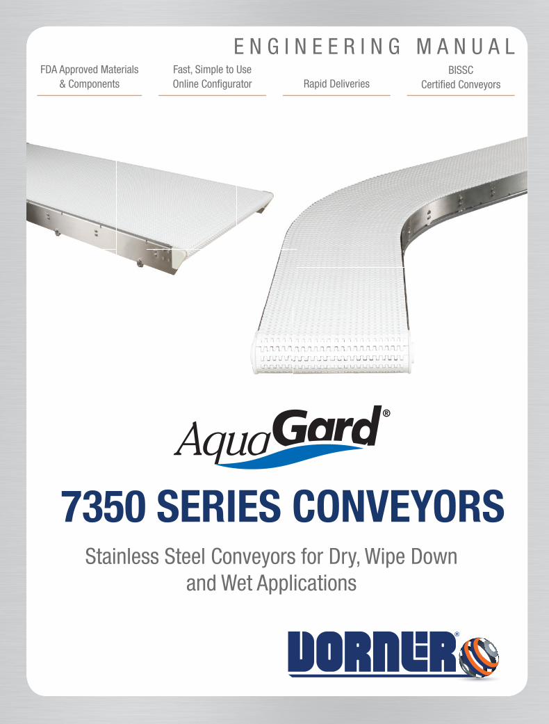
Fast, Simple to Use Online Configurator Rapid Deliveries BISSC Certified Conveyors FDA Approved Materials & Components Stainless Steel Conveyors for Dry, Wipe Down and Wet Applications 7350 SERIES CONVEYORS ENGINEERING MANUAL
Transcript of 7350 SERIES CONVEYORS...7350 series belted conveyors profiles & guiding page 20 modular belt...
Fast, Simple to Use Online Confi gurator Rapid Deliveries
BISSCCertifi ed Conveyors
FDA Approved Materials & Components
Stainless Steel Conveyors for Dry, Wipe Downand Wet Applications
7350 SERIES CONVEYORS
E N G I N E E R I N G M A N U A L
7350SERIES
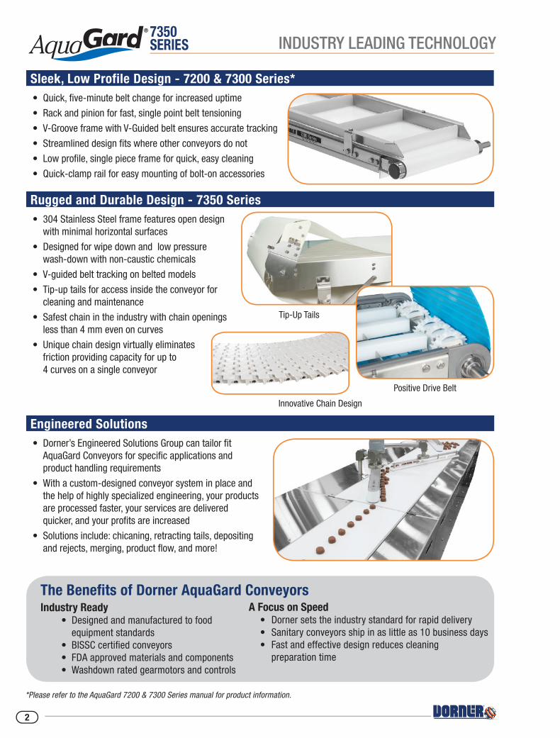
Rugged and Durable Design - 7350 Series• 304 Stainless Steel frame features open design with minimal horizontal surfaces
• Designed for wipe down and low pressure wash-down with non-caustic chemicals
• V-guided belt tracking on belted models
• Tip-up tails for access inside the conveyor for cleaning and maintenance
• Safest chain in the industry with chain openings less than 4 mm even on curves
• Unique chain design virtually eliminates friction providing capacity for up to 4 curves on a single conveyor
Sleek, Low Profile Design - 7200 & 7300 Series*• Quick, fi ve-minute belt change for increased uptime
• Rack and pinion for fast, single point belt tensioning
• V-Groove frame with V-Guided belt ensures accurate tracking
• Streamlined design fi ts where other conveyors do not
• Low profi le, single piece frame for quick, easy cleaning
• Quick-clamp rail for easy mounting of bolt-on accessories
Engineered Solutions• Dorner’s Engineered Solutions Group can tailor fi t AquaGard Conveyors for specifi c applications and product handling requirements
• With a custom-designed conveyor system in place and the help of highly specialized engineering, your products are processed faster, your services are delivered quicker, and your profi ts are increased
• Solutions include: chicaning, retracting tails, depositing and rejects, merging, product fl ow, and more!
The Benefi ts of Dorner AquaGard ConveyorsIndustry Ready • Designed and manufactured to food equipment standards • BISSC certifi ed conveyors • FDA approved materials and components • Washdown rated gearmotors and controls
A Focus on Speed • Dorner sets the industry standard for rapid delivery • Sanitary conveyors ship in as little as 10 business days • Fast and effective design reduces cleaning preparation time
Tip-Up Tails
Positive Drive Belt
Innovative Chain Design
*Please refer to the AquaGard 7200 & 7300 Series manual for product information.
INDUSTRY LEADING TECHNOLOGY
2

7350SERIES
BELTED CONVEYORS PROFILES & GUIDING PAGE 20
MODULAR BELTCONVEYORS PAGE 28-39
GEARMOTOR MOUNTING PACKAGESPAGE 44-45
CONTROLS PAGE 49
POSITIVE DRIVE CONVEYORS PAGE 16-19
BELTED CONVEYORS PAGE 4-15
TECHNICAL DATA & CALCULATIONSPAGE 56-74
GEARMOTORS PAGE 47-48
FABRIC BELTS & POSITIVE DRIVE BELTS PAGE 21-25
BELT SPEED CHARTSPAGE 46
ACCESSORIESPAGE 54-55
SUPPORT STANDS& ACCESSORIES PAGE 50-53
MODULAR BELTSPAGE 42-43
MODULAR BELT CONVEYORS PROFILES & GUIDING PAGE 40-41
POWERED TRANSFERPAGE 35
TABLE OF CONTENTS
3
7350SERIES
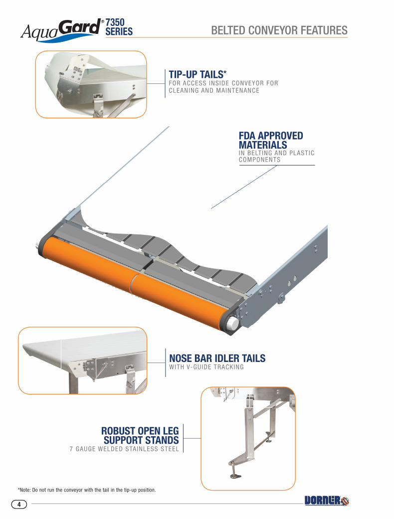
*Note: Do not run the conveyor with the tail in the tip-up position.
NOSE BAR IDLER TAILS WITH V-GUIDE TRACKING
FDA APPROVED MATERIALSIN BELT ING AND PLASTIC COMPONENTS
ROBUST OPEN LEG SUPPORT STANDS
7 GAUGE WELDED STAINLESS STEEL
TIP-UP TAILS* FOR ACCESS INS IDE CONVEYOR FOR CLEANING AND MAINTENANCE
BELTED CONVEYOR FEATURES
4
7350SERIES
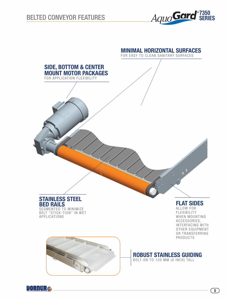
STAINLESS STEEL BED RAILSSEGMENTED TO MIN IMIZE BELT "ST ICK-T ION" IN WET APPL ICAT IONS
SIDE, BOTTOM & CENTER MOUNT MOTOR PACKAGES FOR APPL ICATION FLEX IB IL ITY
FLAT SIDES ALLOW FOR FLEXIB IL ITY WHEN MOUNTING ACCESSORIES, INTERFACING WITH OTHER EQUIPMENT OR TRANSFERRING PRODUCTS
MINIMAL HORIZONTAL SURFACES FOR EASY TO CLEAN SANITARY SURFACES
ROBUST STAINLESS GUIDING BOLT-ON TO 150 MM (6 INCH) TALL
BELTED CONVEYOR FEATURES
5
7350SERIES
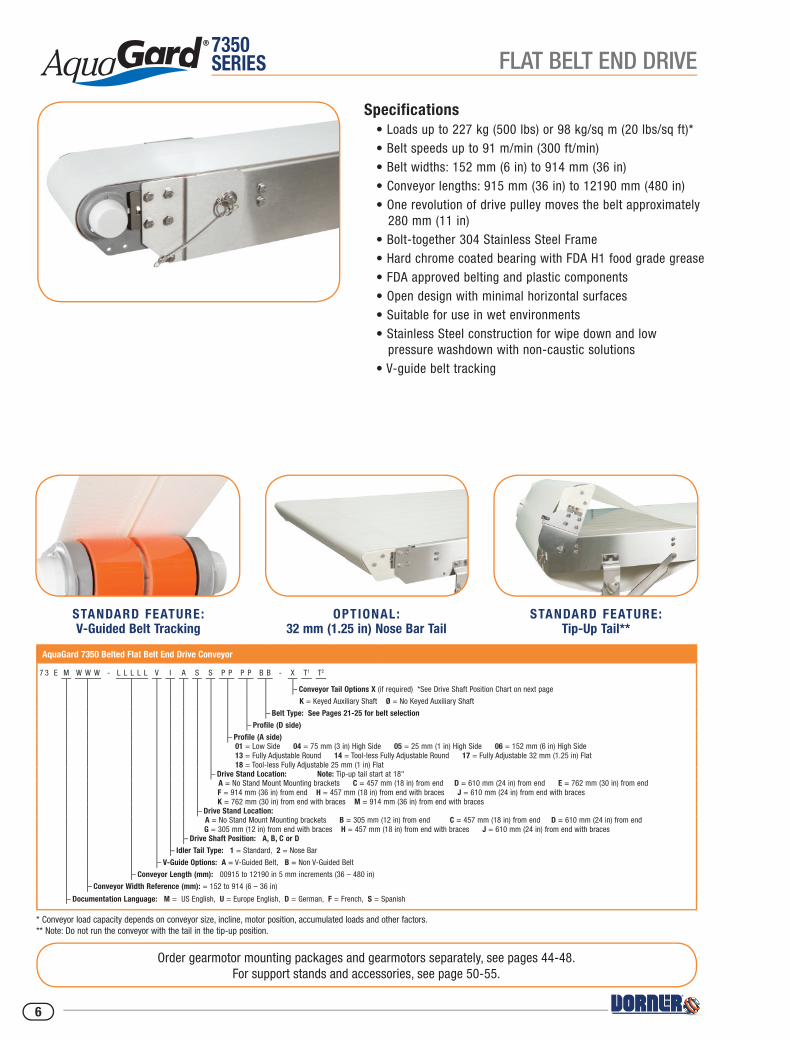
Specifications• Loads up to 227 kg (500 lbs) or 98 kg/sq m (20 lbs/sq ft)*• Belt speeds up to 91 m/min (300 ft/min)• Belt widths: 152 mm (6 in) to 914 mm (36 in)• Conveyor lengths: 915 mm (36 in) to 12190 mm (480 in)• One revolution of drive pulley moves the belt approximately 280 mm (11 in)• Bolt-together 304 Stainless Steel Frame• Hard chrome coated bearing with FDA H1 food grade grease• FDA approved belting and plastic components• Open design with minimal horizontal surfaces• Suitable for use in wet environments• Stainless Steel construction for wipe down and low pressure washdown with non-caustic solutions• V-guide belt tracking
Order gearmotor mounting packages and gearmotors separately, see pages 44-48.For support stands and accessories, see page 50-55.
STANDARD FEATURE: V-Guided Belt Tracking
AquaGard 7350 Belted Flat Belt End Drive Conveyor
7 3 E M W W W - L L L L L V I A S S P P P P B B - X T1 T2
– Conveyor Tail Options X (if required) *See Drive Shaft Position Chart on next page
K = Keyed Auxiliary Shaft Ø = No Keyed Auxiliary Shaft
– Belt Type: See Pages 21-25 for belt selection
– Profile (D side)
– Profile (A side) 01 = Low Side 04 = 75 mm (3 in) High Side 05 = 25 mm (1 in) High Side 06 = 152 mm (6 in) High Side 13 = Fully Adjustable Round 14 = Tool-less Fully Adjustable Round 17 = Fully Adjustable 32 mm (1.25 in) Flat 18 = Tool-less Fully Adjustable 25 mm (1 in) Flat
– Drive Stand Location: Note: Tip-up tail start at 18" A = No Stand Mount Mounting brackets C = 457 mm (18 in) from end D = 610 mm (24 in) from end E = 762 mm (30 in) from end F = 914 mm (36 in) from end H = 457 mm (18 in) from end with braces J = 610 mm (24 in) from end with braces K = 762 mm (30 in) from end with braces M = 914 mm (36 in) from end with braces
– Drive Stand Location: A = No Stand Mount Mounting brackets B = 305 mm (12 in) from end C = 457 mm (18 in) from end D = 610 mm (24 in) from end G = 305 mm (12 in) from end with braces H = 457 mm (18 in) from end with braces J = 610 mm (24 in) from end with braces
– Drive Shaft Position: A, B, C or D
– Idler Tail Type: 1 = Standard, 2 = Nose Bar
– V-Guide Options: A = V-Guided Belt, B = Non V-Guided Belt
– Conveyor Length (mm): 00915 to 12190 in 5 mm increments (36 – 480 in)
– Conveyor Width Reference (mm): = 152 to 914 (6 – 36 in)
– Documentation Language: M = US English, U = Europe English, D = German, F = French, S = Spanish
OPTIONAL: 32 mm (1.25 in) Nose Bar Tail
STANDARD FEATURE:Tip-Up Tail**
* Conveyor load capacity depends on conveyor size, incline, motor position, accumulated loads and other factors.** Note: Do not run the conveyor with the tail in the tip-up position.
FLAT BELT END DRIVE
6
7350SERIES
W =
Con
veyo
r Bel
t Wid
th
Dim
= m
m (i
n)
Driv
e Sh
aft P
ositi
on
Sinc
e be
lts a
re b
eing
pul
led,
pos
ition
s A
& D
are
pref
erre
d. P
ushi
ng b
elts
(B &
C) r
educ
es c
onve
yor
load
cap
acity
by
appr
oxim
atel
y 66
%.
STA
NDAR
D SI
ZES
Conv
eyor
Wid
th R
efer
ence
152
203
254
305
356
406
457
508
559
610
660
711
762
813
864
914
Conv
eyor
Bel
t Wid
th (W
)15
220
325
430
535
640
645
750
855
961
066
071
176
281
386
491
4
(6)
(8)
(10)
(12)
(14)
(16)
(18)
(20)
(22)
(24)
(26
(28)
(30)
(32)
(34)
(36)
Conv
eyor
Len
gth
Refe
renc
e00
915
0000
5 in
crem
ents
up
to…
1219
0
Conv
eyor
Len
gth
(L)
0091
5 (3
6)00
005
(0.2
) inc
rem
ents
up
to…
1219
0 (4
80)
FLOW
168 m
m [6.
63 in
]99
mm
[3.89
in]
R45 m
m [R
1.78 i
n]10
6 mm
[4.19
in]
L
WW
+68 m
m [2.
67 in
]
55 m
m [2.
18 in
]25
mm
[1.00
in] D
IA. S
HAFT
WITH
6 mm
[0.25
] KEY
WAY
205 m
m [8.
06 in
]
OPTIO
NAL N
OSE B
AR TA
IL
121 m
m[4.
76 in
]
R17 m
m [R
0.68 i
n]
144 m
m[4.
49 in
]
Posit
ion A
Posit
ion D
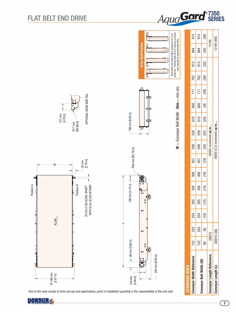
Due to the wide variety of drive set ups and applications, point of installation guarding is the responsibility of the end user.
FLAT BELT END DRIVE
7
7350SERIES
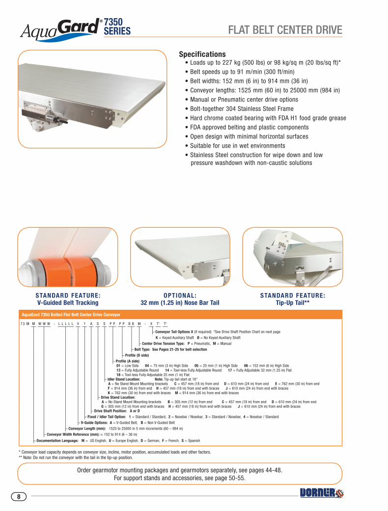
Specifications• Loads up to 227 kg (500 lbs) or 98 kg/sq m (20 lbs/sq ft)*• Belt speeds up to 91 m/min (300 ft/min)• Belt widths: 152 mm (6 in) to 914 mm (36 in)• Conveyor lengths: 1525 mm (60 in) to 25000 mm (984 in)• Manual or Pneumatic center drive options• Bolt-together 304 Stainless Steel Frame• Hard chrome coated bearing with FDA H1 food grade grease• FDA approved belting and plastic components• Open design with minimal horizontal surfaces• Suitable for use in wet environments• Stainless Steel construction for wipe down and low pressure washdown with non-caustic solutions
Order gearmotor mounting packages and gearmotors separately, see pages 44-48.For support stands and accessories, see page 50-55.
AquaGard 7350 Belted Flat Belt Center Drive Conveyor
73 M M W W W - L L L L L V 1 A S S P P P P B B M - X T1 T2
– Conveyor Tail Options X (if required) *See Drive Shaft Position Chart on next page
K = Keyed Auxiliary Shaft Ø = No Keyed Auxiliary Shaft
– Center Drive Tension Type: P = Pneumatic, M = Manual
– Belt Type: See Pages 21-25 for belt selection
– Profile (D side)
– Profile (A side) 01 = Low Side 04 = 75 mm (3 in) High Side 05 = 25 mm (1 in) High Side 06 = 152 mm (6 in) High Side 13 = Fully Adjustable Round 14 = Tool-less Fully Adjustable Round 17 = Fully Adjustable 32 mm (1.25 in) Flat 18 = Tool-less Fully Adjustable 25 mm (1 in) Flat
– Idler Stand Location: Note: Tip-up tail start at 18" A = No Stand Mount Mounting brackets C = 457 mm (18 in) from end D = 610 mm (24 in) from end E = 762 mm (30 in) from end F = 914 mm (36 in) from end H = 457 mm (18 in) from end with braces J = 610 mm (24 in) from end with braces K = 762 mm (30 in) from end with braces M = 914 mm (36 in) from end with braces
– Drive Stand Location: A = No Stand Mount Mounting brackets B = 305 mm (12 in) from end C = 457 mm (18 in) from end D = 610 mm (24 in) from end G = 305 mm (12 in) from end with braces H = 457 mm (18 in) from end with braces J = 610 mm (24 in) from end with braces
– Drive Shaft Position: A or D
– Fixed / Idler Tail Option: 1 = Standard / Standard, 2 = Nosebar / Nosebar, 3 = Standard / Nosebar, 4 = Nosebar / Standard
– V-Guide Options: A = V-Guided Belt, B = Non V-Guided Belt
– Conveyor Length (mm): 1525 to 25000 in 5 mm increments (60 – 984 in)
– Conveyor Width Reference (mm): = 152 to 914 (6 – 36 in)
– Documentation Language: M = US English, U = Europe English, D = German, F = French, S = Spanish
* Conveyor load capacity depends on conveyor size, incline, motor position, accumulated loads and other factors.** Note: Do not run the conveyor with the tail in the tip-up position.
STANDARD FEATURE: V-Guided Belt Tracking
OPTIONAL: 32 mm (1.25 in) Nose Bar Tail
STANDARD FEATURE:Tip-Up Tail**
FLAT BELT CENTER DRIVE
8

7350SERIES
W =
Con
veyo
r Bel
t Wid
th
Dim
= m
m (i
n)
Driv
e Sh
aft P
ositi
on
STA
NDAR
D SI
ZES
Conv
eyor
Wid
th R
efer
ence
152
203
254
305
356
406
457
508
559
610
660
711
762
813
864
914
Conv
eyor
Bel
t Wid
th (W
)15
220
325
430
535
640
645
750
855
961
066
071
176
281
386
491
4
(6)
(8)
(10)
(12)
(14)
(16)
(18)
(20)
(22)
(24)
(26
(28)
(30)
(32)
(34)
(36)
Conv
eyor
Len
gth
Refe
renc
e01
525
0000
5 in
crem
ents
up
to…
2500
0
Conv
eyor
Len
gth
(L)
0152
5 (6
0)00
005
(0.2
) inc
rem
ents
up
to…
2500
0 (9
84)
W
L
252 m
m [9.
92 in
]
W +
68 m
m[2.
67 in
]
25 m
m [1.
00 in
] DIA
. SHA
FT
WITH
6 mm
[0.25
in] (6
) KEY
WAY
310 m
m[12
.22 in
]
604 m
m [23
.78 in
]
151 m
m [5.
94 in
]
FLOW
OPTIO
NAL N
OSE B
AR TA
IL
121 m
m [4.
76 in
]
R17 m
m [R
0.68 i
n.]
W +
170 m
m [6.
69 in
]
172 m
m [6.
76 in
]
114 m
m [4.
49 in
]
144 m
m [5.
68 in
]
Posit
ion A
Posit
ion D
Due to the wide variety of drive set ups and applications, point of installation guarding is the responsibility of the end user.
FLAT BELT CENTER DRIVE
9
7350SERIES
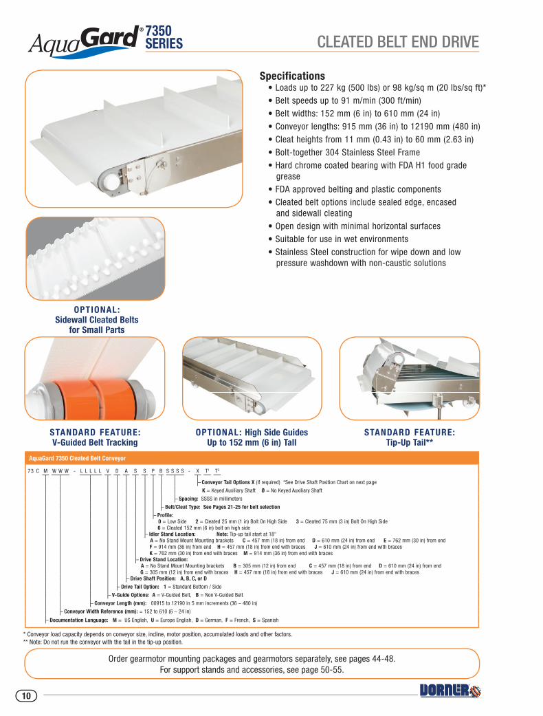
Specifications• Loads up to 227 kg (500 lbs) or 98 kg/sq m (20 lbs/sq ft)*• Belt speeds up to 91 m/min (300 ft/min)• Belt widths: 152 mm (6 in) to 610 mm (24 in)• Conveyor lengths: 915 mm (36 in) to 12190 mm (480 in)• Cleat heights from 11 mm (0.43 in) to 60 mm (2.63 in)• Bolt-together 304 Stainless Steel Frame• Hard chrome coated bearing with FDA H1 food grade grease• FDA approved belting and plastic components• Cleated belt options include sealed edge, encased and sidewall cleating• Open design with minimal horizontal surfaces• Suitable for use in wet environments• Stainless Steel construction for wipe down and low pressure washdown with non-caustic solutions
Order gearmotor mounting packages and gearmotors separately, see pages 44-48.For support stands and accessories, see page 50-55.
* Conveyor load capacity depends on conveyor size, incline, motor position, accumulated loads and other factors.** Note: Do not run the conveyor with the tail in the tip-up position.
OPTIONAL: Sidewall Cleated Belts
for Small Parts
AquaGard 7350 Cleated Belt Conveyor
73 C M W W W - L L L L L V D A S S P B S S S S - X T1 T2
– Conveyor Tail Options X (if required) *See Drive Shaft Position Chart on next page
K = Keyed Auxiliary Shaft Ø = No Keyed Auxiliary Shaft
– Spacing: SSSS in millimeters
– Belt/Cleat Type: See Pages 21-25 for belt selection
– Profile: 0 = Low Side 2 = Cleated 25 mm (1 in) Bolt On High Side 3 = Cleated 75 mm (3 in) Bolt On High Side 6 = Cleated 152 mm (6 in) bolt on high side
– Idler Stand Location: Note: Tip-up tail start at 18" A = No Stand Mount Mounting brackets C = 457 mm (18 in) from end D = 610 mm (24 in) from end E = 762 mm (30 in) from end F = 914 mm (36 in) from end H = 457 mm (18 in) from end with braces J = 610 mm (24 in) from end with braces K = 762 mm (30 in) from end with braces M = 914 mm (36 in) from end with braces
– Drive Stand Location: A = No Stand Mount Mounting brackets B = 305 mm (12 in) from end C = 457 mm (18 in) from end D = 610 mm (24 in) from end G = 305 mm (12 in) from end with braces H = 457 mm (18 in) from end with braces J = 610 mm (24 in) from end with braces
– Drive Shaft Position: A, B, C, or D
– Drive Tail Option: 1 = Standard Bottom / Side
– V-Guide Options: A = V-Guided Belt, B = Non V-Guided Belt
– Conveyor Length (mm): 00915 to 12190 in 5 mm increments (36 – 480 in)
– Conveyor Width Reference (mm): = 152 to 610 (6 – 24 in)
– Documentation Language: M = US English, U = Europe English, D = German, F = French, S = Spanish
STANDARD FEATURE: V-Guided Belt Tracking
OPTIONAL: High Side Guides Up to 152 mm (6 in) Tall
STANDARD FEATURE:Tip-Up Tail**
CLEATED BELT END DRIVE
10

7350SERIES
W =
Con
veyo
r Bel
t Wid
th
Dim
= m
m (i
n)Dr
ive
Shaf
t Pos
ition
Sinc
e be
lts a
re b
eing
pul
led,
pos
ition
s A
& D
are
pref
erre
d. P
ushi
ng b
elts
(B &
C) r
educ
es c
onve
yor
load
cap
acity
by
appr
oxim
atel
y 66
%.
STA
NDAR
D SI
ZES
Conv
eyor
Wid
th R
efer
ence
152
203
254
305
356
406
457
508
559
610
Conv
eyor
Bel
t Wid
th (W
)15
220
325
430
535
640
645
750
855
961
0
(6)
(8)
(10)
(12)
(14)
(16)
(18)
(20)
(22)
(24)
Conv
eyor
Len
gth
Refe
renc
e00
915
0000
5 in
crem
ents
up
to…
1219
0
Conv
eyor
Len
gth
(L)
0915
(36)
0000
5 (0
.2) i
ncre
men
ts u
p to
…12
190
(480
)
Note
: If c
onve
yor w
idth
≥ 4
57 th
en th
e m
ax le
ngth
is 2
135
FLOW
99 m
m [3.
89 in
]R4
5 mm
[R1.7
8 in]
106 m
m [4.
19 in
]
L
WW
+ 68
mm
[2.67
in]
55 m
m [2.
18 in
]25
mm
[1.00
in] D
IA. S
HAFT
WITH
6 mm
[0.25
] KEY
WAY
114 m
m [4.
49 in
]
W-1
32 m
m [5.
20 in
]CL
EAT W
IDTH
144 m
m [5.
68 in
]
Posit
ion A
Posit
ion D
Due to the wide variety of drive set ups and applications, point of installation guarding is the responsibility of the end user.
CLEATED BELT END DRIVE
11
7350SERIES
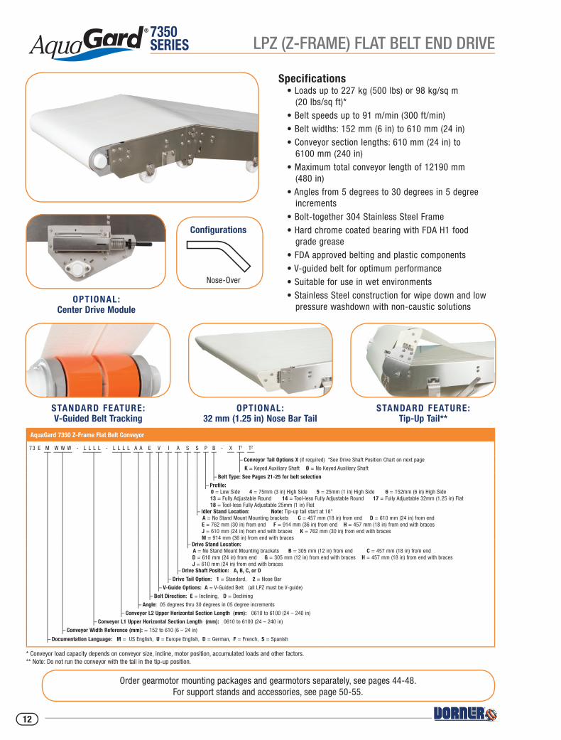
Specifications• Loads up to 227 kg (500 lbs) or 98 kg/sq m (20 lbs/sq ft)*• Belt speeds up to 91 m/min (300 ft/min)• Belt widths: 152 mm (6 in) to 610 mm (24 in)• Conveyor section lengths: 610 mm (24 in) to 6100 mm (240 in)• Maximum total conveyor length of 12190 mm (480 in)• Angles from 5 degrees to 30 degrees in 5 degree increments• Bolt-together 304 Stainless Steel Frame• Hard chrome coated bearing with FDA H1 food grade grease• FDA approved belting and plastic components• V-guided belt for optimum performance• Suitable for use in wet environments• Stainless Steel construction for wipe down and low pressure washdown with non-caustic solutions
Order gearmotor mounting packages and gearmotors separately, see pages 44-48.For support stands and accessories, see page 50-55.
* Conveyor load capacity depends on conveyor size, incline, motor position, accumulated loads and other factors.** Note: Do not run the conveyor with the tail in the tip-up position.
AquaGard 7350 Z-Frame Flat Belt Conveyor
73 E M W W W - L L L L - L L L L A A E V I A S S P B - X T1 T2
– Conveyor Tail Options X (if required) *See Drive Shaft Position Chart on next page
K = Keyed Auxiliary Shaft Ø = No Keyed Auxiliary Shaft
– Belt Type: See Pages 21-25 for belt selection
– Profile: 0 = Low Side 4 = 75mm (3 in) High Side 5 = 25mm (1 in) High Side 6 = 152mm (6 in) High Side 13 = Fully Adjustable Round 14 = Tool-less Fully Adjustable Round 17 = Fully Adjustable 32mm (1.25 in) Flat 18 = Tool-less Fully Adjustable 25mm (1 in) Flat
– Idler Stand Location: Note: Tip-up tail start at 18" A = No Stand Mount Mounting brackets C = 457 mm (18 in) from end D = 610 mm (24 in) from end E = 762 mm (30 in) from end F = 914 mm (36 in) from end H = 457 mm (18 in) from end with braces J = 610 mm (24 in) from end with braces K = 762 mm (30 in) from end with braces M = 914 mm (36 in) from end with braces
– Drive Stand Location: A = No Stand Mount Mounting brackets B = 305 mm (12 in) from end C = 457 mm (18 in) from end D = 610 mm (24 in) from end G = 305 mm (12 in) from end with braces H = 457 mm (18 in) from end with braces J = 610 mm (24 in) from end with braces
– Drive Shaft Position: A, B, C, or D
– Drive Tail Option: 1 = Standard, 2 = Nose Bar
– V-Guide Options: A = V-Guided Belt (all LPZ must be V-guide)
– Belt Direction: E = Inclining, D = Declining
– Angle: 05 degrees thru 30 degrees in 05 degree increments
– Conveyor L2 Upper Horizontal Section Length (mm): 0610 to 6100 (24 – 240 in)
– Conveyor L1 Upper Horizontal Section Length (mm): 0610 to 6100 (24 – 240 in)
– Conveyor Width Reference (mm): = 152 to 610 (6 – 24 in)
– Documentation Language: M = US English, U = Europe English, D = German, F = French, S = Spanish
OPTIONAL: Center Drive Module
STANDARD FEATURE: V-Guided Belt Tracking
OPTIONAL: 32 mm (1.25 in) Nose Bar Tail
STANDARD FEATURE:Tip-Up Tail**
Configurations
Nose-Over
LPZ (Z-FRAME) FLAT BELT END DRIVE
12
7350SERIES
W =
Con
veyo
r Bel
t Wid
th
Dim
= m
m (i
n)Dr
ive
Shaf
t Pos
ition
Sinc
e be
lts a
re b
eing
pul
led,
pos
ition
s A
& D
are
pref
erre
d. P
ushi
ng b
elts
(B &
C) r
educ
es c
onve
yor
load
cap
acity
by
appr
oxim
atel
y 66
%.
STA
NDAR
D SI
ZES
Conv
eyor
Wid
th R
efer
ence
152
203
254
305
356
406
457
508
559
610
Conv
eyor
Bel
t Wid
th (W
)15
220
325
430
535
640
645
750
855
961
0
(6)
(8)
(10)
(12)
(14)
(16)
(18)
(20)
(22)
(24)
Conv
eyor
Len
gth
Refe
renc
e06
1000
005
incr
emen
ts u
p to
…61
00
Conv
eyor
Len
gth
(L1/
L2/L
3)06
10 (2
4)00
005
(0.2
) inc
rem
ents
up
to…
6100
(240
)
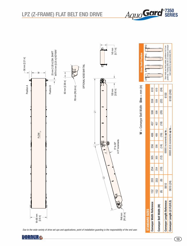
FLOW
25 m
m [1.
00 in
] DIA
. SHA
FTW
ITH 6
mm [0
.25 in
] KEY
WAY
56 m
m [2.
21 in
]
W+6
6 mm
[2.6 i
n]W
100 m
m [3.
92 in
]
L1
5º to
30º
in 5º
incre
ments
R46 m
m [R
1.81 i
n]
145 m
m [5.
71 in
]
OPTIO
NAL N
OSE B
AR TA
IL
60 m
m [2.
38 in
]
R9 m
m [R
0.34 i
n]
Posit
ion A
Posit
ion D
L2
Due to the wide variety of drive set ups and applications, point of installation guarding is the responsibility of the end user.
LPZ (Z-FRAME) FLAT BELT END DRIVE
13
7350SERIES
AquaGard 7350 Z-Frame Cleated Conveyor
73 C M W W W - L L L L - L L L L - L L L L A A E V A D D P B S S S S - X T1 T2
– Conveyor Tail Options X (if required) *See Drive Shaft Position Chart on next page
K = Keyed Auxiliary Shaft Ø = No Keyed Auxiliary Shaft
– Spacing: SSSS in millimeters
– Belt/Cleat Type: See Pages 21-25 for belt selection
– Profile: 0 = Low Side 2 = Cleated 25mm (1 in) Bolt On High Side 3 = Cleated 75mm (3 in) Bolt On High Side 6 = Cleated 152mm (6 in) Bolt on High Side
– Idler Stand Location: Note: Tip-up tail start at 18 in A = No Stand Mount Mounting brackets C = 457 mm (18 in) from end D = 610 mm (24 in) from end E = 762 mm (30 in) from end F = 914 mm (36 in) from end H = 457 mm (18 in) from end with braces J = 610 mm (24 in) from end with braces K = 762 mm (30 in) from end with braces M = 914 mm (36 in) from end with braces
– Drive Stand Location: A = No Stand Mount Mounting brackets B = 305 mm (12 in) from end C = 457 mm (18 in) from end D = 610 mm (24 in) from end G = 305 mm (12 in) from end with braces H = 457 mm (18 in) from end with braces J = 610 mm (24 in) from end with braces
– Drive Shaft Position: A, B, C, or D
– V-Guide Options: A = V-Guided Belt (all LPZ must be V-guide)
– Belt Direction: E = Inclining, D = Declining
– Angle: 30 degrees thru 60 degrees in 05 degree increments
– Conveyor L3 Lower Horizontal Section Length (mm): 0610 - 6100 (24 – 240 in)
– Conveyor L2 Angled Section Length (mm): 0610 - 6100 (24 – 240 in)
– Conveyor L1 Upper Horizontal Section Length (mm): 0610 - 6100 (24 – 240 in)
– Conveyor Width Reference (mm): = 152 to 610 (6 – 24 in)
– Documentation Language: M = US English, U = Europe English, D = German, F = French, S = Spanish
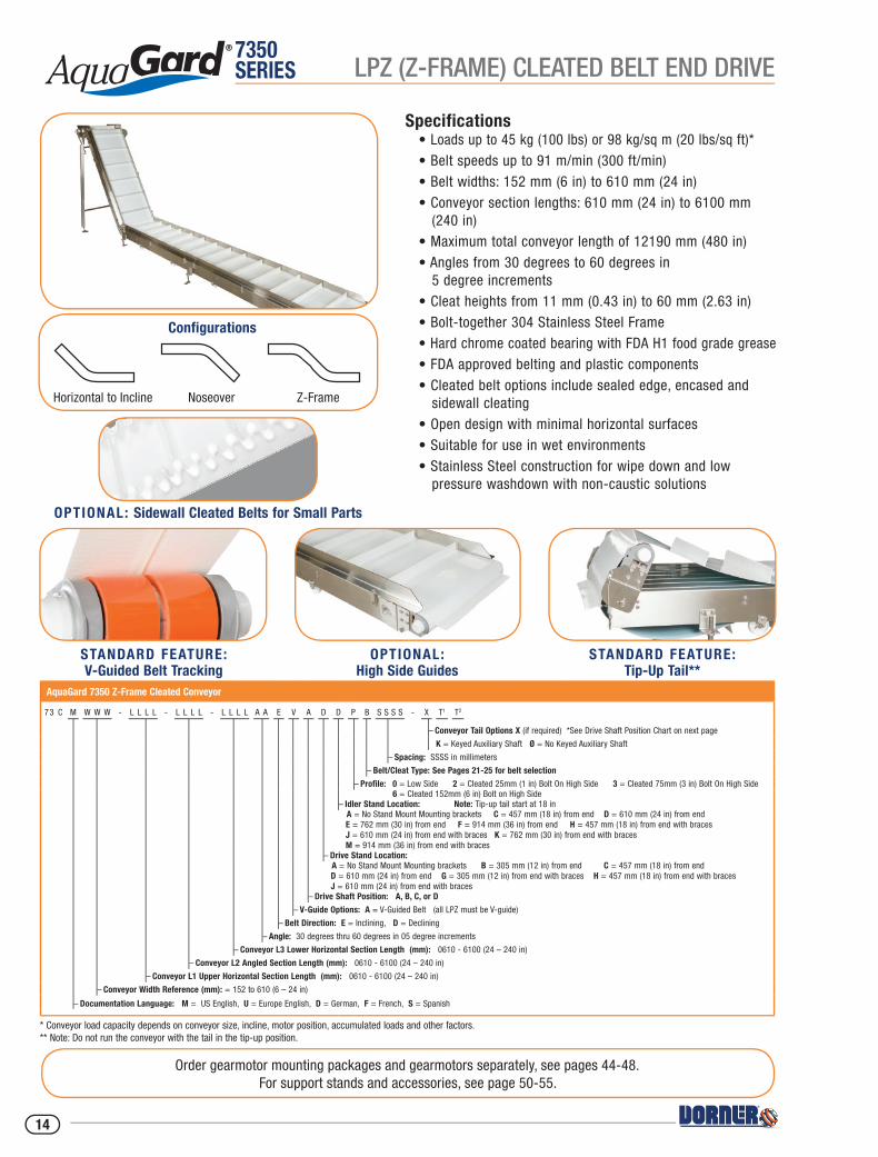
Specifications• Loads up to 45 kg (100 lbs) or 98 kg/sq m (20 lbs/sq ft)*• Belt speeds up to 91 m/min (300 ft/min)• Belt widths: 152 mm (6 in) to 610 mm (24 in)• Conveyor section lengths: 610 mm (24 in) to 6100 mm (240 in)• Maximum total conveyor length of 12190 mm (480 in)• Angles from 30 degrees to 60 degrees in 5 degree increments• Cleat heights from 11 mm (0.43 in) to 60 mm (2.63 in)• Bolt-together 304 Stainless Steel Frame• Hard chrome coated bearing with FDA H1 food grade grease• FDA approved belting and plastic components• Cleated belt options include sealed edge, encased and sidewall cleating• Open design with minimal horizontal surfaces• Suitable for use in wet environments• Stainless Steel construction for wipe down and low pressure washdown with non-caustic solutions
Order gearmotor mounting packages and gearmotors separately, see pages 44-48.For support stands and accessories, see page 50-55.
* Conveyor load capacity depends on conveyor size, incline, motor position, accumulated loads and other factors.** Note: Do not run the conveyor with the tail in the tip-up position.
OPTIONAL: Sidewall Cleated Belts for Small Parts
STANDARD FEATURE: V-Guided Belt Tracking
OPTIONAL: High Side Guides
STANDARD FEATURE:Tip-Up Tail**
Configurations
Horizontal to Incline Noseover Z-Frame
LPZ (Z-FRAME) CLEATED BELT END DRIVE
14
7350SERIES
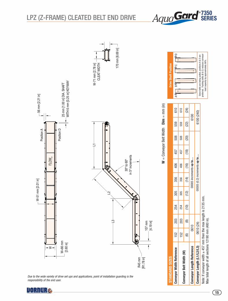
W =
Con
veyo
r Bel
t Wid
th
Dim
= m
m (i
n)
Driv
e Sh
aft P
ositi
on
Sinc
e be
lts a
re b
eing
pul
led,
pos
ition
s A
& D
are
pref
erre
d. P
ushi
ng b
elts
(B &
C) r
educ
es c
onve
yor
load
cap
acity
by
appr
oxim
atel
y 66
%.
STA
NDAR
D SI
ZES
Conv
eyor
Wid
th R
efer
ence
152
203
254
305
356
406
457
508
559
610
Conv
eyor
Bel
t Wid
th (W
)15
220
325
430
535
640
645
750
855
961
0
(6)
(8)
(10)
(12)
(14)
(16)
(18)
(20)
(22)
(24)
Conv
eyor
Len
gth
Refe
renc
e06
1000
005
incr
emen
ts u
p to
…61
00
Conv
eyor
Len
gth
(L1/
L2/L
3)06
10 (2
4)00
005
(0.2
) inc
rem
ents
up
to…
6100
(240
)
Note
: If c
onve
yor w
idth
≥ 4
57 m
m th
en th
e m
ax le
ngth
is 2
135
mm
. M
ax to
tal l
engt
h of
all
sect
ions
121
90 m
m (4
80 in
).
FLOW
Posit
ion A
Posit
ion D
25 m
m [1.
00 in
] DIA
. SHA
FTW
ITH 6
mm [0
.25 in
] KEY
WAY
56 m
m [2.
21 in
]W
-51 m
m [2.
01 in
]
W
W+6
6 mm
[2.60
in]
L1
L2L3
30º t
o 60º
in 5º
incre
ments
107 m
m [4.
19 in
]
R45 m
m [R
1.78 i
n]
W-7
1 mm
[2.78
in]
CLEA
T WID
TH 170 m
m [6.
69 in
]
Due to the wide variety of drive set ups and applications, point of installation guarding is the responsibility of the end user.
LPZ (Z-FRAME) CLEATED BELT END DRIVE
15
7350SERIES
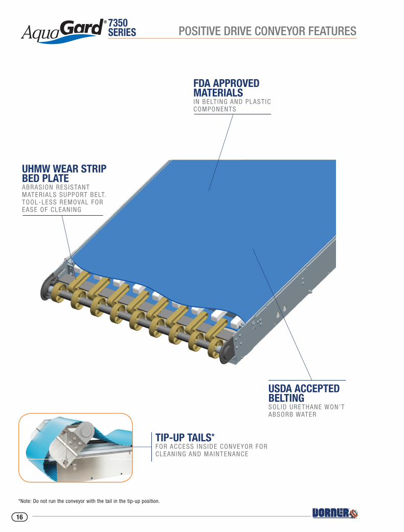
*Note: Do not run the conveyor with the tail in the tip-up position.
TIP-UP TAILS* FOR ACCESS INS IDE CONVEYOR FOR CLEANING AND MAINTENANCE
POSITIVE DRIVE CONVEYOR FEATURES
USDA ACCEPTED BELTINGSOLID URETHANE WON'T ABSORB WATER
FDA APPROVED MATERIALSIN BELT ING AND PLASTIC COMPONENTS
UHMW WEAR STRIP BED PLATEABRASION RESISTANT MATERIALS SUPPORT BELT.TOOL-LESS REMOVAL FOR EASE OF CLEANING
16
7350SERIES
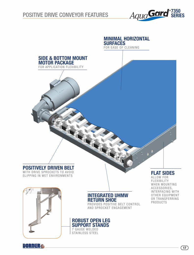
ROBUST OPEN LEG SUPPORT STANDS 7 GAUGE WELDED STAINLESS STEEL
POSITIVE DRIVE CONVEYOR FEATURES
SIDE & BOTTOM MOUNT MOTOR PACKAGE FOR APPL ICATION FLEX IB IL ITY
POSITIVELY DRIVEN BELT WITH DRIVE SPROCKETS TO AVOID SL IPP ING IN WET ENVIRONMENTS
FLAT SIDES ALLOW FOR FLEXIB IL ITY WHEN MOUNTING ACCESSORIES, INTERFACING WITH OTHER EQUIPMENT OR TRANSFERRING PRODUCTS
MINIMAL HORIZONTAL SURFACES FOR EASE OF CLEANING
INTEGRATED UHMW RETURN SHOEPROVIDES POSIT IVE BELT CONTROL AND SPROCKET ENGAGEMENT
17
7350SERIES
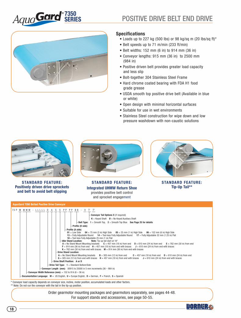
Specifications• Loads up to 227 kg (500 lbs) or 98 kg/sq m (20 lbs/sq ft)*• Belt speeds up to 71 m/min (233 ft/min)• Belt widths: 152 mm (6 in) to 914 mm (36 in)• Conveyor lengths: 915 mm (36 in) to 2500 mm (984 in)• Positive driven belt provides greater load capacity and less slip• Bolt-together 304 Stainless Steel Frame• Hard chrome coated bearing with FDA H1 food grade grease• USDA smooth top positive drive belt (Available in blue or white)• Open design with minimal horizontal surfaces• Suitable for use in wet environments• Stainless Steel construction for wipe down and low pressure washdown with non-caustic solutions
AquaGard 7350 Belted Positive Drive Conveyor
73 P M W W W - L L L L L D A S S P P P P B B - X T1 T2
– Conveyor Tail Options X (if required)
K = Keyed Shaft Ø = No Keyed Auxiliary Shaft
– Belt Type: 1 = Smooth Top, 2 = Smooth Top Blue See Page 25 for details
– Profile (D side)
– Profile (A side) 01 = Low Side 04 = 75 mm (3 in) High Side 05 = 25 mm (1 in) High Side 06 = 152 mm (6 in) High Side 13 = Fully Adjustable Round 14 = Tool-less Fully Adjustable Round 17 = Fully Adjustable 32 mm (1.25 in) Flat 18 = Tool-less Fully Adjustable 25 mm (1 in) Flat
– Idler Stand Location: Note: Tip-up tail start at 18" A = No Stand Mount Mounting brackets C = 457 mm (18 in) from end D = 610 mm (24 in) from end E = 762 mm (30 in) from end F = 914 mm (36 in) from end H = 457 mm (18 in) from end with braces J = 610 mm (24 in) from end with braces K = 762 mm (30 in) from end with braces M = 914 mm (36 in) from end with braces
– Drive Stand Location: A = No Stand Mount Mounting brackets B = 305 mm (12 in) from end C = 457 mm (18 in) from end D = 610 mm (24 in) from end G = 305 mm (12 in) from end with braces H = 457 mm (18 in) from end with braces J = 610 mm (24 in) from end with braces
– Drive Shaft Position: A or D
– Drive Tail Type: 1 = Standard Bottom/Side
– Conveyor Length (mm): 00915 to 25000 in 5 mm increments (36 – 984 in)
– Conveyor Width Reference (mm): = 152 to 914 (6 – 36 in)
– Documentation Language: M = US English, U = Europe English, D = German, F = French, S = Spanish
Order gearmotor mounting packages and gearmotors separately, see pages 44-48.For support stands and accessories, see page 50-55.
* Conveyor load capacity depends on conveyor size, incline, motor position, accumulated loads and other factors.** Note: Do not run the conveyor with the tail in the tip-up position.
STANDARD FEATURE:Integrated UHMW Return Shoe
provides positive belt control and sprocket engagement
STANDARD FEATURE:Positively driven drive sprockets
and belt to avoid belt slipping
STANDARD FEATURE:Tip-Up Tail**
POSITIVE DRIVE BELT END DRIVE
18
7350SERIES
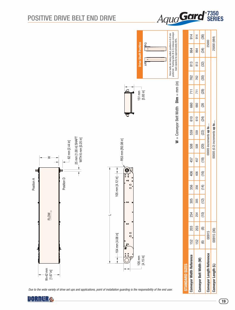
W =
Con
veyo
r Bel
t Wid
th
Dim
= m
m (i
n)
Driv
e Sh
aft P
ositi
on
Sinc
e be
lts a
re b
eing
pul
led,
pos
ition
s A
& D
are
pref
erre
d. P
ushi
ng b
elts
(B &
C) r
educ
es c
onve
yor
load
cap
acity
by
appr
oxim
atel
y 66
%.
STA
NDAR
D SI
ZES
Conv
eyor
Wid
th R
efer
ence
152
203
254
305
356
406
457
508
559
610
660
711
762
813
864
914
Conv
eyor
Bel
t Wid
th (W
)15
220
325
430
535
640
645
750
855
961
066
071
176
281
386
491
4
(6)
(8)
(10)
(12)
(14)
(16)
(18)
(20)
(22)
(24)
(26
(28)
(30)
(32)
(34)
(36)
Conv
eyor
Len
gth
Refe
renc
e00
915
0000
5 in
crem
ents
up
to…
2500
0
Conv
eyor
Len
gth
(L)
0091
5 (3
6)00
005
(0.2
) inc
rem
ents
up
to…
2500
0 (9
84)
25 m
m [1.
00 in
] SHA
FTW
ITH 6
mm [0
.25 in
]
W
Posit
ion A
Posit
ion D
FLOW
W+4
2 mm
[1.67
in]
62 m
m [2.
44 in
]
L
R53 m
m [R
2.08 i
n]
105 m
m [4.
15 in
]
104 m
m [4.
08 in
]
151 m
m [5.
93 in
]
105 m
m [4.
12 in
]
Due to the wide variety of drive set ups and applications, point of installation guarding is the responsibility of the end user.
POSITIVE DRIVE BELT END DRIVE
19
7350SERIES
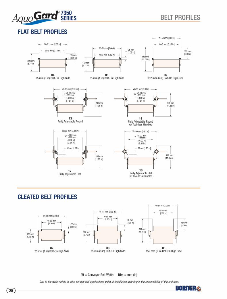
06152 mm (6 in) Bolt-On High Side
0475 mm (3 in) Bolt-On High Side
0525 mm (1 in) Bolt-On High Side
223 mm [8.77 in]
W+51 mm [2.00 in]
W+3 mm [0.12 in]
78 mm [3.09 in]
172 mm [6.77 in]
W+51 mm [2.00 in]
W+3 mm [0.12 in]
28 mm [1.09 in]
299 mm [11.77 in]
W+51 mm [2.00 in]
W+3 mm [0.12 in]
155 mm [6.09 in]
W+99 mm [3.91 in.]
288 mm [11.35 in]
W+99 mm [3.91 in.
288 mm [11.35 in]
W +0.00 mm-199 mm
[+0.00 in][-7.84 in]
32mm [1.25 in]
288 mm [11.35 in]
288 mm [11.35 in]
32mm [1.25 in]
W +0.00 mm-199 mm[+0.00 in][-7.84 in]
W+99 mm [3.91 in] W+99 mm [3.91 in]
W +0.00 mm-199 mm[+0.00 in][-7.84 in]
W +0.00 mm-199 mm[+0.00 in][-7.84 in]
13Fully Adjustable Round
14Fully Adjustable Roundw/ Tool-less Handles
17Fully Adjustable Flat
18Fully Adjustable Flatw/ Tool-less Handles
0225 mm (1 in) Bolt-On High Side
0375 mm (3 in) Bolt-On High Side
06152 mm (6 in) Bolt-On High Side
172 mm [6.76 in]
W+51 mm [2.00 in]
W-58 mm[2.30 in] 27 mm
[1.08 in]
222 mm [8.76 in]
W+51 mm [2.00 in]
W-58 mm[2.30 in] 78 mm
[3.08 in]
299 mm [11.76 in]
W+51 mm [2.00 in]
W-58 mm[2.30 in]
154 mm [6.08 in]
BELT PROFILES
Due to the wide variety of drive set ups and applications, point of installation guarding is the responsibility of the end user.
W = Conveyor Belt Width Dim = mm (in)
FLAT BELT PROFILES
CLEATED BELT PROFILES
20
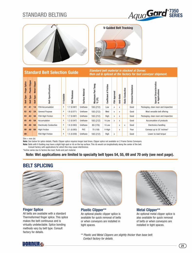
7350SERIESSTANDARD BELTING
BELT SPLICING
Plastic Clipper**An optional plastic clipper splice is available for quick removal of belts or when conveyors are installed in tight spaces.
Finger SpliceAll belts are available with a standard Thermoformed finger splice. This splice makes the belt continuous and is virtually undetectable. Splice bonding methods vary by belt type. Consult factory for details.
Metal Clipper**An optional metal clipper splice is also available for quick removal of belts or when conveyors are installed in tight spaces.
** Plastic and Metal Clippers are slightly thicker than base belt. Contact factory for details.
V-Guided Belt Tracking
Standard Belt Selection Guide Standard belt material is stocked at Dorner, then cut & spliced at the factory for fast conveyor shipment.
Belt
Type
- F
inge
r Sp
lice
Belt
Type
- P
last
ic C
lippe
r
Belt
Type
- M
etal
Clip
per
Bel
t Sp
ecif
icat
ions
V-Gu
idab
le
Belt
Thic
knes
s
Surf
ace
Mat
eria
l
Max
imum
Par
t Tem
p.
ºC (º
F)
Coef
ficie
nt o
f Fric
tion
FDA
Appr
oved
Anti-
Stat
ic
Stat
ic C
ondu
ctiv
e
Chem
ical
Res
ista
nce
Spec
ial C
hara
cter
istic
sor
App
licat
ions
01 A1 1A FDA Accumulation x 1.7 (0.067) Urethane 100 (212) Low x x Good Packaging, clean room and inspection
02 A2 2A General Purpose x 1.8 (0.071) Urethane 100 (212) Med x x Good Most versatile belt offering
03 A3 3A FDA High Friction x 1.7 (0.067) Urethane 100 (212) High x x Good Packaging, clean room and inspection
05 A5 5A Accumulation x 1.2 (0.047) Urethane 100 (212) V-Low x x Good Accumulation of products
06 A6 6A Electrically Conductive x 1.6 (0.063) Urethane 80 (176) V-Low x x Good Electronics handling
08 A8 8A High Friction x 2.1 (0.083) PVC 70 (158) V-High x Poor Conveys up to 35˚ inclines*
09 FDA High Friction x 1.5 (0.059) Urethane 100 (212) High x Good Lower no load torque
Dim = mm (in)Note: See below for splice details. Plastic Clipper splice requires longer lead times. Clipper splice not available on Z-Frame Series Conveyors.Note: Belts with V-Guiding may have a slight high spot or rib on the top surface. This rib would run longitudinally along the center of the belt.
Consult factory with applications for which this may cause interference.*Incline varies due to factors like dust, fluids and part material.
Note: Wet applications are limited to specialty belt types 54, 55, 69 and 70 only (see next page).
21

7350SERIES SPECIALTY BELTING
Specialty Belt Selection Guide Specialty belt material is not stocked at Dorner and needs to be custom ordered for your special conveyor needs.
Belt
Type
- F
inge
r Sp
lice
Belt
Type
- P
last
ic C
lippe
r
Belt
Type
- M
etal
Clip
per*
*
Belt
Spec
ifica
tions
Belt
Thic
knes
s
Surf
ace
Mat
eria
l
Max
imum
Par
t Tem
p. ºC
(ºF)
Coef
ficie
nt o
f Fric
tion
FDA
Appr
oved
Chem
ical
Res
ista
nce
Moi
stur
e Re
sist
ance
Spec
ial C
hara
cter
istic
sor
App
licat
ions
54 F4 4F FDA Sealed Edge 1.5 (0.06) Urethane 80 (176) Low x Good GoodPackaging, clean room & inspection,
wet environment
55 F5 5F FDA Sealed Edge 1.5 (0.06) Urethane 80 (176) High x Good GoodPackaging, clean room & inspection,
wet environment
56 6F Cut Resistant 2.1 (0.08) Urethane 100 (212) Med. Good Poor Oily product release, Metal stamping
57 7F Cut Resistant 2.5 (0.10) Nitrile 80 (176) Med. Poor PoorFelt-like, dry metal stamping, glass &
ceramic
59 F9 9F Color Contrasting 1.5 (0.06) PVC 70 (158) Med. Poor Poor Black colored, hides overspray from ink jet
60 G0 0G Color Contrasting 1.2 (0.05) Urethane 100 (212) Low x Good Poor Green colored, Nose Bar
61 G1 1G Color Contrasting 1.2 (0.05) Urethane 100 (212) Low x Good Poor Blue colored, Nose Bar
63 3G Electrically Conductive 1.2 (0.05) Urethane 60 (140) Low Good Poor Static conductive, electronics handling
64 4G High Friction 4.4 (0.17) PVC 90 (194) V-High Poor PoorDark Green colored, rough top surface,
product cushioning, incline / decline apps
66 6G Chemical Resistant 1.7 (0.07) Polyester 100 (212) Med. x V-Good Poor Good Cut resistance, metal stamping apps
67 7G Low Friction Cleated 1.6 (0.06) Polyester 100 (212) n/a x Good PoorExcellent product release, consult factory for part number and how to specify low
friction
68 G8 FDA Encased* 2.0 (0.08) Urethane 100 (212) Low x Good V-GoodUrethane Enclosed for added sanitary
protection
69 G9 FDA Encased* 2.0 (0.08) Urethane 100 (212) High x Good V-GoodUrethane Enclosed for added sanitary
protection
70 Solid Urethane 2.5 (0.10) Urethane 100 (212) Med. x Good V-Good USDA Approved, wet applications
71 High Release Cover 1.7 (0.07) Urethane 100 (212) Low x Good Poor Raw dough or sticky food product
72 Nose Bar Low Friction 1.2 (0.05) Urethane 100 (212) Low x Good Poor Nose Bar Applications
Dim = mm (in)Metal Clipper Splices are not available on belts over 1219 mm (48 in) wide.* Not available in 51 mm (2 in) wide. **Metal Clipper splices are not sanitary.
Solid Urethane belt for added sanitary protection – See belt type 70 below
High Release Cover belt for handling sticky food such as raw dough – See belt type 71 below
Note: Wet applications are limited to specialty belt types 54, 55, 69 and 70 only.
22
7350SERIESSTANDARD CLEATED BELTING
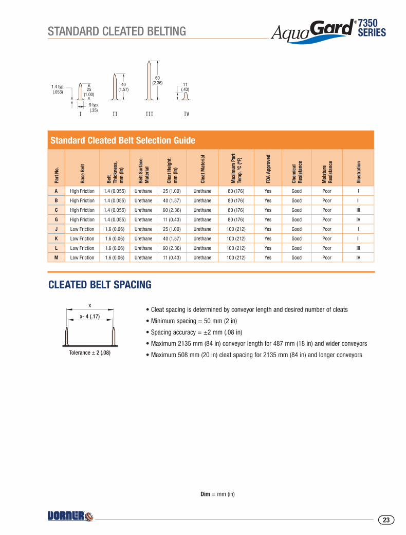
• Cleat spacing is determined by conveyor length and desired number of cleats
• Minimum spacing = 50 mm (2 in)
• Spacing accuracy = ±2 mm (.08 in)
• Maximum 2135 mm (84 in) conveyor length for 487 mm (18 in) and wider conveyors
• Maximum 508 mm (20 in) cleat spacing for 2135 mm (84 in) and longer conveyors
IVIIIIII
IIIIII
III10.50 (0.41)
3.30 (0.13) TYP.
30.00 (1.18)
50.00 (1.97)
10.50 (0.41)
5.50 (0.22) TYP.
20 (0.79) 60(2.36)
40 (1.57)
DOC0989
1.4 typ.(.053)
9 typ.(.35)
25(1.00)
40(1.57)
60(2.36) 11
(.43)
Standard Cleated Belt Selection Guide
Part
No.
Base
Bel
t
Belt
Thic
knes
s,
mm
(in)
Belt
Surf
ace
Mat
eria
l
Clea
t Hei
ght,
mm
(in)
Clea
t Mat
eria
l
Max
imum
Par
t Te
mp.
ºC (º
F)
FDA
Appr
oved
Chem
ical
Re
sist
ance
Moi
stur
e Re
sist
ance
Illus
trat
ion
A High Friction 1.4 (0.055) Urethane 25 (1.00) Urethane 80 (176) Yes Good Poor I
B High Friction 1.4 (0.055) Urethane 40 (1.57) Urethane 80 (176) Yes Good Poor II
C High Friction 1.4 (0.055) Urethane 60 (2.36) Urethane 80 (176) Yes Good Poor III
G High Friction 1.4 (0.055) Urethane 11 (0.43) Urethane 80 (176) Yes Good Poor IV
J Low Friction 1.6 (0.06) Urethane 25 (1.00) Urethane 100 (212) Yes Good Poor I
K Low Friction 1.6 (0.06) Urethane 40 (1.57) Urethane 100 (212) Yes Good Poor II
L Low Friction 1.6 (0.06) Urethane 60 (2.36) Urethane 100 (212) Yes Good Poor III
M Low Friction 1.6 (0.06) Urethane 11 (0.43) Urethane 100 (212) Yes Good Poor IV
x
x- 4 (.17)
Tolerance ± 2 (.08)
CLEATED BELT SPACING
Dim = mm (in)
23
7350SERIES SPECIALTY CLEATED BELTING
Specialty Cleated Belt Selection Guide
Part
No.
Base
Bel
t
Belt
Thic
knes
s,
mm
(in)
Belt
Surf
ace
Mat
eria
l
Clea
t Hei
ght,
mm
(in)
Clea
t Mat
eria
l
Max
imum
Par
t Te
mp.
ºC (º
F)
FDA
Appr
oved
Chem
ical
Re
sist
ance
Moi
stur
e Re
sist
ance
Illus
trat
ion
Clea
ted
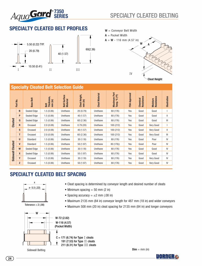
N Sealed Edge 1.5 (0.06) Urethane 20 (0.79) Urethane 80 (176) Yes Good Good I
P Sealed Edge 1.5 (0.06) Urethane 40 (1.57) Urethane 80 (176) Yes Good Good II
Q Sealed Edge 1.5 (0.06) Urethane 60 (2.36) Urethane 80 (176) Yes Good Good III
R Encased 2.0 (0.08) Urethane 0.79 (20) Urethane 100 (212) Yes Good Very Good I
S Encased 2.0 (0.08) Urethane 40 (1.57) Urethane 100 (212) Yes Good Very Good II
T Encased 2.0 (0.08) Urethane 60 (2.36) Urethane 100 (212) Yes Good Very Good III
Side
wal
l Cle
ated
U Standard 1.5 (0.06) Urethane 30 (1.18) Urethane 80 (176) Yes Good Poor IV
V Standard 1.5 (0.06) Urethane 50 (1.97) Urethane 80 (176)) Yes Good Poor IV
W Sealed Edge 1.5 (0.06) Urethane 30 (1.18) Urethane 80 (176) Yes Good Good IV
X Sealed Edge 1.5 (0.06) Urethane 50 (1.97) Urethane 80 (176) Yes Good Good IV
Y Encased 1.5 (0.06) Urethane 30 (1.18) Urethane 80 (176) Yes Good Very Good IV
Z Encased 1.5 (0.06) Urethane 50 (1.97) Urethane 80 (176) Yes Good Very Good IV
W A
Cleat Height
IV
W = Conveyor Belt Width
A = Pocket Width
A = W - 116 mm (4.57 in)
IVIIIIII
IIIIII
III10.50 (0.41)
3.30 (0.13) TYP.
30.00 (1.18)
50.00 (1.97)
10.50 (0.41)
5.50 (0.22) TYP.
20 (0.79) 60(2.36)
40 (1.57)
DOC0989
1.4 typ.(.053)
9 typ.(.35)
25(1.00)
40(1.57)
60(2.36) 11
(.43)
x
x- 5.5 (.22)
Tolerance ± 2 (.08)
W-116 (4.57)(Pocket Width)
W
W-72 (2.82)
DOC0988
W+1.77 (45mm)
7.16 (182mm)
Profile for Cleat Type I
W+1.70 (43mm)
W-2.55 (65mm)Pocket Width
W+1.77 (45mm)
8.66 (220mm)
Profile for Cleat Types II & III
C = 171 (6.74) for Type I cleats191 (7.53) for Type II cleats211 (8.31) for Type III cleats
SPECIALTY CLEATED BELT SPACING
SPECIALTY CLEATED BELT PROFILES
Dim = mm (in)
• Cleat spacing is determined by conveyor length and desired number of cleats
• Minimum spacing = 50 mm (2 in)
• Spacing accuracy = ±2 mm (.08 in)
• Maximum 2135 mm (84 in) conveyor length for 487 mm (18 in) and wider conveyors
• Maximum 508 mm (20 in) cleat spacing for 2135 mm (84 in) and longer conveyors
Sidewall Belting
24
7350SERIES
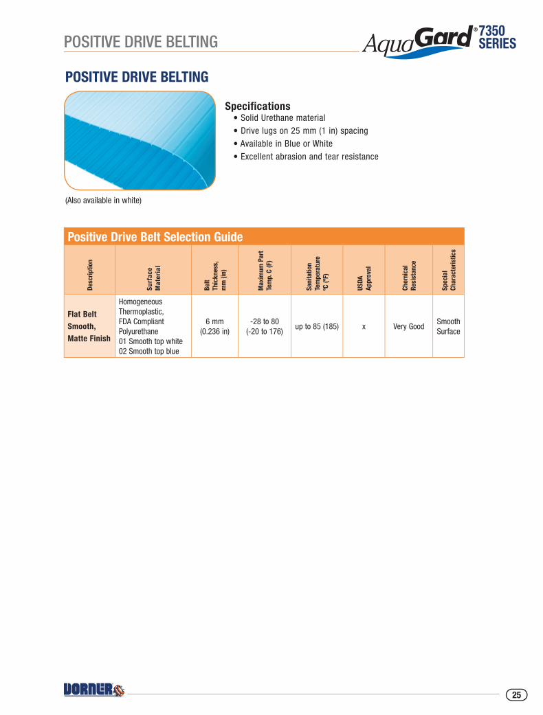
Specifications• Solid Urethane material• Drive lugs on 25 mm (1 in) spacing• Available in Blue or White• Excellent abrasion and tear resistance
POSITIVE DRIVE BELTING
POSITIVE DRIVE BELTING
(Also available in white)
Positive Drive Belt Selection Guide
Desc
riptio
n
Surf
ace
Mat
eria
l
Belt
Thic
knes
s,
mm
(in)
Max
imum
Par
t Te
mp.
C (F
)
Sani
tatio
n Te
mpe
ratu
reºC
(ºF)
USDA
Appr
oval
Chem
ical
Re
sist
ance
Spec
ial
Char
acte
ristic
s
Flat Belt Smooth, Matte Finish
HomogeneousThermoplastic,FDA CompliantPolyurethane01 Smooth top white02 Smooth top blue
6 mm(0.236 in)
-28 to 80(-20 to 176)
up to 85 (185) x Very GoodSmooth Surface
25
7350SERIES
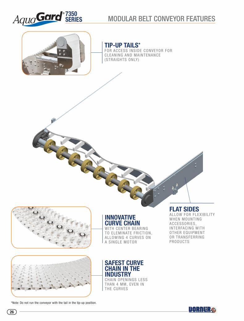
TIP-UP TAILS* FOR ACCESS INS IDE CONVEYOR FOR CLEANING AND MAINTENANCE(STRAIGHTS ONLY)
INNOVATIVE CURVE CHAIN WITH CENTER BEARING TO ELEMINATE FR ICT ION, ALLOWING 4 CURVES ON A S INGLE MOTOR
SAFEST CURVE CHAIN IN THE INDUSTRY CHAIN OPENINGS LESS THAN 4 MM, EVEN IN THE CURVES
*Note: Do not run the conveyor with the tail in the tip-up position.
MODULAR BELT CONVEYOR FEATURES
FLAT SIDES ALLOW FOR FLEXIB IL ITY WHEN MOUNTING ACCESSORIES, INTERFACING WITH OTHER EQUIPMENT OR TRANSFERRING PRODUCTS
26

7350SERIES
COMPACT CURVE FOOTPRINTWITH INFEED AND OUTFEED SECTIONS AS SHORT AS 457 MM (18 IN )
MICROPITCH POWERED TRANSFER FOR END TRANSFER OF PRODUCT AS SMALL AS 75 MM (3 IN ) LONG
ROBUST OPEN LEG SUPPORT STANDS 7 GAUGE WELDED STAINLESS STEEL
MODULAR BELT CONVEYOR FEATURES
MINIMAL HORIZONTAL SURFACES FOR EASY TO CLEAN SANITARY SURFACES
SIDE & BOTTOM MOUNT MOTOR PACKAGE FOR APPL ICATION FLEX IB IL ITY
27
7350SERIES
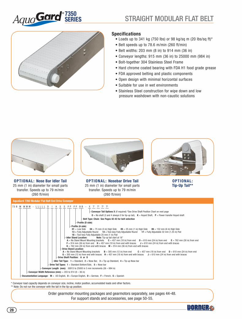
Specifications• Loads up to 341 kg (750 lbs) or 98 kg/sq m (20 lbs/sq ft)*• Belt speeds up to 78.6 m/min (260 ft/min)• Belt widths: 203 mm (8 in) to 914 mm (36 in)• Conveyor lengths: 915 mm (36 in) to 25000 mm (984 in)• Bolt-together 304 Stainless Steel Frame• Hard chrome coated bearing with FDA H1 food grade grease• FDA approved belting and plastic components• Open design with minimal horizontal surfaces• Suitable for use in wet environments• Stainless Steel construction for wipe down and low pressure washdown with non-caustic solutions
Order gearmotor mounting packages and gearmotors separately, see pages 44-48.For support stands and accessories, see page 50-55.
AquaGard 7350 Modular Flat Belt End Drive Conveyor
73 B M W W W - L L L L L D I A S S P P P P B B - X T1 T2 T3 T4
– Conveyor Tail Options X (if required) *See Drive Shaft Position Chart on next page
O = No shaft (3 and 4 always 0 for tip-up tail), K = Keyed Shaft, P = Power transfer Keyed shaft
– Belt Type: Chain See Pages 42-43 for belt selection
– Profile (D side)
– Profile (A side) 01 = Low Side 04 = 75 mm (3 in) High Side 05 = 25 mm (1 in) High Side 06 = 152 mm (6 in) High Side 13 = Fully Adjustable Round 14 = Tool-less Fully Adjustable Round 17 = Fully Adjustable 32 mm (1.25 in) Flat 18 = Tool-less Fully Adjustable 25 mm (1 in) Flat
– Idler Stand Location: Note: Tip-up tail start at 18" A = No Stand Mount Mounting brackets C = 457 mm (18 in) from end D = 610 mm (24 in) from end E = 762 mm (30 in) from end F = 914 mm (36 in) from end H = 457 mm (18 in) from end with braces J = 610 mm (24 in) from end with braces K = 762 mm (30 in) from end with braces M = 914 mm (36 in) from end with braces
– Drive Stand Location: A = No Stand Mount Mounting brackets B = 305 mm (12 in) from end C = 457 mm (18 in) from end D = 610 mm (24 in) from end G = 305 mm (12 in) from end with braces H = 457 mm (18 in) from end with braces J = 610 mm (24 in) from end with braces
– Drive Shaft Position: A or D
– Idler Tail Type: 1 = Standard, 2 = Nose Bar, 3 = Tip-up Standard, 4 = Tip-up Nose bar
– Drive Tail Types: 1 = Standard Bottom/Side, 5 = Nose bar
– Conveyor Length (mm): 00915 to 25000 in 5 mm increments (36 – 984 in)
– Conveyor Width Reference (mm): = 203 to 914 (8 – 36 in)
– Documentation Language: M = US English, U = Europe English, D = German, F = French, S = Spanish
* Conveyor load capacity depends on conveyor size, incline, motor position, accumulated loads and other factors.** Note: Do not run the conveyor with the tail in the tip-up position.
OPTIONAL: Nose Bar Idler Tail25 mm (1 in) diameter for small parts
transfer. Speeds up to 79 m/min (260 ft/min)
OPTIONAL: Nosebar Drive Tail25 mm (1 in) diameter for small parts
transfer. Speeds up to 79 m/min (260 ft/min)
OPTIONAL:Tip-Up Tail**
STRAIGHT MODULAR FLAT BELT
28
7350SERIES
DRIV
E SH
AFT
POSI
TION
DIS
CH
AR
GE
INFE
ED
AD
A-S
IDE
D-S
IDE
T 1T 2 T 4
T 3
W =
Con
veyo
r Bel
t Wid
th
Dim
= m
m (i
n)
STA
NDAR
D SI
ZES
Conv
eyor
Wid
th R
efer
ence
203
254
305
356
406
457
508
559
610
660
711
762
813
864
914
Conv
eyor
Bel
t Wid
th (W
)20
325
430
535
640
645
750
855
961
066
071
176
281
386
491
4
(8)
(10)
(12)
(14)
(16)
(18)
(20)
(22)
(24)
(26
(28)
(30)
(32)
(34)
(36)
Conv
eyor
Len
gth
Refe
renc
e00
915
0000
5 in
crem
ents
up
to…
2500
0
Conv
eyor
Len
gth
(L)
0915
(36)
0000
5 (0
.2) i
ncre
men
ts u
p to
…25
000
(984
)
W
55 m
m [2.
15 in
]
W +
27 m
m [1.
08 in
]FL
OW 25 m
m [1.
00 in
] DIA
. SHA
FTW
ITH 6
mm [0
.25 in
] KEY
WAY
L
155 m
m [6.
09 in
]
105 m
m [4.
14 in
]10
6 mm
[4.19
in]
176 m
m [6.
92 in
]
OPTIO
NAL N
OSE B
AR TA
IL
OPTIO
NAL N
OSE B
AR D
RIVE
R26 m
m [R
1.01 i
n]
80 m
m [3.
16 in
]
80 m
m [3.
16 in
]20
4 mm
[8.02
in]
259 m
m [10
.19 in
]
178 m
m [7.
01 in
]
258 m
m [10
.15 in
]
212 m
m [8.
35 in
]
Posit
ion A
Posit
ion D
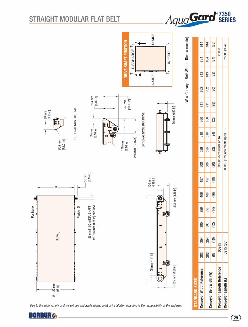
Due to the wide variety of drive set ups and applications, point of installation guarding is the responsibility of the end user.
STRAIGHT MODULAR FLAT BELT
29
7350SERIES
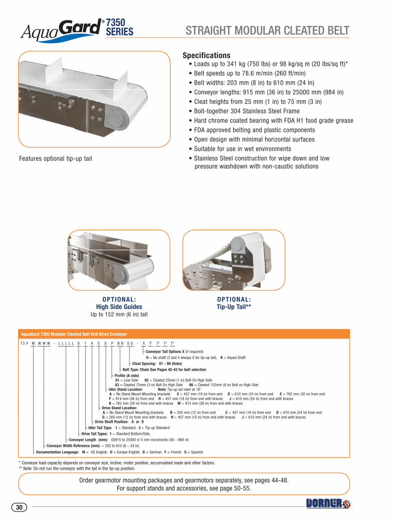
Specifications• Loads up to 341 kg (750 lbs) or 98 kg/sq m (20 lbs/sq ft)*• Belt speeds up to 78.6 m/min (260 ft/min)• Belt widths: 203 mm (8 in) to 610 mm (24 in)• Conveyor lengths: 915 mm (36 in) to 25000 mm (984 in)• Cleat heights from 25 mm (1 in) to 75 mm (3 in) • Bolt-together 304 Stainless Steel Frame• Hard chrome coated bearing with FDA H1 food grade grease• FDA approved belting and plastic components• Open design with minimal horizontal surfaces• Suitable for use in wet environments• Stainless Steel construction for wipe down and low pressure washdown with non-caustic solutions
* Conveyor load capacity depends on conveyor size, incline, motor position, accumulated loads and other factors.** Note: Do not run the conveyor with the tail in the tip-up position.
Order gearmotor mounting packages and gearmotors separately, see pages 44-48.For support stands and accessories, see page 50-55.
AquaGard 7350 Modular Cleated Belt End Drive Conveyor
73 F M W W W - L L L L L D T A S S P B B S S - X T1 T2 T3 T4
– Conveyor Tail Options X (if required)
O = No shaft (3 and 4 always 0 for tip-up tail), K = Keyed Shaft
– Cleat Spacing: 01 - 99 (links)
– Belt Type: Chain See Pages 42-43 for belt selection
– Profile (A side) 01 = Low Side 02 = Cleated 25mm (1 in) Bolt On High Side 03 = Cleated 75mm (3 in) Bolt On High Side 06 = Cleated 152mm (6 in) Bolt on High Side
– Idler Stand Location: Note: Tip-up tail start at 18" A = No Stand Mount Mounting brackets C = 457 mm (18 in) from end D = 610 mm (24 in) from end E = 762 mm (30 in) from end F = 914 mm (36 in) from end H = 457 mm (18 in) from end with braces J = 610 mm (24 in) from end with braces K = 762 mm (30 in) from end with braces M = 914 mm (36 in) from end with braces
– Drive Stand Location: A = No Stand Mount Mounting brackets B = 305 mm (12 in) from end C = 457 mm (18 in) from end D = 610 mm (24 in) from end G = 305 mm (12 in) from end with braces H = 457 mm (18 in) from end with braces J = 610 mm (24 in) from end with braces
– Drive Shaft Position: A or D
– Idler Tail Type: 1 = Standard, 3 = Tip-up Standard
– Drive Tail Types: 1 = Standard Bottom/Side,
– Conveyor Length (mm): 00915 to 25000 in 5 mm increments (36 – 984 in)
– Conveyor Width Reference (mm): = 203 to 610 (8 – 34 in)
– Documentation Language: M = US English, U = Europe English, D = German, F = French, S = Spanish
OPTIONAL: High Side Guides
Up to 152 mm (6 in) tall
OPTIONAL:Tip-Up Tail**
Features optional tip-up tail
STRAIGHT MODULAR CLEATED BELT
30
7350SERIES
W =
Con
veyo
r Bel
t Wid
th
Dim
= m
m (i
n)DR
IVE
SHAF
T PO
SITI
ON
DIS
CH
AR
GE
INFE
ED
AD
A-S
IDE
D-S
IDE
T 1T 2 T 4
T 3
STA
NDAR
D SI
ZES
Conv
eyor
Wid
th R
efer
ence
203
254
305
356
406
457
508
559
610
Conv
eyor
Bel
t Wid
th (W
)20
325
430
535
640
645
750
855
961
0
(8)
(10)
(12)
(14)
(16)
(18)
(20)
(22)
(24)
Conv
eyor
Len
gth
Refe
renc
e00
915
0000
5 in
crem
ents
up
to…
2500
0
Conv
eyor
Len
gth
(L)
0915
(36)
0000
5 (0
.2) i
ncre
men
ts u
p to
…25
000
(984
)
W
55 m
m [2.
15 in
]
W +
27 m
m [1.
08 in
]FL
OW
25 m
m [1.
00 in
] DIA
. SHA
FTW
ITH 6
mm [0
.25 in
] KEY
WAY
L
155 m
m [6.
09 in
]105 m
m [4.
14 in
]
W-7
1 mm
[2.81
in]
CLEA
T WID
TH
R53 m
m [R
2.09 i
n]
106 m
m [4.
19 in
]10
5 mm
[4.14
in]
Posit
ion A
Posit
ion D
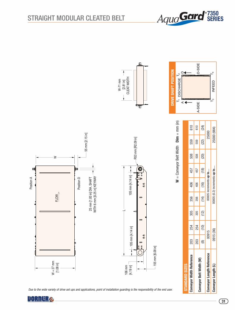
Due to the wide variety of drive set ups and applications, point of installation guarding is the responsibility of the end user.
STRAIGHT MODULAR CLEATED BELT
31

7350SERIES
Specifications• Loads up to 227 kg (500 lbs) or 98 kg/sq m (20 lbs/sq ft)*• Belt speeds up to 78.6 m/min (260 ft/min)• Belt widths: 152 mm (6 in) to 610 mm (24 in)• Conveyor section lengths: 460 mm (18 in) to 15240 mm (600 in)• Curve angles of 45, 90, 135 and 180 degrees• Bolt-together Stainless Steel Frame• Mold to width chain up to 457 mm (18 in) wide• No chain opening exceeding 4 mm (0.15 in)• FDA approved belting and plastic components• Chain supported with stainless steel center bearing, increasing load capacity and the ability to have up to 4 curves on a single motor• Optional powered transfer for smooth transfer of parts as short as 75 mm (3 in) in diameter• Suitable for use in wet environments• Stainless Steel construction for wipe down and low pressure washdown with non-caustic solutions
* Conveyor load capacity depends on conveyor size, incline, motor position, accumulated loads and other factors.
Order gearmotor mounting packages and gearmotors separately, see pages 44-48.For support stands and accessories, see page 50-55.
OPTIONAL: Powered TransferFor small parts and maintaining speeds
through transfer. Slave driven with speeds up to 78.6 m/min (260 ft/min).
Transfer parts as short as 75 mm (3 in) long.
Curve InnovationIntegrated chain bearing and guide rail eliminates friction
STANDARD FEATURE:Flush Top, Low Side Frame
Multiple Curve Configurations
Single Curve
S-Curve U-Curve Up to 4 Curves
CURVED MODULAR FLAT BELT
32

7350SERIES
W =
Con
veyo
r Bel
t Wid
th
Dim
= m
m (i
n)
Driv
e Sh
aft P
ositi
on S
TAND
ARD
SIZE
S Co
nvey
or W
idth
Ref
eren
ce15
230
545
761
0
Conv
eyor
Bel
t Wid
th (W
)15
230
545
761
0
(6)
(12)
(18)
(24)
Conv
eyor
Len
gth
Refe
renc
e00
460
0000
5 in
crem
ents
up
to…
1524
0
Conv
eyor
Len
gth
(L)
0046
0 (1
8)00
005
(0.2
) inc
rem
ents
up
to…
1524
0 (6
00)
NOTE
: Tot
al le
ngth
of a
ll se
ctio
ns c
anno
t exc
eed
2500
0 m
m (9
84 in
)
Max
imum
of 4
cur
ves
Bel
t Wid
th T
able
Co
nvey
or W
idth
m
m (i
n)In
side
Rad
ius
of B
elt
152
(6)
304
(12)
305
(12)
610
(24)
457
(18)
914
(36)
610
(24)
122
0 (4
8)
FLOW
W62
mm
[2.43
in]
25 m
m [1.
00 in
] DIA
. SHA
FT W
ITH 6
mm [.2
5 in]
KEYW
AY
W +
12 m
m [0.
48 in
]
107 m
m [4.
20 in
]
117 m
m [4.
59 in
]
L 1(M
ODUL
E 1)
L 3 (M
ODUL
E 3)
W +
10 m
m [0.
42 in
]
117 m
m [4.
59 in
]
107 m
m [4.
20 in
]
Posit
ion A
Posit
ion D
Due to the wide variety of drive set ups and applications, point of installation guarding is the responsibility of the end user.
CURVED MODULAR FLAT BELT
33

7350SERIES
AquaGard 7350 Series Curved Modular Belt Conveyor - Curve Module
73 T 2 M W W W - A A A D P P P P B B - S S
– Sequence 01
– Belt Type: Chain (XA = Plain Chain, XB = Friction Insert)
– Profile (D side)
– Profile (A side) 01 = Low Side 04 = 75 mm (3 in) High Side 05 = 25 mm (1 in) High Side 06 = 152 mm (6 in) High Side 13 = Fully Adjustable Round 14 = Tool-less Fully Adjustable Round 17 = Fully Adjustable 32 mm (1.25 in) Flat 18 = Tool-less Fully Adjustable 25 mm (1 in) Flat
– Direction: L = Left Hand Turn R = Right Hand Turn
– Degrees of Turn: = 045, 090, 135 or 180
– Conveyor Width Reference (mm): = 152, 305, 457 or 610 (6, 12, 18 or 24 in)
– Documentation Language: M = US English, U = Europe English, D = German, F = French, S = Spanish– Module Type: 2 = Curve Module
– Conveyor Type: T = Modular Belt Curve
AquaGard 7350 Series Curved Modular Belt Conveyor - Intermediate Module
73 T 3 M W W W - L L L L L B P P P P B B - S S
– Sequence 01
– Belt Type: Chain (XA = Plain Chain, XB = Friction Insert)
– Profile (D side)
– Profile (A side) 01 = Low Side 04 = 75 mm (3 in) High Side 05 = 25 mm (1 in) High Side 06 = 152 mm (6 in) High Side 13 = Fully Adjustable Round 14 = Tool-less Fully Adjustable Round 17 = Fully Adjustable 32 mm (1.25 in) Flat 18 = Tool-less Fully Adjustable 25 mm (1 in) Flat
– Stand Style: A =No Braces, B = Braces
– Conveyor Length (mm): 00610 to 15240 in 5 mm increments
– Conveyor Width Reference (mm): = 152, 305, 457 or 610 (6, 12, 18 or 24 in)
– Documentation Language: M = US English, U = Europe English, D = German, F = French, S = Spanish– Module Type: 3 = Intermediate Module
– Conveyor Type: T = Modular Belt Curve
AquaGard 7350 Series Curved Modular Belt Conveyor - Drive Modular
73 T 5 M W W W - L L L L L D A S P P P P B B - S S
– Sequence 01
– Belt Type: Chain (XA = Plain Chain, XB = Friction Insert)
– Profile (D side)
– Profile (A side) 01 = Low Side 04 = 75 mm (3 in) High Side 05 = 25 mm (1 in) High Side 06 = 152 mm (6 in) High Side 13 = Fully Adjustable Round 14 = Tool-less Fully Adjustable Round 17 = Fully Adjustable 32 mm (1.25 in) Flat 18 = Tool-less Fully Adjustable 25 mm (1 in) Flat
– Drive Stand Location: A = No Stand Mount Mounting brackets B = 305mm (12 in) from end C = 457 mm (18 in) from end D = 610 mm (24 in) from end G = 305 mm (12 in) from end with braces H = 457 mm (18 in) from end with braces J = 610 mm (24 in) from end with braces
– Drive Position: A or D
– Drive Tail Type: N = Standard Idler, P = Powered Transfer D = Double Output Shaft
– Conveyor Length (mm): 00460 to 15240 in 5 mm increments
– Conveyor Width Reference (mm): = 152, 305, 457 or 610 (6, 12, 18 or 24 in)
– Documentation Language: M = US English, U = Europe English, D = German, F = French, S = Spanish– Module Type: 5 = Drive Module
– Conveyor Type: T = Modular Belt Curve
AquaGard 7350 Series Curved Modular Belt Conveyor - Infeed Module
73 T 1 M W W W - L L L L L I S P P P P B B - S S
– Sequence 01
– Belt Type: Chain (XA = Plain Chain, XB = Friction Insert)
– Profile (D side)
– Profile (A side) 01 = Low Side 04 = 75 mm (3 in) High Side 05 = 25 mm (1 in) High Side 06 = 152 mm (6 in) High Side 13 = Fully Adjustable Round 14 = Tool-less Fully Adjustable Round 17 = Fully Adjustable 32 mm (1.25 in) Flat 18 = Tool-less Fully Adjustable 25 mm (1 in) Flat
– Idler Stand Location: A = No Stand Mount Mounting brackets C = 457 mm (18 in) from end D = 610 mm (24 in) from end E = 762 mm (30 in) from end F = 914 mm (36 in) from end G = 305 mm (12 in) from end with braces H = 457 mm (18 in) from end with braces J = 610 mm (24 in) from end with braces K = 762 mm (30 in) from end with braces M = 914 mm (36 in) from end with braces
– Idler Tail Type: N = Standard Idler, T = Power Transfer D side, P = Power Transfer A side A = Output Shaft A side, D = Output Shaft D side
– Conveyor Length (mm): 00460 to 15240 in 5 mm increments
– Conveyor Width Reference (mm): = 152, 305, 457 or 610 (6, 12, 18 or 24 in)
– Documentation Language: M = US English, U = Europe English, D = German, F = French, S = Spanish– Module Type: 1 = Infeed Module
– Conveyor Type: T = Modular Belt Curve
CURVED MODULAR FLAT BELT
34
7350SERIES
W+91 mm [3.60 in]
159 mm [6.24 in]
247 mm [9.74 in]
308 mm [12.11 in]
128 mm [5.03 in] END OF
BELT
POWERED TRANSER
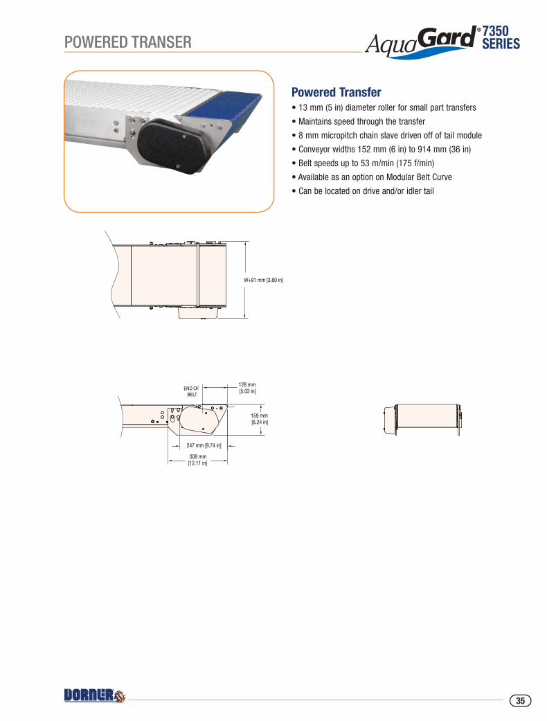
Powered Transfer• 13 mm (5 in) diameter roller for small part transfers
• Maintains speed through the transfer
• 8 mm micropitch chain slave driven off of tail module
• Conveyor widths 152 mm (6 in) to 914 mm (36 in)
• Belt speeds up to 53 m/min (175 f/min)
• Available as an option on Modular Belt Curve
• Can be located on drive and/or idler tail
35
7350SERIES
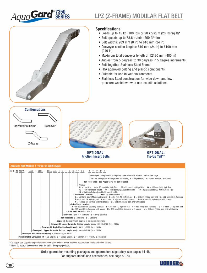
Specifications• Loads up to 45 kg (100 lbs) or 98 kg/sq m (20 lbs/sq ft)*• Belt speeds up to 78.6 m/min (260 ft/min)• Belt widths: 203 mm (8 in) to 610 mm (24 in)• Conveyor section lengths: 610 mm (24 in) to 6100 mm (240 in)• Maximum total conveyor length of 12190 mm (480 in)• Angles from 5 degrees to 30 degrees in 5 degree increments• Bolt-together Stainless Steel Frame• FDA approved belting and plastic components• Suitable for use in wet environments• Stainless Steel construction for wipe down and low pressure washdown with non-caustic solutions
* Conveyor load capacity depends on conveyor size, incline, motor position, accumulated loads and other factors.** Note: Do not run the conveyor with the tail in the tip-up position.
Order gearmotor mounting packages and gearmotors separately, see pages 44-48.For support stands and accessories, see page 50-55.
AquaGard 7350 Modular Z-Frame Flat Belt Conveyor
73 B M WWW - LLLL - LLLL - LLLL A A E D 1 S S P P B B - X T1 T2 T3 T4
– Conveyor Tail Options X (if required) *See Drive Shaft Position Chart on next page
O = No shaft (3 and 4 always 0 for tip-up tail), K = Keyed Shaft, P = Power Transfer Keyed Shaft
– Belt Type: Chain See Pages 42-43 for belt selection
– Profile: 01 = Low Side 04 = 75 mm (3 in) High Side 05 = 25 mm (1 in) High Side 06 = 152 mm (6 in) High Side 13 = Fully Adjustable Round 14 = Tool-less Fully Adjustable Round 17 = Fully Adjustable 32 mm (1.25 in) Flat 18 = Tool-less Fully Adjustable 25 mm (1 in) Flat
– Idler Stand Location: Note: Tip-up tail start at 18" A = No Stand Mount Mounting brackets C = 457 mm (18 in) from end D = 610 mm (24 in) from end E = 762 mm (30 in) from end F = 914 mm (36 in) from end H = 457 mm (18 in) from end with braces J = 610 mm (24 in) from end with braces K = 762 mm (30 in) from end with braces M = 914 mm (36 in) from end with braces
– Drive Stand Location: A = No Stand Mount Mounting brackets B = 305 mm (12 in) from end C = 457 mm (18 in) from end D = 610 mm (24 in) from end G = 305 mm (12 in) from end with braces H = 457 mm (18 in) from end with braces J = 610 mm (24 in) from end with braces
– Drive Shaft Position: A or D
– Drive Tail Type: 1 = Standard, 3 = Tip-up Standard
– Belt Direction: E = Inclining, D = Declining
– Angle: 05 degrees thru 30 degrees in 05 degree increments
– Conveyor L3 Lower Horizontal Section Length (mm): 0610 to 6100 (24 – 240 in)
– Conveyor L2 Angled Section Length (mm): 0610 to 6100 (24 – 240 in)
– Conveyor L1 Upper Horizontal Section Length (mm): 0610 to 6100 (24 – 240 in)
– Conveyor Width Reference (mm): = 203 to 610 (8 – 24 in)
– Documentation Language: M = US English, U = Europe English, D = German, F = French, S = Spanish
OPTIONAL:Friction Insert Belts
OPTIONAL:Tip-Up Tail**
Configurations
Horizontal to Incline Noseover
Z-Frame
LPZ (Z-FRAME) MODULAR FLAT BELT
36
7350SERIES
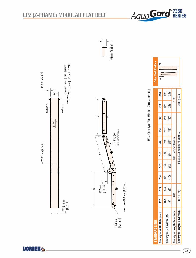
W =
Con
veyo
r Bel
t Wid
th
Dim
= m
m (i
n)
Driv
e Sh
aft P
ositi
on S
TAND
ARD
SIZE
S Co
nvey
or W
idth
Ref
eren
ce15
220
325
430
535
640
645
750
855
961
0
Conv
eyor
Bel
t Wid
th (W
)15
220
325
430
535
640
645
750
855
961
0
(6)
(8)
(10)
(12)
(14)
(16)
(18)
(20)
(22)
(24)
Conv
eyor
Len
gth
Refe
renc
e06
1000
005
incr
emen
ts u
p to
…61
00
Conv
eyor
Len
gth
(L1/
L2/L
3)06
10 (2
4)00
005
(0.2
) inc
rem
ents
up
to…
6100
(240
)W
59 m
m [2.
33 in
]W
-68 m
m [2.
64 in
]Po
sition
A
Posit
ion D
L1L2
L3 157 m
m[6.
18 in
]
106 m
m [4.
16 in
]
5º to
30º
in 5º
incre
ments
158 m
m [6.
23 in
]R5
4 mm
[R2.1
2 in]
W+3
1 mm
[1.21
in]
25 m
m [1.
00 in
] DIA
. SHA
FTW
ITH 6
mm [0
.25 in
] KEY
WAY
FLOW
LPZ (Z-FRAME) MODULAR FLAT BELT
37
7350SERIES
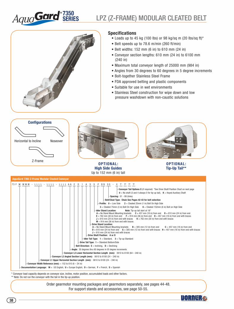
Specifications• Loads up to 45 kg (100 lbs) or 98 kg/sq m (20 lbs/sq ft)*• Belt speeds up to 78.6 m/min (260 ft/min)• Belt widths: 152 mm (6 in) to 610 mm (24 in)• Conveyor section lengths: 610 mm (24 in) to 6100 mm (240 in)• Maximum total conveyor length of 25000 mm (984 in)• Angles from 30 degrees to 60 degrees in 5 degree increments• Bolt-together Stainless Steel Frame• FDA approved belting and plastic components• Suitable for use in wet environments• Stainless Steel construction for wipe down and low pressure washdown with non-caustic solutions
* Conveyor load capacity depends on conveyor size, incline, motor position, accumulated loads and other factors.** Note: Do not run the conveyor with the tail in the tip-up position.
Order gearmotor mounting packages and gearmotors separately, see pages 44-48.For support stands and accessories, see page 50-55.
AquaGard 7350 Z-Frame Modular Cleated Conveyor
73 F M W W W - L L L L - L L L L - L L L L A A E D 1 A S S P B B S S - X T1 T2 T3 T4
– Conveyor Tail Options X (if required) *See Drive Shaft Position Chart on next page
0 = No shaft (3 and 4 always 0 for tip-up tail), K = Keyed Auxiliary Shaft
– Spacing: 01 - 99 (links)
– Belt/Cleat Type: Chain See Pages 42-43 for belt selection
– Profile: 0 = Low Side 2 = Cleated 25mm (1 in) Bolt On High Side
3 = Cleated 75mm (3 in) Bolt On High Side 6 = Cleated 152mm (6 in) Bolt on High Side
– Idler Stand Location: Note: Tip-up tail start at 18" A = No Stand Mount Mounting brackets C = 457 mm (18 in) from end D = 610 mm (24 in) from end E = 762 mm (30 in) from end F = 914 mm (36 in) from end H = 457 mm (18 in) from end with braces J = 610 mm (24 in) from end with braces K = 762 mm (30 in) from end with braces M = 914 mm (36 in) from end with braces
– Drive Stand Location: A = No Stand Mount Mounting brackets B = 305 mm (12 in) from end C = 457 mm (18 in) from end D = 610 mm (24 in) from end G = 305 mm (12 in) from end with braces H = 457 mm (18 in) from end with braces J = 610 mm (24 in) from end with braces
– Drive Shaft Position: A or D
– Idler Tail Type: 1 = Standard, 3 = Tip-up Standard
– Drive Tail Type: 1 = Standard Bottom/Side
– Belt Direction: E = Inclining, D = Declining
– Angle: 30 degrees thru 60 degrees in 05 degree increments
– Conveyor L3 Lower Horizontal Section Length (mm): 0610 to 6100 (64 – 240 in)
– Conveyor L2 Angled Section Length (mm): 0610 to 6100 (24 – 240 in)
– Conveyor L1 Upper Horizontal Section Length (mm): 0610 to 6100 (24 – 240 in)
– Conveyor Width Reference (mm): = 152 to 610 (6 – 24 in)
– Documentation Language: M = US English, U = Europe English, D = German, F = French, S = Spanish
OPTIONAL:Tip-Up Tail**
Configurations
Horizontal to Incline Noseover
Z-FrameOPTIONAL:
High Side GuidesUp to 152 mm (6 in) tall
LPZ (Z-FRAME) MODULAR CLEATED BELT
38

7350SERIES
Driv
e Sh
aft P
ositi
on S
TAND
ARD
SIZE
S Co
nvey
or W
idth
Ref
eren
ce15
220
325
430
535
640
645
750
855
961
0
Conv
eyor
Bel
t Wid
th (W
)15
220
325
430
535
640
645
750
855
961
0
(6)
(8)
(10)
(12)
(14)
(16)
(18)
(20)
(22)
(24)
Conv
eyor
Len
gth
Refe
renc
e06
1000
005
incr
emen
ts u
p to
…61
00
Conv
eyor
Len
gth
(L1/
L2/L
3)06
10 (2
4)00
005
(0.2
) inc
rem
ents
up
to…
6100
(240
)
W =
Con
veyo
r Bel
t Wid
th
Dim
= m
m (i
n)
W
Posit
ion A
Posit
ion D
FLOW
L1
L2L3
30º t
o 60º
, in
5º in
creme
nts
25 m
m [1.
00 in
] DIA
. SHA
FTW
ITH 6
mm [0
.25 in
] KEY
WAY
59 m
m [2.
33 in
]
W+3
1 mm
[1.21
in]
W-6
6 mm
[2.59
in]
106 m
m [4.
18 in
]
W-7
1 mm
[2.81
in]
CLEA
T WID
TH
160 m
m [6.
28 in
]18
4 mm
[7.23
in]
R54 m
m [R
2.14 i
n]
157 m
m [6.
16 in
]
LPZ (Z-FRAME) MODULAR CLEATED BELT
39
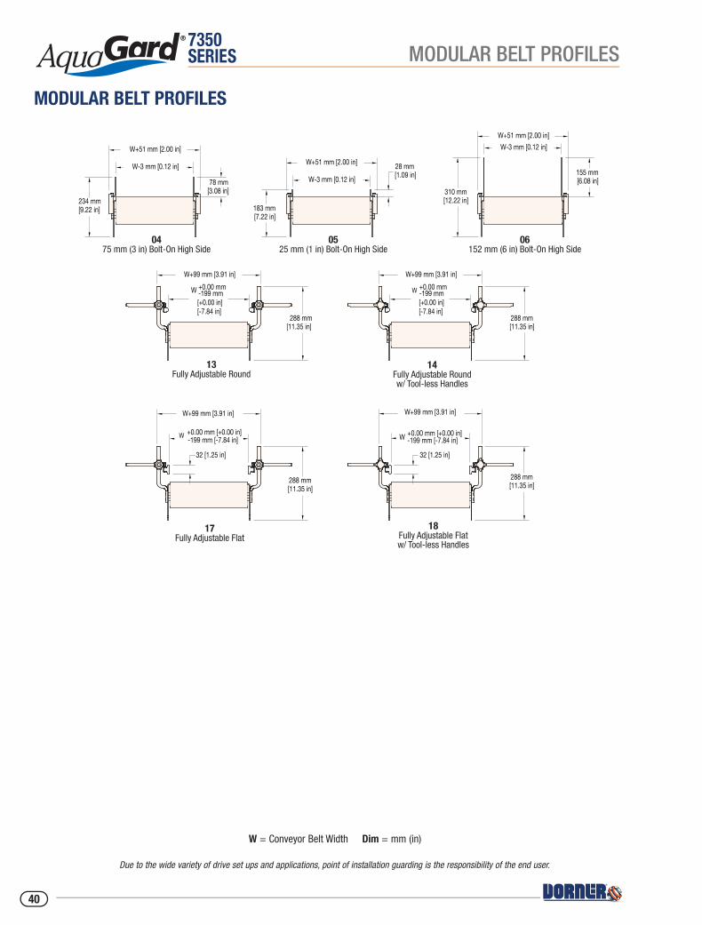
7350SERIES
06152 mm (6 in) Bolt-On High Side
0475 mm (3 in) Bolt-On High Side
0525 mm (1 in) Bolt-On High Side
13Fully Adjustable Round
14Fully Adjustable Roundw/ Tool-less Handles
17Fully Adjustable Flat
18Fully Adjustable Flatw/ Tool-less Handles
234 mm [9.22 in]
W+51 mm [2.00 in]
78 mm [3.08 in]
W+99 mm [3.91 in]
288 mm [11.35 in]
W+99 mm [3.91 in]
288 mm [11.35 in]
W +0.00 mm [+0.00 in]-199 mm [-7.84 in]
32 [1.25 in]
288 mm [11.35 in]
288 mm [11.35 in]
32 [1.25 in]
W +0.00 mm-199 mm[+0.00 in][-7.84 in]
W+99 mm [3.91 in] W+99 mm [3.91 in]
W +0.00 mm [+0.00 in]-199 mm [-7.84 in]
W +0.00 mm-199 mm[+0.00 in][-7.84 in]
W-3 mm [0.12 in]
183 mm [7.22 in]
W+51 mm [2.00 in] 28 mm [1.09 in]W-3 mm [0.12 in]
310 mm [12.22 in]
W+51 mm [2.00 in]
155 mm [6.08 in]
W-3 mm [0.12 in]
MODULAR BELT PROFILES
Due to the wide variety of drive set ups and applications, point of installation guarding is the responsibility of the end user.
W = Conveyor Belt Width Dim = mm (in)
MODULAR BELT PROFILES
40
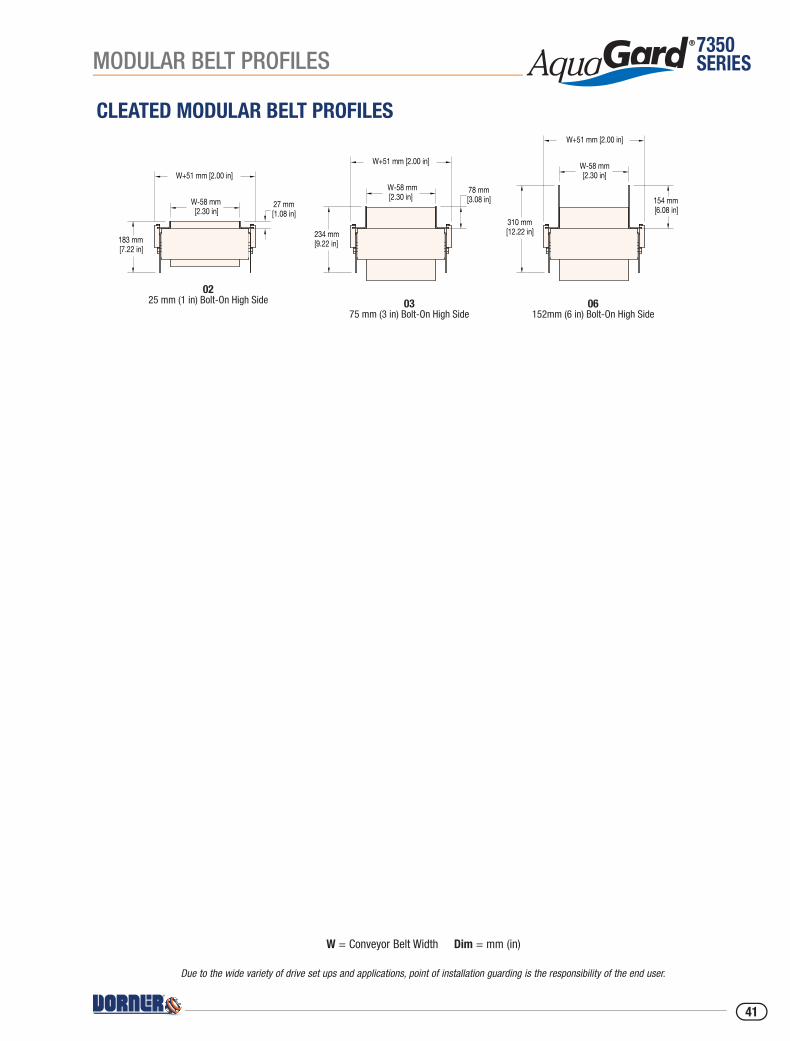
7350SERIES
CLEATED MODULAR BELT PROFILES
0225 mm (1 in) Bolt-On High Side 03
75 mm (3 in) Bolt-On High Side06
152mm (6 in) Bolt-On High Side
183 mm [7.22 in]
W+51 mm [2.00 in]
27 mm [1.08 in]
W-58 mm [2.30 in]
234 mm [9.22 in]
W+51 mm [2.00 in]
78 mm [3.08 in]
W-58 mm [2.30 in]
310 mm [12.22 in]
W+51 mm [2.00 in]
154 mm [6.08 in]
W-58 mm [2.30 in]
MODULAR BELT PROFILES
Due to the wide variety of drive set ups and applications, point of installation guarding is the responsibility of the end user.
W = Conveyor Belt Width Dim = mm (in)
41

7350SERIES
NEW IMAGE
MODULAR BELTING
NEW IMAGE
Friction Insertsare available for incline applications. Inserts may be placed along entire length of the belt or spaced on 51 mm (2 in), 102 mm (4 in), 152 mm (6 in) or 305 mm (12 in) centers. Friction inserts are indented 51 mm (2 in) from each belt edge.
Cleated Beltsprovide a sturdy cleat for elevation at steep inclines. Cleats avail-able in 25 mm (1 in) and 76 mm (3 in) heights.
Curve Beltsprovide a tight radius, space saving corner. Side tabs ensure positive belt tracking with a fl ush top design. Stainless bearings reduce friction providing capability of up to (4) corners.
Flush Grid Beltsprovide an open surface for better drainage, cleaning or air fl ow/cooling.
Flat Top Beltsprovide a closed surface for complete product support, easy wiping.
MODULAR BELT TYPES
42
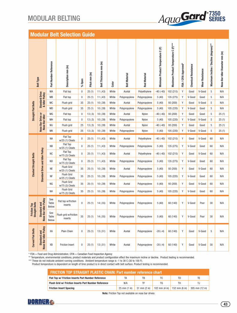
7350SERIES
FRICTION TOP STRAIGHT PLASTIC CHAIN: Part number reference chartFlat Top w/ Friction Inserts Part Number Reference TA TB TC TD TE
Flush Grid w/ Friction Inserts Part Number Reference N/A TF TG TH TJ
Friction Insert Spacing 25 mm (1 in) 51 mm (2 in) 102 mm (4 in) 152 mm (6 in) 305 mm (12 in)
Note: Friction Top not available on nose bar drives
Modular Belt Selection GuideBe
lt Ty
pe
Part
Num
ber R
efer
ence
Desc
riptio
n m
m (i
n)
% O
pen
Pitc
h m
m (i
n)
Belt
Thic
knes
s m
m (i
n)
Colo
r
Belt
Mat
eria
l
Rod
Mat
eria
l
Min
imum
Pro
duct
Tem
pera
ture
C (F
)
Max
imum
Pro
duct
Tem
pera
ture
C (F
)***
FDA
/ CFI
A Ap
prov
ed*
Chem
ical
Res
ista
nce
Wea
r Res
ista
nce
Max
imum
Incl
ine
/ Dec
line
(deg
rees
)**
Nose
Bar
Idle
r Dia
met
er m
m (i
n)
Stra
ight
Fla
t Bel
ts
Stan
dard
Driv
e&
Idle
r Pul
ley MA Flat top 0 25 (1) 11 (.43) White Acetal Polyethylene -40 (-40) 102 (215) Y Good V-Good 5 N/A
MB Flat top 0 25 (1) 11 (.43) White Polypropylene Polypropylene 5 (40) 135 (275) Y V-Good Good 5 N/A
MC Flush grid 35 25 (1) 10 (.39) White Acetal Polypropylene 5 (40) 93 (200) Y Good V-Good 5 N/A
MD Flush grid 35 25 (1) 10 (.39) White Polypropylene Polypropylene 5 (40) 105 (220) Y V-Good Good 5 N/A
Nose
Bar
Driv
e or
No
se B
ar Id
ler MG Flat top 0 13 (.5) 10 (.39) White Acetal Nylon -40 (-40) 93 (200) Y Good Good 5 25 (1)
MH Flat top 0 13 (.5) 10 (.39) White Polypropylene Nylon 5 (40) 105 (220) Y V-Good V-Good 5 25 (1)
MJ Flush grid 25 13 (.5) 10 (.39) White Acetal Nylon -40 (-40) 93 (200) Y Good Good 5 25 (1)
MK Flush grid 25 13 (.5) 10 (.39) White Polypropylene Nylon 5 (40) 105 (220) Y V-Good V-Good 5 25 (1)
Clea
ted
Stra
ight
Bel
ts
Stan
dard
Driv
e an
d Id
ler P
ulle
y
NAFlat Top
w/25 (1) Cleats0 25 (1) 11 (.43) White Acetal Polyethylene -40 (-40) 102 (215) Y Good V-Good 60 N/A
NBFlat Top
w/25 (1) Cleats0 25 (1) 11 (.43) White Polypropylene Polypropylene 5 (40) 135 (275) Y V-Good Good 60 N/A
NCFlat Top
w/75 (3) Cleats0 25 (1) 11 (.43) White Acetal Polyethylene -40 (-40) 102 (215) Y Good V-Good 60 N/A
NDFlat Top
w/75 (3) Cleats0 25 (1) 11 (.43) White Polypropylene Polypropylene 5 (40) 135 (275) Y V-Good Good 60 N/A
NEFlush Grid
w/25 (1) Cleats35 25 (1) 10 (.39) White Acetal Polypropylene 5 (40) 93 (200) Y Good V-Good 60 N/A
NFFlush Grid
w/25 (1) Cleats35 25 (1) 10 (.39) White Polypropylene Polypropylene 5 (40) 105 (220) Y V-Good Good 60 N/A
NGFlush Grid
w/75 (3) Cleats35 25 (1) 10 (.39) White Acetal Polypropylene 5 (40) 93 (200) Y Good V-Good 60 N/A
NHFlush Grid
w/75 (3) Cleats35 25 (1) 10 (.39) White Polypropylene Polypropylene 5 (40) 105 (220) Y V-Good Good 60 N/A
Fric
tion
Top
Stra
ight
Bel
ts
Stan
dard
and
No
se B
ar Id
ler P
ulle
y See Table Below
Flat top w/friction inserts
0 25 (1) 14 (.55) White Polypropylene Polypropylene 5 (40) 60 (140) Y V-Good Poor 30 N/A
See Table Below
Flush grid w/friction inserts
35 25 (1) 14 (.55) White Polypropylene Polypropylene 5 (40) 60 (140) Y V-Good Poor 30 N/A
Curv
ed F
lat B
elts
Stan
dard
and
No
se B
ar Id
ler P
ulle
y
XA Plain Chain 0 25 (1) 13 (.51) White Acetal Polypropylene -20 (-4) 60 (140) Y Good V-Good 5 N/A
XB Friction Insert 0 25 (1) 13 (.51) White Acetal Polypropylene -20 (-4) 60 (140) Y Good V-Good 30 N/A
* FDA = Food and Drug Administration, CFIA = Canadian Food Inspection Agency** Temperature, environmental conditions, product materials and product configuration effect the maximum incline or decline. Product testing is recommended.*** These do not indicate ambient running conditions. Ambient temperature range is -1 to 38 C (30 to 100 F).
Product temperature is dependent on length of time product is in direct contact with belt surface. Product testing is recommended.
MODULAR BELTING
43
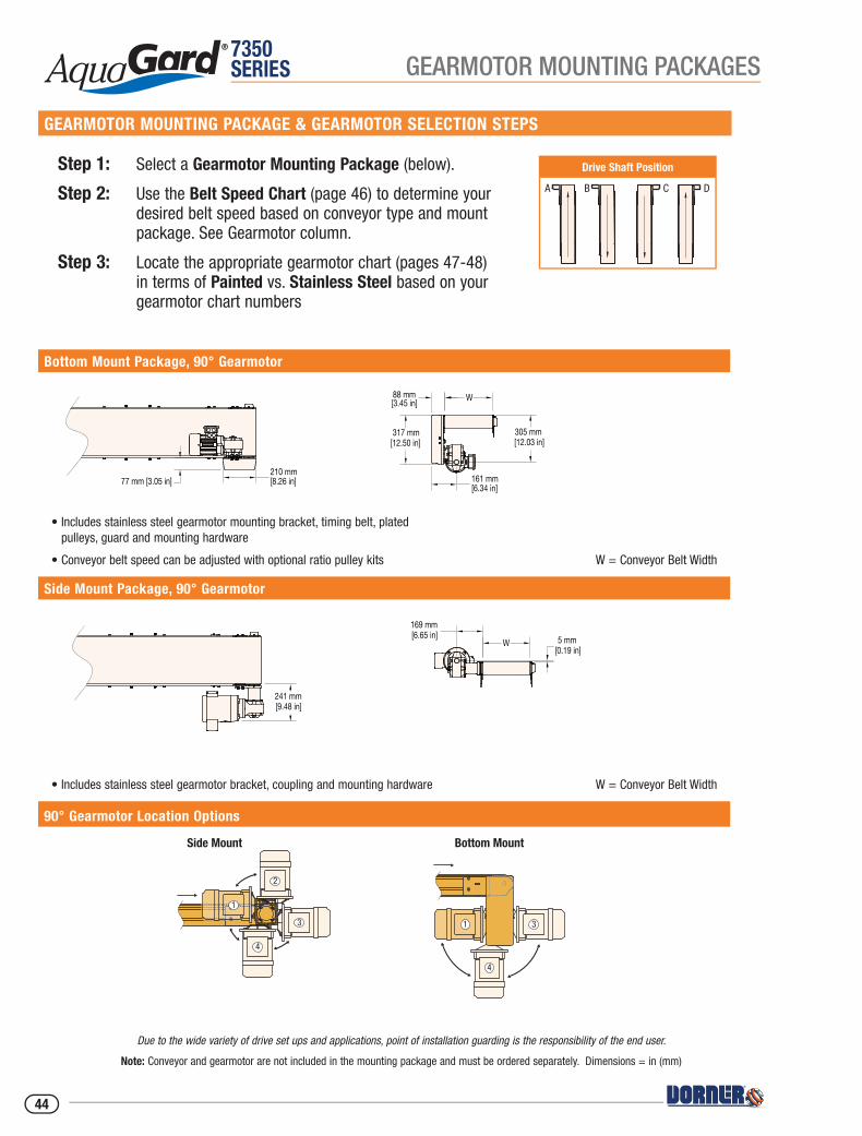
7350SERIES
Drive Shaft Position
GEARMOTOR MOUNTING PACKAGES
GEARMOTOR MOUNTING PACKAGE & GEARMOTOR SELECTION STEPS
Step 1: Select a Gearmotor Mounting Package (below).
Step 2: Use the Belt Speed Chart (page 46) to determine your desired belt speed based on conveyor type and mount package. See Gearmotor column.
Step 3: Locate the appropriate gearmotor chart (pages 47-48) in terms of Painted vs. Stainless Steel based on your gearmotor chart numbers
Bottom Mount Package, 90° Gearmotor
• Includes stainless steel gearmotor mounting bracket, timing belt, plated pulleys, guard and mounting hardware
• Conveyor belt speed can be adjusted with optional ratio pulley kits W = Conveyor Belt Width
Side Mount Package, 90° Gearmotor
• Includes stainless steel gearmotor bracket, coupling and mounting hardware W = Conveyor Belt Width
90° Gearmotor Location Options
Side Mount Package, 90Ā Gearmotor
Bottom Mount Package, 90Ā Gearmotor
77 mm [3.05 in]
317 mm [12.50 in]
169 mm [6.65 in]
W 5 mm [0.19 in]
161 mm [6.34 in]
W
305 mm [12.03 in]
88 mm [3.45 in]
210 mm [8.26 in]
241 mm [9.48 in]
Side Mount Package, 90Ā Gearmotor
Bottom Mount Package, 90Ā Gearmotor
77 mm [3.05 in]
317 mm [12.50 in]
169 mm [6.65 in]
W 5 mm [0.19 in]
161 mm [6.34 in]
W
305 mm [12.03 in]
88 mm [3.45 in]
210 mm [8.26 in]
241 mm [9.48 in]
Due to the wide variety of drive set ups and applications, point of installation guarding is the responsibility of the end user.
Note: Conveyor and gearmotor are not included in the mounting package and must be ordered separately. Dimensions = in (mm)
Side Mount
2
3
4
1
Bottom Mount
1 3
4
Top Mount
1
2
3
44
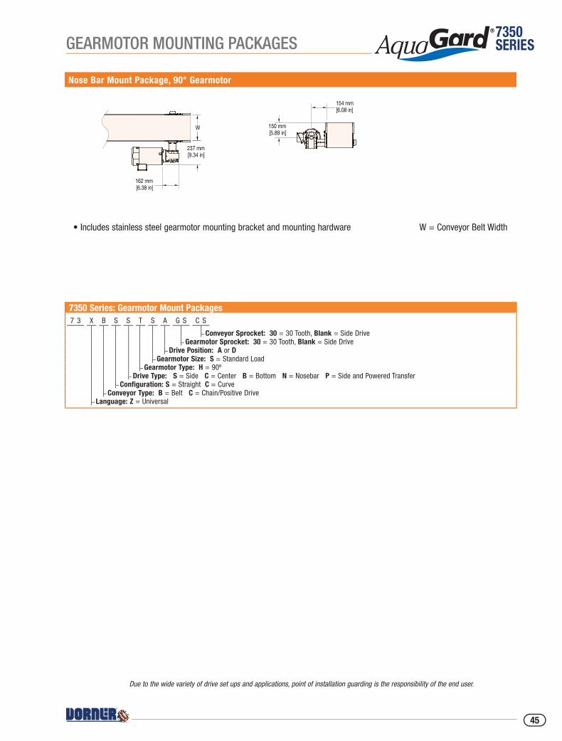
7350SERIESGEARMOTOR MOUNTING PACKAGES
Nose Bar Mount Package, 90° Gearmotor
• Includes stainless steel gearmotor mounting bracket and mounting hardware W = Conveyor Belt Width
7350 Series: Gearmotor Mount Packages7 3 X B S S T S A G S C S
– Conveyor Sprocket: 30 = 30 Tooth, Blank = Side Drive– Gearmotor Sprocket: 30 = 30 Tooth, Blank = Side Drive
– Drive Position: A or D– Gearmotor Size: S = Standard Load
– Gearmotor Type: H = 90º– Drive Type: S = Side C = Center B = Bottom N = Nosebar P = Side and Powered Transfer
– Configuration: S = Straight C = Curve– Conveyor Type: B = Belt C = Chain/Positive Drive
– Language: Z = Universal
Nose Bar Mount Package, 90Ā Gearmotor
150 mm [5.89 in]
162 mm [6.38 in]
154 mm [6.08 in]
W
237 mm [9.34 in]
Due to the wide variety of drive set ups and applications, point of installation guarding is the responsibility of the end user.
45

7350SERIES BELT SPEED CHARTS
Fixed SpeedBelt Speed
RPM From Gearmotor
Mount Package Pulley KitGearmotor
ChartBelted Conveyor Modular Belt Positive Drive BeltBottom Side Drive
PulleyDrivenPulleyft/min m/min ft/min m/min ft/min m/min
26 8 30 9 30 9 29 X X 30 30 1,2
33 10 36 11 36 11 29 X 36 30 1,2
39 12 46 14 46 14 44 X X 30 30 1,2
49 15 52 16 52 16 44 X 36 30 1,2
52 16 59 18 59 18 58 X X 30 30 1,2
62 19 72 22 72 22 58 X 36 30 1,2
79 24 89 27 89 27 87 X X 30 30 1,2
95 29 105 32 105 32 87 X 36 30 1,2
108 33 118 36 118 36 117 X X 30 30 1,2
128 39 141 43 144 44 117 X 36 30 1,2
161 49 177 54 177 54 175 X X 30 30 1,2
194 59 213 65 213 65 175 X 36 30 1,2
Variable SpeedBelt Speed RPM at
60Hz Gearmotor
Mount Package Pulley KitGearmotor
ChartBelted Conveyor Modular Belt Positive Drive BeltBottom Side Drive
PulleyDrivenPulleyft/min m/min ft/min m/min ft/min m/min
3 to 26 1 to 8 3 to 30 1 to 9 3 to 30 1 to 9 29 X X 30 30 3,4
3 to 33 1 to 10 4 to 36 1 to 11 4 to 36 1 to 11 29 X 36 30 3,4
4 to 39 1 to 12 5 to 46 1 to 14 5 to 46 1 to 14 44 X X 30 30 3,4
5 to 49 1 to 15 5 to 52 2 to 16 5 to 52 2 to 16 44 X 36 30 3,4
5 to 52 2 to 16 6 to 59 2 to 18 6 to 59 2 to 18 58 X X 30 30 3,4
6 to 62 2 to 19 7 to 72 2 to 22 7 to 72 2 to 22 58 X 36 30 3,4
8 to 79 2 to 24 9 to 89 3 to 27 9 to 89 3 to 27 87 X X 30 30 3,4
10 to 95 3 to 29 10 to 105 3 to 32 10 to 105 3 to 32 87 X 36 30 3,4
11 to 108 3 to 33 12 to 118 4 to 36 12 to 118 4 to 36 117 X X 30 30 3,4
13 to 128 4 to 39 14 to 141 4 to 43 14 to 144 4 to 44 117 X 36 30 3,4
16 to 161 5 to 49 18 to 177 5 to 54 18 to 177 5 to 54 175 X X 30 30 3,4
19 to 194 6 to 59 21 to 213 7 to 65 21 to 213 7 to 65 175 X 36 30 3,4
46
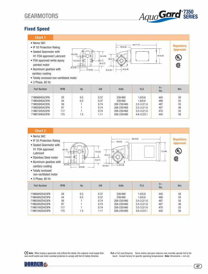
7350SERIESGEARMOTORS
Fixed Speed
Chart 1
• Nema 56C• IP 55 Protection Rating• Sealed Gearmotor with H1 FDA approved Lubricant• FDA approved white epoxy painted motor• Aluminum gearbox with sanitary coating• Totally enclosed non-ventilated motor• 3 Phase, 60 Hz
Part Number RPM Hp kW Volts FLAin.- lbs.
Nm
71M060HS423FN 71M040HS423FN 71M030HS423FN71M020HS423FN71M015HS423FN 71M010HS423FN
29445887117175
0.50.5111
1.5
0.370.370.740.740.741.11
230/460230/460
208-230/460208-230/460208-230/460208-230/460
1.6/0.81.6/0.8
3.5-3.2/1.63.5-3.2/1.63.5-3.2/1.64.6-4.2/2.1
442486487407470442
505555465350
Chart 2
• Nema 56C• IP 55 Protection Rating• Sealed Gearmotor with H1 FDA approved Lubricant• Stainless Steel motor• Aluminum gearbox with sanitary coating• Totally enclosed non-ventilated motor• 3 Phase, 60 Hz
Part Number RPM Hp kW Volts FLAin.- lbs.
Nm
71M060HZS423FN 71M040HZS423FN 71M030HZS423FN71M020HZS423FN71M015HZS423FN 71M010HZS423FN
29445887117175
0.50.5111
1.5
0.370.370.740.740.741.11
230/460230/460
208-230/460208-230/460208-230/460208-230/460
1.6/0.81.6/0.8
3.5-3.2/1.63.5-3.2/1.63.5-3.2/1.64.6-4.2/2.1
442486487407470442
505555465350
Note: When buying a gearmotor only without the starter, the customer must supply their own on/off switch and motor overload protection to comply with the CE Safety Directive.
FLA = Full Load Amperes Some motors and gear reducers may normally operate hot to the touch. Consult factory for specific operating temperatures. Note: Dimensions = mm (in)
Regulatory Approvals
193 (7.60)
110 (4.33)
85 (3.35)212 (8.35)
58 (2.27)
104 (4.09)130 (5.12)
60 (2.36)60 (2.36)
160 (6.30)444 (17.47)
165 (6.50)
85 (3.35)225 (8.88)
55 (2.17)
110 (4.32)
110 (4.33)
198 (7.81)
130 (5.12)
60 (2.36) 60 (2.36)
160 (6.30)
466 (18.33)
177 (6.96)
Regulatory Approvals
47

7350SERIES GEARMOTORS
Variable Speed
Chart 3
• Nema 56C• IP 55 Protection Rating• Sealed Gearmotor with H1 FDA approved Lubricant• FDA approved white epoxy painted motor• Aluminum gearbox with sanitary coating• Totally enclosed non-ventilated motor• 3 Phase, 6 to 60 Hz• Order controller separately
Part Number RPM Hp kW Volts FLAin.- lbs.
Nm
71M060HS423EN 71M040HS423EN 71M030HS423EN71M020HS423EN71M015HS423EN 71M010HS423EN
29445887117175
0.50.5111
1.5
0.370.370.740.740.741.11
230/460230/460
208-230/460208-230/460208-230/460208-230/460
1.6/0.81.6/0.8
3.5-3.2/1.63.5-3.2/1.63.5-3.2/1.64.6-4.2/2.1
442486487407470442
505555465350
Chart 4
• Nema 56C• IP 55 Protection Rating• Sealed Gearmotor with H1 FDA approved Lubricant• Stainless Steel motor• Aluminum gearbox with sanitary coating• Totally enclosed non-ventilated motor• 3 Phase, 6 to 60 Hz• Order controller separately
Part Number RPM Hp kW Volts FLAin.- lbs.
Nm
71M060HZS423EN 71M040HZS423EN 71M030HZS423EN71M020HZS423EN71M015HZS423EN 71M010HZS423EN
29445887117175
0.50.5111
1.5
0.370.370.740.740.741.11
230/460230/460
208-230/460208-230/460208-230/460208-230/460
1.6/0.81.6/0.8
3.5-3.2/1.63.5-3.2/1.63.5-3.2/1.64.6-4.2/2.1
442486487407470442
505555465350
Note: When buying a gearmotor only without the starter, the customer must supply their own on/off switch and motor overload protection to comply with the CE Safety Directive.
FLA = Full Load Amperes Some motors and gear reducers may normally operate hot to the touch. Consult factory for specific operating temperatures. Note: Dimensions = mm (in)
85 (3.35)
193 (7.58)
110 (4.33)
131 (5.16)
58 (2.29)
104 (4.09)
130 (5.12)
60 (2.36) 60 (2.36)
160 (6.30)
165 (6.50)
444 (17.47)
110 (4.33)
198 (7.81)
85 (3.35)225 (8.88)
55 (2.17)
110 (4.32)
60 (2.36)
130 (5.12)
60 (2.36)
160 (6.30)466 (18.33)
177 (6.96)
Regulatory Approvals
Regulatory Approvals
48
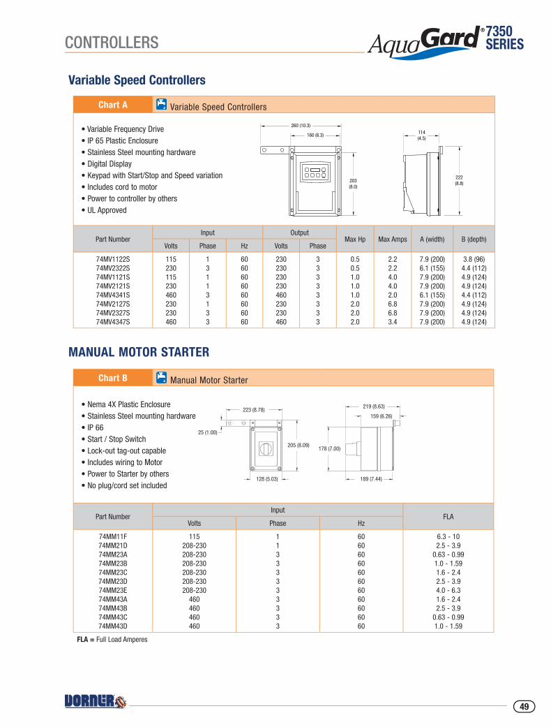
7350SERIESCONTROLLERS
Variable Speed Controllers
Chart A Variable Speed Controllers
• Variable Frequency Drive• IP 65 Plastic Enclosure• Stainless Steel mounting hardware• Digital Display• Keypad with Start/Stop and Speed variation • Includes cord to motor• Power to controller by others• UL Approved
Part NumberInput Output
Max Hp Max Amps A (width) B (depth)Volts Phase Hz Volts Phase
74MV1122S74MV2322S74MV1121S74MV2121S74MV4341S74MV2127S74MV2327S74MV4347S
115230115230460230230460
13113133
6060606060606060
230230230230460230230460
33333333
0.50.51.01.01.02.02.02.0
2.22.24.04.02.06.86.83.4
7.9 (200)6.1 (155)7.9 (200)7.9 (200)6.1 (155)7.9 (200)7.9 (200)7.9 (200)
3.8 (96)4.4 (112)4.9 (124)4.9 (124)4.4 (112)4.9 (124)4.9 (124)4.9 (124)
MANUAL MOTOR STARTER
Chart B Manual Motor Starter
• Nema 4X Plastic Enclosure• Stainless Steel mounting hardware• IP 66• Start / Stop Switch• Lock-out tag-out capable• Includes wiring to Motor• Power to Starter by others• No plug/cord set included
Part NumberInput
FLAVolts Phase Hz
74MM11F 74MM21D74MM23A74MM23B74MM23C74MM23D74MM23E74MM43A74MM43B 74MM43C74MM43D
115208-230208-230208-230208-230208-230208-230
460460460460
11333333333
6060606060606060606060
6.3 - 102.5 - 3.9
0.63 - 0.991.0 - 1.591.6 - 2.42.5 - 3.94.0 - 6.31.6 - 2.42.5 - 3.9
0.63 - 0.991.0 - 1.59
FLA = Full Load Amperes
203(8.0)
260 (10.3)
160 (6.3) 114(4.5)
222(8.8)
223 (8.78)
25 (1.00)
128 (5.03)
205 (8.09)178 (7.00)
189 (7.44)
219 (8.63)
159 (6.26)
49
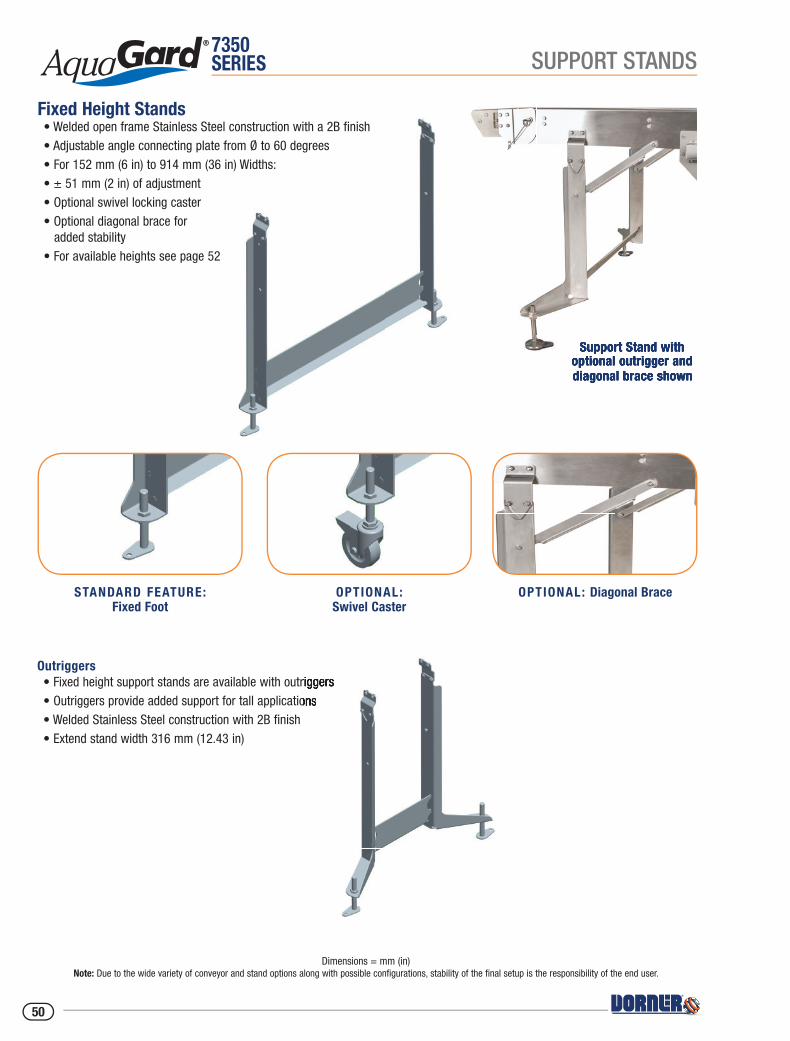
7350SERIES
OPTIONAL: Diagonal BraceOPTIONAL:Swivel Caster
STANDARD FEATURE:Fixed Foot
Support Stand with optional outrigger and diagonal brace shown
SUPPORT STANDS
Outriggers• Fixed height support stands are available with outriggers• Outriggers provide added support for tall applications• Welded Stainless Steel construction with 2B fi nish• Extend stand width 316 mm (12.43 in)
Fixed Height Stands• Welded open frame Stainless Steel construction with a 2B fi nish• Adjustable angle connecting plate from Ø to 60 degrees • For 152 mm (6 in) to 914 mm (36 in) Widths:• ± 51 mm (2 in) of adjustment• Optional swivel locking caster• Optional diagonal brace for added stability• For available heights see page 52
Dimensions = mm (in)Note: Due to the wide variety of conveyor and stand options along with possible configurations, stability of the final setup is the responsibility of the end user.
• Fixed height support stands are available with outriggers• Outriggers provide added support for tall applications
Support Stand with Support Stand with optional outrigger and optional outrigger and diagonal brace showndiagonal brace shown
50
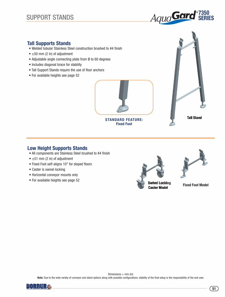
7350SERIES
STANDARD FEATURE:Fixed Foot
SUPPORT STANDS
Tall Stand
Swivel Locking Caster Model
Tall Supports Stands• Welded tubular Stainless Steel construction brushed to #4 finish• ±50 mm (2 in) of adjustment• Adjustable angle connecting plate from Ø to 60 degrees • Includes diagonal brace for stability• Tall Support Stands require the use of floor anchors• For available heights see page 52
Low Height Supports Stands • All components are Stainless Steel brushed to #4 fi nish• ±51 mm (2 in) of adjustment• Fixed Foot self-aligns 10° for sloped floors• Caster is swivel locking• Horizontal conveyor mounts only• For available heights see page 52
Tall Stand
Swivel Locking Caster Model
Fixed Foot Model
Dimensions = mm (in)Note: Due to the wide variety of conveyor and stand options along with possible configurations, stability of the final setup is the responsibility of the end user.
51
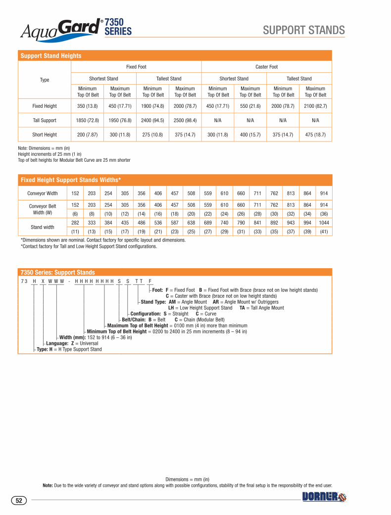
7350SERIES SUPPORT STANDS
Dimensions = mm (in)Note: Due to the wide variety of conveyor and stand options along with possible configurations, stability of the final setup is the responsibility of the end user.
7350 Series: Support Stands7 3 H X W W W - H H H H H H H H S S T T F
– Foot: F = Fixed Foot B = Fixed Foot with Brace (brace not on low height stands) C = Caster with Brace (brace not on low height stands)
– Stand Type: AM = Angle Mount AR = Angle Mount w/ Outriggers LH = Low Height Support Stand TA = Tall Angle Mount
– Configuration: S = Straight C = Curve– Belt/Chain: B = Belt C = Chain (Modular Belt)
– Maximum Top of Belt Height = 0100 mm (4 in) more than minimum– Minimum Top of Belt Height = 0200 to 2400 in 25 mm increments (8 – 94 in)
– Width (mm): 152 to 914 (6 – 36 in)– Language: Z = Universal
– Type: H = H Type Support Stand
Fixed Height Support Stands Widths*
Conveyor Width 152 203 254 305 356 406 457 508 559 610 660 711 762 813 864 914
Conveyor Belt Width (W)
152 203 254 305 356 406 457 508 559 610 660 711 762 813 864 914
(6) (8) (10) (12) (14) (16) (18) (20) (22) (24) (26) (28) (30) (32) (34) (36)
Stand width282 333 384 435 486 536 587 638 689 740 790 841 892 943 994 1044
(11) (13) (15) (17) (19) (21) (23) (25) (27) (29) (31) (33) (35) (37) (39) (41)
*Dimensions shown are nominal. Contact factory for specific layout and dimensions.*Contact factory for Tall and Low Height Support Stand confi gurations.
Support Stand Heights
Type
Fixed Foot Caster Foot
Shortest Stand Tallest Stand Shortest Stand Tallest Stand
Minimum Top Of Belt
MaximumTop Of Belt
Minimum Top Of Belt
MaximumTop Of Belt
Minimum Top Of Belt
MaximumTop Of Belt
Minimum Top Of Belt
MaximumTop Of Belt
Fixed Height 350 (13.8) 450 (17.71) 1900 (74.8) 2000 (78.7) 450 (17.71) 550 (21.6) 2000 (78.7) 2100 (82.7)
Tall Support 1850 (72.8) 1950 (76.8) 2400 (94.5) 2500 (98.4) N/A N/A N/A N/A
Short Height 200 (7.87) 300 (11.8) 275 (10.8) 375 (14.7) 300 (11.8) 400 (15.7) 375 (14.7) 475 (18.7)
Note: Dimensions = mm (in)Height increments of 25 mm (1 in)Top of belt heights for Modular Belt Curve are 25 mm shorter
52

7350SERIESSUPPORTS & STAND ACCESSORIES
Dimensions = mm (in)Note: Due to the wide variety of conveyor and stand options along with possible configurations, stability of the final setup is the responsibility of the end user.
Sanitary Floor Anchor Kits - Type 1
Specifications• 10 mm (.375 in) x 40 mm (1.57 in) drop in• Stainless Steel• Anchor is fl ush with fl oor upon removal of bolt• Two (2) per anchor kit
Sanitary Floor Anchor Kits - Type 2
Specifications• 10 mm (.375 in) x 70 mm (2.75 in)• Stainless Steel• Threaded anchor bolt protrudes above fl oor after installation• Two (2) per anchor kit
Part Number FAS-1
Part Number FAS-2
Horizontal Ceiling Supports
Adjustable Angle Ceiling Supports
Specifications• All components are Stainless Steel brushed to #4 finish
• Includes a pair of mounting brackets and hardware for support on both sides of conveyor
• Compatible with 12 mm (0.5 in) threaded support rod (not provided)
Specifications• All components are Stainless Steel brushed to #4 finish
• Includes a pair of mounting brackets and hardware for support on both sides of conveyor
• Compatible with 12 mm (0.5 in) threaded support rod (not provided)
• Mounting block pivots to support incline mounts from 0° to 60°
Part Number 73HCS
Part Number 73ACS
53

7350SERIES ACCESSORIES
7350 Series: Photo Eye Bracket - Accessory Mounting Bar Style7 3 5 2 P M - F P
- Post Type: NP = Fixed Post w/o post included FP = Fixed Post w/ post included AM = Accessory Mount
– Mount Type: PM = Photoeye Mount RM = Reflective Mount CM = Convergent Mount
Dimensions = mm (in)Note: Due to the wide variety of conveyor and stand options along with possible configurations, stability of the final setup is the responsibility of the end user.
Accessory Mounting BarSpecifications• Used for mounting adjustable devices such as photoeyes and sensors• Can be mounted directly to frame or in combination with guide brackets• Includes 1248 mm (48 in) long bar with (3) mounting brackets (Bar can be cut to length as needed)• Compatible with Value Guide blocks (VG-021-02)• All brackets and fasteners are Stainless Steel
Specifications• Mounts standard 18 mm (0.71 in) barrel or nose mount photo eyes or sensors• Attach bracket or accessories without frame modifications• Adjustable along the length of the conveyor• Adjustable height and angle positioning• All adjustment screws located outside the food zone• (3) Photo Eye Types • Thru beam includes (2) mounts • Reflector includes (1) photo eye mount and (1) reflector mound
(reflector included)• Accessory Mounting Bar Style: (3) Mount versions: • To fixed post (does not include mounting post) • To fixed post (includes mounting post) • To accessory mounting bar (includes Value Guide Block
and adjustable post)
Photo Eye and Reflector Mounting Brackets
Specifications• Used for mounting adjustable devices such as photoeyes and sensors• Can be mounted directly to frame or in combination with guide brackets• Includes 1248 mm (48 in) long bar with (3) mounting brackets (Bar can be cut to length as needed)• Compatible with Value Guide blocks (VG-021-02)• All brackets and fasteners are Stainless Steel
Part Number 517509 Bar Assembly 1248 mm (48 in) long
54
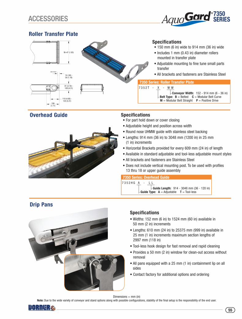
7350SERIESACCESSORIES
Dimensions = mm (in)Note: Due to the wide variety of conveyor and stand options along with possible configurations, stability of the final setup is the responsibility of the end user.
Drip PansSpecifications• Widths: 152 mm (6 in) to 1524 mm (60 in) available in
50 mm (2 in) increments
• Lengths: 610 mm (24 in) to 25375 mm (999 in) available in 25 mm (1 in) increments maximum section lengths of 2997 mm (118 in)
• Tool-less hook design for fast removal and rapid cleaning
• Provides a 50 mm (2 in) window for clean-out access without removal
• All pans equipped with a 25 mm (1 in) containment lip on all sides
• Contact factory for additional options and ordering
W+47 (1.85)
END OF BELT
14 (.56) -30 (1.18)
119 (4.69) -135 (5.31)
196(7.71)
81 (3.18) -109 (4.31)
7350 Series: Overhead Guide7 3 5 2 H G A - L L
– Guide Length: 914 - 3048 mm (36 - 120 in)– Guide Type: A = Adjustable T = Tool-less
Roller Transfer PlateSpecifications• 150 mm (6 in) wide to 914 mm (36 in) wide• Includes 1 mm (0.43 in) diameter rollers mounted in transfer plate• Adjustable mounting to fine tune small parts transfer• All brackets and fasteners are Stainless Steel
Specifications• For part hold down or cover closing• Adjustable height and position across width• Round nose UHMW guide with stainless steel backing• Lengths: 914 mm (36 in) to 3048 mm (1200 in) in 25 mm (1 in) increments• Horizontal Brackets provided for every 609 mm (24 in) of length• Available in standard adjustable and tool-less adjustable mount styles• All brackets and fasteners are Stainless Steel• Does not include vertical mounting post. To be used with profiles
13 thru 18 or upper guide assembly
Overhead Guide
7350 Series: Roller Transfer Plate7 3 5 2 T - X - W W
– Conveyor Width: 152 - 914 mm (6 - 36 in)– Belt Type: B = Belted C = Modular Belt Curve M = Modular Belt Straight P = Positive Drive
55
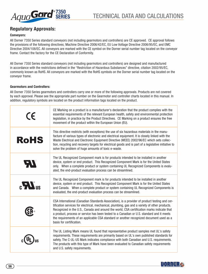
7350SERIES TECHNICAL DATA AND CALCULATIONS
Regulatory Approvals:Conveyors:
All Dorner 7350 Series standard conveyors (not including gearmotors and controllers) are CE approved. CE approval follows the provisions of the following directives; Machine Directive 2006/42/EC, EU Low Voltage Directive 2006/95/EC, and EMC Directive 2004/108/EC. All conveyors are marked with the CE symbol on the Dorner serial number tag located on the conveyor frame. Contact the factory for the CE Declaration of Conformity.
All Dorner 7350 Series standard conveyors (not including gearmotors and controllers) are designed and manufactured in accordance with the restrictions defi ned in the “Restriction of Hazardous Substances” directive, citation 2002/95/EC, commonly known as RoHS. All conveyors are marked with the RoHS symbols on the Dorner serial number tag located on the conveyor frame.
Gearmotors and Controllers:
All Dorner 7350 Series gearmotors and controllers carry one or more of the following approvals. Products are not covered by each approval. Please see the appropriate part number on the Gearmotor and controller charts located in this manual. In addition, regulatory symbols are located on the product information tags located on the product.
CE Marking on a product is a manufacturer's declaration that the product complies with the essential requirements of the relevant European health, safety and environmental protection legislation, in practice by the Product Directives. CE Marking on a product ensures the free movement of the product within the European Union (EU).
This directive restricts (with exceptions) the use of six hazardous materials in the manu-facture of various types of electronic and electrical equipment. It is closely linked with the Waste Electrical and Electronic Equipment Directive (WEEE) 2002/96/EC which sets collec-tion, recycling and recovery targets for electrical goods and is part of a legislative initiative to solve the problem of huge amounts of toxic e-waste.
The UL Recognized Component mark is for products intended to be installed in another device, system or end product. This Recognized Component Mark is for the United States only. When a complete product or system containing UL Recognized Components is evalu-ated, the end-product evaluation process can be streamlined.
The UL Recognized Component mark is for products intended to be installed in another device, system or end product. This Recognized Component Mark is for the United States and Canada. When a complete product or system containing UL Recognized Components is evaluated, the end-product evaluation process can be streamlined.
CSA International (Canadian Standards Association), is a provider of product testing and cer-tification services for electrical, mechanical, plumbing, gas and a variety of other products. Recognized in the U.S., Canada and around the world, CSA certification marks indicate that a product, process or service has been tested to a Canadian or U.S. standard and it meets the requirements of an applicable CSA standard or another recognized document used as a basis for certification.
The UL Listing Mark means UL found that representative product samples met UL's safety requirements. These requirements are primarily based on UL's own published standards for safety. The C-UL-US Mark indicates compliance with both Canadian and U.S. requirements. The products with this type of Mark have been evaluated to Canadian safety requirements and U.S. safety requirements.
56

7350SERIESTECHNICAL DATA AND CALCULATIONS
Baking Industry Standards and Certifications:
AquaGard 7350 Series Conveyors are often used in food production or food packaging areas where proper design of equipment is essential to maintain proper food safety. AquaGard 7350 Series conveyors are designed for light wash down environments typically seen in packaged food, dry food production or confectionary production. In these applications the correct installation and application of the conveyor is critical to the proper running of the conveyor and maintaining proper food safety. The end user must ensure that the conveyor belts are properly tracked and the conveyor is properly installed as defi ned by Dorner.
All AquaGard 7350 Series products are designed and constructed to be used in dry food or packaged food production environments. The following AquaGard products have gone through testing and certifi cation and are certifi ed to BISSC standard, design requirements for Conveyors section of ANSI/ASB/Z50.2-2015.
7350 Series Belted Conveyor 7350 Series Modular Belt Conveyor 7350 Series Positive Drive Belted Conveyor
Contact the factory for copy of the certifi cation.
57
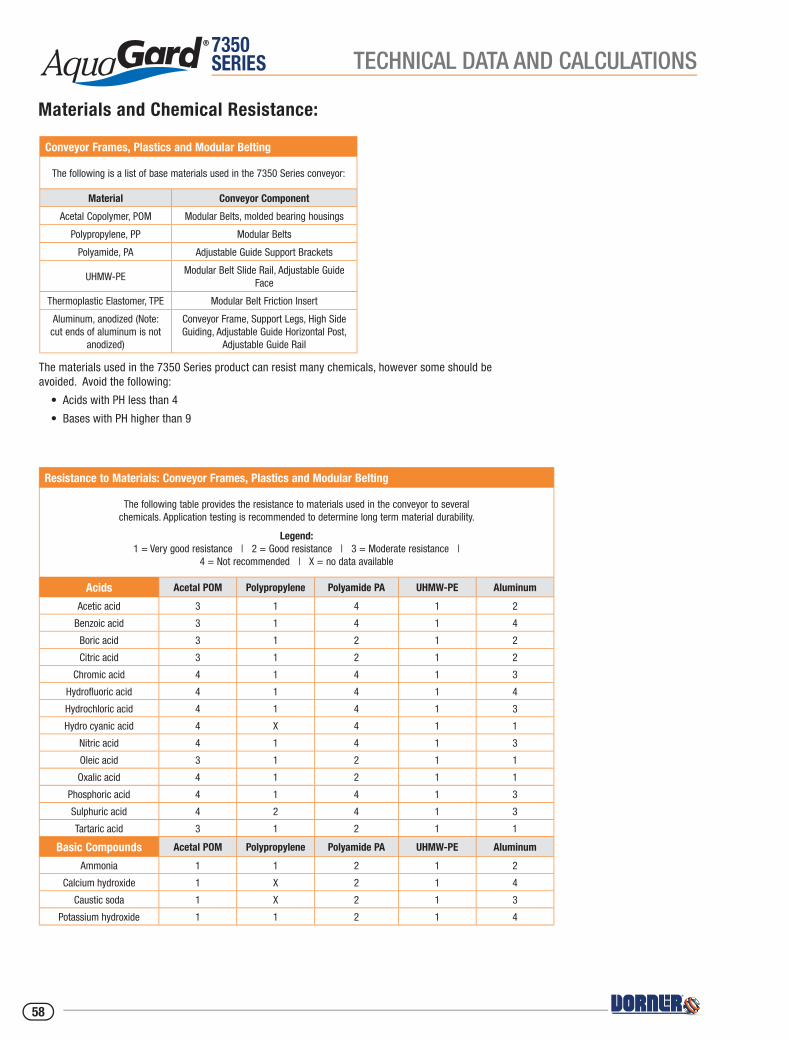
7350SERIES TECHNICAL DATA AND CALCULATIONS
The materials used in the 7350 Series product can resist many chemicals, however some should be avoided. Avoid the following:
• Acids with PH less than 4
• Bases with PH higher than 9
Conveyor Frames, Plastics and Modular Belting
The following is a list of base materials used in the 7350 Series conveyor:
Material Conveyor Component
Acetal Copolymer, POM Modular Belts, molded bearing housings
Polypropylene, PP Modular Belts
Polyamide, PA Adjustable Guide Support Brackets
UHMW-PEModular Belt Slide Rail, Adjustable Guide
Face
Thermoplastic Elastomer, TPE Modular Belt Friction Insert
Aluminum, anodized (Note: cut ends of aluminum is not
anodized)
Conveyor Frame, Support Legs, High Side Guiding, Adjustable Guide Horizontal Post,
Adjustable Guide Rail
Materials and Chemical Resistance:
Resistance to Materials: Conveyor Frames, Plastics and Modular Belting
The following table provides the resistance to materials used in the conveyor to several chemicals. Application testing is recommended to determine long term material durability.
Legend:1 = Very good resistance | 2 = Good resistance | 3 = Moderate resistance |
4 = Not recommended | X = no data available
Acids Acetal POM Polypropylene Polyamide PA UHMW-PE Aluminum
Acetic acid 3 1 4 1 2
Benzoic acid 3 1 4 1 4
Boric acid 3 1 2 1 2
Citric acid 3 1 2 1 2
Chromic acid 4 1 4 1 3
Hydrofl uoric acid 4 1 4 1 4
Hydrochloric acid 4 1 4 1 3
Hydro cyanic acid 4 X 4 1 1
Nitric acid 4 1 4 1 3
Oleic acid 3 1 2 1 1
Oxalic acid 4 1 2 1 1
Phosphoric acid 4 1 4 1 3
Sulphuric acid 4 2 4 1 3
Tartaric acid 3 1 2 1 1
Basic Compounds Acetal POM Polypropylene Polyamide PA UHMW-PE Aluminum
Ammonia 1 1 2 1 2
Calcium hydroxide 1 X 2 1 4
Caustic soda 1 X 2 1 3
Potassium hydroxide 1 1 2 1 4
58

7350SERIESTECHNICAL DATA AND CALCULATIONS
Resistance to Materials: Conveyor Frames, Plastics and Modular Belting (continued)
Legend:1 = Very good resistance | 2 = Good resistance | 3 = Moderate resistance |
4 = Not recommended | X = no data available
Salts Acetal POM Polypropylene Polyamide PA UHMW-PE Aluminum
Potassium bicarbonate 2 X 2 1 1
Potassium permanganate 2 2 4 1 1
Sodium cyanic 2 X 2 1 4
Sodium hydrochloride 3 X 4 1 4
Acid salt 2 X 3 1 X
Basic salt 1 X 2 1 X
Neutral salt 1 X 2 1 X
Organic Compounds Acetal POM Polypropylene Polyamide PA UHMW-PE Aluminum
Acetone 1 1 1 1 1
Aniline 2 1 3 1 1
Benzene 1 3 2 4 1
Benzine 2 X 2 3 1
Butyl alcohol 2 X 2 1 1
Carbon disulphide 1 3 2 3 1
Carbon tetrachloride 1 3 1 3 2
Chloroform 1 4 3 4 X
Ethyl acetate 1 1 2 1 1
Ethyl alcohol 1 X 2 1 1
Heptane 2 1 1 2 X
Methyl alcohol 1 X 2 1 2
Methyl ethyl ketone 1 2 1 2 2
Nitrobenzene 2 2 2 1 1
Phenol 3 1 4 1 1
Gases Acetal POM Polypropylene Polyamide PA UHMW-PE Aluminum
Carbon dioxide 3 1 1 1 1
Carbon monoxide 2 X 1 1 1
Chlorine 2 4 4 3 1
Hydrogen Sulfi de 3 1 1 1 1
Sulphur dioxide 2 1 3 1 1
Other Acetal POM Polypropylene Polyamide PA UHMW-PE Aluminum
Carbon tetrachloride 1 3 1 3 2
Beer 1 1 2 1 1
Fruit juice 1 2 2 1 2
Gasoline 1 1 2 1 1
Milk 1 1 1 1 1
Oil 1 3 1 1 1
Vinegar 1 1 2 1 1
59
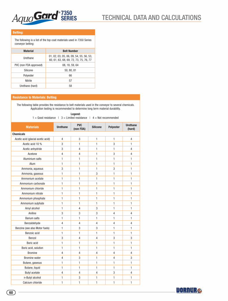
7350SERIES TECHNICAL DATA AND CALCULATIONS
Belting:
The following is a list of the top coat materials used in 7350 Series conveyor belting:
Material Belt Number
Urethane01, 02, 03, 05, 06, 09, 54, 55, 56, 53, 60, 61, 63, 68, 69, 72, 73, 75, 76, 77
PVC (non FDA approved) 08, 18, 59, 64
Silicone 50, 80, 81
Polyester 66
Nitrile 57
Urethane (hard) 58
Resistance to Materials: Belting
The following table provides the resistance to belt materials used in the conveyor to several chemicals. Application testing is recommended to determine long term material durability.
Legend:1 = Good resistance | 3 = Limited resistance | 4 = Not recommended
Materials UrethanePVC
(non FDA)Silicone Polyester
Urethane (hard)
Chemicals
Acetic acid (glacial acetic acid) 4 3 1 1 4
Acetic acid 10 % 3 1 1 3 1
Acetic anhydride 3 4 1 1 4
Acetone 4 4 1 3 4
Aluminium salts 1 1 1 1 1
Alum 1 1 1 1 1
Ammonia, aqueous 3 1 1 3 1
Ammonia, gaseous 1 1 3 1 1
Ammonium acetate 1 1 1 1 1
Ammonium carbonate 1 1 1 1 1
Ammonium chloride 1 1 1 1 1
Ammonium nitrate 1 1 1 1 1
Ammonium phosphate 1 1 1 1 1
Ammonium sulphate 1 1 1 1 1
Amyl alcohol 1 4 3 1 1
Aniline 3 3 3 4 4
Barium salts 1 1 1 1 1
Benzaldehyde 4 4 4 4 4
Benzine (see also Motor fuels) 1 3 3 1 1
Benzoic acid 1 1 1 1 1
Benzol 3 4 4 3 3
Boric acid 1 1 1 1 1
Boric acid, solution 1 1 1 1 1
Bromine 4 4 4 4 4
Bromine water 4 3 1 4 3
Butane, gaseous 1 1 1 1 1
Butane, liquid 1 1 1 1 1
Butyl acetate 4 4 4 3 4
n-Butyl alcohol 1 3 1 1 1
Calcium chloride 1 1 1 1 1
60
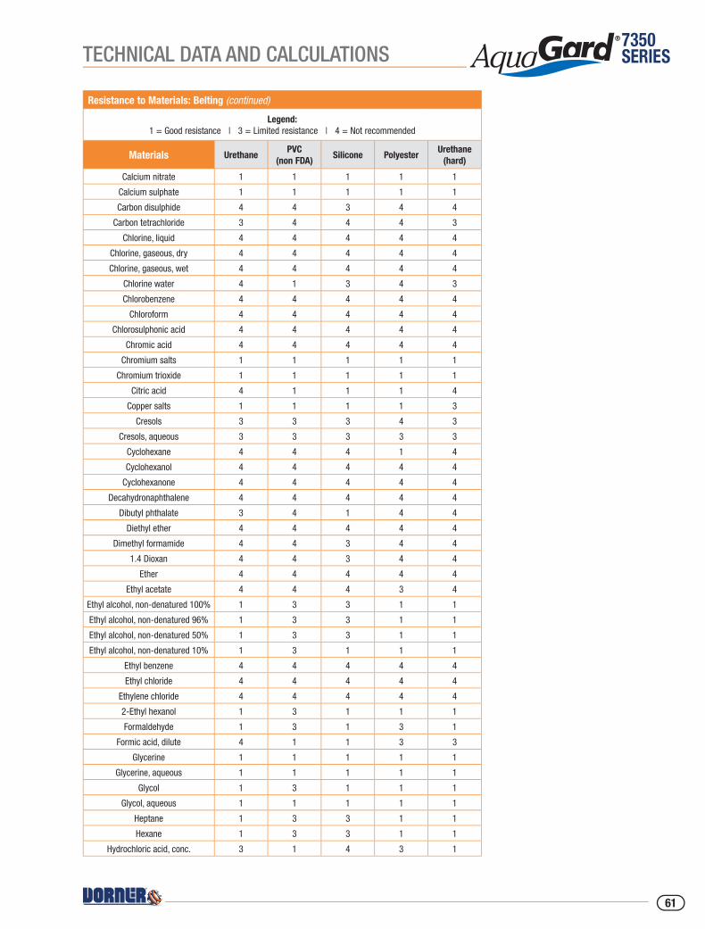
7350SERIESTECHNICAL DATA AND CALCULATIONS
Resistance to Materials: Belting (continued)
Legend:1 = Good resistance | 3 = Limited resistance | 4 = Not recommended
Materials UrethanePVC
(non FDA)Silicone Polyester
Urethane (hard)
Calcium nitrate 1 1 1 1 1
Calcium sulphate 1 1 1 1 1
Carbon disulphide 4 4 3 4 4
Carbon tetrachloride 3 4 4 4 3
Chlorine, liquid 4 4 4 4 4
Chlorine, gaseous, dry 4 4 4 4 4
Chlorine, gaseous, wet 4 4 4 4 4
Chlorine water 4 1 3 4 3
Chlorobenzene 4 4 4 4 4
Chloroform 4 4 4 4 4
Chlorosulphonic acid 4 4 4 4 4
Chromic acid 4 4 4 4 4
Chromium salts 1 1 1 1 1
Chromium trioxide 1 1 1 1 1
Citric acid 4 1 1 1 4
Copper salts 1 1 1 1 3
Cresols 3 3 3 4 3
Cresols, aqueous 3 3 3 3 3
Cyclohexane 4 4 4 1 4
Cyclohexanol 4 4 4 4 4
Cyclohexanone 4 4 4 4 4
Decahydronaphthalene 4 4 4 4 4
Dibutyl phthalate 3 4 1 4 4
Diethyl ether 4 4 4 4 4
Dimethyl formamide 4 4 3 4 4
1.4 Dioxan 4 4 3 4 4
Ether 4 4 4 4 4
Ethyl acetate 4 4 4 3 4
Ethyl alcohol, non-denatured 100% 1 3 3 1 1
Ethyl alcohol, non-denatured 96% 1 3 3 1 1
Ethyl alcohol, non-denatured 50% 1 3 3 1 1
Ethyl alcohol, non-denatured 10% 1 3 1 1 1
Ethyl benzene 4 4 4 4 4
Ethyl chloride 4 4 4 4 4
Ethylene chloride 4 4 4 4 4
2-Ethyl hexanol 1 3 1 1 1
Formaldehyde 1 3 1 3 1
Formic acid, dilute 4 1 1 3 3
Glycerine 1 1 1 1 1
Glycerine, aqueous 1 1 1 1 1
Glycol 1 3 1 1 1
Glycol, aqueous 1 1 1 1 1
Heptane 1 3 3 1 1
Hexane 1 3 3 1 1
Hydrochloric acid, conc. 3 1 4 3 1
61

7350SERIES TECHNICAL DATA AND CALCULATIONS
Resistance to Materials: Belting (continued)
Legend:1 = Good resistance | 3 = Limited resistance | 4 = Not recommended
Materials UrethanePVC
(non FDA)Silicone Polyester
Urethane (hard)
Hydrochloric acid 10 % 3 1 1 1 1
Hydrofl uoric acid 40 % 4 4 4 4 4
Hydrogen chloride, gaseous, dilute 3 1 3 3 1
Hydrogen chloride, gaseous, conc. 3 3 3 4 3
Hydrogen peroxide 10% 3 1 1 3 1
Hydrogen sulphide 3 3 3 3 3
Iron salts (sulphate) 1 1 1 1 1
Isooctane 1 3 3 1 1
Isopropyl alcohol 1 3 1 1 1
Lactic acid 1 3 1 1 1
Magnesium salts 1 1 1 1 1
Mercury 1 1 1 1 1
Mercury salts 1 1 1 1 1
Methyl alcohol, aqueous 50 % 3 3 1 1 1
Methyl alcohol (methanol) 1 3 1 1 1
Methyl ethyl ketone 4 4 1 3 4
Methylene chloride 4 4 4 4 4
Naphthalene 3 4 4 3 4
Nickel salts 1 1 1 1 1
Nitric acid 4 3 4 4 4
Nitrobenzene 4 4 1 3 4
Octane (see also isooctane) 1 3 4 1 1
Oleic acid 1 3 4 1 1
Oxalic acid 1 1 1 1 1
Ozone 1 3 3 1 3
Perchloroethylene 4 4 4 4 4
Phenol 3 3 1 4 3
Phenol, aqueous 4 3 1 4 3
Phosphoric acid 85 % 4 1 1 3 1
Phosphoric acid 50 % 1 1 1 1 1
Phosphoric acid 10 % 1 1 1 1 1
Phosphorus pentoxide 1 1 1 1 1
Potash lye 50 % 4 1 4 3 4
Potash lye 25 % 4 1 4 1 4
Potash lye 10 % 4 1 3 1 4
Potassium carbonate (potash) 1 1 1 1 1
Potassium chlorate 1 1 1 1 1
Potassium chloride 1 1 1 1 1
Potassium dichromate 1 1 1 1 1
Potassium iodide 1 1 1 1 1
Potassium nitrate 1 1 1 1 1
Potassium permanganate 1 1 1 1 1
Potassium persulphate 1 1 1 1 1
Potassium sulphate 1 1 1 1 1
Propane, gaseous 1 1 1 1 1
Propane, liquid 1 1 1 1 1
62

7350SERIESTECHNICAL DATA AND CALCULATIONS
Resistance to Materials: Belting (continued)
Legend:1 = Good resistance | 3 = Limited resistance | 4 = Not recommended
Materials UrethanePVC
(non FDA)Silicone Polyester
Urethane (hard)
Pyridine 4 4 3 4 4
Silver salts 1 1 1 1 1
Soda lye 50% (see potash lye) 4 1 4 4 4
Soda lye 25% 4 1 4 3 4
Soda lye 10% 4 1 3 1 4
Sodium bisulphite 1 1 1 1 1
Sodium carbonate (natron) 1 1 1 1 1
Sodium carbonate (soda) 1 1 1 1 1
Sodium chlorate 1 1 1 1 1
Sodium chloride (common salt) 1 1 1 1 1
Sodium hydroxide (caustic soda) 4 1 4 1 4
Sodium hypochlorite 1 1 1 3 1
Sodium nitrate 1 1 1 1 1
Sodium nitrite 1 1 1 1 1
Sodium perborate 1 1 1 1 1
Sodium phosphate 1 1 1 1 1
Sodium sulphate (Glauber salt) 1 1 1 1 1
Sodium sulphide 1 1 1 1 1
Sodium sulphite 1 1 1 1 1
Sodium thiosulphate (fi xing salt) 1 1 1 1 1
Stearic acid 1 1 1 1 1
Succinic acid 1 1 1 1 1
Sulphur 1 1 1 1 1
Sulphur dioxide 3 3 3 3 4
Sulphuric acid 96% 4 4 4 4 4
Sulphuric acid 50% 4 3 4 3 4
Sulphuric acid 25% 4 3 3 1 3
Sulphuric acid 10% 4 3 1 1 3
Tartaric acids 1 1 1 1 1
Tetrachloroethane 4 4 4 4 4
Tetrachloroethylene (perchloroethylene)
4 4 4 4 4
Tetrahydrofuran 4 4 4 4 4
Tetrahydronaphthalene 4 4 4 4 4
Thiophene 4 4 4 4 4
Tin II chlorides 1 1 1 1 1
Toluene 4 4 4 4 4
Trichloroethylene 4 4 4 4 4
Urea, aqueous 1 1 1 1 1
Water 1 1 1 1 1
Xylene 4 4 4 3 4
Zinc salts 1 1 1 1 1
63

7350SERIES TECHNICAL DATA AND CALCULATIONS
Resistance to Materials: Belting (continued)
Legend:1 = Good resistance | 3 = Limited resistance | 4 = Not recommended
Materials UrethanePVC
(non FDA)Silicone Polyester
Urethane (hard)
Products
Alum 1 1 1 1 1
Anti-freeze* 1 3 1 1 1
Aqua regia 4 4 4 4 4
Asphalt 1 3 3 1 1
Battery acid 4 4 4 4 4
Benzine 1 3 3 1 1
Bleaching lye (12.5%) 1 1 1 1 3
Bone oil 1 3 4 1 1
Borax 1 1 1 1 1
Brake fl uid* Bosch 1 3 1 1 3
Brake fl uid* Skydrol 4 4 3 4 4
Chloride of lime (aqueous suspension)
1 1 1 1 3
Chlorine (active) 4 4 4 4 4
Chrome baths* (technical) 1 3 3 1 1
Chromosulphuric acid 4 4 4 4 4
Cresol solution 3 3 4 4 4
Diesel oil 1 1 3 1 1
Fertilizer salts 1 1 1 1 1
Fixing salt 1 1 1 1 1
Floor wax 1 3 3 1 1
Formalin 1 3 3 1 1
Fuel oils* 1 1 3 1 1
Furniture polish* 1 3 3 1 1
Gypsum 1 1 1 1 1
Ink* 1 1 1 1 1
Linseed oil 1 3 1 1 1
Litex (styrene) 4 4 4 4 4
Mineral oils (non-aromatic) 1 1 1 1 1
Moth balls 3 4 3 3 3
Diesel oil* 1 1 3 1 1
Petrol (gasoline) DIN51635 1 3 3 1 1
Petrol, regular 1 3 3 1 1
Petrol, super 3 4 3 1 3
Motor oils* 1 1 1 1 1
Oil no. 3 (ASTM) 1 3 1 1 1
Oleum 4 4 4 4 4
Paraffi n 1 1 1 1 1
Paraffi n oil 1 1 1 1 1
Petroleum 1 3 3 1 1
Petroleum ether 1 3 4 1 1
Photographic developer 1 1 1 1 1
64
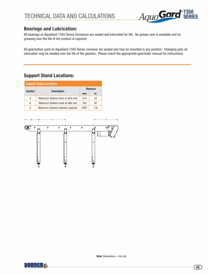
7350SERIESTECHNICAL DATA AND CALCULATIONS
Bearings and Lubrication:All bearings on AquaGard 7350 Series Conveyors are sealed and lubricated for life. No grease zerk is available and no greasing over the life of the product is required.
All gearmotors used on AquaGard 7350 Series conveyor are sealed and may be mounted in any position. Changing gear oil lubrication may be needed over the life of the gearbox. Please check the appropriate gearmotor manual for instructions.
Support Stand Locations:
Support Stand Locations
Symbol DescriptionDistance
mm in
A Maximum distance back at drive end 610 24
B Maximum distance back at idler end 762 30
C Maximum distance between supports 2997 118
Note: Dimensions = mm (in)
B C A
65
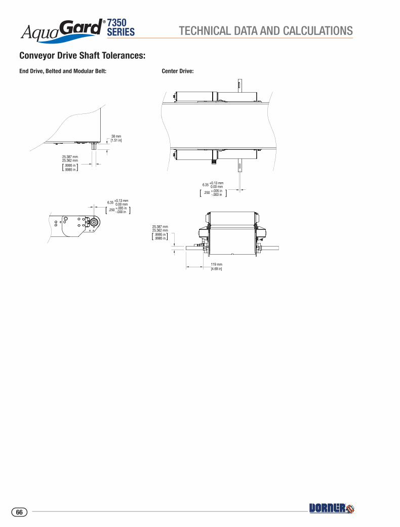
7350SERIES
119 mm [4.69 in]
38 mm [1.51 in]
6.35 +0.13 mm 0.00 mm
[ .250 +.005 in-.000 in ]
6.35 +0.13 mm 0.00 mm
[ .250 +.005 in-.000 in ]
25.387 mm25.362 mm
[ .9995 in.9985 in ]
25.387 mm25.362 mm
[ .9995 in.9985 in ]
TECHNICAL DATA AND CALCULATIONS
Conveyor Drive Shaft Tolerances:
End Drive, Belted and Modular Belt: Center Drive:
66
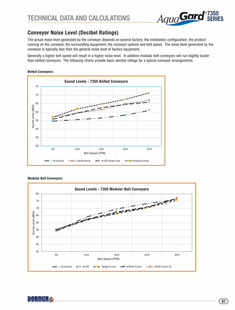
7350SERIES
40
45
50
55
60
65
70
75
50 100 150 200 250
Soun
d Le
vel (
dB(A
)
Belt Speed (FPM)
Sound Levels - 7350 Belted Conveyors
End Drive Center-drive LPZ Nose Over Positive Drive
40
45
50
55
60
65
70
75
80
50 100 150 200 250
Soun
d Le
vel (
dB(A
)
Belt Speed (FPM)
Sound Levels - 7350 Modular Belt Conveyors
End Drive LPZ Single Curve Multi Curve Multi Curve (2)
TECHNICAL DATA AND CALCULATIONS
Belted Conveyors:
Conveyor Noise Level (Decibel Ratings)The actual noise level generated by the conveyor depends on several factors; the installation confi guration, the product running on the conveyor, the surrounding equipment, the conveyor options and belt speed. The noise level generated by the conveyor is typically less than the general noise level of factory equipment.
Generally a higher belt speed will result in a higher noise level. In addition modular belt conveyors will run slightly louder than belted conveyors. The following charts provide basic decibel ratings for a typical conveyor arrangements.
Modular Belt Conveyors:
Sound Levels - 7350 Belted Conveyors
Sound Levels - 7350 Modular Belt Conveyors
67
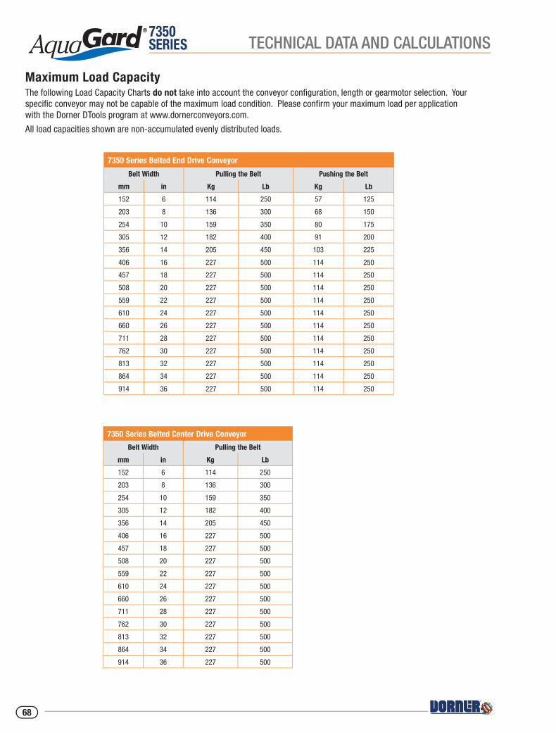
7350SERIES TECHNICAL DATA AND CALCULATIONS
Maximum Load CapacityThe following Load Capacity Charts do not take into account the conveyor confi guration, length or gearmotor selection. Your specifi c conveyor may not be capable of the maximum load condition. Please confi rm your maximum load per application with the Dorner DTools program at www.dornerconveyors.com.
All load capacities shown are non-accumulated evenly distributed loads.
7350 Series Belted End Drive Conveyor
Belt Width Pulling the Belt Pushing the Belt
mm in Kg Lb Kg Lb
152 6 114 250 57 125
203 8 136 300 68 150
254 10 159 350 80 175
305 12 182 400 91 200
356 14 205 450 103 225
406 16 227 500 114 250
457 18 227 500 114 250
508 20 227 500 114 250
559 22 227 500 114 250
610 24 227 500 114 250
660 26 227 500 114 250
711 28 227 500 114 250
762 30 227 500 114 250
813 32 227 500 114 250
864 34 227 500 114 250
914 36 227 500 114 250
7350 Series Belted Center Drive Conveyor
Belt Width Pulling the Belt
mm in Kg Lb
152 6 114 250
203 8 136 300
254 10 159 350
305 12 182 400
356 14 205 450
406 16 227 500
457 18 227 500
508 20 227 500
559 22 227 500
610 24 227 500
660 26 227 500
711 28 227 500
762 30 227 500
813 32 227 500
864 34 227 500
914 36 227 500
68
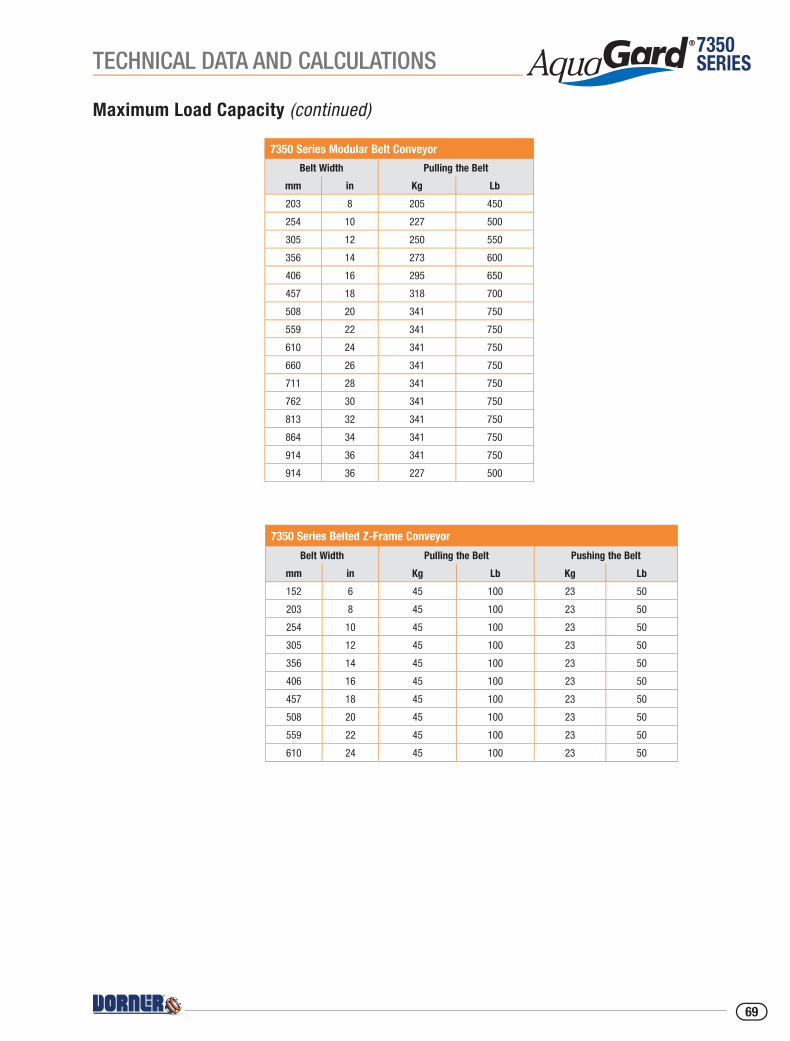
7350SERIESTECHNICAL DATA AND CALCULATIONS
7350 Series Modular Belt Conveyor
Belt Width Pulling the Belt
mm in Kg Lb
203 8 205 450
254 10 227 500
305 12 250 550
356 14 273 600
406 16 295 650
457 18 318 700
508 20 341 750
559 22 341 750
610 24 341 750
660 26 341 750
711 28 341 750
762 30 341 750
813 32 341 750
864 34 341 750
914 36 341 750
914 36 227 500
Maximum Load Capacity (continued)
7350 Series Belted Z-Frame Conveyor
Belt Width Pulling the Belt Pushing the Belt
mm in Kg Lb Kg Lb
152 6 45 100 23 50
203 8 45 100 23 50
254 10 45 100 23 50
305 12 45 100 23 50
356 14 45 100 23 50
406 16 45 100 23 50
457 18 45 100 23 50
508 20 45 100 23 50
559 22 45 100 23 50
610 24 45 100 23 50
69
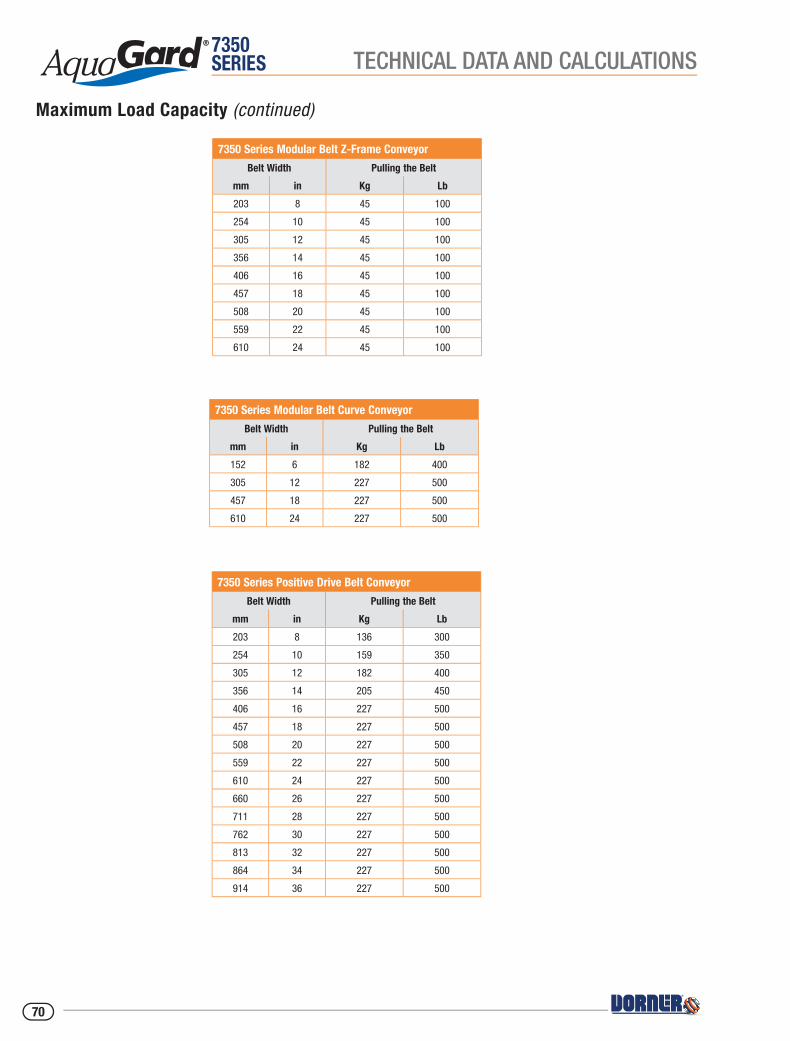
7350SERIES TECHNICAL DATA AND CALCULATIONS
7350 Series Modular Belt Curve Conveyor
Belt Width Pulling the Belt
mm in Kg Lb
152 6 182 400
305 12 227 500
457 18 227 500
610 24 227 500
7350 Series Modular Belt Z-Frame Conveyor
Belt Width Pulling the Belt
mm in Kg Lb
203 8 45 100
254 10 45 100
305 12 45 100
356 14 45 100
406 16 45 100
457 18 45 100
508 20 45 100
559 22 45 100
610 24 45 100
7350 Series Positive Drive Belt Conveyor
Belt Width Pulling the Belt
mm in Kg Lb
203 8 136 300
254 10 159 350
305 12 182 400
356 14 205 450
406 16 227 500
457 18 227 500
508 20 227 500
559 22 227 500
610 24 227 500
660 26 227 500
711 28 227 500
762 30 227 500
813 32 227 500
864 34 227 500
914 36 227 500
Maximum Load Capacity (continued)
70
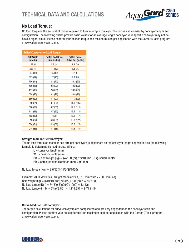
7350SERIESTECHNICAL DATA AND CALCULATIONS
No Load Torque:No load torque is the amount of torque required to turn an empty conveyor. The torque value varies by conveyor length and confi guration. The following charts provide basic values for an average length conveyor. Your specifi c conveyor may not be have a higher value. Please confi rm your no load torque and maximum load per application with the Dorner DTools program at www.dornerconveyors.com.
Straight Modular Belt Conveyor:The no load torque on modular belt straight conveyors is dependent on the conveyor length and width. Use the following formula to determine no load torque. Where: L = conveyor length (mm) W = conveyor width (mm) BW = belt weight (kg) = (W/1000)*((L*2)/1000)*8.7 kg/square meter PD = sprocket pitch diameter (mm) = 99 mm
No load Torque (Nm) = BW*(0.3)*((PD/2)/1000)
Example: 7350 V2 Series Straight Modular Belt, 610 mm wide x 7000 mm longBelt weight (kg) = (610/1000)*((7000*2)/1000)*8.7 = 74.3 kgNo load torque (Nm) = 74.3*0.3*((99/2)/1000) = 1.1 NmNo load torque (in-lb) = (Nm)*8.851 = 1.1*8.851 = 9.77 in-lb
Belted Conveyor No Load Torque
Belt Width mm (in)
Belted End Drive Nm (in-lbs)
Belted Center Drive Nm (in-lbs)
152 (6) 0.9 (8) 7.9 (70)
203 (8) 1.1 (10) 8.6 (76)
254 (10) 1.5 (13) 9.2 (81)
305 (12) 1.7 (15) 9.9 (88)
356 (14) 2.3 (20) 10.2 (90)
406 (16) 2.3 (20) 10.2 (90)
457 (18) 2.8 (25) 10.5 (93)
508 (20) 3.1 (27) 10.9 (96)
559 (22) 3.1 (27) 11.2 (99)
610 (24) 3.4 (30) 11.9 (105)
660 (26) 3.7 (33) 12.5 (111)
711 (28) 3.7 (33) 12.5 (111)
762 (30) 4 (35) 13.2 (117)
813 (32) 4.3 (38) 13.8 (122)
864 (34) 4.3 (38) 13.8 (122)
914 (36) 4.3 (38) 14.8 (131)
Curve Modular Belt Conveyor:The torque calculations for curve conveyors are complicated and are very dependent on the conveyor save and confi guration. Please confi rm your no load torque and maximum load per application with the Dorner DTools program at www.dornerconveyors.com.
71
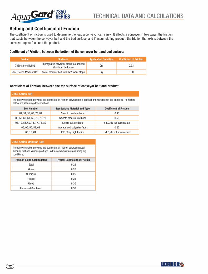
7350SERIES TECHNICAL DATA AND CALCULATIONS
Belting and Coefficient of FrictionThe coeffi cient of friction is used to determine the load a conveyor can carry. It effects a conveyor in two ways: the friction that exists between the conveyor belt and the bed surface, and if accumulating product, the friction that exists between the conveyor top surface and the product.
Product Surfaces Application Condition Coefficient of Friction
7350 Series BeltedImpregnated polyester fabric to anodized
aluminum bed plateDry 0.33
7350 Series Modular Belt Acetal modular belt to UHMW wear strips Dry 0.30
Coeffi cient of Friction, between the top surface of conveyor belt and product:
7350 Series Belt
The following table provides the coefficient of friction between steel product and various belt top surfaces. All factors below are assuming dry conditions.
Belt Number Top Surface Material and Type Coefficient of Friction
01, 54, 58, 68, 73, 81 Smooth hard urethane 0.40
02, 59, 60, 61, 66, 72, 76, 79 Smooth medium urethane 0.50
03, 19, 55, 69, 75, 77, 78, 80 Glossy soft urethane >1.0, do not accumulate
05, 06, 50, 53, 63 Impregnated polyester fabric 0.20
08, 18, 64 PVC, Very High friction >1.0, do not accumulate
7350 Series Modular Belt
The following table provides the coefficient of friction between acetal modular belt and various products. All factors below are assuming dry conditions.
Product Being Accumulated Typical Coefficient of Friction
Steel 0.25
Glass 0.20
Aluminum 0.25
Plastic 0.25
Wood 0.30
Paper and Cardboard 0.30
Coeffi cient of Friction, between the bottom of the conveyor belt and bed surface:
72

7350SERIESTECHNICAL DATA AND CALCULATIONS
Calculating Conveyor Load Capacity
There are several factor that effect the overall conveyor load of AquaGard 7350 Series Conveyor. These include:
• Conveyor size and confi guration
• Conveyor speed
• Application temperature
• Product accumulation
• Number of starts and stops per hour
Located online at www.dornerconveyors.com is the Dorner conveyor confi guration tool, DTools. This tool allows you to confi gure your conveyor layout and determine the maximum load capacity for the conveyor. It is suggested that this program be used to calculate the conveyor load as the calculation is quite complicated. This confi guration program however does not take into account temperature, dirty conditions, and conveyor starts and stops. If these conditions are part of your application please use the load reducing factors as shown below.
Maximum Load = (Load from DTools)(Temperature Factor)(Start/Stop Factor)
Temperature Factor
Ambient temperature can negatively affect the capacity of the conveyor.
Temperature F Temperature C Temperature Factor
-4 -20 1.0
32 0 1.0
68 20 1.0
104 40 0.9
140 60 0.8
Start / Stop Factor
Frequent Start / Stops of the conveyor can negatively affect the capacity of the conveyor. All start / stop applications must use a soft start mechanism such as a Frequency Inverter with a 1 second acceleration cycle.
Application Condition Start / Stop Factor
Continuous Run or 1 start/stop per hour 1.0
Maximum 10 starts/stop per hour 0.83
Maximum 30 starts/stop per hour 0.70
Greater than 30 starts/stop per hour 0.62
73

7350SERIES
Calculating Conveyor Belt Speed:
AquaGard 7350 Series Conveyors:To calculate the conveyor belt speed you need to know the following factors:
DR = Drive roller diameter or drive sprocket pitch diameter (mm)
= 89 mm (3.5 in) for end and center drive belted conveyors
= 99 mm (3.9 in) for end drive modular belt conveyors
= 99 mm (3.9 in) for end positive drive belt conveyors
TD = Number of teeth of pulley located at drive roller (if equipped)
TG = Number of teeth of pulley located at gearmotor (if equipped)
RPM = Revolutions per minute of gearmotor
Belt Speed (m/min) = RPM*(TD/TG)*(DR/1000)*3.14
Example:AquaGard 7350 Series Belted End Drive, bottom mount with a 36 tooth pulley located at the drive roller and a 30 tooth pulley located on the gearmotor. The gearmotor is a 10:1 ratio with 173 rpm output.
Belt Speed (m/min) = (173)*(36/30)*(89/1000)*3.14Belt speed (m/min) = 58 m/minBelt speed (ft/min) = 58 m/min*(3.28) = 190 ft/minNo load torque (Nm) = 74.3*0.3*((99/2)/1000) = 1.1 NmNo load torque (in-lb) = (Nm)*8.851 = 1.1*8.851 = 9.77 in-lb
TECHNICAL DATA AND CALCULATIONS
74
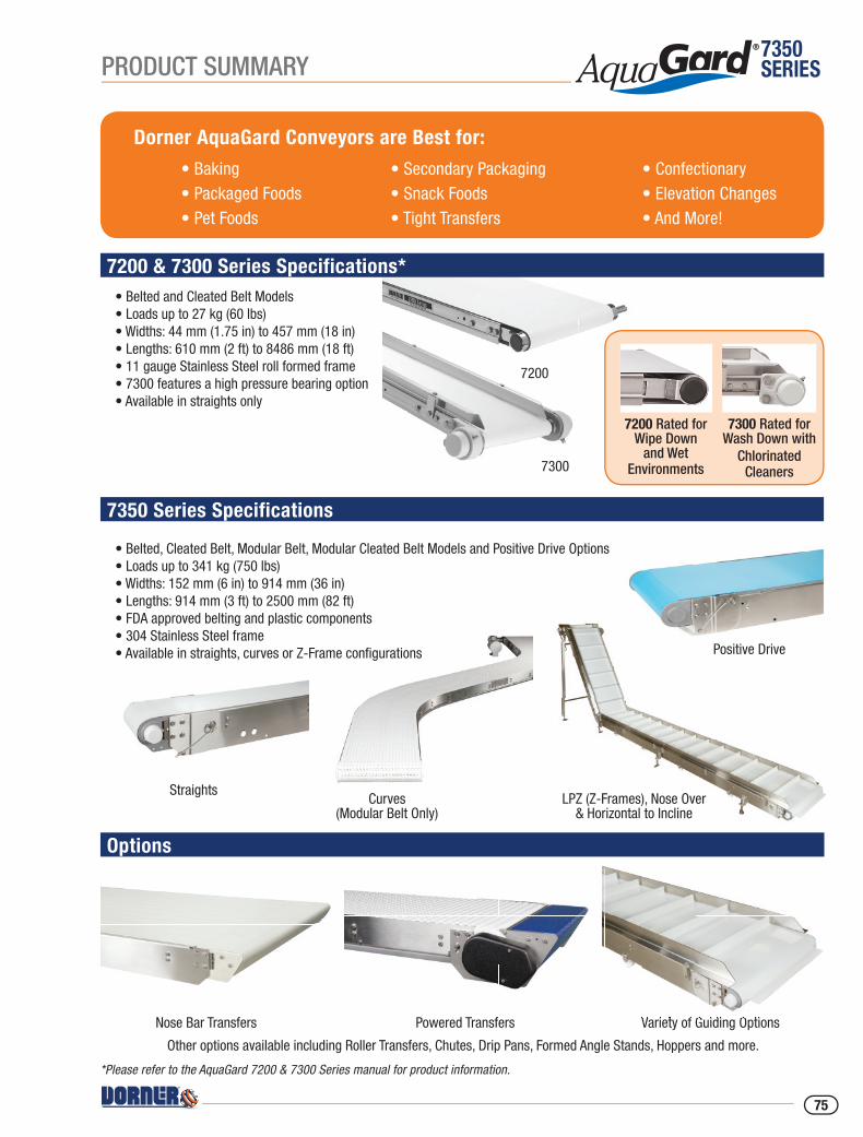
7350SERIES
*Please refer to the AquaGard 7200 & 7300 Series manual for product information.
7200 & 7300 Series Specifications*
Dorner AquaGard Conveyors are Best for:
• Baking• Packaged Foods• Pet Foods
• Confectionary• Elevation Changes• And More!
• Secondary Packaging• Snack Foods• Tight Transfers
7350 Series Specifications
Options
Straights
• Belted and Cleated Belt Models• Loads up to 27 kg (60 lbs)• Widths: 44 mm (1.75 in) to 457 mm (18 in)• Lengths: 610 mm (2 ft) to 8486 mm (18 ft)• 11 gauge Stainless Steel roll formed frame• 7300 features a high pressure bearing option• Available in straights only
• Belted, Cleated Belt, Modular Belt, Modular Cleated Belt Models and Positive Drive Options• Loads up to 341 kg (750 lbs)• Widths: 152 mm (6 in) to 914 mm (36 in)• Lengths: 914 mm (3 ft) to 2500 mm (82 ft)• FDA approved belting and plastic components• 304 Stainless Steel frame• Available in straights, curves or Z-Frame confi gurations
Curves(Modular Belt Only)
LPZ (Z-Frames), Nose Over & Horizontal to Incline
Nose Bar Transfers Powered Transfers
Other options available including Roller Transfers, Chutes, Drip Pans, Formed Angle Stands, Hoppers and more.
7200
7300
7200 Rated forWipe Down
and Wet Environments
7300 Rated forWash Down with
ChlorinatedCleaners
Variety of Guiding Options
Positive Drive
Variety of Guiding Options
PRODUCT SUMMARY
75
10YEARWarranty
Transforming Conveyor AutomationIndustrial & Automation Conveyors
Sanitary Conveyors Engineered Solutions
Online Confi gurator
© Dorner Mfg. Corp. 2018. All Rights Reserved. 851-895 REV A 0918
WarrantyParts Service
Dorner – North & South AmericaDorner – U.S.A. Headquarters975 Cottonwood AveHartland, WI 53029, USA(800) 397-8664(262) [email protected]
Dorner – Canada100-5515 North Service RoadBurlington, Ontario L7L 6G6 Canada(289) [email protected]
Dorner – Latin AmericaCarretera a Nogales #5297, Nave 11. Parque Industrial NogalesZapopan, Jalisco C.P. 45222 México+52.33.30037400 | [email protected]
Dorner – EuropeKarl-Heinz-Beckurts-Straße 752428 Jülich, Germany+49 (0) 2461/93767-0 | [email protected]
Dorner – Asia128 Jalan Permatang Damar Laut, Bayan Lepas 11960 Penang, Malaysia+604-626-2948 | [email protected]
www.dorner.com