730 TRANSMISSION MONITORING - IET Labs a … Assembly From 512-A.pdf · CLASS 730 TRANSMISSION...
12
CLASS 730 TRANSMISSION MONITORING ASSEMBLY GENERAL RADIO COMPANY CAMBRIDGE, MASSACHUSETTS NEW YORK LOS ANGELES U. S. A.
Transcript of 730 TRANSMISSION MONITORING - IET Labs a … Assembly From 512-A.pdf · CLASS 730 TRANSMISSION...

CLASS 730
TRANSMISSION MONITORING
ASSEMBLY
GENERAL RADIO COMPANY CAMBRIDGE, MASSACHUSETTS
NEW YORK LOS ANGELES U. S. A.
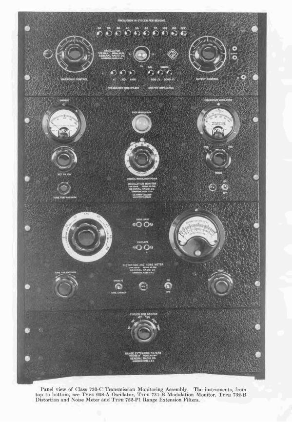
1';tncl rFww of C1;~sa 750-r Tmnstnission Monitoring Assembly. The instruments, from top t o hottom, are Tu1.1.: fiO%?t Orcillatnr, 731-I3 5Torlitlntion Monitor. TYPE 732-I$ 1)istortinn nnrI Noiw Meter nmrl TYPF; 732-Pi l t a n p Extension Filters.

INTRODUCTION It is well recognized that tlie n~nxin~urn opcr:ding eficienry of a broadcasting transmitter
rannot he rcadiIy attained without the use of proppr ~nr:~suring np1):~ratus to wide tlie er~ginepr in his arljtistnient of the rrluipment. :4II too often the rapal>iliti~s of n transmitter nrc not utilized to their fullest extc~it hecause t l r r cxis-ting ro~~rlit ions are uat knawn. J Imy times, ton, if, Fins b e ~ n assmned that, hec~tusc the I>mndc;~st erft~ipnlrnt is n l well-known and reliable mnnufi~ctr~rc, it cont.ini~~.; to operate mo~ith alter ~ l ~ o n t h with the WIIIP d~gwe of 6~4e)ity as it did when originally inxtalIt-d and adjusted.
Experience h;~a provtld t h p t~sefulness nf trip modiflxtiort monitor and distortion rnc:~suring ~r[uipn~t*nt ~ ~ i t h all typ.; anrl makcs of hrnadcast ir~~ tr:rnsrnitters. It 1r:is hcen fount1 tha t tl~r cryreration of even the F~rst tranqmitters Iltay he srriously ilrlpairtrd 1)rr:iuse of slight misadju~tr~ients, failing w c ~ u ~ n ~ tulles, or othcr fitultp circuit elements.
ti modtilation monitor is reqnir~d in every lTnitrd States hrn~dcnsting station, hy the rcq1:itions of tile F~dernI Commnnicn tions Commission, :I nt1 ;I. wrt nin :I moril~t of m~asurin~f equipnlent is in llsr in a11 statiorlc, 1~ilt tlie drtrrrninntintl of pcrrrntahv dintorlion, carrier noise and huni ICVPI. etc., is not nlmeps ~irtd~rtakcn as routirle maintcnance. To a c~rtnin extent tlii4 o~wrating procedure hrr s 1lrc11 j11rt ifird hcc:tuse af the laclc of suikr l ~ l e nreasl~ring equipment and hccai~sc of the favt that , pner:11Ig upraliing, thy rxrlio-transmitting systenl %-as ronsiderab4y l~ r t t e r than thc rrceiving system. 'Flie rapidly increasing intcrrst in so- called Iiigh-fidrli ty rer~ptivn and the :tppe:tr~ncr ot receiving sr t c; c:cl,ahle of fnithfnl rpproduct ion 11~\-c plered :I &finite rc.iponsihility 111)ori the hrondmstcr tn 1nxint:iin h is station in tlie wry lwst operating rendition. This sitrlation i s W P I P recognimd 1)s nmmt broadcast engineers.
Tlie eqriipnlent cle~crihcd in this hullctin lins been r!rsignrd .iprcific:~lly .For uqe in hroxd- ensting stations. I t is rcasonnl~ly priced, accurate, easily inst;rlletl, and simple to nprmtc. J t, is a-c operatecl and wlny-rack nlountcd, and all qrr:tntities lindrr mc:lsurement arc indic~atcd 011 dirtct-wading meter.
Two arranprnentq :irr arailnblc, the one providing x sing1:lr (listortion rnensurrmrnt n t 400 cycles. ar~tF the o t h r providing mensurcmrnt~ ;it the six frcrrttencics in the nudio- frequency s p c t rum.
Distortion mcasuremcnts wit11 file Class 733.0-B Tr:~nsmis<ion JZonitoring .isrclnhly are made :tt the test f r ~ q i ~ r n r y of 1(10 r y r l r s :~nd 1l:lve prtr.r.cld tn br cstl.cnlrly i ~ ~ f u l for tr:~rts- mitter rnnintenancr. For thv k~st rrsultq, howc~er, distnriinn r n e ; ~ s ~ ~ r e r n ~ n t s arv prefer:~hly made at sevrml test lwqt~~ncies rr-rll spacrr l in the nrlilio-lrtqi~ency 1,:ind. The 11. S. FecleraI Co~nrnunicat~ions C'onilniasion rcrornn~ends test frctl~~cr~cies of 50, 100, 4lM, t Ol)!l, 5F100 and 7300 rycIcs. Thew are cowred l ~ y tlre Class 730-C Transnlisrion JIonitoring Asernblp,
The Class 7.50-l3 Transmission Jronitnring Assembly ccnnsi.it5 nf t 11rrc nnit s: {I) rnotlu- Irttion meter and over-modtllation indicator, (2) distortinn and noise meter, (3) 400-cycle oscillator. Briefly, the equipment is capable of memuring:
I. Percentage modulation on both positive and negative peaks. R. Progam monitoring with high-sped volume indicator meter. 3. Carrier shift upon the application of modulation. 4. Carrier noise and hum level. 5. Combined audio-frequency hartnortic distortion of modulation enveIope (measwred
at 400 cycles).

ti. 3 tndiilntir~n ]u*ii k'i rsrrrrling :L prctLtrrnrinrd, desire11 rl~gree of morlulat ion (i.e. ovrr-ntotlul;~? ion intlic-;itor).
7 . Vuml)inrd ;iudin-frPqlirncy I~:irmotlic diritortion (~?enslrrrd :~t 400 cycles) ~ ~ r c s e n t in speecll-irlp~t arliplificr ;In11 other station rrluipnlent.
R. Eoiar nnrt r'r~rm I P \ T ~ of anclin nlnplifi~rs nntl othrr station ecl~l i l~~~lel l t , including wirr lines t o ~.rmotr* pit'k-up points :mtI to trancmittcr.
The altcrnntc. systrrn. C'l;~ss 'if{(!-C Tr;l~l.;rl~i.qsion Rfnnitnring : \ s ' ~ c I T I ~ > ~ ~ providrs for dis- tortiem mrhnsllrrmmtr; : ~ t 50, ]()(I. -1.00, 101)0, 5000 ant1 7300 cyvfcs. I n :tdtlition to tlte r~or 1ul:lt inn nlo~litor : ~ n d tlw tlistoriirri~ :tiid nnisr nlrtcr, this nsseiilldy int.luc1cv (1 ) nn
:~urlin-Frrqilrnrq. r,stbill:ttor s ~ ~ l ~ p l y i r ~ g ;I 111.111ilwr OF fixrd freq~icn~'ics, and (9) :an nuxilinry filltar pnnrl tr~nt:tining iiltrbr'i for tllc :~dtlitinnnl frcy~rcnrirs,
IYitlt t lrc mu1 ti-frPy 1rrnt.y nutlic~ ostbillator, it is also posril~lc to measure :
9. Trnnsrnitter suclio frvcl11nic.y response.
In . Audio : ~ ~ n p l if er ;irlrl r t j z ~ i l > n ~ c ~ ~ t frrqucncy response.
1 1 , Wirr linr frerl~tcnry wsponsr.
Tlac. qi~:lntitiq*s ~nt.ns~~rcvl ; ~ r r marl clirrhttly from t Flc instrument, nnd no cn1rnl:it ions what- s w v r r :ire nPcvssXqF. N~i t hcr is it nrcrswrq- to rffect any difficril t nnd critical :~djustmerlts or ha lnnrca.
D u r i n ~ [ tcat s mnductrd 1 ) ~ 1,rondmst ~ n ~ i r ~ c c r s . the apparatus I~ns hecn uscrl t o detrrmine tllr r l~:~r : l r t~r is t i ts of various t y p s nf radio tritnsrrlittrss, ranging from 50-rv:itt, port;~lrlr. remotc pick-np trnnsmittrrs to 50,OnO-wntt I>roi~dr:~st tr t~ns~nitters, and :il'ic) on high- frrrluenry 1,rondcnst t r nnsn~ i t trr.; opcr:it in^: n t freqnencirs up to GO ~negacyclrs. 3l~aq1tre- t i~ents on audio eqlr i j)ml>nt :Ire nlcio 1)ossit~le with this cqliip~nent, and i t hrts hcrm trstrd nn ev~rything froln r ~ o r t a l ~ l e firltl amplifiers t o program amplifiers, line am plifters and pulllic atldr~ss ciluipn~ent.
Onrr the rqrripmrnt h:~s I ~ * c n insknllcd. i t is possil>b, in Icss t.llnn ten minutes, to mfilic n mrrlplrt~ rtln or1 ;I tr:~nsmittrr xlld t l e t ~ r ~ ~ l i n c thr pnsitil-e nnd n c p t i v e rnoilulntion pmks. the ~ ~ r c c n t ; i g ~ distortion sntl t l ~ c noisc or Illlrn level threughnut tile range of nndio input ~ I I P t r :~r~sni i t t~r i s czpnhle of Irandiing.
111 sorrle actt~al instanrcs, IT-itlt the air1 of dlis me:txuring equipment, ~ I I P posi t iv~ and negativc pcnks of n t rxr~sn~i t t r r ltavc lwen I~;~l;lnwd find tElr dist,ortio~t reducrd t o hnlT its r e I 1Yh:i t i s Inore important is t h r fact that, ns ,z result of tllese iniprovi~.r.nlmts, it i.i ~mw'il,lr to i11rrc-nse tFic progr:tnl input 1c.1-cI t o thc tm-nns~~~ittev quitr mnsider:~I,Iy wi tlloizt musing as mudl distort ion ns rsiqt cd before the arljustmmts were effected. \\'hen it ir c o n s i d ~ r ~ d tlritt an inrrrnrc in a d i n input lrvel of only 3 cl~ril wls resuIts in an incrr:~sed s i p a 1 i n t ~ ~ l s i t y : ~ t tllr listener's rnilio sct crluiralent to d o ~ ~ b l i n g the power of transmitter, the importance of surll int~)rat*erlrcnts is ollvior~s.
CInss $30-R Transmission Rlonitoring Assenihly consists of the following instruments: Prim
. . . . . . . . . . . . . . . . . . . . . . . . . . . . TYPE 731 -I3 3fodul:ttion 3fonitor. $1 95.00*
. . . . . . . . . . . . . . . . . . . . . TYPE i:.iJ?-I3 Distortion and Noise I I t~ te r . . 245.OO
..................................... Trrn '733-,I Osrillntor.. 64.00
2 - *Rcq~iirr.\l I r > ' thr 1.. q. Ftvl~tr~l ('c~tnr~%~rtr;c~lir~nq I'rrrnnli*~irlrt. T11v 'l:rw 731-H hn* FCC nppmrnf XI,. 7 i .il.
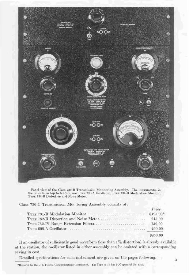
R ~ n r l vicw of the Clr~ss 7.50-R Transmission Mcr~~itoting ks~emhly. The instrum~nts. in t lnr orrlrr rrvln top to t)nttom, rlre ?'WE 7S:I-.\ osri1ialor, TYPE 731-I% >iod~~ lnt lon \lonitor, Trt,c f:lr?-1% ni.sturtion nntl Noise Meter.
Class 730-C Transmission 3Ionltoring :2ssemhly mnsista of : Prirs
TYPE 731-l3 3fodlllntion Monitor. . . . . . . . . . . . . . . . . . . . . . . . . . . . . *I D.i.00* TYPE $32-TI Distortion and h-0i.w Meter.. . . . . . . . . . . . . . . . . . . . . . 245.00 TYPE 732-Pl Range Extension Filters. . . . . . . . . . . . . . . . . . . . . . . . . r :jO.nn TYPE G08-;1 O~cillator. . . . . . . . . . . . . . . . . . . . . . . . . . . . . . . . . . . . . . . OtiO.O(l
If an osrillator of sufficiently good u-aveform (less than I r ; distortinn) i*; :tlrc;ldy nvitil:~ble at the station, the oscillator 1istc.d in e i t h ~ r assembly can 1 ) ~ omitted with n mrrrsponding saving in cost.
DetailcrI apccifirntions for e:tch i n s t r u m ~ e ~ t are given on tlie pnges followir~g. . a
p-
*Requrircd Iry the fi. S. Fderal Cornm~rnicntinns Cornmisrion. The Tyw 731-R ha FCC ~~pprov;tl No. 1551.

.i ('lxsq 740 Trnnn- mission M o n i t r ~ r i n ~ ~lssentbly in use i r ~ a hroatlrasting st:)- tion. Tlie op~rrctnr is sl~ov 11 F I S ~ ~ I R t l i ~ rnod~~lation monitor.
TYPE 731 -0 MODULATION MONITOR
USES: T11c modulation nionitnr is lisrd t o TerrninaIs are provided so that remote Incxsurc and tr, indirntr mntintlausIy t l ~ r percentage modulntion indicatnrs or over- percentage mmoduIatinr~ or hroadcnst and modulation indicator lamps can he cnn- other mrlio-tplepl~one tmrlsmitttrs. It n ~ ~ e t s nected to the instrr~mrnt externally. Pro- the rrqr~irrnicnts for rnoilr~latir~n monitors vision is also alade for connecting n peak specifirri in Rule 139, nn~entlrti. OF the Fd- counter or a recordrs. The rncdulation era1 Conlm~~nica t ions Commission. IF has monitor mil1 opmtc at frrq~tencies hcturern heen approved h p the Cornrnisqion and 0.6 llIc and 60 M c . 'rw-l-o sets of plug-in roils assignccl Apprclvd KO. 1551. are used to cover t he compkte range. Onc
Thc fnllon Infi spwific nlrasur~mtnt s can sr t is supplier! with tlrc instrument. he made with flie TYPE $:<I-I3 Alorlitlntinn The meter r~rhicli wads modulation per- nIanitor: mntnge has a h i g h - s p ~ d movement. Tt is
1. Rteast~rcment of pcrc;.ntage motluln- used in conjl~nction with ~lertricnl delay tinn nn rither positive or negntivc pmks. circuits to give a mpid npsming and a slower
2. I+rclcram level monitoring. rptnrn. 3. 3I~;ulsrement of carrier shift when The flashing lamp is extremely ttneftll as
modulation is applied. a monitoring device. Tt is set to flash with 4, Jnrlicat ion of moduIation peaks exreed- moder:tte frequency when the transmitter is
in^ a predetermined degree of modulation operating norrnnllq.. If thc flmhing rate (imp,, 0.r-er-modulation indicator). rhnngcfrs marked!?., the opr.r~tor is made
5. Transmitt ~r aildin-frerjnency response. aware that sornrthing is wrong.
DESCRIPTION: TYPE 731-R hiodulation fitonitor consists nf three essential elements : I ] ) a linear diorle r~r t i f ier which g i v ~ s an instantaneous output voltage proportional to the carrier env~lope, (9) a peak voltmeter which g i v ~ s a cont inuo~~s indication of the peak modulation. and (3) a trigger circlrit which Rashrs a light w l ~ e n e r ~ r the modula- tion nlon~antarily exccrds any value wl~ich has b e ~ n previously set hp t11c oprmtor.
En the output of tlie linear rectifier is R
d-c meter which indicates the carrier Icvel at which the ins\rument is operating and also shows any c ~ r r i c r shift during modtiln- tion.
FEATURES: Speed and simplicity of opera- tion, rsscntinI for monitoring i r ~ s t r r ~ m ~ n t s , are avnilzihle in this instrument. It opcrntrs over a wide cnrri~r-frequency range, and a t u n ~ d input circuit is provided t o facilitate conpling to t11e transmitter.
The biasing circuit which controls the operation of the over-modulation indicator is so designed that the accuracy of the lamp is entirely indepndent of shifts in carrier amplitude.
The type of movement used in the direct- rending meter is extremely easy to folIow with the eye and is the most satisfactory thus far devised.
PEAKS DIODE + - V.T. VOLTMETER -
R.F.
GAS- DISCHARGE TUBE
MODULATION PEAKS LAMP
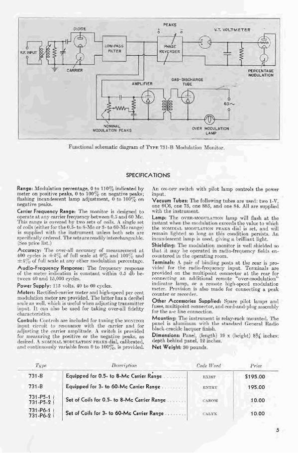
Functional schematic d i a ~ m of TYFE 791-8 Xinrlulntion >Ionitor.
SPECIFICATIONS
Range: 3fodulation percentage, O to 110% indicated hy metes on positive pcnks, O ta 100% on n e ~ a t i r c peakx; Hashina incnndpsrent lamp adjustment, 0 to 100% an negative penb. Carrier Frequency Rmnqe: The monitor is rlesignd to nperat? a t rlriy carrier frequrmcy hetn-een 0.5 anti tWl Arc. T h i s sntljie 1s mvertrl hy two *sets of coils. A sin& .wt nl roils (cit her for the 0,s- to 8-ITc or 3- to RO-3lc rangc) is supplier1 n'itl~ the inatsltment u~nlern hot11 sets are rpecihcally orrIere(1. Tile setsare rentlily intert~hanjiea1)lc. (Set. prirhr list.) Accuracy: The over-all nccumcy OF measurement at 4n(l ryrleq is *Qo",f full wale a t 0% nnci 1.00:; nanrl
uuf full scnle xt nny other modulation perrentage. Audio-Frequency Response: The lwquenry response nf tlie r n e t ~ r inrticntion is constant nitllirl 0.5 dl, be- trr.cr11 40 nrtrl 15,000 cycles. Power Supply: 115 volts, 10 to RR cycles. Meterr: Ilectifi~(I-rnrrier meter and high-speed per rent irlr~rl~!latinn intatrr are prnvirlerl. Tlw lntter hns a dprihel SP:I ir ns well. n lilch is uwfu1 allen adj~isting trsnstnittrr inptlt. I t ~11x1 nlsn I IC used for tnkirig over-fill firl~lity rlinrllc.tr.rirtica. Controlr: Cnnlrnls an: inclutled for t r ~ n i n ~ the voxrrrm illp1~1 rlrvulit 1(1 T I F U I ~ ~ I I I L Y nit11 the alrrier and Frjr ntljitsting tlw mrrict ~tny)liturlt.. A switch is prnvirlerl for ~nensuring the positive or the negative peaks, desired. .% sornuhl MODrL4TIQY PsaKs dial, crrlibratecl. nru1 crr~tiniior~sly mriahle frorn 0 to 100%, ?is provided.
A n OW+W su-itch ~ i t h pilot lamp controls the power input. Vacuum Tubea: The Following tubes am oserl: two 1-V. one fjCF, on(! 75, one RH5, nnd one 84. AIl are supplied n7ith the instrl~nlent. Lamp: Tlic OI'ER-~~OI)FL~TIOX Tamp mill flnsh at tllc i n ~ t s n t when thc morlulntion exceeds the value to whicl~ the ro5rrsnL \mnl+tAT1ox m k R a din1 is set, and 11-ill remain liqllterl sn long as this mrlrlition pemi~ts. Art Iarar~rlescent lamp is t~e r l , givinfi s brilliant light. Shielding: The lnodnlntion monitor is ncll shielrIetI so tl~:lt ~t IIlay he op~rntrrl in radio-frequency frlds en- njuntrrerl in the npernting mom. Terminals: 4 pair nl bincling posts at the rear is pro- virleli For tlre ra<lio-fr~quency inprlt. Terminals are provirlcrl nn the multipoint mnnertor at the re-~r for rnnilecting an additional remote "o\prr-morli~lrtion" intlirntnr lamp, nr rcrnotr! high-speed moalulntion meter. finvisitm is aha made for cwrlnccting a peak muinter or remr~ler. Ofher AccessorFer Supplied: Spare pilot Inmps nnrl JU~PC, rnuItipoi~it wnnw tnr, nil11 mrrrL-at1(1-pl!1g a.csernl~ly for the a-c line mnnet.tion. Mounting: The instrument is relaprack mounterl. The 1);1rlrl is alutrtinurn 1vitF1 tllp ~ t ~ n r ! ~ r d G~nern l Qnrlio black-crackle lacquer finish. Dimensions: Panel, (length) 19 x (height) 8% inches: tEepth bcl~ind panel, 18 inclles. Net Weight: 50 pounds.
- --
731 B / Equipped lor 0.5- to 8-ME Carrier F!;nge . , . .
731 -8 ( Equipped lor 1- b M)-Mc Canicr Range
::;::::: I 5.1 01 Coils for 0.5- to 8-Mc Canirr Rango
::l:R:i I 1 Set of Coils for 3- 10 6 0 . M ~ Carrier Range
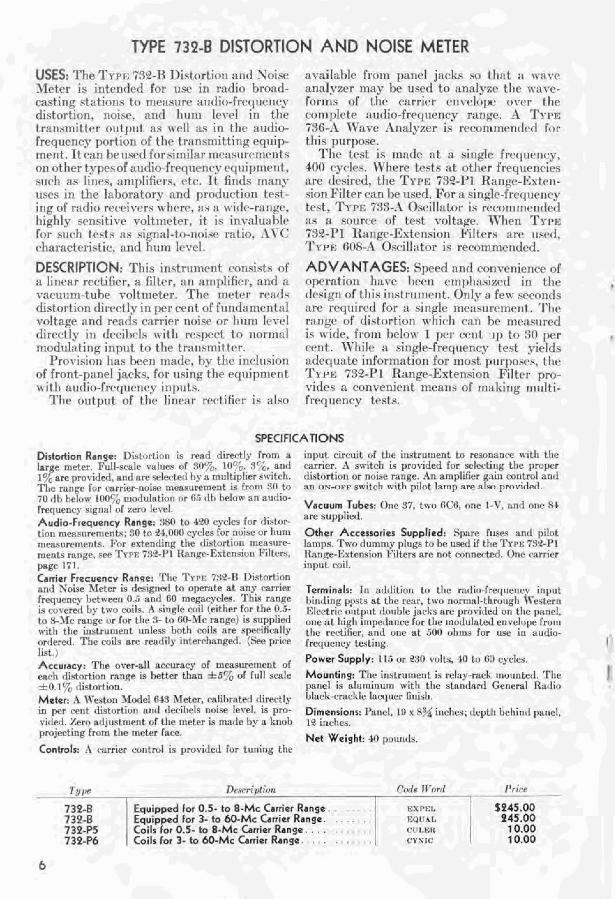
TYPE 732-8 DISTORTION AND NOISE METER USES: 'She TPPC T X - l 3 Distort i~b11 nncl Xniw Jlcter is intrilclc4l fnr use in rnrlio hrnnrl- c:tsting stilt intis t r t rnc:Istiw ai~dirh-frrq11rnr.y distort irrn, noise, nrlrl hnm 1v r r~ I in the t rnns~ni t tpr r)utllrlt : ~ s ~ ~ 1 1 :IS in t l ~ c nutiio- freqncncy portion of the Zrrlnsnlit tiny: e q ~ ~ i p - m ~ n t . It rorl hr used frlr<imi!nr r n ~ : ~ s ~ i r ~ r i i c n l ? ; rill other fyprcof :uldic,-f rrq11rnc.y c c ~ ~ ~ i l ~ n ~ r r ~ t , . ~ U C ~ I as l i ~ I P S . amplifiers, r+r. it i i r ~ r l s rti:tny IISPS ill the Ix1,oratnry nnrl pmrlirrtiun t ~ 4 i -
i r ~ g of r:ldio rt.c.c~ivtlrs rvhrrr. :IS :I n-i tl~-ritr~gc. l~ighly srnsitivc v o l t n ~ ~ t r r , it is invnlt~:~l)lr Inr such tppts ;IS ~;igrlal- to-~oiw ratio. .\I-(' r.l~arart~~.istit:. ant! h t ~ ~ n I t ~ c l .
DESCRIPTION: This in<triinlcnt cwi~is t . . ; of :L linear rrrtifirr, a filtrr, a n nmplifirr, n l ~ d n v a r a ~ ~ t n - t u b e voltlrlyt tv. 'Thr ~ n r t ~ r rc:~rls tlistortinn rlimct I F in p r cent of F~inrl:~mcrlt;tE voltape nnci rrxrir ~ : ~ r r i ~ t ' ~ioise or l111nl Irvt~l rlirectly in d e r i b l s with rrsprct tn itr~rnl:~l n~nditl:~ t i11g inp11t to ~ I I P t r n r ~ w ~ i t trr.
l 'rnvisin~~ Ii:is ~ P T I ~natlr, by f I jr inrluxirln of front-panel jacks, for using the etpipnlrnt wit11 audirl-fr~cl11rnt.4. inp~i ts .
T h e n~ttlitit 0% tlir linrttr r r (+i f i~r i~ alsn
availahlc from panel j:icks so t 11:1t :L I I - ~ I - ~ ~
analyzer may hr urcd to a n n l y a ~ tile (Tiire-
Fctrrlls of tlw r:irri~r c n v ~ l o p t ~ o w r t h ~ con~plrte nt~rlio-frt*c~r~c.r~cy r;inky. ;I TYIT .j:ZG--1 IVnc-f: ~ lnalyxcr is ~ ~ r c o n ~ r ~ ~ ~ n c l c r l for i11iq pi]rposc.
Ti le test is rnnde n t a single frcq~irncy. 400 cyvlrq. err tests a t n t l ~ c r freql~.ctic*ir!s ;Ire t fr..;ircd, tl te TYPE 739-1'1 IE:i~~g~-l:xte~r- sinn Fil t ~ r ran Iw u.icd. Fnr :I s in~ l t -~r .cr t l s~r lrv- i ' r~(~ i~~~~~y
trst. TYIXE 7:FL.I Oscil \ ;~tor is rrrnn~rnrndctl :IS n so111.w of tcwt 1-oltnget.. \Ylien T r r w 1!P2-P1 l t ~ n ~ ~ - E s f e ~ ~ s i o ~ ~ Pi! t ers nrr ~ i s t ~ l . ~ ' Y I = F ; G O x - , i (4scill:itor is ret~r~mmcr~rIatl.
ADVANTAGES: Slserd nntl convrnieriw or opvrnt ion 11ilvt' J I P C ~ empI1;~sixrrl in the drqign of this i ~ i s t r n n ~ r n t . 01114. :I fvw srmntl< are rrqriirrrl for ;i singlc ~ ~ c * : ~ s t ~ r c ~ ~ ~ e n t . The r:lncy c ~ f ~ i i~ t th r t ion wl~ir*l~ r:i 71 htl I I I ~ ~ : L S ~ I W C ~
is wirEe. from l~rlott- 1 per. rent 1111 to :10 Ibcr crnt. ll'hile a single-fr~rtuenry tevt yirlds :I t l~c ln;~ te inforrnntfnn for ~no.;t pillnpnsex, t l ~ c Tr11c 732-1'1 R:~nge-Extension Filter pro- vidrs a ronvenirnt meanti nf milliing ~ n ~ r l t i - fwq rlencp tests.
SPEC l FICATIONS DistortCon Range: Distnrtion ir rmd dimtly rrom a input circuit of the inrtru~oent to r w n n n c t mtl) the large rnrtrr. Full-stale vslup.9 of 3 0 5 . Ilb1>, st-;, nnrl mrricr. ;i switch is provideti Ivr selecttrl~ the proper 1'7, are pro~itIed. and arc seler-terl by a rnultipfier sn itch. tliclurtion or noke rnnge. :{R amplifier gain corltrrd nrld TIre mnpp fslr rsrricr-noiw naefinrarPmeut is fro111 XI! to :In nu-nvr switch n.i(I~ lxrnp nrp x1u1 prnvirlrrl 70 rlh ~ I P I O R . 1IDR';b ~uorlulatinn rlr (ii {l't) helow an aur!io- f rer luenq signnl of 7enl level Vacuum Tuber: One 37, two BCR, nne 1-V. nntl one RI
Audio-Fquency Range: :{Ha t o 4 9 cycles for difltor- arc supplierl. tion meacrlrerucnts: ::C) to * $,llor) cycles for noim or Ilum Other Accessories Supplied: Sp~re fusw anti pilot mras~~remcnts. I.hr eutentliri~ the tlistortirlr~ mektlllre- lai~tps. Two durnn~y plug+ to he userl i f the Tt-rb: 753-P1 rnents rarrgt=+ SPT TYI*I: ;'I?-!'I I ~ F I ~ ~ K F F ~ ~ P I I Q ~ R R Filt~rq, Ftarlge-lahtension Filters re not cor~nwtcd. Onc carricr page 171. i11p11l tvi!. Carrier Fteauenev Rnnqe: The TYPE 738-R Distortion nnal %oise Irltter i s r les~~neri to operute at any carrier T~rminal~: Tn arldition to the rnrlin-frerluency input fwquenoy I~etrvecn 0.5 and 00 me~ncvclefl. This rnnRe hiririirl~ ~ ! I \ L S a t the rear, t w o nonrtal-tfmrot~gf~ I l-~~tcrn 19 ru,rpwrl I,?. two cuilq. z i singic c rh l i (either for the 0.5- I<lpr. tr lcj nlltput do,lhIe jacks am Ilrrlriderl on tile panti. tn FLlrlc rnnge r ~ r for the -7- to fi0-31c r a n ~ e ) in s~lpplirni one 131 h i ~ 1 1 irnpetluncc lor the ~nollulated enr.eLrpe lrnrn with the instlvlllcnt unle~w both coils s~e('iffc*ll!, the rwtiller, :tnd ojne : ~ t 500 oltrw lor use in aurlio- onlered. The coil4 are rendily ~nterrl~nngetl. (See price frqtJencY teqtirlg, 4 l i ~ t
Power Supply: 115 or 230 volts, 40 to (is3 cycIes. Accuracy: The over-alt ocruruq of measumrnent of each11 rlistnrtion mnge is hetter than f 5% of f ~ t l l .scnle Mounting: The instrument is reln>+-mcL nlorlnterl. 'rlic I f 0.1";, itistortion, punel if nlrl~ninurn ~vi t )~ the stnndanl Gerieral Ruttin
M&r: h Il'eston Mode! 64% Meter. cnlil,mtprl diwtly v'lark+mrklc h u e r iirlisll. in prr cvnt riiqtnrtinn and decillels nol.;e ~e~,eI, i s pm- Dimensions: Ihncl, p s:<<inche<; ,Ieptll Ilelrinll pauel, ritltdl. Zero ntljustn~el!t of the meter is n~zlle t,r n k~iul) 1.1 rncllcs. prujccting from thc rilctcr fucc. Net Weight: SO pol~rilts.
Contwln: 24 varrier control is provialed fur tuning the
T ~ P - -. De,wrjp!ion I V O T ~ [ Pr it P
739-8 Equipped for 0.5- to 8-Mc Camer Range. EX I'EL XP45.00 730-8 Equipped for 3- to 60-Mc Canitr Range. - I.:QL:AI. 445.00 7394'5 Coils for 0.5- to 8 -Me Carrier Range. , , . CI~I.F:T~ I 10.00 734-P6 Coils for 3- to ba-Mc Carrier Range . . . I CPSII:
I 10.00

ENVELOPE I
PERCENThGE OISTORTION
I
TYPE 733-A OSCILLATOR
USES: TI c f ~ ~ r ~ c t i o i ~ of this oscill;tfor is to 3 1 ~ 1 i q cI~sigr~r(I for rel:iy-r:irk ~ ~ i o u i ~ t i ~ i g . .+ ~ > r o v i < l ~ :L 4Ol)-r.yr.lr trhst vrd t;igv for* (listor- filtcr t o el imin : t t r h:u.tnonics is ~lrovidccl. t o ~ r t s I I P 7 - FEATURES: 'r],(. irnllort;int fcaturc of this I)i.;tortim :ultl Noiac Jlcter. oscifl;~t or i~ tlw rsrrllc~lt ~vittvt*fc)rt~i of t l t r
DESCRIPTION: 'I'llr- rrst-i1l:rtor i.; :I-c oy~~:itct! outplit volt;lg~.
SPECIFIC Frequency: t ~ i ~ r y . l ps fi',. The frerlucnr,v or the osc.ill:~tr~r ~lnvs not ~*II~IIIC;P F)y 1t1oi-e tlian I' Ireca~lsc trf
11mf <ti<sip:>tinn in t lw i i i ~ i t or PII~II~F ill n~11I)ietlt telt~pprat~lrt.. 'rllc ~ l w i g r i c ~ l t l l r filtcr ~ ) f t l ~ e T~rr.: 7:lZ-ll I )ictort lrrn :In11 Soisr \refer rv i t l~ tvl!icl~ this osrill:ltor i q uwwl i~ S ! I ~ I t11a t IIII~V!I tvirler cl~ai~ges t11arl t l i k \ ~ou l ( l I1:ive entirely i i rg l ig i l~ l r efT~c.t. Output Power: :$(I ~ui l l i r tat tr. Intetnal Output Impedance: 30. .iOr), or 3000 ohms. T l ~ i s i s r>lri:rit~erl Iry c E ~ : ~ r ~ g i ~ ~ f i :I cnnncr-f in11 I ~ c t r r ten t l ~ e nnt- put t ~ r l ~ l l n a l c ~ l n t l l l ~ r filtcr. 'fllese v,~llles of outpilt inlyxrlnnt.e ct~;tE)lc :t cirle ral~j ie or itn~)rrlunt,es to be rvnnecletl to the osciIl:~tr,r rr itllont lnrge i?l lr lr~.?tcl~ loss.
Waveform: 11.1 ! tn O.'!"; distort ion. rlepenrlinc: ilpun
:ATIONS Itrad. 'l'lte ( l istort irr~~ i~ less t l ta i~ 0.1 r\+llerI t l ie 11>11d i 3
.i ~ i ~ ~ b l i t ~ ~ + t t % 51nd is (t.(l.;( at ~ICI I o ~ t l . Conitolr: Tl lcrr is r ~ r i ~ ) t t t ~ ~ ~ t \*ol t l~nt r o~ l t r o l uurl nn O ~ - I I P F ~wittrh. Tubes: Or> ' 7 1 nnrl orle 2 X . i nre 911l>plierl. Terminals: .\ \J'P'~~F.PII 1':lertrir nlitpllt (II~I~I)II? jack is pn~v i t l r -~ l rrn the ~ h l i l ~ l n w l l ) i i l~I ing ~ O S ~ Y rut the rear. Powor Supply: T 13 vralts. 40 ti) ti0 rycles, nc. Mounting: 'l'lie i ~ l s t r l l i ~ ~ ~ r ~ t is r~ Iay-n~( ' l i IIIOIII~~PII. T l ~ e p:ttlrl i s rr l t~lr l inutl~ ~ r i t l ~ the stnrnlural (;t.neral I t d i a i 1)l:~ck-crackle 1:u:rllicr fillisl~. DimensFanl: I!) 1 3!$ x 3 i r ic l~rs rlecp. N e t Weight: 18 polin~l<.
- . -
733-A 1 Oscillator.
TYPE 739-Pi R A NGE-EXTENSION FILTERS
USES: Tltis nsscmbly of filters, is clrsignrd hj)~(-ifiv:dly for use ni th TYI~I;: 732-fi ])is- lurtil~rl : ir~r l Soisc n1rt~r tcr extrnt1 thc frtl- cluellcy r:trtgr for <Ii>tol.tion nivasur~rrrrt~ls.
DESCRIPTION: T11e i~lstrument collsists of livr I l iy11-pass filters to p:~ss I~;irmonics of 30, 1.00, I 000, 301)0, ;tricl 73110 r~ycles, ~rspr.c.tivt.ly. I I 1 I1tbsc iiltrrs :ire% 1~01hr1t~d ~ ) c ] I ~ I I ~ ~t rel :y-r~ck
p:inc4. Srlcr t ion i s cr 1 nt ~all~cl Ily n ~,;iucl s \ ~ i t ( - h . ( ' : L I E I ~ ~ x For (-un~~rr.t i t~j i to tllc ?'YJ>E -< ~ . 3 , - 1 1 0 ISi5trrrtir,n :~rlrl Soiw t.rctt*r. :rrc ~)ruvi~lei l .
ADVANTAGES: Tl~i, p:~~ lr l provitlcs nil1
rstl-r~~nrly .;i1111,lc i t r ~ c l c,cc~rlo~l~ir.al 1rlethorI of tastr. l~cling tl~r r;ingc of tlw TYI'E $32-R. St) c:rilic:ll :1tlj1~4 l t ~ i \ r ~ t < : t r ~ Itrcbt\s.;:try.
7
Audio-Frequency Range: .in, IOU, lorln, ;lmn, r111rI ~ X I O v) rdes f 5' , . Accuracy: -11 ~listortions greater tlmn 0.5' b, t h e ermr i d l e ~ a t l l i ~ n 10'; of t h e true vnluc &O. lSr ; dtutortinn.
Accessories: Trrw cI>ieltlcri c.:~lrlci nrr supplie 1 for rorlr~ectilic: tllc 'rrr,~ 7:1?-p1 nange-Exter~sioil 1:ilters tu n TYI~I: 7.73-ri I l i ~ t ( ~ r E i o ~ ~ atiii Soice I leter.
Test Voltaye: TI IT (ills- \ Osr.ill:~tor is reco1111ilcndwl I I ~ H S~)II~I.P 01. trct \ - i~l t : i~r Controls: .l ?;irqle rtlrltrnl is prrbri.le41 Tor srlrvting the Ibrrlper filter.
Mounting: T l ~ e ill-tr~~nrent is rplny-mck inounted, Tile 1#:41!1'! : L ~ I I ~ I I ~ ~ I I I ~ T I 1\.it11 the sta~itlnnT C;enernl llatlio lbl:~~k-~,rarklc I~~rqtwr ~ L T I w ~ , Dimensions: I'nne!, 19 x ,i' , in~,laes; r l ~ p t l ~ hellinrl pnrlel, I < ~rla*I~eq N e t Weight: 2.i pn11111ls.
Dewia~;pr ;nn
732-PI ' Range-Extension Filters .
TYPE 608-A OSCILLATOR
USES: Tllr Trm fi08-.4 Oarillt~tnr was dc- signrtl p:t~-t i~~111:1rly for IISC :IS :I t011~ S O ~ I ~ C T
fnr distortion mcnnrrrmcnts i~nrl :i powvr sourrc for I jritlgc ~ncnsrllr*mcrlt : ~ t :lurlio frrrllrcnrir.;, I%er.ni~w of the l a r p ~ n ~ r n l ~ e r rlf
frcqnei~r+irs r i t whir-I) thiq n~cillntor will oprratr, i t is :~ I ro sat i.;fnrtnr~- for rnef i s~~r in~ fr~glirnry r.l~:lr:~ctrri.;t ic-s n11d for use ns ;I
gPncrtll lal~nrnt ory nscil!;~ tor. 'The nil? 11t1 t f rctl1rcnt.ic.r; 01)t;linahle inclridc
tl~osr p~it~r:tlly nsrrl in dist nrt inn rnensln-r- rnrnts on hrc3n(lc:1st t l n n ~ m i t tcrs,
Tlie 11nr1s1 t:~lly pure wnrcfol.ni dcli~rrcri by th is oscilfntor at low f rcq~l~nries makes rlistclrtinn ml~arirrrrnrnt s pns~i l~ l r n t con- .qidrmhIy I~n~vrr fr~.rllienrirs tlrarl havr I~ithrr- tn hren pmcticnlJc.
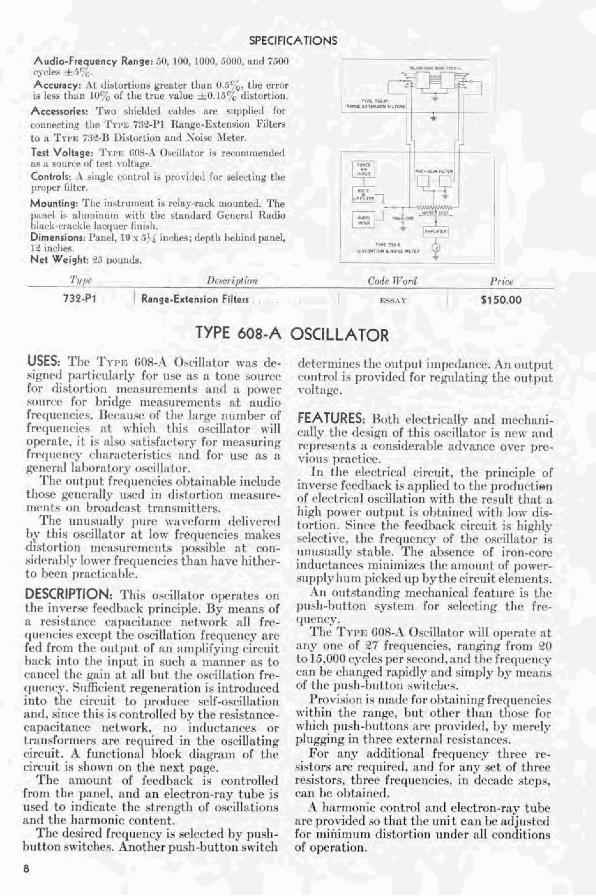
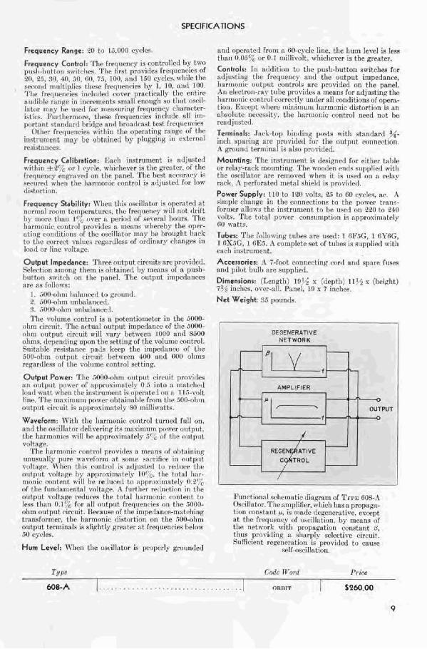
DESCRIPTION: This nsrillntor npcratcs o n tlie invcrsr frrclhnck principle. By nicans nf a resistarlcr c:ip:ici tnncc network i111 fry- quencies escrpt thr oscillation ~ ~ P ~ H C I I V V are f ~ d front thr o~ttput nf a n :~niplifying r i r c~~ i t h d i into tile input in sur.11 :I, nlnnncr as to c:~i~rr l the gain a t 311 4 ~ 1 t t l ~ e n<cillation frr- quency. liilficic~lt regenerat inn i..; it~tmducerl illto the cirruit to prorlt~ve srlf-oscillation and, since t h i s is cnntrollc<l hy tile r~s is tnnce- rapacitancr network, 110 incl~lctnnc,~~ or tr;~nsfnrniers arr requircd in the nscillating uircuit. r-2 funrtian:tl l,lor-k (lingrani of tlw circuit is shon,n on thc rwxt pngc.
The amount of feedhark is controlled from the pancl, and :In electron-my tulw is met1 to intIicnte ~ I I P stmngtl~ of oqcillat ions and the Irnrmonic rontent.
The desired frequency is s r l c r t ~ d by push- button swit clleo. Another push-1)litton switch
drter~nirlcs t l ~ r oi~tpr~t iu~~r.d:tnce. An nu t p ~ ~ t rn i~ t rd is prorirIct1 for rrptlnting fhc n~rtput volt a g ~ .
FEATURES: nr,tl~ rlrctrir;~lly :~nrl mcvhani- r:~lly t i l t * cle3igii of this nscil1:itor is ncn- and rvprcscnts :L consirleral~le nrlrancc over pre- vious pmrt ire.
In t 1 1 ~ elrctrical circuit. tlte principle of in~rrsr feeribark is applicrl to thr prodrrutien of rlrctricnl nscilht i i~n wit11 the r ~ s ~ ~ l t t t ~ i ~ t :L high pnwrr. nutpltt is ohtnined with Inn. riis- tnrtian. Pinrr thr ft*rdE)nr.Tc circuit is highly sclcctive, tlrp f r r q t l ~ n ~ of the oscillntor is r~nrrs~~:tlty st;~F,lr. The al>scncc of iron-tnr~ indu~t~sncps ~ ~ i n i n ~ i x t s t l ~ e amount of pot\-rr- supply Itr~nl pirkrtl 11p l)gtl~cr cirbuit elenlcnts.
. i n o i ~ t ~ t a nrlitig rnerhnniral fcxt~rrc is thc push-l~r~tton system for selcrtinF: t h e frr- rl11ent-y.
Tllr Triw fi08-.4 Osrill:~tor mill op~rntr n t any onr of 27 fr~qilencies, mnging frnm 20 to 1:j.OOO r y r l es per srvonr!, ctrtrl the frequcnry can he rlranpd rapidly ant1 sim~)lp It>* mcxns of tIlr ptrsh-h~~t tnn snitchrs.
Provision is ~nnrlr Fnr nlttainir~g frcqncnries n*itliin the range, Pmt otllcr fh : i r l t l l o s ~ for rnhi~ll prislr-1~1tton.c: are providetl, by rr~crt>ly plurginF: in 1 hrcc ~ x t r r n i ~ l rcsi..;tnnrrs.
la'or any nrlditionai frequency t l w e re- sistors are req~~irctl, and for any set of thrrr wsistitors, thrcr frrqitcnrirs, in dcc:tde steps, can he obtnined. -4 Rnrnlonic cnl~tml and electron-my tlihc
;Ire provirled sn t l ~ a t the unit can he :tdjlutcd for mii~ir~imn distortion under a11 conditions of oper a t' lon.
Frequency Control: The Ir~c,~renry is mntrollcrl hy two pusl~-lr!~t tnr~ sw~tt~hes. ' r h ~ f i r s t prnviuleq Ir~rlilencies of 9(*, 25, !Vln 40. .ill, d i f h , T i , IO l I , anal 150 cy[*lce. tvhilr tilt .wc.r>rrtl n~!sTtiplirs tlicxr ~~PT~UPIIC~PS II,~ 1 . 10, and H)O. 'I'lrc Fr~rl l lrr lcie~ int.lurleal rncpr I~r~~r. t i rn l ly tllc pnt ire :~l~clilhe ~:+IIRP in ir lr-ren~~ntc rrllnll ennugl~ so i l ~ n t orc>il- I~rtr>r may hr ~ ~ s r r l Ir~r t~lr-naurinp I ~ r l u r n r y r.l~i~r:tc.trr- ictir 9. 14'lrrtl>ernlr>re, these frt.rl~~cri<.tes ~nrlrtt?e nil irr l - pc$rt nnt stnnt2nnl I ~ r i ~ l a r :IIIII hrtmrluq~ct test Ireq~~ctwiel'
(Itlrer frrt1lrenries itliiri t l l r u ~ ~ r n t i n g rnrbrc of f hp i n ~ t r ~ l n ~ e n t 11111y l x c,f,t~in~c( Ily p l r ~ ~ ~ i r r g in extrrnlil wsist:rntrs.
Frequency Calibration: F ~ c l i i r l~trumcnt i s nrlju+terl R-itl~in <br 1 ~.ycle, r \ r l l i r l~rrrr i s the gmllrr . ni tilt: Ircrlurnry rnq i lvwl nn thc I~nn~l . 'I'lrt: lwrt :bru7nrarn?* i* swureri when the Iiltrrnnr~ir cl>nt r r~ ! is n~l]u.tcll firr Ianv rliqtort ion.
Frequency Stability: \Tl im t l b i ~ nccillntor is opcnlttd ~ t t
r ~ r ~ r ~ r ~ a l r r m r l tc.rllt,t-rutllreq, tlie Frequmq. n ill nrlt drift l ) ~ . rnnrr tlinn 1 ' , nvrr ~k prriori ch' f irmcll EI~III~S. 'rllt I i i l rn~~rn i r rrrntrrll pnrvirlrq a rnp:trls wl~rrr-lry t l ~ e ol)pr- at in^ tr~nrl i t inr~s OF the rzsr~illntr)r anhy h e l r r i ) t~p l~ t Ir:irli to t l ~ c n ~ t r r r t VAIIIP~ r~ji1irr~1css nf orflinary r-linnges in Inn11 or line vn l t n~ r .
Output Impedance: Three r~utpr i t r i r r r l i t ~ are provitlwl. Srlr.~.tit,n rlrrlrlrlfi thpm i s ol,tz~invtl 11s nirnns LIT x p11s11- Irlitt~,n sn i t c l~ am t l ~ e panel. 1 ' 1 1 ~ output irirperloncw :I rc a tnl!ows:
1. nnn-r~llra Ilalrtncrrl l o ~erluntl. Y. :(If>-ohin un1,nlnncwl. :I. 5000-1dirn ~zr l l~~~ lnnrer~ .
l'llr voll~nle mntrol is r potentiometer in the 5000- trhm r i r r i l i t . 'l'lle n ~ t tlnl 011t put irnp~il l tr~i*e of the 5 R 0 6 n l w rr~~tyrut rim-uit n ill cnry Iwt r re~n l(J00 : ~ r i r l H 3 ) O olin~s, t l r l len i l i~~g Ill,nr! t l r r sv l t i r r~ rrl ltrc rfnlurne m~nf rnl. 511itshlr rr.;i*htrlcr pnAs krrp the irl~perlnnw of the .ilrll-rrll~t~ rn~t 11rlt c*irr-r~it 1)et ivwn 41)O :lnd 1100 o l ln~s rpgnrt11c.c~ of the vnlnir~r rnritrtll srttrrq.
Output Power: The :i000+11m output rirr-uit provirics rill rrilt put pttnpr r d apprn~inmlely O..i i n t~ r n r l~n trltc~l bmtl wnf t rvflelr the inhtrilrnent i~ opera t~ I rrn n 1 l.i-\'ailt linc. ' r lw n l i i \ i r r ~ ~ ~ i i i pr)t*+cr o ~ ) t i ~ i r i ~ ~ h I t ~ front t lw .TOi~-nli~ii outpr~t circuit i~ nrry,muirnntely NX ~ n i l ' l i ~ ~ a t ts .
Waveform: I f ' i th the hnrmonir mntrol t11rn71tt1 F l l l l cm. at111 t h r n s ~ ~ i l l ~ t o t I~P!~\++T~I~R it< tnnxin~l~tn 1llrrvt.r o i i t p ~ ~ t , t lie I~orrlrnnirr wiTI I I P nr lprc~sin~nt~ly .it 111 ~ l r e l r tzt~~t l t vltltngp.
'I'lbe IlnrrarmFr vnr! trol prr~virles u inwtnr of ci1it:ainine: r1nt14unrl.v purr n n ~ r f n r ~ t ~ n t ~I I IP -: i~rif irr in n~ l t pn t I(IIIHK~-. n hc~r t t ~ i r ~.r,nLr!ll ir n~ l j~~c l r -a l 111 rcu111l.c- [ I I ~ nrl!llut vnll:!pe I1.v npprnuirnnlr1.v ,,. thc total llitr- n w ~ ~ i t * r - n t~ t r r~ i w i l l 1lc re I l ~ re< l to n1q1ru~i111j1trI.v (1.9' I r F the f~~n~l r in~er r tn l vo l tng~. h f i i r t l ~ ~ r r~ll~i(mtir+l~ in tllr: trlltput rndtn~e r w I ~ ~ ( . ~ l i llle fntnl lrarnloni<* curnt~nt tat I P ~ Y t l l t ~n 0.1' lur all orltl)rrt Fseqtlrr~c.irr r,rl tllc Simlh- nlirn rr i i tp l~t ciw.~lit. IIPCNIIL~ of t l i r ir~~prlnnr~-n~:~t~l~i~~g trnn.sf~~rmcr, t l l r hnrrnajrbic tlirtairtirr~~ nrl the .;Ulcnlln~ nu! 11111 tvr~uin:tlc i.: slight ly r.iwtter a t Ireque~~rie? I ~ ~ l o w 3 1 <*yr*lt~s,
Hum Level: \!11m the owitlotor is propr ly groirndejl
nnd npernterl From n BO-cycle linp, the l i~ r rn IevrI iii lew tllnn (!.tl:', nr 0 I rn i l l l ~~ r~ l t . rr-ltirhever is the greater.
Controls: I n ntlrlition to the p11s11-hiltton sn~itrhe~ For ~ l ~ j t l ~ t i l l f i the frcquenl-y anrl the o ~ ~ t p t l t impprianw. Ilnrrnrmic. OII tprlt mtntmls $Ire prncirIerl on tile p~bntl. .hi rlrr.tron-rriy tzllw prnrideq s n1enn.s lrrr n t l j us t i n~ the I~armnnir mnt rul ra~rrcr.tly r ~ l ~ ~ l r r nI1 (wn r i i t i ~ l n~ of O ~ C ~ L -
tion. I.;\rrpt rrrherc ln i l~ i r l lun~ Ell~r~nonic. dirtnrtion i q nn nIjrr,l~~tc. nct.e<cit): tlrr hxrnlrlliic c t~ i~ t ru l riccrl nt,l he re~rIj~tsterL.
Terminall: .Lr.li-iop l) ir~rl ing 111)sts with stnnrlnrtl x- i n r e l ~ .upnr.ii~g nrr pnwir lrrl for the output cwnnrr.tion. .\ gm~inul Z~rlzlinal i~ nlru prrrvi~lcrl.
Mounting: The instrunletit is tlrsi~ned for either tatrle or re1:l.v-nick rnountin~. The n-norb~l e i~r i r sltpljlietl with the ncril':rlor nre winoveal ~ h v n it is u s ~ r l o t l u P P I I I ~ mck. :\ ~rcrlncr trr l r i~ r t :~ t shiefrl is prt?viri~ri.
Power Supply: 11 0 I n 120 ~nl t * , a5 to fi0 rytles. nc. il
cirnplr ~II:IIIRC in the muner.t ion~ to the prrwer tranu- ttrrr~lrr nllorr.; ~IIP ill?tr!lllient t r ) Ire 1t4rd c)t l J9lJ to U4O I nlt*. The tnEnl I)orvt.r L Y ~ R T I I I ~ I ~ ~ ~ ~ I I B i~ apprrnimatcly (10 1nrtts.
Tubes: Thr fnlla~n i n ~ t11l)m z~re rlaml: 1 fil%G, I liTtiG. 1 tiS.iG. 1 01.:5. .\ rr l rnpl~te ~ r t of t v h e ~ i? a r ~ p p l i ~ l with m~r.Fi i r l r t r t ~ ~ n ~ n t .
Dlmensionr: ( T e n ~ t l ~ ) I!)' x (tEppt !I) 11 ' 5 u (l~riglit) 7 ' , i~lvhrw. nvrar-all. P:~nel, I9 K 7 ir lcl l~=.
Ne t Weight: 55 prlundq.
I DEGENERATIVE
NETWORK
/

OTHER 6 - R INSTRUMENTS FOR BROADCASTING STATIONS
Frequency Monitors
Power Level Indicators
Volume Controls
Attenuators
Wave Analyzers
Antenna Measuring Equipment
Oscillators, Bridges and Meters for General Testing
GENERAL RADlO COMPANY Cambridge, Mass. - N e w York - Los Angeles - U. S. A.
Farm 511-A- 13904