7/2014 Prodigy M3 Unit Controllers
14
7/2014 507398-01 ©2014 Lennox Industries Inc. Dallas, Texas, USA COMMERCIAL CONTROLS FAQS Litho U.S.A. 507398-01 7/2014 Prodigy ® M3 Unit Controllers PRODIGY 2.0 (M3 UNIT CONTROLLER) FREQUENTLY ASKED QUESTIONS TABLE OF CONTENTS Q1: Is there training and tutorials available for the Prodigy ® unit controller? Page 2 ........................... Q2: How do I program the replacement M3 controller? Page 2 ............................................. Q3: How do I operate the unit in test mode? Page 4 ...................................................... Q4: How can I setup the unit to operate temporarily using the factory-installed return air sensor, prior to installation of the A2 zone sensor? (How do I set the unit up for temporary heating and cooling?) Page 4 Q5: How do I set-up the Economizer operation? Page 5 ................................................... Q6: How do I adjust the Economizer for minimum damper settings? Page 13 ..................................
Transcript of 7/2014 Prodigy M3 Unit Controllers

7/2014 507398-01
©2014 Lennox Industries Inc.Dallas, Texas, USA
COMMERCIAL CONTROLS FAQS Litho U.S.A.
507398-01 7/2014 Prodigy® M3 Unit Controllers
PRODIGY 2.0 (M3 UNIT CONTROLLER) FREQUENTLY ASKED QUESTIONS
TABLE OF CONTENTS
Q1: Is there training and tutorials available for the Prodigy® unit controller? Page 2. . . . . . . . . . . . . . . . . . . . . . . . . . .
Q2: How do I program the replacement M3 controller? Page 2. . . . . . . . . . . . . . . . . . . . . . . . . . . . . . . . . . . . . . . . . . . . .
Q3: How do I operate the unit in test mode? Page 4. . . . . . . . . . . . . . . . . . . . . . . . . . . . . . . . . . . . . . . . . . . . . . . . . . . . . .
Q4: How can I setup the unit to operate temporarily using the factoryinstalled return air sensor, prior to installation of the A2 zone sensor? (How do I set the unit up for temporary heating and cooling?) Page 4
Q5: How do I setup the Economizer operation? Page 5. . . . . . . . . . . . . . . . . . . . . . . . . . . . . . . . . . . . . . . . . . . . . . . . . . .
Q6: How do I adjust the Economizer for minimum damper settings? Page 13. . . . . . . . . . . . . . . . . . . . . . . . . . . . . . . . . .

Page 2
Q1. Is there training and tutorials available for the Prodigy® unit controller?
Yes, we have training and tutorials available on the Lennox Commercial website. You can also go to the following links to
access Prodigy® training sessions and videos:
� Prodigy® Controller Training: http://www.lennoxcommercial.com/support/training.asp
� Controls Link: http://www.lennoxcommercial.com/prodigy
� Prodigy® HowTo Videos: http://www.lennoxcommercial.com/landing/prodigy/how-to-videos.asp
Q2. How do I program the replacement M3 controller?
Reprogram the replacement M3 Unit Controller as follows (follow the flowchart in figure1 for assistance):
Figure 1. Control Replacement

Page 3
Saving USB Profile (Old M3 Unit Controller)If there is a current saved USB Profile, then proceed to Loading USB Profile section. If not available, use the followingprocedure to save a USB Profile.
If the old unit controller is operational, run the SETUP > INSTALL wizard to capture the current configuration of the old unitcontroller. Data such as model number, configuration ID 1 and 2, catalog number, serial number and RTU descriptionshould all be written down in order to configure the new unit controller correctly. Once the above configuration settings hasbeen collected, use the following procedure to save a USB Profile.
1..Insert a compatible USB storage device.
2..Go to SERVICE > REPORT and select USB PROFILE SAVE.
3..The USB PROFILE SAVE screen will appear requesting that you provide a unique name for the profile. Select a uniquename and press SAVE.
NOTE - If “NOT APPLICABLE EQUIPMENT IS NOT PRESENT” is displayed, it may indicate the unit controller was unable
to read the USB storage device. Remove and reinsert USB storage device and attempt to save the USB Profile again. If
problem persist, try a different USB storage device.
4..If successful the screen will return to the REPORT menu options.
Loading USB Profile (New M3 Unit Controller)
The USB profile saves specific data only. Data saved includes configuration information such as Test & Balance settingsand any parameters that were manually configured through SETTINGS > RTU OPTIONS > EDIT PARAMETER screen.
If a current USB Profile is available, use the following procedure to load the existing profile to the new unit controller.
NOTE - If no USB Profile is available, information concerning the unit configuration and accessories installed is available
from the following sources:
� Unit Nameplate (catalog, model and serial numbers)
� Original Factory Unit Configuration label located in control box area
� Unit parameter labels located on unit or in the unit installation instruction should have recorded data concerning any
parameters that were manually changed from defaults.
1..Run SETUP > INSTALL wizard.
2..Select desired LANGUAGE and press SAVE button.
3..Select DATE/TIME and press SAVE button.
4..Select either FAHRENHEIT or CELISUS and press SAVE button.
5..Enter the MODEL NUMBER from the unit nameplate or data collected from the Saving USB profile procedure. PressSAVE to continue.
NOTE - Until Configuration ID 1, positions 1, 2 and 3 are configured correctly, alarm messages will be displayed. Press the
BACK button to clear the messages from the display.
6..Enter the configuration ID 1 and 2 information that was collected prior to removal of the old unit controller. If no informationwas collected, use the information located on a label to the right of the new unit controller in the control box area. Pressthe SAVE button to continue after both IDs have been configured.
NOTE - If the Original Factory Unit Configuration labels are missing from the unit, refer to the M3 Installation and Setup
Guide included with this kit for model number and configuration ID 1 and 2 setting information.
NOTE - Information for steps 7 and 8 is also listed on the Unit Nameplate.
7..Enter the Catalog Number and press SAVE.
8..Enter the Serial Number and press SAVE.
9..Enter the RTU Description and press SAVE.
NOTE - Depending on accessories configured, additional settings will be prompted to be completed.
10..Go to SETUP > NETWORK INTEGRATION and complete the network wizard.
11.. Insert the USB storage device that contains the current saved USB profile.
12..Go to SERVICE > REPORT > USB PROFILE LOAD. Press SAVE to continue.
NOTE - If “NOT APPLICABLE EQUIPMENT IS NOT PRESENT” is displayed, it may indicate either the unit controller was
unable to read the USB storage device or it is missing. Remove and reinsert USB storage device and attempt to load the
USB Profile again. If the issue continues, all data will have to be entered manually.
13..Select the desired USB Profile by using the adjust and set values arrows. Select the desired USB Profile and pressSAVE.
14..The screen will return to the REPORT menu options. Proceed to the next section below.
Page 4
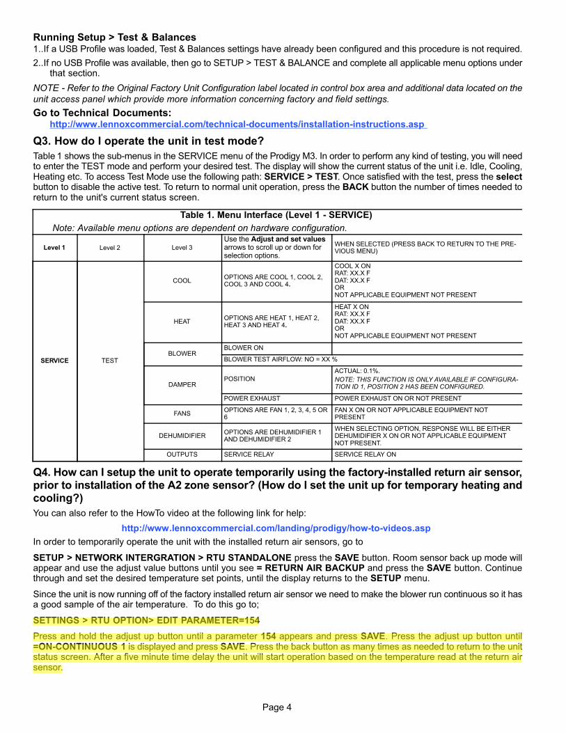
Running Setup > Test & Balances1..If a USB Profile was loaded, Test & Balances settings have already been configured and this procedure is not required.
2..If no USB Profile was available, then go to SETUP > TEST & BALANCE and complete all applicable menu options underthat section.
NOTE - Refer to the Original Factory Unit Configuration label located in control box area and additional data located on the
unit access panel which provide more information concerning factory and field settings.
Go to Technical Documents:http://www.lennoxcommercial.com/technical-documents/installation-instructions.asp
Q3. How do I operate the unit in test mode?
Table 1 shows the sub-menus in the SERVICE menu of the Prodigy M3. In order to perform any kind of testing, you will needto enter the TEST mode and perform your desired test. The display will show the current status of the unit i.e. Idle, Cooling,Heating etc. To access Test Mode use the following path: SERVICE > TEST. Once satisfied with the test, press the selectbutton to disable the active test. To return to normal unit operation, press the BACK button the number of times needed toreturn to the unit's current status screen.
Table 1. Menu Interface (Level 1 - SERVICE)
Note: Available menu options are dependent on hardware configuration.
Level 1 Level 2 Level 3
Use the Adjust and set valuesarrows to scroll up or down forselection options.
WHEN SELECTED (PRESS BACK TO RETURN TO THE PREVIOUS MENU)
SERVICE TEST
COOLOPTIONS ARE COOL 1, COOL 2,COOL 3 AND COOL 4.
COOL X ONRAT: XX.X FDAT: XX.X FORNOT APPLICABLE EQUIPMENT NOT PRESENT
HEATOPTIONS ARE HEAT 1, HEAT 2,HEAT 3 AND HEAT 4.
HEAT X ONRAT: XX.X FDAT: XX.X FORNOT APPLICABLE EQUIPMENT NOT PRESENT
BLOWERBLOWER ON
BLOWER TEST AIRFLOW: NO = XX %
DAMPERPOSITION
ACTUAL: 0.1%.
NOTE: THIS FUNCTION IS ONLY AVAILABLE IF CONFIGURATION ID 1, POSITION 2 HAS BEEN CONFIGURED.
POWER EXHAUST POWER EXHAUST ON OR NOT PRESENT
FANSOPTIONS ARE FAN 1, 2, 3, 4, 5 OR6
FAN X ON OR NOT APPLICABLE EQUIPMENT NOTPRESENT
DEHUMIDIFIEROPTIONS ARE DEHUMIDIFIER 1AND DEHUMIDIFIER 2
WHEN SELECTING OPTION, RESPONSE WILL BE EITHERDEHUMIDIFIER X ON OR NOT APPLICABLE EQUIPMENTNOT PRESENT.
OUTPUTS SERVICE RELAY SERVICE RELAY ON
Q4. How can I setup the unit to operate temporarily using the factory-installed return air sensor,prior to installation of the A2 zone sensor? (How do I set the unit up for temporary heating andcooling?)
You can also refer to the HowTo video at the following link for help:
http://www.lennoxcommercial.com/landing/prodigy/howtovideos.asp
In order to temporarily operate the unit with the installed return air sensors, go to
SETUP > NETWORK INTERGRATION > RTU STANDALONE press the SAVE button. Room sensor back up mode willappear and use the adjust value buttons until you see = RETURN AIR BACKUP and press the SAVE button. Continuethrough and set the desired temperature set points, until the display returns to the SETUP menu.
Since the unit is now running off of the factory installed return air sensor we need to make the blower run continuous so it hasa good sample of the air temperature. To do this go to;
SETTINGS > RTU OPTION> EDIT PARAMETER=154
Press and hold the adjust up button until a parameter 154 appears and press SAVE. Press the adjust up button until=ONCONTINUOUS 1 is displayed and press SAVE. Press the back button as many times as needed to return to the unitstatus screen. After a five minute time delay the unit will start operation based on the temperature read at the return airsensor.
LWM02
Highlight

Page 5
CAUTION: The use of this unit as a construction heater or air conditioner is not recommended during anyphase of construction. Very low return air temperatures, harmful vapors and operation of the unit with clogged ormisplaced filters will damage the unit. If this unit has been used for heating or cooling of buildings or structuresunder construction, the following conditions must be met or the warranty will be void:
� The vent hood must be installed per these installation instructions.
� A room thermostat must control the unit. The use of fixed jumpers that will provide continuous heating orcooling is not allowed.
� A pre-filter must be installed at the entry to the return air duct.
� The return air duct must be provided and sealed to the unit.
� Return air temperature range between 55°F (13°C) and 80°F (27°C) must be maintained.
� Air filters must be replaced and pre-filter must be removed upon construction completion.
� The input rate and temperature rise must be set per the unit rating plate.
� The heat exchanger, components, duct system, air filters and evaporator coil must be thoroughly cleanedfollowing final construction clean-up.
� The unit operating conditions (including airflow, cooling operation, ignition, input rate, temperature rise andventing) must be verified according to these installation instructions.
Q5. How do I set-up the economizer operation?
1.1. General
The economizer, when configured, controls:
� Damper position, which determines how much outdoor air is used to meet free cooling or indoor air quality requirements,
and
� Optional power exhaust fans.
On a cooling demand, outdoor air is used for free cooling instead of first-stage compressor(s) when outdoor air is suitable.
1.2. Enabling Economizer and Settings
To enable the economizer if installed go to SETUP > INSTALL and go through the wizard. When reaching Configuration ID1, position 2 will need to be set to the applicable type of economizer. Valid types are as indicated below:
� M = Motorized Outdoor Air Damper Only
� T = Economizer - Temperature (Note: Used for both setpoint and offset temperature control.)
� G = Economizer - Global
� S = Economizer - Single Enthalpy
� D = Economizer - Dual Enthalpy
The following options are available depending on economizer set above. These settings are available through the mainmenu at SETUP > TEST & BALANCE > DAMPER.
Table 2 . Menu Interface (Level 1 - SETTINGS)
Note: Available menu options are dependent on hardware configuration.
Level 2 Level 3 Level 4 Level 5USE THE ADJUST AND SET VALUES ARROWS TOSCROLL UP OR DOWN FOR SELECTION OPTIONS.
RTU OPTION DAMPER
ECONOMIZER ENTHALPY OFFSET = X MA
ECONOMIZER TEMP ECON TYPE = TEMPERATURE OFFSET OR TEMPERATURE SETPT
ECONOMIZER OAT SETPOINT = XX.X F
FREE COOLING SUPPLY AIR SETPOINT = XX F
MIN DAMPER POSITION BLOWER ON HIGH = X.X %
MIN DAMPER POSITION BLOWER ON LOW = X.X %
DEMAND CONTROL VENT DAMPER START OPEN = XXXX.X PPM
DEMAND CONTROL VENT DAMPER FULL OPEN = XXXX.X PPM
DEMAND CONTROL VENT DAMPER MAX OPENING = XXX.X%
POWER EXHAUST ON BY ECON TRAVEL = XX.X %
FRESH AIR HEATING ENABLEFAH = YES OR NO
FRESH AIR HEATING FAH SETPOINT = XX F
FRESH AIR COOLING ENABLEAFC = YES OR NO
FRESH AIR COOLING AFC SETPOINT = XX F

Page 6
1.3. Damper Operation During Free Cooling
These are operating profile options for the economizer damper (Parameter 164 - ECONOMIZER PROFILE) during freecooling when any compressor is on and can be selected as follows:
Option 0: Damper continues to modulate while compressors are on, but the effect of mechanical cooling may force thedamper closed to its minimum position. After compressor starts, the free cooling setpoint is lowered to 45°F.
Option 1: Damper opens to its maxopen position (Parameter 132 - MIN DAMPER POSITION) when any compressorsstart.
NOTE - When using Option 1 and after the compressor is stopped, the M3 shall resume damper modulation.
Option 2: Damper continues to modulate while compressors are on, but the effect of mechanical cooling may force thedamper closed to its minimum position. This is the factory default setting.
� Holdsoff compressor on Y2 call until damper has modulated to maximum position (Parameter 132 - MIN DAMPER
POSITION) for three minutes.
� After three minutes, Y2 allows compressor to start. After compressor starts, the free cooling setpoint is lowered to 45°F.
Damper is not locked at maximum open while compressor is on, but modulates to maintain 45°F discharge air temperat
ure.
� When Y2 is satisfied, compressor goes off and free cooling setpoint is restored to 55°F.
Option 3: Same as Option 2, but with a 10 minute delay instead of a three minute delay.
1.4. Free Cooling Compressor Lockout Mode
Go to SETTINGS > RTU OPTION > EDIT PARAMETER = 285 (FRCL COMP LCKOUT MD). Default value is 0. Range is 0to 3.
0 = Disable Free Cooling Low Ambient Compressor Lockout (default).
1 = Lockout Compressor whenever the outdoor air is suitable regardless of outdoor air temperature.
2 = Enable Free Cooling Low Ambient Compressor Lockout.
1.5. Free Cooling Low Ambient Lockout Set Point
When the outdoor air temperature falls below the freecooling set point, and outdoor air is suitable, then mechanical coolingis kept off, or is turned off if it is on.
Go to SETTINGS > RTU OPTION > EDIT PARAMETER = 108 (FREE LO AMB LCKT SP). Default value is 55°F. Range is44 to 80°F.
1.6. Outdoor Air Suitable for Free Cooling
The M3 Unit Controller displays the outdoor air suitability information on the status screen. There are six options available todetermine outdoor air suitability for free cooling and are described in table 3.
The appropriate sensors are provided when the economizer is factory-configured. When the economizer is field-installedand configured, the outdoor enthalpy mode requires additional field-provided sensor(s). See table 3. The TEMP mode uses
sensors provided with all units.

Page 7
Table 3. Free Cooling Options
Parameter Screen NameShort
DescriptionRangeSetting
DefaultSetting
Config ID1POS 2)
Outdoor air is suitable for freecooling when:
160 ECON FREECL TEMP SP
Economizer FreeCooling
TemperatureSetpoint
40 F - 75 F 75°F TOutdoor air temperature (RT17) is lessthan the Outdoor Air Temperature setpoint value.
161 ECON FRCL TMP OFFST
Economizer FreeCooling
TemperatureOffset
0°F - 40°F 10°F TOutdoor air temperature (RT17) is lessthan return air temperature (RT16) byat least the parameter value.
162 ECN FREECL ENTH SPEconomizer FreeCooling Enthalpy
Setpoint10mA - 19 mA 12.0 mA S
Outdoor air enthalpy (A7) is less thanenthalpy set point parameter.
163 ECN FRCL ENTH OFFSTEconomizer FreeCooling Enthalpy
Offset1 mA - 5 mA 1.0 mA D
Outdoor air enthalpy* (A7) is less thanreturn air enthalpy (A62) by at least theOFFSET value.
Global Not Applicable Not Applicable Not ApplicableNot
ApplicableG
Global input is energized by (P297-9).This setting is also used for outdoor airdamper applications. Global input alsobrings on the blower. (This mode isNOT used when OAS signal is provided via network connection. GLO isonly used when a 24VAC signal is usedto energize the P297-9 GLO input.)
Temp Not Applicable Not Applicable Not ApplicableNot
Applicable
Either of the TEMP modes (set point oroffset) can be used when a networkOAS signal is provided by an energymanagement or building control system, via BACnet, LonTalk, or L Connection. The network can commandOAS, NOT OAS, or AUTO. AUTO returns to local control of OAS, which isthe selected TEMP mode..
Note: Enthalpy includes effects of both temperature and humidity.
1.7. Enthalpy Set Point
This setting pertains to the outdoor enthalpy free cooling mode only. The M3 Unit Controller will enable free cooling whenoutdoor air enthalpy (A7) is less than the enthalpy set point. Figure 2 shows the approximate enthalpy sensor output atvarious temperatures and percentage of relative humidity.
40°F 50°F 60°F 70°F 80°F 90°F 100°F
30
20
10
40
50
60
70
80
90
100
Figure 2. Enthalpy Sensor Output Current Honeywell C7400
1.8. Free Cooling Damper Maximum Position
Damper Maximum position is set using the following menu path.
SETUP > TEST & BALANCE > DAMPER > DAMPER MAX OPENING = .%
1.9. Minimum Damper Position
Use the following menu path to modified the minimum damper positions for both high and low operations.
SETUP > TEST & BALANCE > DAMPER > MIN DAMPER POSITION BLOWER ON HIGH = .%

Page 8
SETUP > TEST & BALANCE > DAMPER > MIN DAMPER POSITION BLOWER ON LOW = .%
1.10. Motorized Outdoor Air Damper
Set damper position according to “Minimum Damper Position” section 1.9. For normal operation, make sure the motorizedoutdoor air damper is set correctly in CONFIGURATION ID 1, character position two. Character to be used is M. Thedamper will open to the specified position during the occupied time period and close during the unoccupied time period.
1.11. Economizer Checkout
The following checkout procedures are completed with unit energized. Confirm proper operation of the heartbeat LED. Step1 will determine whether the economizer is allowing full damper travel. Use step 2 when the damper does not respond to step1.
Steps 3, 4, 5, and 6 checkout the operating modes; checkout only the mode that applies to the unit being worked on.
CAUTION - Power exhaust fans will be functional. To prevent operation of power exhaust fans, disconnect power to unit andthen PED jack/plug P/J18.
Step 1.ECONOMIZER OUTPUT VOLTAGE
A Go to SERVICE > TEST > DAMPER>POSITION > DAMPER POSITION ACTUAL: 0.0% The motor will slowlymodulate to the closed position.
B Change DAMPER POSITION ACTUAL to 100.0%.The motor will slowly modulate to the fully opened position.
C If the motor does not respond, go to step 2. If the motor does respond properly, go to the appropriate mode of operation checkout.
Step 2.OUTDOOR ENTHALPY OPERATION
A Go to SERVICE > TEST > DAMPER > POSITION > DAMPER POSITION ACTUAL: 0.0%
B Adjust the DAMPER POSITION ACTUAL: to 0.0% position.
C Measure the voltage on P262 between pin 3 (VOT damper control) and pin 2 (GND) using pin 1 as common.Voltage should read approximately 2 VDC.
D Adjust the DAMPER POSITION ACTUAL: to 100.0% position.
NOTE - Allow approximately 90 seconds for actuator to react.
E Measure the voltage between P262 between pin 3 (VOT damper control) and pin 2 (GND) using pin 1 as common. Voltage should read approximately 10 volts DC. If not, check wiring and trouble shoot system.
Step 3.OUTPUT VOLTAGE CHECK
In the ODE mode, dampers open for free cooling when the outdoor enthalpy is less than the enthalpy set point; dampers will
try to modulate discharge air temperature (RT6) to 55°F (13°C).
A Go to SETUP > INSTALL > press SAVE until you get to the Configuration ID 1, position 2 change to S for Economizer Single Enthalpy and press SAVE.
B To simulate low outdoor enthalpy. Disconnect A7 outdoor enthalpy sensor jack/plugs J/P104. Connect a 200 ohmresistor across plug J104-1 and J104-2. J104 is located in the filter access area.
C Check all connections and wiring between J104 and the control.
Step 4.OUTDOOR ENTHALPY DIFFERENTIAL MODE OF OPERATION
In the DIF mode, dampers open for free cooling when the outdoor air enthalpy is lower than the return air enthalpy; damperswill modulate discharge air temperature (RT6) to 55°F.
A Go to SETUP > INSTALL > press SAVE until you get to the Configuration ID 1 and change the position two to D forEconomizer Dual Enthalpy and press SAVE if performing an economizer field-install.
B Use two resistors to simulate outdoor air enthalpy suitable.
� Disconnect A62 return air enthalpy sensor jack/plug J/P105. Place a 750 ohm resistor between J105-1 and J105-3.J/P105 is located in the filter access area.
� Disconnect A7 outdoor enthalpy sensor jack/plugs J/P104. Connect a 100 ohm resistor across J104-1 and J104-2.
Step 5.ALL TEMPERATURE MODES OF OPERATION
In the Economizer – Temperature mode, the damper opens for free cooling when the outdoor air temperature is:
� Less than return air temperature
� Parameters 160, 161, 162 and 163 less than return air temperature
� Less than Parameters 160, 161, 162 and 163.
In all modes, dampers will try to modulate discharge air temperature (RT6) to 55°F.
Refer to the “Displaying Sensor Inputs" section to read return air (RT16) and outdoor air (RT17) temperatures. If outdoor airis not cooler than return air, simulate a colder outdoor air temperature with a resistor. Select a resistor value that corresponds to a temperature (see table 4):

Page 9
� Less than return air temperature
� Parameters 160, 161, 162 and 163 less than return air temperature
� Less than Parameters 160, 161, 162 and 163
Table 4. TMP Mode Resistor Values
Temp. °F (°C) Size Resistor Temp. °F (°C) Size Resistor Temp. °F (°C) Size Resistor Temp. °F (°C) Size Resistor
30 (-1) 34,566 50 (10) 19,904 70 (21) 11,884 90 (32) 7,332
40 ( 4) 26,106 60 (16) 15,313 80 (27) 9,298 100 (38) 5,826
A Locate RT17 sensor in unit. Disconnect 1/4" quick connect terminals on wires leading from sensor.
B Jumper RT17 wires leading back to control with the appropriate resistor.
C Check all connections and wiring between RT17 and the M3 Unit Controller, and between RT16 and the M3 UnitController.
Table 5. Economizer Parameters
Control Parameter Control Value
Units DescriptionNo Screen Name Parameter Short Description Min. Default Max.
160 ECON FREECL TEMP SPEconomizer Free Cooling
Temperature Setpoint40 75 75 °F
Outdoor Air Temperature is less than parameter setpointbetween 41-70°F, orwhen Outdoor Air temperature is less thanReturn Air Temperature between 0-40°F.
161 ECON FRCL TMP OFFSETEconomizer Free Cooling
Temperature Offset0 10 40 °F
Economizer FreeCooling TemperatureOffset
162 ECON FREECL ENTH SPEconomizer Free Cooling
Enthalpy Setpoint10 12.0 19 mA
Economizer FreeCooling Enthalpy Setpoint
163 ECN FRCL ENTH OFFSTEconomizer Free Cooling
Enthalpy Offset1 1.0 5 mA
Economizer FreeCooling Enthalpy Offset
Step 6.GLOBAL MODULATING MODE OF OPERATION
In the GLO (modulating) mode, dampers modulate open for free cooling when the global input is energized; dampers will tryto modulate discharge air temperature (RT6) to 55°F.
NOTE - The global input turns on the blower.
A Set global mode using the CONFIGUATION ID 1, position 2, character G.
B Connect a jumper between A55_P297-1 (24VAC) and A55_P297-9 (global). The blower will be energized and thedamper will slowly open if discharge air temperature (RT6) is greater than 55°F.
C Disconnect 24VAC to A55_P297-9. The blower will turn off and the damper will close.
D If the damper does not actuate check all connections and wiring between P262A and B.
Step 7.ENTHALPY SENSOR OPERATION (A7 and A62)
A Connect a direct current ammeter as shown in figure 3 to measure current output of A7 or A62.

Page 10
DISCONNECT J/P104
PLACE JUMPER WIRE HERE
READCURRENTHERE
DC AMMETER- +
Damper Travel: % of Maximum Open
DISCONNECT J/P105
PLACE JUMPER WIRE HERE
READCURRENTHERE
DC AMMETER- +
Measure A62 Current in SeriesMeasure A7 Current in Series
Figure 3. Measure A7 and A62 Current in Series
B The reading will be between 4 and 20 ma. depending on outdoor temperature and humidity. Refer to figure 4 toapproximate reading.
40°F 50°F 60°F 70°F 80°F 90°F 100°F
30
20
10
40
50
60
70
80
90
100
Figure 4. Enthalpy Sensor Output Current Honeywell C7400
C If the meter reads zero, check sensor wiring harness for continuity and/or check polarity of sensor wiring.
1.12. Demand Control Ventilation
1.12.1. General
A field-provided and installed indoor air quality (IAQ) sensor can be used with the modulating economizer or OADM to control carbon dioxide levels in the conditioned space. The carbon dioxide level in a space is an indicator of the number ofpeople occupying a room. As the carbon dioxide level rises (indicating the occupancy of a room has increased), dampersmodulate open - regardless of outdoor air suitability. Likewise, as the carbon dioxide level falls (indicating the occupancy has
decreased), dampers modulate further closed.
Standard economizer installations have a minimum fresh air ventilation requirement based on maximum room occupancy.With standard economizer use, the amount of air required for maximum room occupancy is heated or cooled with eachheating or cooling cycle. IAQ installations use the maximum amount of required ventilation air only with maximum room
occupancy; less outdoor air needs to be heated or cooled when fewer people are in the conditioned space.
If the economizer is operating in the free cooling mode and the indoor air quality control requires the damper to open further,the indoor air quality demand will override the free cooling demand.
The IAQ function is not energized during the unoccupied or night time period.
NOTE - The IAQ sensor may also be used with systems containing a motorized outdoor air damper.

Page 11
1.12.2. Default Operation
The M3 Unit Controller has a 0-10VDC indoor air quality input for a standard 0-2000ppm carbon dioxide sensor. The economizer starts opening at a carbon dioxide level of 500 ppm (“start open" set point) and reaches full open at a carbon dioxidelevel of 1000ppm (“full open" set point). The damper opens to 100%. Determine damper travel position using the following
formula.
% Damper Travel = carbon dioxide ppm - Start Open ppm5
Example: At a carbon dioxide level of 750ppm, the damper will be approximately 50% open:
% Damper Travel = 750-500 = 50%5
Use the menu interface to read carbon dioxide ppm. DATA > IN/OUTPUTS > SENSORS > C02. Figure 5 shows default orproportional operation.
33
66
100
500Parameter 118
1000Parameter 119
Low Temp. Operation High Temp. Operation
CO2 (ppm)
10°F Parameter122
20°F
30°F
40°F Parameter123
105°F Parameter 120
95°F
85°F
75°F Parameter 121
0
Min. Position
Dam
per
Tra
vel:
% o
fM
axim
um
Op
en
(Para
mete
r 117
Figure 5. Default Direct Current Operation
1.12.3. Parameter Adjustments
Default indoor air quality economizer operation is based on common or average applications. Adjustments may be made tothe indoor air quality parameters to alter operation or meet required specifications. Use the user interface to change Parameter 117 through 120.
SETTINGS > RTU OPTIONS > EDIT PARAMETER.
Select a demand control ventilation mode or outdoor air control mode with Parameter 134. Modes 4 and 5 will bring on the
unit blower when demand control ventilation calls for maximum damper open, and returns to auto-blower when demandcontrol ventilation damper returns to 0. The other modes only operate when the unit blower is on, but will not bring it onthemselves.
Some applications require a different carbon dioxide set point range than default settings. Damper “start open" (Parameter118 or 124) and “full open" (Parameter 119 or Parameter 125) carbon dioxide set points may be adjusted from 0 to 1992ppm.Use the following formula to determine damper travel.
NOTE - When changing carbon dioxide set point range, “start open" set point should be less than “full‐open" set point.
% Damper Travel = carbon dioxide ppm - Start Open ppm X Max Open (Parameter 117) Full Open - Start Open
Example: An application requires the dampers open at 800 CO2 ppm and reach full open at 1200. If the carbon dioxide level in the space reads 1000 ppm, calculate the damper percent open as follows.
% Damper Travel = 1000 - 800 or 200 or .5 = 0.5 x 100 = 50%1200 - 800 400

Page 12
Table 6. Demand Control Damper Parameters
Control Parameter Control Value
Units DescriptionNo Screen Name
Parameter ShortDescription Min. Default Max.
117 DCV MAX DAMPER OPENDemand Control
Ventilation MaximumDamper Open
0 95 100 %
� Damper “start open" CO2 set point for
Demand Control Ventilation.
� Level where fresh air damper begins to
open.
118 DCV DAMP START OPENDemand Control
Ventilation DamperStart Open
0 705 2000 PPM
� Damper “start open" CO2 set point for
Demand Control Ventilation.
� Level where fresh air damper begins to
open.
119 DCV DAMP FULL OPEN
Demand ControlVentilation MaximumDamper Full Open
Setpoint
0 1200 2000 PPM
� Damper “full open" CO2 set point for
Demand Control Ventilation.
� Level where fresh air damper is opened
to maximum.
120 DCV HI TMP OV FL CL
Demand ControlVentilation Outdoor
Air Control HiTemperature Override
Full Closed
-31 105 132 °F
� High outdoor air temp. where fresh air
damper is closed to minimum position.
� Also used for outdoor air control.
121 DCV HI TMP OV ST CL
Demand ControlVentilation Outdoor
Air Control HiTemperature Override
Start Closing
-31 75 132 °F
� High outdoor air temperature where
fresh air damper begins to close.
� Also used for outdoor air control.
122 DCV LO TMP OV FL CL
Demand ControlVentilation Outdoor
Air Control LowTemperature Override
Full Closed
-31 10 132 °F
Low outdoor air temperature where freshair damper is closed to minimum positionfor Demand Control Ventilation and Outdoor Air Control.
123 DCV LO TMP OV ST CL
Demand ControlVentilation Outdoor
Air Control LowTemperature Override
Start Closing
-31 40 132 °F
� Low outdoor air temp. where fresh air
damper begins to close.
� Also used for outdoor air control.
1.12.3.1. Set Point Control Option
Set point control mode is commonly used in areas with high occupancy and frequent change out such as classrooms orconference rooms.
In applications requiring this on/off damper response to carbon dioxide levels, set the start open (Parameter 118 - DCVDAMP START OPEN) set point higher than the full open (Parameter 119 - DCV DAMP FULL OPEN) set point. The damperswill drive to fully-open position immediately. Figure 6 shows the set point control option.
Change Parameters 122 (DCV LO TMP OV FL CL) and 123 (DCV LO TMP OV ST CL) to set the minimum outdoor temperature limits. Change Parameters 120 (DCV HI TMP OV FL CL) and 121 (DCV HI TMP OV ST CL) to set the maximum
temperature value.
IMPORTANT - Mixed air temperatures less than 45°F (7°C) on units with an aluminized heat exchanger or less than 30°F(-1°C) on stainless steel heat exchangers will void the manufacturer's warranty.

Page 13
Min. Position
100 Parameter 117
Parameter 119
(full)
Parameter 118
(start)
carbon dioxide (ppm)
Max. Open
Close Open
Figure 6. Set point Control Indoor Air Quality Option
1.12.3.2. Determining Indoor Air Quality Inputs
DATA> IN/OUTPUTS > SENSORS menu selection from the M3 Unit Controller menu display.
Q6: How do I adjust the Economizer for minimum damper settings?
Use the following menu path to modified the minimum damper positions for both high and low operations.
SETUP > TEST & BALANCE > DAMPER > MIN DAMPER POSITION BLOWER ON HIGH = .%