7135/633/SP 2011-12-20 2012-02-21 SANS 633: GEOTECHNICAL ... 96-10 _DSS_ 633.pdf · SANS 633:2012...
35
DRAFT SOUTH AFRICAN STANDARD (DSS): PUBLIC ENQUIRY STAGE Document number SANS 633 Reference 7135/633/SP Date of circulation 2011-12-20 Closing date 2012-02-21 Number and title: SANS 633: GEOTECHNICAL INVESTIGATIONS FOR TOWNSHIP DEVELOPMENT Remarks: PLEASE NOTE: • The technical committee, SABS SC 59P: Construction standards – Geotechnical standards responsible for the preparation of this standard has reached consensus that the attached document should become a South African standard. It is now made available by way of public enquiry to all interested and affected parties for public comment, and to the technical committee members for record purposes. Any comments should be sent by the indicated closing date, either by mail, or by fax, or by e-mail to SABS Standards Division Attention: Compliance and Development department Private Bag X191 Pretoria 0001 Fax No.: (012) 344-1568 (for attention: dsscomments) E-mail: [email protected] Any comment on the draft must contain in its heading the number of the clause/subclause to which it refers. A comment shall be well motivated and, where applicable, contain the proposed amended text. • The public enquiry stage will be repeated if the technical committee agrees to significant technical changes to the document as a result of public comment. Less urgent technical comments will be considered at the time of the next amendment. THIS DOCUMENT IS A DRAFT CIRCULATED FOR PUBLIC COMMENT. IT MAY NOT BE REFERRED TO AS A SOUTH AFRICAN STANDARD UNTIL PUBLISHED AS SUCH. IN ADDITION TO THEIR EVALUATION AS BEING ACCEPTABLE FOR INDUSTRIAL, TECHNOLOGICAL, COMMERCIAL AND USER PURPOSES, DRAFT SOUTH AFRICAN STANDARDS MAY ON OCCASION HAVE TO BE CONSIDERED IN THE LIGHT OF THEIR POTENTIAL TO BECOME STANDARDS TO WHICH REFERENCE MAY BE MADE IN LAW. AZ96.10 2008/08/08 sabs pta
Transcript of 7135/633/SP 2011-12-20 2012-02-21 SANS 633: GEOTECHNICAL ... 96-10 _DSS_ 633.pdf · SANS 633:2012...

DRAFT SOUTH AFRICAN STANDARD (DSS):
PUBLIC ENQUIRY STAGE
Document number SANS 633
Reference 7135/633/SP
Date of circulation 2011-12-20
Closing date 2012-02-21
Number and title: SANS 633: GEOTECHNICAL INVESTIGATIONS FOR TOWNSHIP DEVELOPMENT Remarks:
PLEASE NOTE:
• The technical committee, SABS SC 59P: Construction standards – Geotechnical standards responsible for the preparation of this standard has reached consensus that the attached document should become a South African standard. It is now made available by way of public enquiry to all interested and affected parties for public comment, and to the technical committee members for record purposes. Any comments should be sent by the indicated closing date, either by mail, or by fax, or by e-mail to
SABS Standards Division Attention: Compliance and Development department Private Bag X191 Pretoria 0001 Fax No.: (012) 344-1568 (for attention: dsscomments) E-mail: [email protected]
Any comment on the draft must contain in its heading the number of the clause/subclause to which it refers. A comment shall be well motivated and, where applicable, contain the proposed amended text.
• The public enquiry stage will be repeated if the technical committee agrees to significant technical
changes to the document as a result of public comment. Less urgent technical comments will be considered at the time of the next amendment.
THIS DOCUMENT IS A DRAFT CIRCULATED FOR PUBLIC COMMENT. IT MAY NOT BE REFERRED TO AS A
SOUTH AFRICAN STANDARD UNTIL PUBLISHED AS SUCH.
IN ADDITION TO THEIR EVALUATION AS BEING ACCEPTABLE FOR INDUSTRIAL, TECHNOLOGICAL,
COMMERCIAL AND USER PURPOSES, DRAFT SOUTH AFRICAN STANDARDS MAY ON OCCASION HAVE TO BE CONSIDERED IN THE LIGHT OF THEIR POTENTIAL TO BECOME STANDARDS TO WHICH REFERENCE MAY BE MADE IN LAW.
AZ96.10 2008/08/08 sabs pta

ISBN 978-0-626- SANS 633:2012 Edition 1
SOUTH AFRICAN NATIONAL STANDARD
Soil profiling and rotary percussion borehole logging on dolomite land in Southern Africa for engineering purposes
Published by SABS Standards Division 1 Dr Lategan Road Groenkloof ���� Private Bag X191 Pretoria 0001 Tel: +27 12 428 7911 Fax: +27 12 344 1568 www.sabs.co.za SABS

SANS 633:2012 Edition 1
Table of changes
Change No. Date Scope
Acknowledgement The SABS Standards Division wishes to acknowledge the input of the South African Institution of Civil Engineering, South African Institute for Engineering and Environmental Geologists, and the Association of Engineering Geologists, as well as the work done by the National Department of Public Works and the National Dolomite Risk Management Working Committee established on instruction of the Cabinet Committee on Governance and Administration, in developing this document. Foreword This South African standard was approved by National Committee SABS TC 59P, Construction standards – Geotechnical standards, in accordance with procedures of the SABS Standards Division, in compliance with annex 3 of the WTO/TBT agreement. This document was published in xxxx 2012. Reference is made in 4.1.2 to the “relevant national system”. In South Africa this means the South African Coordinate System as set out in the National Control Survey Network maintained by the Chief Directorate: Surveys and Mapping of the Department of Land Affairs. Annex A is for information only. Introduction This document was written for the purposes of soil and rock profiling of areas underlain by dolomite in Southern Africa. It serves to standardize the methods, procedures and nomenclature required to accurately describe the ground profile in dolomite areas for the purposes of investigation for infrastructure development and the repair of subsidence-related events on dolomite land. This information is essential for the assessment of land usage, for planning purposes, and for the initial design of foundations and soil structures of all types.

SANS 633:2012 Edition 1
1
Contents
Page Acknowledgement Foreword Introduction 1 Scope ...................................................................................................................................... 3 2 Normative references.............................................................................................................. 3 3 Definitions ............................................................................................................................... 3 4 Requirements.......................................................................................................................... 7 4.1 General ........................................................................................................................ 7 4.2 Soil profiling ………………………………………………………………………................ 8 4.3 Rotary percussion borehole logging …………………………………………………........ 20 Annex A (informative) The typical Southern African soil profile ................................................ 30 Bibliography .............................................................................................................................. 32

SANS 633:2012 Edition 1
2
This page is intentionally left blank

SANS 633:2012 Edition 1
3
Soil profiling and rotary percussion borehole logging on dolomite land in Southern Africa for engineering purposes 1 Scope This standard establishes requirements for soil profiling and rotary percussion borehole logging on dolomite land. 2 Normative references The following referenced documents are indispensable for the application of this document. For dated references, only the edition cited applies. For undated references, the latest edition of the referenced document (including any amendments) applies. Information on currently valid national and international standards can be obtained from the SABS Standards Division. SANS1936-1:2012, Development of dolomite land – Part 1: General principles and requirements. SANS1936-2, Development of dolomite land – Part 2: Geotechnical investigations and determinations. SANS1936-3, Development of dolomite land – Part 3: Design and construction of buildings, services and infrastructure. SANS1936-4, Development of dolomite land – Part 4: Risk management. SANS 2001-CC2, Construction works – Part CC2: Concrete works (minor works). 3 Definitions For the purposes of this document, the following definitions apply. 3.1 borehole usually vertical penetration into the ground with the recovery of soil or rock (or both) material 3.2 borehole log detailed record of the geological formations penetrated, groundwater conditions encountered, test locations of the borehole, and which a) is based on visual inspection of samples recovered during the drilling process,

SANS 633:2012 Edition 1
4
b) shows the positions of physical measurements made in the borehole together with their results, if appropriate, and
c) indicates the physical location of the borehole by way of its coordinates and elevation 3.3 chip log detailed description of the chips retrieved through rotary percussion drilling 3.4 clast fragment of pre-existing rock in a clastic rock 3.5 cohesive soil predominantly fine grained (clayey or silty) soil 3.6 collapsible soil soil with an open textured structure and a low density that, when subjected to a combination of direct actions and an increase in soil moisture content, experiences sudden or rapid settlement 3.7 discontinuity surface across which some property of the soil or rock is discontinuous, including bedding planes, joints, fissures, fractures and shear planes 3.8 disturbed sample sample obtained from the soil without preservation of the soil structure 3.9 dolomite land land underlain by dolomite or limestone residuum or bedrock (or both), within the Malmani Subgroup and Campbell Rand Subgroup, typically at depths of no more than a) 60 m in areas where no de-watering has taken place and the local authority has jurisdiction, is monitoring and has control over the groundwater levels in the areas under consideration; or b) 100 m in areas where de-watering has taken place or where the local authority has no jurisdiction or control over groundwater levels NOTE For more information on dolomite land in South Africa, see annex B of SANS 1936-1:2012. 3.10 expansive soil fine-grained soil the clay mineralogy of which is such that it changes in volume to varying degrees in response to changes in moisture content, i.e. the soil increases in volume (heaves or swells) upon wetting up and decreases in volume (shrinks) upon drying out 3.11 granular soil non-cohesive soil predominantly sandy and gravelly soil

SANS 633:2012 Edition 1
5
3.12 grout homogeneous mixture of a cementitious binder and water, often combined with sand, bentonite or other additives (or both), and that sets on curing 3.13 gryke grike negative, valley-like feature in the bedrock formed as a result of preferential weathering along vertical or near-vertical joints 3.14 hardness rock property that indicates a) resistance to indentation or scratching; or b) the strength of the rock NOTE Field and laboratory test descriptors for determining rock hardness are given in 4.2.2.5. 3.15 log continuous record of observations made of the materials and fluids recovered from a borehole 3.16 organic matter matter that consists of plant or animal (or both) organic materials, and the conversion product of those materials, e.g. humus 3.17 pebble marker gravelly soil that forms the demarcation between the transported soils which overlie it, and the country rock or residual soils which underlie it NOTE For more information on pebble markers, see annex A. 3.18 pedogenic material soil that has become cemented or has been replaced by iron or manganese oxide, calcium carbonate or silica NOTE Pedogenic material includes materials such as ferricrete, manganocrete, calcrete and silcrete. 3.19 pinnacle positive, tower-like portion of bedrock formed as a result of preferential weathering along vertical or near-vertical joints 3.20 residual soil material formed by the in-situ decomposition (chemical weathering) or the disintegration (physical weathering) of rock, to a degree of softness of the intact soil that gives an unconfined compressive strength of less than 1 MPa 3.21 rock igneous, metamorphic, or sedimentary material, other than pedogenic material, with an unconfined compressive strength in excess of 1 MPa of the intact or unjointed material

SANS 633:2012 Edition 1
6
3.22 rotary percussion drilling drilling method in which blows from a pneumatic hammer are applied to a rotating drill bit to form a borehole NOTE 1 Two types of rotary percussion rigs are typically used: a top drive rig or a rig with a down-the-hole-hammer. A rotary pneumatic percussion rig is driven by air, imparting a rapid series of impacts to a drill bit, which is part of a down-the-hole hammer. The pneumatic hammer may either be situated above ground at the top of the drill rods (top hammer) or be located at the bottom of the drill rods immediately above the drilling bit (down-the-hole hammer). Rotation is provided to the drill stem by a top drive head. The down-the-hole hammer is favoured for geotechnical investigations due to greater versatility and sensitivity, particularly when recording penetration times. Reverse circulation drilling might be used as a variation of rotary percussion drilling. NOTE 2 The cuttings (soil or rock chips) are flushed to the surface around the outside of the rods using compressed air or, in the case of reverse circulation drilling, up the inside of the rods. Percussion chips are generally collected over each metre drilled. 3.23 soil assemblage of mineral particles or organic matter (or both) in the form of a deposit, but sometimes of organic origin, which can be separated by gentle mechanical means, and which includes variable proportions of water and air (and sometimes other gases) 3.24 soil horizon layer of soil that has similar geotechnical properties NOTE Each soil horizon should be described in terms of its moisture condition, colour, consistency, structure, soil type and origin. This description provides a first assessment of engineering properties. 3.25 soil profile ground profile record of the vertical succession of the various soil (rock) horizons as they occur at any location on a site and also a record of the origin of samples for testing or the location of in-situ testing NOTE 1 Soil profiles are typically recorded by inspection of the sidewalls of test pits excavated by mechanical excavators or by hand, augered trial holes and other excavations. 3.26 transported soil soil that has been transported by a natural agent (water, wind, gravity) during relatively recent geological times, and that has not undergone lithification into sedimentary rock or cementation into pedogenic material 3.27 undisturbed sample block sample soil sample in which the structure and moisture content of the in-situ soil are preserved 3.28 wad residual soil developed as a weathering product of dolomite and which is usually a clayey silt or silty clay, rich in silica, and manganese oxides NOTE Wad generally exhibits an extremely low density and is highly compressible.

SANS 633:2012 Edition 1
7
4 Requirements 4.1 General 4.1.1 Soil profiling and percussion borehole logging for the purposes of dolomite stability and rehabilitation investigations shall be carried out by, or under the supervision of, a competent person as defined in SANS 1936-1. 4.1.2 Exploratory holes shall be set out, or their position shall be recorded, using a hand-held GPS, coordinated by survey or positioned using locally referenced landmarks or survey pegs. The X- and Y-coordinates (values) shall conform to the relevant national system (see foreword). NOTE The X- and Y-values should be given in metres latitude (7 digit value) and longitude (5 or 6 digit value). The projection should be stated, for example, the coordinates are projected using the Gauss Conform Projection which is the Transverse aspect of the Mercator projection. The reference ellipsoid is the WGS84 (Hartebeeshoek 1994) ellipsoid. The Central Meridian (longitude of origin or Lo) for this site is to be specified (i.e. 27 °E). 4.1.3 The following general information shall be provided on all soil profiles and borehole logs: a) site reference number or site name; b) coordinates and elevation; c) equipment used to excavate or drill the hole (state drilling method or type of equipment used, as appropriate); d) diameter of hole or width of trench; NOTE Details of the size of the hole and of the equipment used (including compressor output for percussion drilling and weight of excavator and power output for excavated test pits) can assist in the interpretation of information provided in the logs or soil profiles. e) date of formation of the hole and of sampling or site observation; f) name of person logging or profiling the hole and his professional registration number; and g) other particulars as set out in 4.2 and 4.3. 4.1.4 The following details concerning samples shall be recorded: a) the purpose for which the sample was taken (if relevant); b) whether the sample was disturbed or undisturbed; and c) the depth of the sample, including upper and lower limits of the soil horizon or soil layer if the
sample was taken as a representative sample. 4.1.5 Undisturbed samples shall be taken using equipment or methods that are capable of preserving the structure and moisture content of the in-situ soil. 4.1.6 Samples shall, where appropriate, be transported in such a manner that vibration and moisture change by evaporation or seepage is avoided.

SANS 633:2012 Edition 1
8
4.2 Soil profiling 4.2.1 General 4.2.1.1 Fieldwork shall consist of the excavation of exploratory holes and in-situ profiling or sampling of holes in a manner appropriate to the ground conditions, presence of groundwater, sampling requirements and safety considerations. 4.2.1.2 The profile observed in any trial pit or inspection pit shall consist of the description of each soil horizon as differentiated by changes in moisture condition, colour, consistency, structure, soil type or origin. Any substantial change in any one or more of these characteristics shall indicate a change of soil horizon. 4.2.1.3 The profile shall be examined before the soil has dried out to any significant extent. If any delay has occurred, the observer shall excavate well into the fresh soil behind the face of the exposed soil. 4.2.1.4 Appropriate safety precautions shall be observed at all times when profiling excavations. The examination of saturated soils or of dry or weathered profiles, such as in dongas or on the sides of river channels, shall be done with great caution. NOTE For more information see the South African Institution of Civil Engineering Geotechnical Division’s Code of practice for the safety of persons working in small diameter shafts and test pits for geotechnical engineering purposes. 4.2.1.5 The thickness and depth in profile of a soil horizon shall be measured to the nearest 50 mm. Each soil horizon shall be recorded in accordance with the requirements of 4.2.2 and 4.2.3 4.2.9. Where relevant, the direction of dip of bedding planes, foliations, etc., and the location of the pebble marker (see annex A) shall also be recorded. NOTE The zero end of a measuring tape should be secured at the ground surface, and if the tape is always suspended from the northern side of the hole, the observer can orientate himself as he descends into the hole while carrying the tape with him. It might be necessary to have an electric light for deep holes, but far better illumination is obtained by reflecting sunlight down the hole with a mirror operated by an assistant at the surface. 4.2.1.6 Holes shall be backfilled without delay for safety reasons and in such a way that excess spoil is heaped proud of the natural ground level to compensate for future settlement of the backfill. 4.2.2 Soil profile descriptors 4.2.2.1 Moisture condition The moisture condition of each soil horizon shall be described using the descriptors given in table 1. NOTE 1 The moisture condition of a soil horizon is a necessary precursor to the assessment of consistency, which is largely influenced by the moisture content at the time of inspection. NOTE 2 The interpretation of the moisture condition in terms of approximate moisture content will depend on the grain size of the soil, e.g. sand with a moisture content of 5 % to 10 % will be observed to be very moist, while clay at the same moisture content might be dry or only slightly moist.

SANS 633:2012 Edition 1
9
Table 1 — Descriptors for moisture condition
1 2
Descriptor Field identification
Dry No moisture detectable
Slightly moist Moisture just discernable Soil just below optimum moisture content
Moist Moisture easily discernable Soil at or near optimum moisture content
Very moist Moisture above optimum moisture content Soil close to saturation but no seepage evident
Wet Generally at or below water table Soil saturated and usually with seepage.
4.2.2.2 Colour 4.2.2.2.1 The predominant soil colour in each soil horizon, as seen in freshly exposed soil, shall be unambiguously described using the basic descriptors given in table 2, qualified, if necessary, by the term type, e.g. light pinkish brown.
Table 2 — Descriptors for predominant colour
1 2 3
Term Basic descriptor
Type 1 Type 2
Pink Pinkish
Red Reddish
Orange Orangey
Yellow Yellowish
Brown Brownish
Olive
Green Greenish
Blue Bluish
Purple Purplish
Grey Greyish
Black
White
Very light Light Dark
Very dark
4.2.2.2.2 The secondary colour patterns in each soil horizon shall be described using the descriptors given in table 3 after the basic descriptor given in table 2, e.g. light pinkish brown mottled orange. NOTE 1 Colour is useful for correlating the same layer in different holes in the same general area. It is also used for identifying particular layers for subsequent instruction to contractors. NOTE 2 The colour of soil varies with changes in moisture content. This is usually, however, only the tone of the base colour. Therefore, colour should be interpreted lighter when taking the moisture condition into account.

SANS 633:2012 Edition 1
10
NOTE 3 Secondary colour patterns may result from chemical changes associated with seasonal changes in moisture content. The colour of the mottling should be noted in the description, e.g. ‘light grey mottled yellow’. The predominant colour should be noted first. NOTE 4 To minimize the subjective nature of colour descriptions, the Munsell colour chart or the Burland colour disk can be used.
Table 3 — Descriptors for secondary colour patterns
1 2
Descriptor Pattern description
Speckled Very small patches of colour < 6 mm
Mottled Irregular patches of colour 6 mm to 60 mm
Blotched Large irregular patches of colour > 60 mm
Bandeda Approximately parallel bands of varying colour
Streakeda Randomly orientated streaks of colour
Stained Local colour variations associated with discontinuity surfaces
a Describe thickness using bedding thickness criteria, e.g. thickly banded or thinly streaked.
4.2.2.3 Consistency The consistency of each soil horizon shall be described using the descriptors given in table 4 in respect of granular (non-cohesive) soils, and table 5 in respect of cohesive soils. NOTE Consistency is a measure of the hardness or toughness of the soil and is an observation based on the effort required to dig into the soil or to mould it with fingers. As these operations involve shearing, the assessment of consistency provides a rough indication of the shear strength of the soil.
Table 4 — Descriptors for consistency of granular soils
1 2
Descriptor Field identification
Very loose Crumbles very easily when scraped with a geological pick
Loose Small resistance to penetration by the sharp end of a geological pick
Medium dense Considerable resistance to penetration by the sharp end of a geological pick
Dense Very high resistance to penetration of the sharp end of a geological pick Requires many blows of a geological pick for excavation
Very dense High resistance to repeated blows of a geological pick Requires power tools for excavation

SANS 633:2012 Edition 1
11
Table 5 — Descriptors for consistency of cohesive soils
1 2
Descriptor Field identification
Very soft Pick head can easily be pushed in up to the shaft of the handle Easily moulded with fingers
Soft Easily penetrated by thumb Sharp end of pick can be pushed in 30 mm to 40 mm Moulded with some pressure
Firm
Indented by thumb with effort Sharp end of pick can be pushed in up to 10 mm Very difficult to mould with fingers Can just be penetrated with an ordinary hand spade
Stiff
Penetrated by thumbnail Slight indentation produced by pushing pick point into the soil Cannot be moulded with fingers Requires hand pick for excavation
Very stiff Indented by thumbnail with difficulty Slight indentation produced by blow of pick point Requires power tools for excavation
4.2.2.4 Structure The structure of each soil horizon shall be described using the descriptors given in table 6. Where appropriate, the spacing of soil structural features, such as fissures and foliations, shall be indicated in terms of table 7. The degree of prominence of discontinuities, such as fissures and shattering within the structure, shall be in terms of table 8. NOTE 1 The structure of a soil indicates the presence (or absence) of joints in the soil, and the nature of these joints. NOTE 2 Non-cohesive soils exhibit a granular structure and, as this is an invariable feature, it is usually not recorded. On the other hand, cohesive soils exhibit several types of structural characteristics, which should be recorded. 4.2.2.5 Soil texture The soil texture in each soil horizon shall be described in terms of a) grain size in accordance with table 9; and b) in the case of boulders, cobbles and gravels, the parameters given in table 10, as applicable. NOTE The classification of soils into gravels, sands, silts, and clays is critical in the prediction of its behaviour. The texture of the soil has a significant influence on key soil properties such as volume change, shear strength, drainage characteristics and suitability for use as fill.

SANS 633:2012 Edition 1
12
Table 6 — Descriptors for the structure of soils
1 2
Descriptor Field identification
Intacta Structureless No discontinuities identified An absence of fissures or joints
Fissured Soil contains discontinuities that can be open or closed, stained or unstained and of variable origin When cut with a pick, the soil tends to break along these discontinuities
Slickensidedb Discontinuity surfaces are smooth or glassy and possibly striated
Shatteredc
Very closely to extremely closely spaced discontinuities resulting in gravel-sized soil fragments which are usually stiff to very stiff and difficult to break down Presence of fissures in which joints have opened up and permitted the entry of air The soil fragments are usually cubical or granular fragments and are broken up when the soil is cut with a pick
Micro-shatteredc
As for shattered, but sand-sized fragments When micro-shattering is well developed and the soil is cut with a pick, it appears granular but these grains break down into a clay or silt or some combination of clay and silt when rubbed with water on the palm of the hand
Stratified, laminated foliatedd
Identifiable geological patterns in transported soils and relict structures in residual soilse
Pinholed Pinhole-sized voids or pores (up to approximately 2 mm) which might require a hand lens to identifyf
Honeycombed Similar to pinholed but voids and pores greater than 2 mm (pore size may be specified in millimetres)g
Matrix-supported Clasts supported by matrix
Clast-supported Clasts touching (matrix might or might not be present) a This term is only typically used in the description of cohesive soils. b Slickensides might be a sign of fairly recent shearing movements in the soil, but similar shiny surfaces can also be developed on joint planes along which there has been no displacement. The direction of slickensides should be recorded as that can be a major indicator/warning of ground movement. c Often associated with expansive soils. d These and other geological terms may be used to describe sedimentary structures. e Many residual soils show the structure of the parent rock (stratified, laminated, foliated, etc.) from which they are derived. Observation of this structure often provides an indication of the parent rock material, e.g. type of bedding might provide a clue to the origin of residual soils. In some transported soils, stratified materials consist of alternating layers of various colours or textures. If the layers are less than approximately 6 mm thick, the structure may be described as laminated (varved if the soil is silty or clayey). f Often indicative of potentially collapsible or dispersive soil types (or both). g Often associated with weathered and leached crystalline rocks and is indicative of potentially collapsible or dispersive soil types (or both).

SANS 633:2012 Edition 1
13
Table 7 — Descriptors for spacing of structures in soil
1 2
Spacing Descriptor mm
Very widely > 2 000
Widely 600 to 2 000
Medium 200 to 600
Closely 60 to 200
Very closely 20 to 60
Extremely closely < 20
Table 8 — Descriptors for the degree of prominence of structures
1 2
Descriptor Field identification
Faint(ly) Poorly formed, closed, barely observable until disturbed
Distinct(ly) Well formed and observable, but closed
Very distinct(ly) Well formed and open
Table 9 — Primary descriptors for soil texture
1 2 3 4
Particle size Descriptor Subdivision
mm Field identification tests
Boulders – > 200
Cobbles – 60 to 200
Coarse 20 to 60
Medium 6 to 20 Gravel
Fine 2 to 6
Observed with naked eye
Coarse 0,6 to 2
Medium 0,2 to 0,6
Particles are visible to the naked eye Sand is clearly distinguishable by the presence of gritty particles which do not break down when rubbed with water on the palm of the hand
Sand
Fine 0,06 to 0,2 Gritty feel on teeth
Silt – 0,002 to 0,06
Silt particles are barely felt when rubbed on the palm of the hand with water When a small quantity of the wetted soil is placed on the tongue, the particles can be felt grating against the enamel of the teeth Chalky feel on teeth
Clay – < 0,002
In general the particles are flaky and, when rubbed on the palm of the hand with water, have a soapy or greasy feel There is no sensation of grittiness when placed between the tongue and the teeth Soils hands Shiny when wet
NOTE Most natural soils are a combination of one or more textures and, in describing a soil, the adjective is used to denote the lesser type, e.g. a silty clay is a clay with some silt. A silt-clay, however, has approximately equal proportions of silt and clay.

SANS 633:2012 Edition 1
14
Table 10 — Descriptors for gravels, cobbles and boulders
1 2 3
Parameter Descriptor Field identification
Matrix-supported Clasts supported by matrix Packing
Clast-supported Clasts touching (matrix might or might not be present)
Blocky Length ≈ width ≈ thickness
Platy Length ≈ width > thickness
Elongated Length > width ≈ thickness
Bladed Length > width > thickness
Shape, where applicable, e.g. Karoo mudrocks
Irregular –
Well-rounded Nearly spherical
Rounded Generally rounded, convex, no flat surfaces
Subrounded All corners rounded off
Subangular Corners slightly bevelled
Angularity
Angular Corners sharp or irregular
Glassy Conchoidal
Smooth Water worn or smooth due to fracture of laminated or fine-grained rock
Granular Surface showing medium to coarse sedimentary grains
Rough Rock containing no easily visible crystalline constituents
Crystalline Containing easily visible crystalline constituents
Surface characteristics
Pitted With visible pores and cavities
Very soft Material crumbles under firm (moderate) blows with sharp end of geological pick and can be peeled off with a knife It is too hard for a triaxial sample to be cut by hand
Soft Can just be scraped and peeled with a knife Indentations of 1 mm to 3 mm show in the specimen with firm (moderate) blows of the pick point
Hard Cannot be scraped or peeled with a knife Hand-held specimen can be broken with the hammer end of a geological pick with a single firm (moderate) blow
Very hard Hand-held specimen breaks with the hammer end of a pick under more than one blow
Rock hardness
Extremely hard (very, very hard)
Specimen requires many blows with a geological pick to break through intact material
Rock type As appropriate
4.2.2.6 Origin The origin of the residual and transported soils in each soil horizon shall be described wherever possible. The descriptors for transported soils shall be based on those given in table 11. NOTE 1 Knowledge of the soil origin is useful when judging its probable engineering behaviour. NOTE 2 The origin of residual soils below the pebble marker is easy to describe. With transported soils, there is often a clear relationship between the land-form and the origins.

SANS 633:2012 Edition 1
15
NOTE 3 Knowledge of the local geology and reference, where possible, to geological maps, will provide a useful guide to the origin of residual soils on any site. Residual soils can often be recognized by the preservation of the primary rock structure inherited from the parent rock. Pedogenic processes acting on either transported or residual soils might radically alter the engineering properties of the soil, especially when calcretes or ferricretes have been formed. When the profile is observed, the relative quantity, consistency, nature, and size of these inclusions should be noted. NOTE 4 If the origin of a soil is not clear, specialist guidance from an engineering geologist or geotechnical engineer should be sought as an erroneous engineering interpretation might result from an incorrect inference.
Table 11 — Descriptors of origins of transported soils
1 2 3
Descriptor of origin Agency of transportation Problems to be expected
Littoral and mobile dune sands Waves, current and tides
Collapsible fabric Instability of dredged marine deposits Excavations High soluble salt content Variable carbonate cementation
Estuarine and deltaic Tidal rivers depositing into saline water
Compressibility Variability Sensitivity Quick-sand High soluble salt content
Talus (coarse colluvium) Gravity (mass-wasting processes) Slope instability
Silty or clayey hillwash (fine colluvium) Sheetwash
Expansive characteristics Compressibility Dispersive characteristics
Aeolian Wind Collapsible fabric Mobility(dunes) Poor compaction characteristics
Sandy soils of mixed origin Sheetwash, wind, termites
Collapsible fabric Dispersive characteristics Compressibility Subject to flooding
Alluvium Streams
Expansive characteristics Dispersive characteristics Compressibility Subject to flooding
Lacustrine Streams depositing into lakes, pans, or vleis
Compressibility Expansive characteristics High soluble salt content
4.2.2.7 Other observations Other observations within the soil horizons, such as the following, shall be recorded: a) the presence of roots and, in particular, the depth of the lowest fine roots, since these give
indications of obscure groundwater table conditions; b) gypsum or salt crystals and the presence of termite channels, termitaries, animal burrows,
artifacts and the like; c) voids, i.e. pinholed or honeycombed soil structures; d) water table; e) rate of seepage (slow seepage, strong seepage, slow flow, strong flow) location of seepages, nature of seepage (clear or discoloured) and vicinity of watercourses;

SANS 633:2012 Edition 1
16
f) the pedological structure in accordance with the descriptors given in tables 12 and 13; g) sidewall stability (unstable, cracking, bulging or ravelling); and h) smell, e.g. oil or petrol. NOTE Indications of obscure water table conditions might be obtained by means of various factors. Active termite workings can only occur above the water table, although termites will work right down to the water table. Similarly, the roots of most trees and plants cannot exist below water. Where abandoned termite-channels and decomposing roots are observed below the water table, these are clear indications that the channels or roots are old and that the water table has risen.
Table 12 — Pedocrete classification
1 2
Descriptor Field identification
Calcareousa soil Soils (clay, silt, sand, gravel, etc.) with little or no cementation or nodular concentrations, but that contain some mineralization (calcareous soil effervescence)
Calcifieda soil A relatively massive platy soil which has been indurated by cementation to a firm or stiff consistency
Powder pedocreteb Mainly loose silt and fine sand-sized cemented or aggregated particles of nearly pure mineral, with few or no host soil particles or nodules Any nodules present are generally weak
Nodular pedocreteb
Silt to gravel-sized nodules of cemented host soil Usually in a matrix of calcareous soilb
Overall consistency of horizon might be loose Nodules can be firm to very hard rock
Honeycombed pedocreteb
Stiff to very hard coalesced nodular pedocrete with loose or soft soil filled voids Can also occur as fissure filling in weathered rock resulting in a boxwork structure
Hardpan pedocreteb
Stiff to very hard rock, cemented, relatively massive and impermeable sheet-like horizon Normally overlying weaker pedocrete forms Hardpan can be structureless, jointed or contain a variety of structures or voids
Boulder/cobble pedocretesb
Discrete or partially connected boulder and cobble-sized fragments usually in a non-mineralized or weakly mineralized soil formed by the weathering of hardpan Fragments usually very hard
a Substitute the terms ferruginous, manganiferous, siliceous, ferrugenised, or silicified, as appropriate. b Substitute the terms calcrete, ferricrete, silcrete, or manganocrete, as appropriate.
Table 13 — Descriptors of the degree of cementation of pedocretes
1 2
Descriptor of degree Field identification
Very weakly cemented
Some material can be crumbled between finger and thumb Disintegrates under knife blade to a friable state
Weakly cemented
Cannot be crumbled between strong fingers Some material can be crumbled by strong pressure between thumb and a hard surface Under light hammer blows disintegrates into friable state
Moderately cemented
Material crumbles under firm blows of sharp pick point Grains can be dislodged with some difficulty with knife blade
Strongly cemented
Firm blows of sharp pick point on hand-held specimen show 1 mm to 3 mm indentations Grains cannot be dislodged with knife blade
Very strongly cemented
Hand-held specimen can be broken by a single firm blow of hammerhead Similar appearance to concrete

SANS 633:2012 Edition 1
17
4.2.3 Presentation of the soil profile 4.2.3.1 The soil profile shall be recorded alongside a symbolic section, drawn to scale, to allow for the correct perspective in the engineering assessment and for an easy visual comparison of a number of records from a site (see figure 1), preferably using the recommended standard symbols given in figure 2. 4.2.3.2 The initials, surname and professional registration of the profiler, the date profiled and the date excavated (if different), and the excavation method shall be stated beneath the soil profile (see figure 1). 4.2.3.3 Every soil profile shall include notes on at least a) the type of trial hole or exposure in which the profile was recorded; b) the type of equipment used for excavating the hole (if applicable), e.g. hand excavation or type of
excavator; c) the reason for termination of the hole, e.g. refusal of excavator, sidewall instability, groundwater
inflow, limit of reach of excavator or desired depth achieved; d) the absence, or presence, depth and type of groundwater table; e) the types and nature of samples (disturbed or undisturbed sample) taken and their sample
numbers and depths and, if no samples are taken, the fact that no samples were taken; and f) whether profiled in situ, by visual inspection from surface or from spoil. NOTE 1 No soil profile is complete unless the presence or absence of groundwater tables is referred to, and every profile record should indicate the depths and types of groundwater table. Where water is not encountered in a trial hole, a specific note should be made to this effect, but it should be observed that this does not necessarily mean that no groundwater table exists on the site. NOTE 2 The extent of sidewall instability, proximity of trees, proximity of watercourses, outcrop(s) close by, etc. should also be recorded. 4.2.4 Additional soil profiling requirements on dolomite land 4.2.4.1 The length of test pits on dolomite land shall be sufficient to adequately represent changes in the profile that often occur over relatively short distances on dolomite. Features that shall be recorded include changes in the thickness and depth of horizons, presence of pinnacles or floaters (large, detached boulders), slumping of strata, “funnelling” of overlying material into lower-lying strata, presence of wad around pinnacles and in grykes, etc. 4.2.4.2 Where the profile is not uniform, the variation shall be described in notes on the soil profile record or the profile shall be presented as a sketch of the sidewall of the test pit with appropriate descriptions of the various horizons and features observed. 4.2.4.3 Particular attention shall be paid to the backfilling of test pits to ensure that they do not act as points of preferential water ingress that could lead to subsidence or sinkhole formation. The excavated material should preferably be tamped with the bucket of the excavator during backfilling and any excess spoil shall be heaped on top of the test pit to compensate for future settlement. 4.2.4.4 The profiler shall note any features that could influence inherent hazard classification of the profile in terms of parts 1 to 4 of SANS 1936. In particular, these include factors that could influence the mobilization potential of the blanketing layer, such as loose and friable soils, cohesion, cementing, presence of voids and similar features.

SANS 633:2012 Edition 1
18
Figure 1 — Typical soil profile

SANS 633:2012 Edition 1
19
Figure 2 — Recommended symbols used in legends for soil profiles and borehole logs

SANS 633:2012 Edition 1
20
4.3 Rotary percussion borehole logging 4.3.1 General 4.3.1.1 The rotary percussion borehole log provides a description of data obtained during drilling of the borehole and from inspection of the chip samples recovered. As such, it includes information on the drilling machine, tools and materials used, penetration times, difficulties encountered, sample loss, air loss, void, groundwater encountered and tests performed. An integral part of the borehole log is a description of the subsurface profile based on the recovered chip samples. The ground profile and borehole log provide basic information for the assessment of the engineering properties of the materials underlying a site and the identification of any weathered horizons or voids in the bedrock. 4.3.1.2 The rotary percussion borehole log profile shall include a description of relevant data applicable to the drilling of the borehole and to the samples recovered. Rotary percussion borehole logging consists of a) the driller’s field report and digital log, if available (see 4.3.2), b) the chip log, and c) the rotary percussion borehole log (see 4.3.3). The borehole log shall be a factual description of the subsurface profile. Many boreholes start in soil or pass through soil strata. Descriptions of these soil horizons form an integral part of the borehole log. NOTE 1 The borehole log includes information on the drilling machine, tools and materials used, progress, and difficulties encountered. The purpose of the log is to enable the person reading the log to visualize the profile as seen by the compiler and hence to draw inferences on the likely behaviour of the actual materials encountered. The preparation of a borehole log presupposes that a driller’s field report that is as complete as possible is available. 4.3.1.3 During drilling, temporary casing shall be installed as required to minimize instability of the sidewalls and contamination of the samples retrieved from the hole. 4.3.1.4 Chip samples shall be packed and clearly labelled by the driller or logger before being logged. 4.3.1.5 If permanent casing is installed in the borehole, a) the annulus between the borehole wall and the casing shall be grouted, b) a concrete collar shall be cast at the surface around the casing to secure and seal the head of
the borehole, and c) the borehole shall be secured with a lockable cap. 4.3.1.6 If not required for monitoring, the borehole shall be filled, sealed and marked by a) backfilling with the spoil recovered from the drilling of the hole ensuring that the hole is
adequately filled to within 3,0 m of the surface. Some wetting of the spoil might improve its workability and aid the backfilling of the hole;
b) mixing a 1:10 cement:sand mixture with just sufficient water to allow this mixture to flow and
using this mixture to fill the upper portion of the hole to within 300 mm of the surface;

SANS 633:2012 Edition 1
21
c) excavating a 100 mm deep 400 mm × 400 mm hole centred on the borehole and filling this hole with grade 15 concrete in accordance with the requirements of SANS 2001-CC2;
d) finishing off the cap with a wood float finish and marking the cap with the borehole number and
date before the concrete has set; and e) grouting the hole from the bottom up over its full length, in areas where a perched water table
could develop below the level of the sand:cement plug or where the surface is expected to be below water in the future (for example dam basins).
The area surrounding the borehole shall be reinstated. Soil shall be compacted over the concrete once it has cured to ensure that water does not pond in the vicinity of the borehole. 4.3.2 Driller’s field report 4.3.2.1 The driller shall prepare a field report in respect of each and every borehole using the proforma percussion borehole log shown in figure 3, and providing the required information by ticking the relevant column. The driller shall record the following minimum information on the drilling sheet during the drilling of each borehole: a) name of driller or drilling contractor; b) date that drilling of borehole took place; c) drilling rig used; d) compressor type, capacity and delivery; e) hammer type and size; f) the time taken to drill each metre of the hole, recorded in minutes and seconds; NOTE The penetration time excludes time spent on flushing, cleaning, installation of casing and other delays. g) the hole diameter and the diameter and type of any casing installed, in millimetres; h) the action (tempo) of the hammer percussion using the descriptors: REGULAR, IRREGULAR or
HIGHLY IRREGULAR; i) air loss using the descriptors: NO, PARTIAL, TOTAL; j) whether water was used to retrieve samples; k) whether foam was added; l) presence or absence of groundwater, together with all relevant associated data; NOTE 1 The depth of the groundwater strike should be recorded with a tick, as well as the actual water-
strike depth, if known, in the remarks column. NOTE 2 A number of groundwater strikes might be recorded in a borehole. Groundwater might include the
permanent groundwater level, which shows little seasonal variation in elevation, and the perched groundwater level, which lies above the permanent groundwater level and which is usually subject to great seasonal variation. Perched groundwater might develop on strata of low permeability during the rainy season and might not be present during the dry season.

SANS 633:2012 Edition 1
22
m) any ravelling or collapsing of the borehole; n) the nature of the formation drilled using the descriptors: CAVITY, VERY SOFT, SOFT,
REASONABLY HARD, HARD, SOLID; o) moisture condition using the descriptors: WATER INTERCEPTED, WET, MOIST, DRY; p) sample recovery using the descriptors: GOOD, MEDIUM, POOR, NONE; q) the groundwater level 24 h after completion; NOTE The borehole should be left open to permit this observation and plumbing to the bottom of the
borehole should be done in order to indicate if collapse has taken place. r) additional remarks or comments. NOTE 1 The purpose of the driller’s field report is for written communication between the driller and the
professional team. A simple report sheet should be used for ease of recording operational and performance data.
NOTE 2 Recent advances in technology, such as digital recording of certain drilling parameters (e.g. the
Jean Lutz recording system), may be considered as these are a valuable interpretive aid. Such data, if available, should be presented in the final log.
4.3.2.2 The driller shall indicate, in the remarks columns, the depth range of water or foam used to enhance sample recovery. The driller shall record in the remarks column the actual depth at which water was struck, if known, and the water level 24 h after completion. The quantity of water struck should be ascertained and recorded in the remarks column.

DRILLER’S FIELD REPORT Borehole number: Site reference:
Contractor: Hammer – type: – size:
Pressure: ……………kPa Date started:
Driller: Machine: Compressor capacity: m3/min Date competed:
Sample Penetration Hammer
action Air loss Water Bore-hole Formation
Moisture condition Recovery
Remarks/comments
Dep
th, m
Tim
e, m
in, s
Hol
e di
amet
er, m
m
Cas
ing
inst
alle
d an
d di
amet
er, m
m
Reg
ular
Irre
gula
r
Hig
hly
irre
gula
r
Non
e
Par
tial
Tot
al
Str
uck
Use
d Foa
m a
dded
Rav
ellin
g
Col
laps
ing
Cav
ity
Ver
y so
ft
Sof
t
Rea
sona
bly
hard
Har
d
Sol
id
Wat
er in
terc
epte
d
Wet
Moi
st
Dry
Goo
d
Med
ium
Poo
r
Non
e
Figure 3 — Proforma driller’s field report
SA
NS
633:2012
Edition 1
23

SANS 633:2012 Edition 1
24
4.3.3 Rotary percussion borehole log 4.3.3.1 General 4.3.3.1.1 The major portion of the sample shall first be described by using the following descriptors: a) for soil: colour, soil texture and origin; b) for rock: colour, weathering and rock type. 4.3.3.1.2 The subordinate portions of the sample shall be described using the descriptors listed in 4.3.3.1.1, with the qualifications given in table 14. NOTE 1 The moisture condition may be given provided the number of factors that can influence this are taken into account, e.g. the addition of water during the drilling process, samples left exposed before being sealed, desiccation during the air-flushing process, etc. NOTE 2 In the description of the sample, clear and unambiguous distinction should be made between fact and interpretation. Interpretations will usually contain words such as “interpreted as”, automatically clarifying the assessment being made. NOTE 3 With increasing depth, in uncased boreholes, and in holes drilled below the water table, the risk of contamination of recovered samples by dislodged material from higher in the profile, increases. It might be necessary to adjust descriptions in accordance with sudden changes in penetration times. NOTE 4 An estimate of presence or lack of jointing made from an examination of the weathered faces on chips is useful, especially when looking for zones in which water inflow might be strong.
Table 14 — Qualifications to descriptors for rotary percussion borehole samples
1 2
Qualification Usage
Traces The subordinate amount is less than 10 % of the total sample
Minor The subordinate amount is between 10 % and 30 % of the total sample
Abundant The subordinate amount is between 30 % and 50 % of the total sample
Equal amounts The major fractions occur in equal amounts 4.3.3.2 Descriptors for the soil component 4.3.3.2.1 Colour A small sample of soil shall be taken in the palm of the hand and sufficient water shall be added to create a paste. The colour of this small sample shall be described, as far as possible, in accordance with the requirements of 4.2.2.2. 4.3.3.2.2 Soil texture The soil texture shall, as far as is practical, be described in terms of 4.2.2.5. 4.3.3.2.3 Origin of soil The origin of the soil shall, as far as is practical, be described in terms of 4.2.2.6.

SANS 633:2012 Edition 1
25
4.3.3.3 Descriptors for the rock component 4.3.3.3.1 General The fines component shall be washed out before the coarse component is described. 4.3.3.3.2 Colour The colour of recently broken surfaces shall be described in terms of 4.2.2.2, if applicable. Surfaces altered by contaminants or surface abrasion shall be avoided in the description of colour. NOTE Where a rock chip displays a secondary colour, this may be added to the predominant rock colour as an adjective, e.g. yellowish brown. Where significant, the colour could further be amplified by using the following descriptors for further distinction: very light, light, medium, dark, very dark. 4.3.3.3.3 Weathering The degree of weathering of the rock shall be described in terms of the broad categories given in table 15. 4.3.3.3.4 Rock type The rock horizon shall be described both lithologically and stratigraphically, e.g. dolomite, Oaktree Formation. 4.3.3.3.5 Shape of chip The shape of the chip shall be described as a) angular, b) subangular, c) subround, d) round. EXAMPLE 1 Red, silty sand with minor amounts of angular, white, highly weathered chert is described as chert residuum. EXAMPLE 2 Black, clayey silt (wad) with trace amounts of angular, grey, highly weathered chert is described as dolomite residuum. Lyttelton Formation . EXAMPLE 3 Angular, blue grey, medium to unweathered, hard rock is described as dolomite. Dolomite bedrock. 4.3.3.3.6 Rock texture Descriptors of rock texture are given in table 16. 4.3.3.4 Presentation of the percussion borehole log 4.3.3.4.1 The soil and rock profile shall be recorded alongside a symbolic section, drawn to scale, to allow for the correct perspective in the engineering assessment and for an easy visual comparison of a number of records from a site (see figure 1), preferably using the recommended standard symbols given in figure 2.

SANS 633:2012 Edition 1
26
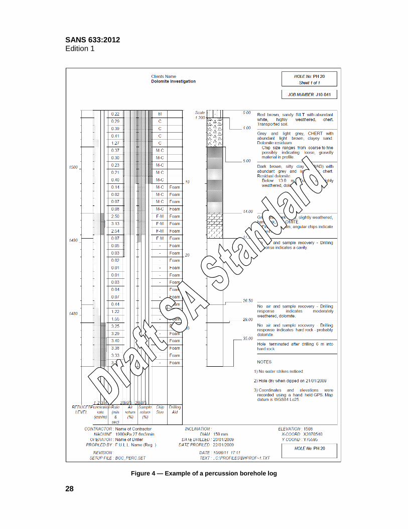
4.3.3.4.2 The initials, surname and professional registration of the profiler, the date profiled and the date excavated (if different), and relevant information from the drillers field report shall be stated beneath the soil profile (see figure 4). NOTE 1 No ground profile is complete unless the presence or absence of groundwater tables is referred to, and every profile record should indicate the depths and types of groundwater table. Where water is not encountered, a specific note should be made to this effect, but it should be observed that this does not necessarily mean that no groundwater table exists on the site. NOTE 2 The depth of caving, proximity of trees, proximity of watercourses, outcrop(s) close by, etc. should also be recorded. 4.3.3.4.3 Figure 4 provides a proforma percussion borehole log. Typical examples of the presentation of information are as follows: EXAMPLE 1 Grey and white, highly weathered chert with minor reddish brown silty sand. Talus. Chips show evidence of rounding indicating the presence of gravel in the profile. EXAMPLE 2 No air and sample return. Drilling response indicates hard rock – probably dolomite. EXAMPLE 3 Dark brownish grey, clayey silt (wad) with abundant angular chips of dark grey highly weathered chert. Residual dolomite. EXAMPLE 4 Grey and light grey slightly weathered (hard rock) dolomite with traces of translucent grey slightly weathered chert. Angular, medium sized chips and drilling response indicate hard rock.
SA
NS
633:2012
Edition 1
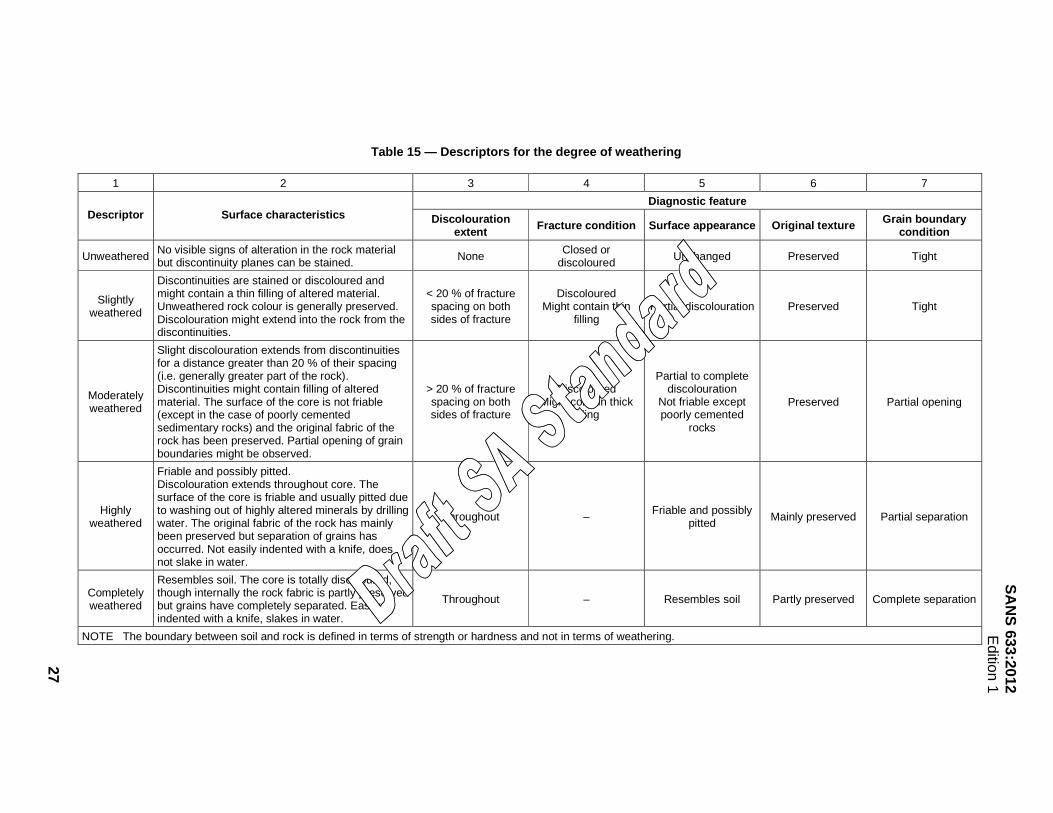
Table 15 — Descriptors for the degree of weathering
1 2 3 4 5 6 7
Diagnostic feature Descriptor Surface characteristics Discolouration
extent Fracture condition Surface appearance Original texture Grain boundary condition
Unweathered No visible signs of alteration in the rock material but discontinuity planes can be stained. None
Closed or discoloured Unchanged Preserved Tight
Slightly weathered
Discontinuities are stained or discoloured and might contain a thin filling of altered material. Unweathered rock colour is generally preserved. Discolouration might extend into the rock from the discontinuities.
< 20 % of fracture spacing on both sides of fracture
Discoloured Might contain thin
filling Partial discolouration Preserved Tight
Moderately weathered
Slight discolouration extends from discontinuities for a distance greater than 20 % of their spacing (i.e. generally greater part of the rock). Discontinuities might contain filling of altered material. The surface of the core is not friable (except in the case of poorly cemented sedimentary rocks) and the original fabric of the rock has been preserved. Partial opening of grain boundaries might be observed.
> 20 % of fracture spacing on both sides of fracture
Discoloured Might contain thick
filling
Partial to complete discolouration
Not friable except poorly cemented
rocks
Preserved Partial opening
Highly weathered
Friable and possibly pitted. Discolouration extends throughout core. The surface of the core is friable and usually pitted due to washing out of highly altered minerals by drilling water. The original fabric of the rock has mainly been preserved but separation of grains has occurred. Not easily indented with a knife, does not slake in water.
Throughout – Friable and possibly
pitted Mainly preserved Partial separation
Completely weathered
Resembles soil. The core is totally discoloured, though internally the rock fabric is partly preserved but grains have completely separated. Easily indented with a knife, slakes in water.
Throughout – Resembles soil Partly preserved Complete separation
NOTE The boundary between soil and rock is defined in terms of strength or hardness and not in terms of weathering.
27
SANS 633:2012 Edition 1
28
Figure 4 — Example of a percussion borehole log

SANS 633:2012 Edition 1
29
Table 16 — Descriptors of rock texture
1 2 3
Descriptor Size mm Field identification
Very fine grained < 0,2 Individual grains cannot be seen with a hand lens
Fine grained 0,2 – 0,6 Visible as individual grains under hand lens
Medium grained 0,6 – 2,0 Grains clearly visible under hand lens, just visible to the naked eye
Coarse grained 2,0 – 6,0 Grains clearly visible to the naked eye
Very coarse grained > 6,0 Grains measurable

SANS 633:2012 Edition 1
30
Annex A (informative)
The typical Southern African soil profile
A.1 The most characteristic feature of the typical Southern African soil profile is the widespread occurrence of a layer of gravel or decomposed gravel that has been designated the pebble marker. It lies between the transported soils above, and the residual soils below. First recognized, and named, in Vereeniging in 1949, it is the marker of alluvial pebbles between the un-stratified (transported alluvium) and the stratified (residual shale) soils of Vereeniging. The pebble marker was later found to occur in soil profiles over widespread areas of the country, even where alluvial soils were absent (see figure A.1).
B = Bedrock O = Pebble marker P = Pedogenic material (might be present, absent or weakly developed) R = Residual T = Transported
Figure A.1 — Possible combinations of rock, residual soils, transported soils and pedogenic material
A.2 Considerable care is necessary when identifying the pebble marker. Gravel layers are frequently encountered in the transported zone of the soil profile, and sometimes even in the residual zone, but it is only when a gravel layer is sandwiched between the transported and residual zones that it constitutes the pebble marker. To ensure that the proper gravel layer is found, at least one trial hole on every site should be sunk deep enough to identify the country rock or the residual products of decomposition of this rock. Working upwards, the pebble marker is then that gravel layer which is associated with the uppermost level of the residual materials. Once the pebble marker has been recognized in one trial hole in relation to the soils above and below it, it is comparatively easy to identify it in other holes on the same site. A.3 The pebble marker is not a regular stratigraphic stratum; it differs, both in age and in mode of origin, from one place to another. In one area it might be basal alluvial gravel constituting an ancient river terrace. In another, it might be a colluvial deposit of angular gravel transported down the pediment under the influence of gravity and rainwash. Such gravel bands, now possibly covered by wind-blown sands or other transported soils, might be early Pleistocene or even late Tertiary in age but on many pediments such deposits can be seen still forming today. In other cases, the pebble marker might even be a biogenic stone line, formed by the action of termites which have carried the finer particles of soil up to the surface to build their termitaries, leaving a concentration of particles of up to 2 mm in size below the surface.

SANS 633:2012 Edition 1
31
A.4 Although the pebble marker has been encountered over widespread areas, there are areas where the transported zone overlies the residual zone directly without the transition of a pebble marker. Even on a restricted site, the pebble marker might be present in some of the trial holes, and very poorly developed or even absent in others. In such cases, one should direct one’s attention primarily towards establishing the level at which transported soils meet residual soils, i.e. the level at which the pebble marker would have occurred had it been present. For example, in certain areas of the Free State Goldfields, there is evidence that the pebble marker did exist in former times, in the form of dolerite, shale and sandstone fragments overlying the Karoo sediments, but that these gravel fragments themselves have now weathered down into clays, silts and sands, respectively. A.5 From the engineering professional’s point of view, the pebble marker, representing the boundary between transported and residual soils, is of very great importance. First, it sometimes represents a stratum of free drainage which should be sealed off in certain forms of construction, such as dams or, if drainage is required, it may be retained and be usefully employed for providing a free flow of water. Secondly, it indicates the level below which soil behaviour may be approximately predicted from other experience with similar decomposed rock types. Geological information will also give the approximate stratigraphic thickness of the rocks concerned and whether the country rocks are of types which allow one to accept the principle that the degree of weathering will decrease with depth. In such a way, considerable subsoil information is provided without the need for deep and expensive boreholes.

SANS 633:2012 Edition 1
32
Bibliography A guide to core logging for rock engineering. Core Logging Committee, South African Section, Association of Engineering Geologists. Proceedings from the Symposium on Exploration for Rock Engineering Purposes. Johannesburg, 1976. Brink, ABA and Bruin, RMH (ed). Guidelines for soil and rock logging in South Africa. Proceedings of the Geoterminology Workshop 1990. Association of Engineering Geologists, South African Institution of Civil Engineering, and South African Institute for Engineering and Environmental Geologists. 2nd impression, 2002. Franki Africa (PTY) LTD. A guide to practical geotechnical engineering in Southern Africa. 4th ed, Johannesburg, December 2008. Jennings, JE, Brink, ABA, and Williams AAB. Revised guide to soil profiling for civil engineering purposes in Southern Africa. The Civil Engineer in South Africa, vol 15, No. 1. January 1973. Melis and Du Plessis. SAIEG, SAICE and AEG Geoterminology workshop. Proposed revisions to standard procedures for soil profiling. September 1990. Page,TC, Orr, CM, and Magni, ER. A borehole log for engineering purposes. Proceedings from the Symposium on Exploration for Rock Engineering Purposes. Johannesburg, 1976. South African Institution of Civil Engineering Geotechnical Division. Code of practice for the safety of persons working in small diameter shafts and testpits for geotechnical engineering purposes.
© SABS