704 Breakdown MC50
30
7/26/2019 704 Breakdown MC50 http://slidepdf.com/reader/full/704-breakdown-mc50 1/30 Insert document title Location | Date ATSB Transport Safety Report [Insert Mode] Occurrence Investigation XX-YYYY-#### Final Investigation Breakdown and subsequent drift towards danger of the bulk carrier ID Integrity Investigation Coral Sea | 18 to 23 May 2012 ATSB Transport Safety Report Marine Occurrence Investigation 294-MO-2012-005 Final – 22 August 2013
Transcript of 704 Breakdown MC50

7/26/2019 704 Breakdown MC50
http://slidepdf.com/reader/full/704-breakdown-mc50 1/30
Insert document title
Location | Date
ATSB Transport Safety Report
[Insert Mode] Occurrence Investigation
XX-YYYY-####
Final
Investigation
Breakdown and subsequent drift
towards danger of the bulk carrierID Integrity
Investigation
Coral Sea | 18 to 23 May 2012
ATSB Transport Safety Report
Marine Occurrence Investigation
294-MO-2012-005
Final – 22 August 2013

7/26/2019 704 Breakdown MC50
http://slidepdf.com/reader/full/704-breakdown-mc50 2/30
Released in accordance with section 25 of the Transport Safety Investigation Act 2003
Publishing information
Published by: Australian Transport Safety Bureau
Postal address: PO Box 967, Civic Square ACT 2608
Office: 62 Northbourne Avenue Canberra, Australian Capital Territory 2601
Telephone: 1800 020 616, from overseas +61 2 6257 4150 (24 hours)
Accident and incident notification: 1800 011 034 (24 hours)Facsimile: 02 6247 3117, from overseas +61 2 6247 3117
Email: [email protected]
Internet: www.atsb.gov.au
© Commonwealth of Australia 2013
Ownership of intellectual property rights in t his publication Unless otherwise noted, copyright (and any other intellectual property rights, if any) in this publication is owned bythe Commonwealth of Australia.
Creative Commons li cence With the exception of the Coat of Arms, ATSB logo, and photos and graphics in which a third party holds copyright,this publication is licensed under a Creative Commons Attribution 3.0 Australia licence.
Creative Commons Attribution 3.0 Australia Licence is a standard form license agreement that allows you to
copy, distribute, transmit and adapt this publication provided that you attribute the work.
The ATSB’s preference is that you attribute this publication (and any material sourced from it) using the
following wording: Source: Australian Transport Safety Bureau
Copyright in material obtained from other agencies, private individuals or organisations, belongs to those
agencies, individuals or organisations. Where you want to use their material you will need to contact them
directly.
Add end um
Page Change Date

7/26/2019 704 Breakdown MC50
http://slidepdf.com/reader/full/704-breakdown-mc50 3/30
Safety summary
What happened
In the early hours of 18 May 2012, while transiting the Coral Sea, ID Integrity’s main engine shut
down when its fuel pump reversing mechanism came free and jammed. This caused the camshaft
to bend and slip in a drive coupling which resulted in the camshaft being out of timing and
therefore the engine could not be restarted.
The ship drifted in a westerly direction towards the Australian coast and the Great Barrier Reef.
During the afternoon of 19 May, the ship passed over Shark Reef, located about 60 miles east of
the Great Barrier Reef Marine Park, without incident. The following day, the ship was taken in tow
when it was about 35 miles to the east of the marine park and towed to Cairns for repairs.
What the ATSB foundThe ATSB found that the engine manufacturer had identified the need for owners and operators to
check the fuel pump reversing mechanism for cracks and secureness and provided this advice in
service letters. However, on board ID Integrity, this advice had not been included in the engine
manuals or planned maintenance system. As a result, over time and despite regular inspections,
the system deteriorated and cracks developed in the mechanism undetected. This led to the
failure of a fuel pump reversing link on 18 May.
The investigation also found that, once notified, the actions of the various stakeholders were
appropriate and the response arrangements were effective.
What's been done as a resultID Integrity’s managers have implemented a schedule to inspect all main engines in their fleet and
undertake repairs as necessary. Staff from all company ships have been made aware of this
incident and it has been included in crew training centre courses.
MAN B&W, the main engine designer, reiterated the need to include all service letter advice in
manuals and maintenance systems. They also advised that service letters and updated manuals
are always available on request through the website http://www.mandieselturbo.com via the
Nexus (Customer extranet) link.
The ship’s classification society, ClassNK, initiated discussions with MAN B&W to enhance its
knowledge of engine design and operation changes. ClassNK also improved the content and
extent of information provided to its surveyors.
Safety message
Service advice from machinery manufacturers needs to be carefully assessed and implemented
as necessary as part of a ship’s planned maintenance system. Furthermore, all associated
documentation should be updated and regularly checked to ensure it remains relevant and reflects
the latest available information.

7/26/2019 704 Breakdown MC50
http://slidepdf.com/reader/full/704-breakdown-mc50 4/30
Contents
The occurrence ........................................................................................................................1
Context ......................................................................................................................................7
ID Integrity 7
Crew 7
Main engine 8
Auxiliary machinery 9
Main engine breakdown 9
Diesel generator breakdowns 10
The Great Barrier Reef and Marine Park 11
Shark Reef 11
Australian response arrangements 12
Response to the drifting ID Integrity 13
Safety analysis ...................................................................................................................... 15
Main engine maintenance 15
Service letters 15
Maintenance guidance 15
On board maintenance 16
Class requirements 17
Findings ................................................................................................................................. 19
Contributing factors 19
Other factors that increase risk 19
Other findings 19
Safety issues and actions ................................................................................................... 20
On board planned maintenance system 20
Safety issue description: 20
Class requirements 20
Safety issue description: 21
General details ...................................................................................................................... 22
Occurrence details 22
Ship details 22
Sources and submissions .................................................................................................. 23
Sources of information 23
References 23
Submissions 23
Austral ian Transport Safety Bureau .................................................................................. 24
Purpose of safety investigations 24
Developing safety action 24

7/26/2019 704 Breakdown MC50
http://slidepdf.com/reader/full/704-breakdown-mc50 5/30
ATSB – 294-MO-2012-005
› 1 ‹
The occurrenceOn 5 May 2012, the 185.74 m geared bulk carrier ID Integrity (Figure 1) departed from Shanghai,
China. The ship was in ballast and bound for Townsville, Australia, where it was to load a cargo of
sugar.
The ship travelled south through the western Pacific Ocean toward the northern coast of Papua
New Guinea. During this time, the crew carried out an exchange of the ship’s ballast water 1 in
accordance with Australian ballast water management requirements. This process took about
3 days and required the running of two of the ship’s three diesel generators.
While running two diesel generators, the ship’s engineers found that diesel generator numbers
2 (DG2) and 3 (DG3) could not carry the required load, so they dismantled and cleaned the
turbochargers of both engines. The turbochargers were found heavily contaminated with carbon.
In the days following this maintenance, DG2 was used to supply all the ship’s electrical needs.
Figure 1: ID Integrity as it drif ted across Shark Reef
Source: Australian Maritime Safety Author ity
At about 06002 on 14 May, when the ship was in the Vitiaz Strait on the northern coast of Papua
New Guinea (Figure 2), DG2 shutdown without warning, the ship lost all electrical power (blacked
out) and the main engine stopped. The engineers restored electrical power by starting diesel
generator number 1 (DG1) and DG3 and the voyage was continued. Upon investigation, the
engineers found DG2’s turbocharger rotor shaft had broken. Since there was no spare on board,
the turbocharger could not be repaired and the generator was not run. The engineers left the
remaining two diesel generators running in the belief that running two generators in parallel on low
load provided more security of power supply than one generator running alone on higher load.
At 2200 on 15 May, ID Integrity passed through Jomard Passage (Figure 2) and entered the Coral
Sea. The weather was now from the southeast at force3 7 (28 to 33 knot
4 winds with wave heights
1 Ballast consists of heavy material (commonly sea water) loaded on board a ship to improve its stability and rideconditions.
2
Unless otherwise stated, all times in this report are local time, UTC +10 hours.3 The Beaufort scale of wind force, developed in 1805 by Admiral Sir Francis Beaufort, enables sailors to estimate windspeeds through visual observations of sea states.
4 One knot, or one nautical mile per hour, equals 1.852 kilometres per hour.

7/26/2019 704 Breakdown MC50
http://slidepdf.com/reader/full/704-breakdown-mc50 6/30
ATSB – 294-MO-2012-005
› 2 ‹
of 4 to 5.5 m). The master contacted the Australian Rescue Coordination Centre (RCC)5 and
made an initial Australian Ship Reporting System (AUSREP) report.
Figure 2: Section of navigational chart Aus4060 showing ID Integrity ’s t rack, 14 to 22 May
Source: Australian Hydrographic Service
At about 0930 on 16 May, in position 13° 16.5' S 150° 46.3' E, both diesel generators
unexpectedly stopped when they were unable to carry the electrical load. The ship blacked out,
the main engine stopped and the emergency generator automatically started, providing
emergency power. Without propulsion, the ship turned beam on to the weather and swell, began
to roll heavily and to drift in a westerly direction.
DG3’s turbocharger was dismantled and cleaned and the engine put back into operation. DG1’s
turbocharger was also dismantled, however, the engineers found the bearings had failed.
Because there were no spares remaining on board, the turbocharger could not be repaired. In an
5 The RCC is an operational unit of the Australian Maritime Safety Authority (AMSA).
7/26/2019 704 Breakdown MC50
http://slidepdf.com/reader/full/704-breakdown-mc50 7/30
ATSB – 294-MO-2012-005
› 3 ‹
effort to provide backup electrical power to support DG3, and as DG2’s turbocharger was already
dismantled, the engineers decided to run DG2 normally aspirated.6
At about 2000 on 16 May, the main engine was started, but it could not be run up to full speed
because the number two cylinder air start valve was stuck open. The engine was shut down to
repair the air start valve, but the engineers could not repair it in place and were unable to removeit from the engine as it was stuck fast in the cylinder head.
By the morning of 17 May, the air pipe leading to the faulty air start valve had been blanked off.
The main engine was started, but this time its number six cylinder was not firing and the engine
would not reach full speed. The main engine was shut down again and, after some consultation
with the company’s shore-based technical superintendent, the engineers replaced the number six
cylinder fuel valves (injectors) and the fuel pump delivery valve.
During this time, the ship continued to drift in a westerly direction, rolling heavily in the rough seas.
At 1218, the master made an AUSREP deviation report.7 He noted that the ship was stopped due
to main engine problems and was drifting in a westerly direction at 3 knots. It was 150 miles8 from
the nearest danger (Willis Islets to the south) and about 310 miles northeast of Cairns,Queensland. The master provided further information to the RCC as the day progressed.
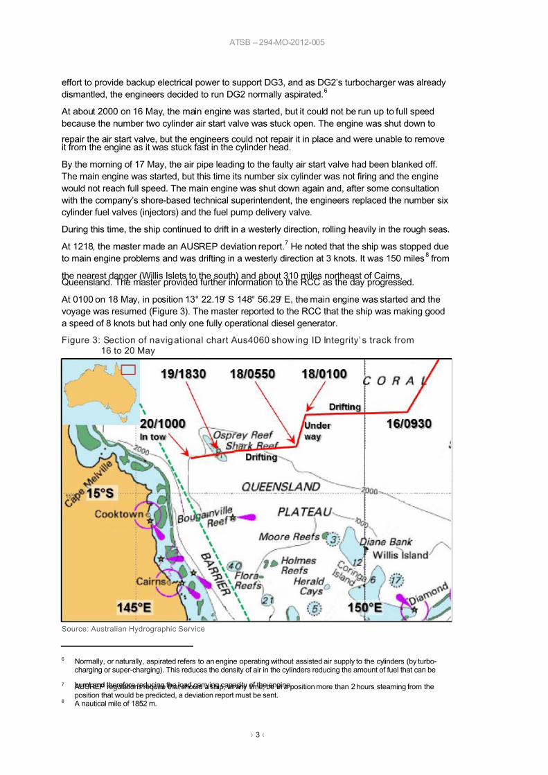
At 0100 on 18 May, in position 13° 22.19' S 148° 56.29' E, the main engine was started and the
voyage was resumed (Figure 3). The master reported to the RCC that the ship was making good
a speed of 8 knots but had only one fully operational diesel generator.
Figure 3: Section of navigational chart Aus4060 showing ID Integrity’ s track from16 to 20 May
Source: Australian Hydrographic Service
6 Normally, or naturally, aspirated refers to an engine operating without assisted air supply to the cylinders (by turbo-charging or super-charging). This reduces the density of air in the cylinders reducing the amount of fuel that can be
burnt and therefore reducing the load carrying capacity of the engine.7 AUSREP regulations require that should a ship, at any time, be in a position more than 2 hours steaming from theposition that would be predicted, a deviation report must be sent.
8 A nautical mile of 1852 m.

7/26/2019 704 Breakdown MC50
http://slidepdf.com/reader/full/704-breakdown-mc50 8/30
ATSB – 294-MO-2012-005
› 4 ‹
At about 0550, in position 14°00.66' S 148°30.87' E, the main engine stopped again. No alarm
sounded and the duty engineer could not identify a fault.
The chief engineer was called and the engine room staff began searching for the cause of the
shutdown. In the heavy seas, there had been repeated lubricating oil pressure alarms so attention
was initially turned to verifying the integrity of the main engine lubrication system. No problemswere found and several unsuccessful attempts were made to restart the main engine.
At 0859, the master reported to the RCC that the ship was drifting, with an expected stoppage
time of about 3 hours. The RCC began to monitor ID Integrity’s progress. The ship was in no
immediate danger (about 100 miles to the east of Osprey Reef) and the engineers continued to
search for the cause of the main engine stoppage.
At 1815, the master contacted the RCC and reported that the ship was in position 14° 05’ S
148° 00’ E and that the main engine could not be started. The ship was drifting in a westerly
direction at about 3 knots and would be closing on Shark Reef in about 20 hours.
The Australian Maritime Safety Authority (AMSA) activated the Australian National Maritime
Emergency Response Arrangements (NMERA) which included assessing the availability of towingresources. AMSA advised ID Integrity’s managers, ID Wallem Ship Management, of this action
and the company began making arrangements to source other suitable towing vessels to assist.
AMSA kept stakeholders, including Maritime Safety Queensland (MSQ), the Great Barrier Reef
Marine Park Authority (GBRMPA), the Great Barrier Reef and Torres Strait Vessel Traffic Service
(REEFVTS), insurers and ID Wallem appraised of the situation. AMSA also assessed the ship’s
drift and tasked the emergency towage vessel Pacific Responder 9 to assist. At the time, Pacific
Responder was in the Torres Strait, about 350 miles to the northwest and was expected to arrive
at ID Integrity’s position late in the afternoon of 20 May.
In the meantime, the ship’s managers negotiated a commercial towage agreement and, on
19 May, two tugs were dispatched to assist ID Integrity. PT Kotor , a 23.5 m tug departed from
Mourilyan (south of Cairns) and was expected to rendezvous with ID Integrity during the morning
of 20 May. The 28.7 m tug PB Leichhardt departed from Townsville with an estimated arrival at
the ship’s position during the evening of 20 May.
ID Integrity’s engineers, in consultation with ID Wallem’s technical superintendent, continued to
search for the cause of the main engine stoppage. While inspecting the engine, the engineers
were slowly turning the engine using the turning gear 10
when the turning gear drive motor
overloaded and tripped out. The chief engineer concluded that there was a physical obstruction in
the engine that was causing an increased resistance to turning, so he decided to inspect the
rotating components of the engine, starting with the camshaft. Upon removal of the camshaft
cover from number six cylinder, he found pieces of the fuel pump cam, fuel pump roller and
reversing mechanism (Figure 4). Closer inspection showed damage to the cam and engine block
surfaces (Figures 5, 6 and 7).
The engineers cleaned the debris out of the camshaft space and began preparing to lift the
number six fuel pump off the cam so they could attempt to run the main engine on the remaining
five cylinders.
9 Pacific Responder is an Anchor Handling Tug Supply (AHTS) vessel modified to fulfil the role of AMSA’s dedicated
emergency towage vessel (ETV). This is the only ETV of its type in Australia and operates in the particularly sensitivesea areas of the northern Great Barrier Reef and Torres Strait..10 A reversible electric motor connected through a worm gear drive to the toothed flywheel of the main engine to allow
slow turning of the engine.

7/26/2019 704 Breakdown MC50
http://slidepdf.com/reader/full/704-breakdown-mc50 9/30
ATSB – 294-MO-2012-005
› 5 ‹
Meanwhile, ID Integrity continued to drift in a westerly direction towards Shark Reef.
At 1305 on 19 May, the master reported to the RCC that the ship was rolling heavily in 2.5 to 3 m
seas and 35 to 40 knot winds from the southeast. It was still drifting in a westerly direction at 3
knots and was about 14 miles from Shark Reef.
As none of the tugs would reach the ship before it was likely to pass over Shark Reef, other
contingencies, including the use of the ship’s anchors, were considered. It was agreed that the
master would de-ballast the ship to reduce its aft draught to 5.0 m, increasing the ship’s under
keel clearance to the maximum possible. The minimum charted depth for Shark Reef is 8.1 m.
Figure 4: Pieces removed from camshaftspace
Source: ATSB
Figure 5: Fuel pump cam and engine blockdamage
Source: ID Wallem
Figure 6: Fuel pump cam damage
Source: MAN Diesel & Turbo
Figure 7: Damage to rol ler guide housing
Source: MAN Diesel & Turbo
At about 1830, ID Integrity drifted across the southern end of Shark Reef in waters about 20 m
deep, about 4 miles south of the charted 8.1 m depth. ID Integrity was now about 60 miles from
the eastern edge of the Great Barrier Reef Marine Park and was expected to close on it in less
than 24 hours.
At 0900 on 20 May, PT Kotor rendezvoused with ID Integrity and in the rough seas it took about
an hour to connect a tow line. ID Integrity’s bow was then turned into the weather allowing it to ride
more easily and its drift was arrested. The tug and tow moved in a south-easterly direction.
At 1715, Pacific Responder arrived at ID Integrity’s position and, with darkness approaching,
stood-by until the following morning. PB Leichhardt arrived later that evening.
During the morning of 21 May, Pacific Responder took over the tow and at 0815, with the othertugs as escorts, commenced towing ID Integrity toward Cairns.

7/26/2019 704 Breakdown MC50
http://slidepdf.com/reader/full/704-breakdown-mc50 10/30
ATSB – 294-MO-2012-005
› 6 ‹
At 0635 on 23 May, two pilots boarded the ship and guided the tow through the Grafton Passage
and towards Cairns. By 1500, the ship was safely anchored off Cairns, and the tugs had been
released.
While ID Integrity was at anchor, the main engine and generators were repaired. On 27 June, the
ship sailed for Port Moresby, Papua New Guinea, where further repairs were carried out.
7/26/2019 704 Breakdown MC50
http://slidepdf.com/reader/full/704-breakdown-mc50 11/30
ATSB – 294-MO-2012-005
› 7 ‹
Context
ID Integrity
Crew
ID Integrity had a crew of 23 Indian and Myanmar nationals, all of whom were appropriately
qualified for the positions they held on board the ship. Apart from the chief engineer, all the crew
had joined the ship 4 months prior to the incident, in February 2012, when ID Wallem Ship
Management had changed the ship’s crew from predominantly Chinese crew to predominantly
Indian crew.
The master had about 22 years of seagoing experience. He held an Indian master’s certificate of
competency and had been sailing as master since 2002. This was his first voyage on ID Integrity
and his first with ID Wallem Ship Management.
The chief engineer first went to sea in 1978. He obtained his Myanmar chief engineer’s certificatein 1992 and had been sailing as chief engineer since 1996. This was his first ship and contract
with ID Wallem Ship Management. He had joined ID Integrity 3 months before this incident.
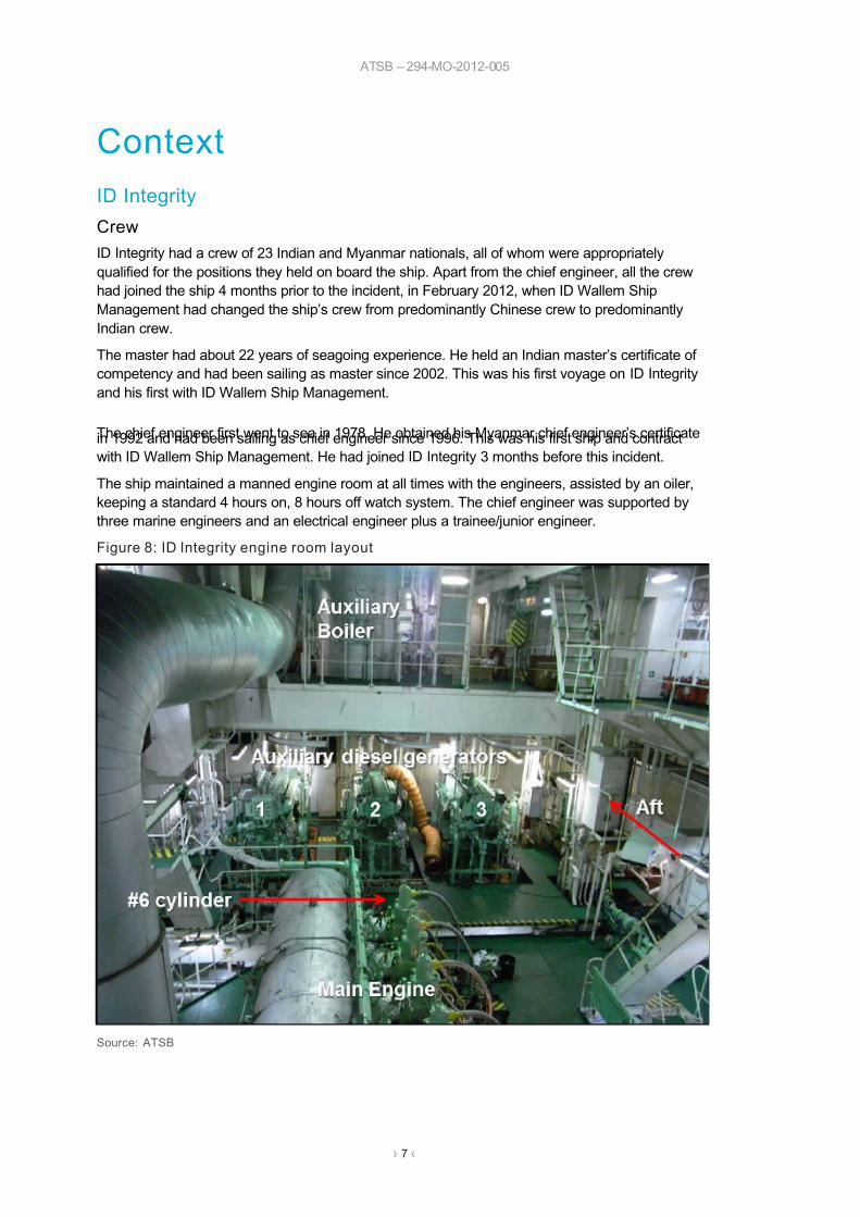
The ship maintained a manned engine room at all times with the engineers, assisted by an oiler,
keeping a standard 4 hours on, 8 hours off watch system. The chief engineer was supported by
three marine engineers and an electrical engineer plus a trainee/junior engineer.
Figure 8: ID Integrity engine room layout
Source: ATSB

7/26/2019 704 Breakdown MC50
http://slidepdf.com/reader/full/704-breakdown-mc50 12/30
ATSB – 294-MO-2012-005
› 8 ‹
Main engine
The ship is fitted with a MAN B&W 6S50MC Mk5, six cylinder, two stroke, reversible slow speed
diesel engine which delivers 7,465 kW at 122 rpm (Figure 8). The engine was built by Mitsui
Engineering and Shipbuiliding, Japan, under licence from the engine designer, MAN B&W Diesel
and Turbo Copenhagen (MAN B&W), Denmark. The engine drives a single, fixed pitch propeller,giving the ship a service speed of about 14.1 knots. At the time of the incident, the main engine
had recorded 86,907 run hours since new and 6,186 run hours since the last major maintenance
had been completed on the camshaft and reversing systems. Records showed that the engine’s
components had been surveyed as per Nippon Kaiji Kyokai (ClassNK) 11
requirements.
The camshaft in the six cylinder MC-type engine is driven from the crankshaft by a chain. It is
made up of a number of camshaft segments coupled together, each segment holding the exhaust
valve and fuel pump cams required for two main engine cylinders.
Each main engine cylinder has its own fuel pump mounted on the roller guide housing over the
camshaft segment corresponding to that cylinder. Rotating motion of the camshaft is converted to
vertical reciprocating motion in the fuel pump through the fuel pump roller and guide (Figure 9).
Figure 9: MAN B&W fuel pump, cam, roller, guide and reversing arrangement
Source: MAN Diesel & Turbo Australia
The fuel pump roller guide slides in a guide bushing (liner) which is fastened in the roller guide
housing. The guide bushing includes a guide block (plate) which prevents the roller guide from
turning about the vertical axis of the fuel pump during reversing of the engine.
11 Nippon Kaiji Kyokai, known as ClassNK, is a ship classification society.

7/26/2019 704 Breakdown MC50
http://slidepdf.com/reader/full/704-breakdown-mc50 13/30
ATSB – 294-MO-2012-005
› 9 ‹
Each cylinder is individually reversed by shifting the roller in the fuel pump drive mechanism. The
link connecting the roller guide and roller is provided with a reversing arm, connected to an air
cylinder. The link is self-locking in either the ahead or astern position without the aid of external
forces. Sensors are fitted to the air cylinder to provide feedback of the roller position to the engine
monitoring and control system.
Auxi liary machinery
The ship’s electrical power was provided by three Yanmar 6M-200L-SN diesel engines driving
direct coupled 440 kW, 60 Hz Taiyo electrical generators at 720 rpm. The engines were designed
to run on varying grades of fuel oil up to a viscosity of about 700 cSt.12
However, they were to use
marine diesel oil (a higher grade of fuel of lower viscosity and not requiring heating for use) when
starting and for running at less than 30 per cent load.
At the time of the incident, the main engine and diesel generators were operating on 380 cSt
intermediate fuel oil (IFO380). The fuel oil viscosity controller was not operational and, as a result,
fuel viscosity for all engines was controlled manually based upon the fuel oil inlet temperature to
the main engine. An independent analysis of bunker fuel samples taken at the time the fuel wasreceived on board included recommended fuel temperatures for injection viscosities. This analysis
had determined that this fuel was ‘above average’ in quality and sufficient quantity was on board
for the voyage to Australia.
Main engine breakdown
When the ship’s engineers discovered the broken pieces of fuel cam reversing mechanism under
number six fuel pump, it was apparent to them that the damage to the main engine was more
extensive than just the fuel pump cam and fuel pump roller reversing and guide assemblies. While
the ship was at anchor off Cairns, technical staff from ID Wallem Ship Management and service
personnel from MAN B&W attended the ship to conduct an inspection and to carry out repairs.
The initial MAN B&W inspection report found that:
The No. 6 fuel roller guide has failed and caused damage [to] the fuel cam for unit13
6 which
has caused the camshaft to slip 190 degrees in the after most coupling. The resulting
mistiming of all cylinders rendered the engine unable to be started.
The fuel pump guide plate for units 1, 2, 3 and 4 were found loose and the bolts and pins
were found broken.
and
The run out between the fuel cam and bearing for unit 6 was measured … indicating the
[cam]shaft was bent.
MAN B&W subsequently stated that the engine failure was not caused by the loose number sixfuel pump cam follower roller guide block and that, historically, loose guide blocks had not
significantly affected the operation and reversing of engines. This opinion was further supported
by the discovery that four of the remaining five guide blocks in ID Integrity’s engine were also
loose but had not affected the running of the engine.
MAN B&W also stated that the reversing mechanism generally, and in particular cylinders 1 and 6,
was in poor or non-operational condition and would not have worked as intended. Cracks were
found in all reversing links. MAN B&W stated that it is likely that the number six reversing link
broke, causing interference and jamming of the fuel cam in the engine frame. This, they
suggested, was as a result of operation of the engine with a malfunctioning reversing mechanism
which led to overstressing of the reversing link, its failure and resultant jamming of the camshaft.
12 CentiStoke, or cSt, is a measure of the kinematic viscosity of a liquid.13 ‘Unit’ is a marine engineering term used interchangeably with cylinder

7/26/2019 704 Breakdown MC50
http://slidepdf.com/reader/full/704-breakdown-mc50 14/30
ATSB – 294-MO-2012-005
› 10 ‹
It is possible that, in the early hours of 18 May, after many days of long hours repairing the main
and diesel generator engines, in adverse weather, and often in blackout conditions, the ship’s
engineers did not verify that all main engine fuel pump cam followers were in the correct, locked
position for the duration of main engine operation that morning.
However, several safeguards were built into the engine room monitoring and control systems tominimise the likelihood of this occurring. The main engine monitoring system included an alarm
(audible and visual) for any fuel cam abnormality—that is, if any of the six fuel pump roller guides
were not in the correct position corresponding to the direction of rotation of the engine this alarm
activated. Further, the main engine control console (and the engine side control station) included
indicator lamps for fuel cam position—ahead or astern—which illuminated only when all of the fuel
cams were in the same position. In addition to these safeguards, the position of each fuel pump
was physically indicated on the back of the fuel pump by the position of the reversing cylinder
shaft. These indicators should have been checked as part of routine engine room checks soon
after starting of the main engine. Operating parameters recorded during the period of main engine
operation on the morning of 18 May showed the main engine to be operating satisfactorily with no
clear indication of any abnormality.
After considering the evidence available, the ATSB concluded that cracks had developed in
several reversing links and guide rollers over the life of the ship, possibly due to repeated events
in which the engine had been operated with fuel pump roller guides in the wrong position.
It is also possible that the lack of firing in number six unit on the morning of 17 May may have
been attributable to the later identified fuel pump cam follower failure. However, the actions taken
by the ship’s crew, replacing the fuel valves and the fuel pump delivery valve, appeared to rectify
the non-firing issue at the time and were probably reasonable in the circumstances.
Diesel generator breakdowns
All three diesel generator turbochargers were overhauled in September/October 2011 and recordsindicate that they had operated trouble free for the previous 12 months.
In January 2012, DG2’s turbocharger rotor failed. In February 2012, when the new crew joined
ID Integrity they were still awaiting spare parts for the turbocharger. On 14 March 2012, the
turbocharger and engine were rebuilt and put back into service.
In the following 2 months (to 14 May), both DG2 and DG3’s turbochargers were stripped and
cleaned twice each. Then, on 14 May, DG2’s turbocharger failed due to a broken rotor shaft and,
on 16 May, DG1 and DG3 shutdown due to fouled turbochargers.
During this time, the engineers concentrated their efforts on rectifying the symptom, the fouled
turbochargers, rather than identifying and rectifying the actual cause of the turbocharger fouling.
The fuel analysis indicated that the fuel in use at the time was of above average quality and henceshould not have been a contributing factor to the fouling. However, the diesel generators were
regularly operated for extended periods of time at less than 30 per cent load while using heavy
fuel oil, contrary to the manufacturer’s instructions.
It is likely that, as a result of prolonged periods of operation at reduced load, the cylinder bores
and piston ring faces had become glazed. This probably led to poor sealing of piston rings to
cylinder liner resulting in carry-over of lubricating oil into the exhaust system (Figure 10).
Furthermore, operating the engines on heavy fuel at low loads probably resulted in poor
combustion and carry-over of unburnt fuel. It is also possible that oil entered the exhaust system
through leaking valve guide seals in the cylinder head. Together, these conditions probably led to
the fouling of the turbochargers.

7/26/2019 704 Breakdown MC50
http://slidepdf.com/reader/full/704-breakdown-mc50 15/30
ATSB – 294-MO-2012-005
› 11 ‹
Figure 10: Number 3 diesel generator turbocharger, May 2012
a) Fouled turbocharger nozzle ring b) Turbocharger exhaust inlet pipes
Source: ID Wallem Source: ID Wallem
The Great Barrier Reef and Marine Park
The Great Barrier Reef (GBR) is the world’s largest coral reef ecosystem with vast areas of reefs,
shoals and numerous islands (Figure 11). It extends over 1,400 miles almost parallel to the
Queensland coast and is up to 35 miles wide, between 8 and 80 miles offshore and contains over
2,900 reefs and 900 islands. The GBR and islands in the area form a natural breakwater at
varying distances from the coastline. A number of openings or passages exist through the reefs
and between islands.
The World Heritage listed GBR has long been recognised as an environmentally sensitive area.
Since the establishment of the Great Barrier Reef Marine Park in 1975 measures to protect the
area have been progressively implemented. The focus of all existing protective measures iscentred on preventing environmental damage, particularly due to a shipping incident.
The Great Barrier Reef Marine Park encompasses most of the world heritage area and covers
about 344,000 km² along the Queensland coast. It is managed by the Great Barrier Reef Marine
Park Authority (GBRMPA) whose objective is to protect the park by controlling human activity and
by maintaining the natural functions of the ecosystem. The park extends from the low water mark
of the northern tip of Cape York, south to latitude 24°30’ S about 40 miles south of Gladstone .
Shark Reef
Shark Reef is part of the Osprey group of reefs (Osprey, Shark and Vema Reefs) located about
100 miles north-east of Cape Flattery and about 60 miles from the outer limit of the boundary of
the GBR marine park. The reefs form an important ecological, research and dive location in the
Coral Sea.
The Australia Pilot14
describes Shark Reef as:
Shark Reef, with a least known depth of 8.1 m over it, lies at the NW end of a bank, 8 miles
SE of Rapid Horn [Osprey Reef]. The reef is a narrow ridge of coral, 1 mile in length, and is
not easily seen from any distance. The bank has general depths less than 20 m over it and
is steep-to.
Osprey Reef:
… extends… 15 miles NNW, and encloses a lagoon which has an entrance near the middle
of the W side… In strong SE winds seas break heavily on the SE side of the reef…
14 Admiralty Sailing Directions, Australia Pilot Volume III (NP15), eleventh edition, 2009, p82

7/26/2019 704 Breakdown MC50
http://slidepdf.com/reader/full/704-breakdown-mc50 16/30
ATSB – 294-MO-2012-005
› 12 ‹
Vema Reef:
… with a least known depth of 11.5 m over it, lies on a separate bank 7 miles farther SE [of
Shark Reef].
Figure 11: The Great Barrier Reef and the area of the incident
Source: Great Barrier Reef Marine Park Authority
Australian response arrangements
Australia maintains a number of plans and services aimed at providing emergency assistance andsearch and rescue (SAR) capabilities for ships visiting Australia or transiting Australian waters.
The Australian Maritime Safety Authority (AMSA) is the national safety agency responsible for
maritime safety, protection of the marine environment and aviation and marine search and rescue.
Australia has accepted search and rescue responsibility for a large region surrounding Australia,
into the Indian Ocean and south to the coast of Antarctica. AMSA delivers this SAR service by
maintaining the Rescue Coordination Centre (RCC) which coordinates both maritime and aviation
search and rescue.
AMSA, through the RCC, also operates the Australian Ship Reporting System (AUSREP)15
which,
as a source of ship position data, provides a positive SAR watch for all participants in the system.
If a ship within the system fails to fulfil the daily (24 hour) reporting requirements, the RCC will
15 See http://www.amsa.gov.au/Shipping_Safety/AUSREP/ for information regarding AUSREP.

7/26/2019 704 Breakdown MC50
http://slidepdf.com/reader/full/704-breakdown-mc50 17/30
ATSB – 294-MO-2012-005
› 13 ‹
initiate communication checks to establish the reason for the failure and to check if the ship and
crew are safe. If the checks are unsuccessful, a search will be initiated using air and available
nearby shipping.
Once aware of an incident or emergency the response of the RCC will vary depending upon the
circumstances. In the case of a disabled ship off the coast of Australia, while the prime concern isensuring the safety of the ship and crew, other efforts are directed toward protecting the
environment and coastline from damage and pollution. The potential consequences of such an
incident require a rapid and effective response. To this end, Australia has established the National
Maritime Emergency Response Arrangements (NMERA)16
with an integrated national approach
involving an emergency towage capability in strategic locations around the Australian coastline.
Under the NMERA, a number of emergency towage vessels (ETVs) are located in strategic
Australian coastal regions. These ETVs provide an emergency towage capability to deal with a
significant, or potentially significant, threat to Australia’s marine environment. In the Torres Strait
and Great Barrier Reef area north of Cairns, a dedicated ETV (Pacific Responder ) provides
emergency towage and first response capability.
Response to the drifting ID Integrity
At 1218 on 17 May, ID Integrity’s master reported the ship was stopped due to main engine
problems and was drifting in a westerly direction. The RCC monitored the situation until the
master reported that the ship was underway. At that stage, the almost 40 hour stoppage17
presented no danger to the ship or the environment as it had occurred in the Coral Sea, well to the
east and north of any islands, reefs or the mainland of Australia.
Subsequently, at 0859 on 18 May, the master reported that ID Integrity was again stopped and
drifting. At 1815, he reported that the crew were still unable to start the main engine. The ship was
now further to the south and west of the earlier incident and much closer to areas of significance
and danger.
The master had identified the ship’s drift rate and direction and that the likely nearest point of
danger (Shark Reef) was about 20 hours away. In response, AMSA activated the NMERA and
tasked Pacific Responder . Discussions with the master, the ship’s managers and insurers also led
to the ship’s managers engaging two tugs to assist the ship. Other stakeholders were briefed and
ships in the area alerted.
At 1830 on 19 May, ID Integrity, with an under keel clearance of about 15 m, drifted across Shark
Reef without incident. At 1000 the following day, in position 14° 14.71’ S 146° 16.84’ E, about
35 miles from the outer edge of the GBR marine park, the ship was taken in tow.
On 17 May, the master’s actions when responding to the unfolding situation were appropriate.
Then, on 18 May, after the ship lost propulsion, he again alerted the RCC to the breakdown and
subsequently that the ship was without its main engine, was drifting and would need assistance.
There were about 12 hours from the time the main engine stopped to the master informing the
RCC that the ship was disabled. However, this time was necessary to determine the extent of the
breakdown and to establish that the ship was in fact disabled, could not continue under its own
power and was in need of assistance. Given the recent history of machinery breakdowns and the
proximity to Shark Reef, notification of authorities at the earliest opportunity was required to give
them sufficient time to activate towage and other response measures. As it was, the earliest tug to
arrive at ID Integrity, PT Kotor , arrived more than 15 hours after the ship crossed Shark Reef.
Even taking into account the time needed to determine the status of the main engine, there was
insufficient time for tug assistance to arrive at ID Integrity’s position before it crossed Shark Reef.
16 For more information refer to http://www.amsa.gov.au/Marine_Environment_Protection/17 Duration calculated using ship recording not reporting times.

7/26/2019 704 Breakdown MC50
http://slidepdf.com/reader/full/704-breakdown-mc50 18/30
ATSB – 294-MO-2012-005
› 14 ‹
The subsequent actions of the various parties were measured and appropriate and the
emergency response arrangements were effective. While Shark Reef is isolated and tugs arrived
to assist ID Integrity after the ship had passed over the reef, they arrived well before the ship could
drift into the Great Barrier Reef Marine Park.

7/26/2019 704 Breakdown MC50
http://slidepdf.com/reader/full/704-breakdown-mc50 19/30
ATSB – 294-MO-2012-005
› 15 ‹
Safety analysis
Main engine maintenance
The operation and maintenance of ID Integrity’s MAN B&W MC-type main engine was supported
by a suite of manuals and drawings covering the operation, maintenance and spare parts
requirements of the engine. Engine owners and operators were also provided with worldwide
sales, spare parts, technical service and customer support networks.
Service letters
As part of a program of continual improvement, and to supplement the engine manuals and
documents supplied with an engine, the engine designer (MAN B&W), in consultation with the
engine manufacturer (in this case Mitsui Engineering and Shipbuilding), from time to time as
necessary, release service letters. These letters provide up-to-date information and guidance
based on accumulated service experience and describe issues which have become apparent
regarding the design, maintenance or operation of the type of engine to which the letter applies.The letters may also include the revision of instructions and overhaul intervals and may supersede
originally supplied documents and/or instructions.
Such letters are distributed to all known owners and operators of MC-type engines. MAN B&W
expects that any revised documents and instructions are included in the on board engine manuals
and maintenance systems. In addition, any such revisions are coded differently to those originally
supplied and copies are provided with the service letter or component to which they relate. The
original on board manuals also included the advice that new service letters could be of great
importance and recommended that they be filed in the appropriate section of the manuals.
MAN B&W also advise that service letters are available on the internet through the website
www.mandieselturbo.com via the Nexus (Customer extranet) link. Further, they advised that
updated and revised instruction books are available on request.
Maintenance guidance
The advice provided in the original main engine operating manual was inspection of the fuel pump
and camshaft arrangements, including the reversing mechanism, every 8,000 operating hours
with overhaul of the mechanism as necessary. The maintenance manual procedure for this
overhaul included directions for the disassembly and overhaul of the roller guide and for checking
the roller guide plate clearances.
In 1988, MAN B&W issued a service letter discussing operator experience with the reversing
mechanisms of MC/MCE engines.18
This service bulletin made mention of operating difficulties
and possible mechanical damage which may result from operating the engine with the fuel pump
cam in the incorrect position.
In March 1997, MAN B&W issued another service letter concerning the reversing link for fuel
pump roller guides fitted to MC type engines.19
This service letter primarily dealt with cracks which
had been detected in some reversing links (mainly in K90MC series engines) and recommended
the reversing links be inspected at the first opportunity. As with the earlier service letter, this
document warned that should the reversing link not shift to its correct position after changing the
direction of engine rotation, increased stresses could result in the area in which the cracks had
been found. If this condition was repeated, MAN B&W recommended a full manoeuvring system
condition check.
18 SL88-243/UM, September 1988, S/K/L-MC/MCE Service Experience with the Pneumatically Activated ReversibleRoller Guide System. This service letter remains current and available from MAN B&W.
19 Service letter SL97-345/UM, March 1997, MC Engines, Reversing Link for Fuel Pump Roller Guide.

7/26/2019 704 Breakdown MC50
http://slidepdf.com/reader/full/704-breakdown-mc50 20/30
ATSB – 294-MO-2012-005
› 16 ‹
A modified design of reversing link, which was not as prone to cracking, was also made available
to the owners and operators of all MC-type engines.
The 1997 service letter also made mention of checking for loose fuel pump guide block mounting
screws. This was in response to a number of occurrences where the guide block had come free
and dropped down to land on the camshaft. In those instances, the reversing of the engine wasnot significantly affected and the guide block remained in place running on the camshaft leading to
insignificant wear marks. This was mentioned in the service bulletin to alert operators of this
unwanted situation and to minimise the risk of this occurring as prolonged operation in this
condition could stress the reversing linkage system and roller guide resulting in damage.
In 2009, MAN B&W issued a service letter which included guidance on overhaul intervals and
expected service life for components of MC type engines.20
This service letter recommended that
fuel pump and exhaust valve roller guides should be checked in situ at 1,500 hour intervals and
checks of the reversing and regulating gear were to occur at intervals between 3,000 and
4,000 hours. The service letter advised that the components had an expected service life equal to
that of the engine.
In summary, since the implementation of the individual fuel pump cam follower reversing system,
a number of service letters had detailed operational experience and possible troubles with this
arrangement. In 1997, in addition to checking for cracks in reversing links, MAN B&W identified
the need for the operators of MC type engines to check the security of fuel pump guide blocks and
their mounting screws/pins. It was presumed that owners and operators of engines would include
such checks in their shipboard manuals and planned maintenance systems as part of the
response to service letter updates from the engine company.
However, the service letter advice had not been included in ID Integrity’s document systems with
the result that the checks were not carried out and cracks developed undetected in the reversing
mechanism and guide rollers. These faults led to the eventual failure of the reversing mechanism
on number six cylinder, jamming and slipping of the camshaft and the disabling of the main
engine.
On board maintenance
ID Wallem Ship Management maintained a computerised planned maintenance system on board
ID Integrity and the crew used this system to record and monitor machinery maintenance and to
satisfy ClassNK continuous machinery survey requirements. The planned maintenance system
was also supported by computer files (spreadsheets and documents) listing maintenance tasks,
beside which, the due and completed dates or running hours were entered and calculated.
At the time of the incident, the ship’s maintenance computer had suffered a computer virus attack.
As a result, the investigators were unable to access the computerised planned maintenance
system records. However, the hard copy records and files were available for inspection althoughthese were somewhat incomplete. For example, engine room logbook entries were brief, and
records of machinery running hours were not consistent with the hours recorded in the planned
maintenance jobs lists, nor with the information contained in the engine room reports sent
regularly to management ashore.
The planned maintenance system files contained both mechanical and electrical maintenance
tasks to be completed on the engine reversing mechanism and monitoring and control systems.
These tasks included general inspections of the system (every 2,000 operating hours), overhaul of
the fuel pump pneumatic reversing equipment and associated control gear (every 10,000
operating hours) as well as regular alarm and function tests of all monitoring and control
equipment including manoeuvring tests prior to each departure and arrival. In addition, routine
20 Service letter SL09-509/SBJ, April 2009. Guiding overhaul intervals, Updated tables.

7/26/2019 704 Breakdown MC50
http://slidepdf.com/reader/full/704-breakdown-mc50 21/30
ATSB – 294-MO-2012-005
› 17 ‹
8,000 hour inspections of the camshaft also included inspections of the cams, followers and
reversing mechanisms.
The records available suggested that the tasks listed in these files were being completed as
prescribed. However, the associated job sheets provided no description of what to do or look for
when ‘inspecting’, or carrying out the tasks. Furthermore, the job completion records did notdescribe the work carried out. From the on board records available to the investigators it was not
possible to determine to what extent the roller guides or the fuel pump reversing mechanisms had
been inspected at the intervals cited. Further, it was not possible to determine if, or when, the
reversing links had been crack tested or renewed.
Furthermore, the schedule contained in the on board files, was not in accordance with the advice
contained in the 2009 MAN B&W service letter which altered the schedule to include inspections
of the reversing and regulating gear every 3,000 to 4,000 run hours and of the guide rollers every
1,500 hours.
Regular, thorough, inspections of this equipment would have revealed the deterioration of the
reversing system and the loose roller guide blocks and prompted suitable maintenance to be
conducted before the events of 18 May 2012.
The ship’s main engine maintenance records were generally poor and it was evident that not all of
the manufacturer’s maintenance requirements, particularly those provided through service letters,
had been incorporated into the ship’s planned maintenance system.
In submission, ID Wallem stated that they had taken action to correct the issues raised by this
incident. Closer interaction between ship and shore management, especially with respect to
maintenance issues, would be implemented and all company ships would be scheduled for main
engine inspections as soon as practical, or during dry dockings, and repairs completed as
necessary. Shipboard computer use and virus protection measures were also to be upgraded to
preserve the integrity of the information kept on board. Staff from all company ships were going to
be advised of this incident and its implications and crew training centres were to include thisincident in courses.
Class requirements
According to the International Association of Classification Societies (IACS):21
The objective of ship classification is to verify the structural strength and integrity of
essential parts of the ship’s hull and its appendages, and the reliability and function of the
propulsion and steering systems, power generation and those other features and auxiliary
systems which have been built into the ship in order to maintain essential services on
board. Classification Societies aim to achieve this objective through the development and
application of their own Rules and by verifying compliance with international and/or national
statutory regulations on behalf of flag Administrations.
ID Integrity’s machinery was inspected by ClassNK in accordance with a 5 yearly continuous
machinery survey regime. Consequently, all machinery survey items, including the main engine
and its camshaft arrangement, were inspected once every 5 years. On 23 May 2012, when the
ATSB investigators attended ID Integrity at anchor off Cairns, the survey records showed that
there were no outstanding machinery survey items and that the ‘camshaft driving gear of M/E
(main engine)’ had been inspected by class in January 2010.
Inspection revealed that there were no survey records which indicated that the main engine fuel
pump reversing arrangements or cam follower guide plates had been inspected by ClassNK to
ensure that updated manufacturer requirements regarding inspection and testing had been
21 International Association of Classification Societies 2011, Classification Societies – What, Why and How? IACS,viewed 4 June 2013, <http://www.iacs.org.uk>

7/26/2019 704 Breakdown MC50
http://slidepdf.com/reader/full/704-breakdown-mc50 22/30
ATSB – 294-MO-2012-005
› 18 ‹
complied with. Furthermore, the classification society inspections that had been carried out had
not ensured that the main engine was maintained in accordance with the manufacturer’s most up-
to-date recommendations.
It is reasonable to expect that an organisation whose role it is to provide independent verification
that the ship continues to maintain reliability and function of its machinery would be aware of, andconversant with, any alterations and updates provided by the machinery or engine manufacturer.
That is, ClassNK should have had in place a system which ensured that MAN B&W service letters
were known to its surveyors and the ships and operators to whom ClassNK provides its services.
This system should have also verified that class surveyors had ensured that ships fitted with
engines to which the service letters were relevant had implemented the advice contained in them.
In submission, ClassNK stated that they were in discussion with MAN B&W about the cam shaft
follower and reversing mechanism design and service information as they had been unaware of
the service letters and associated issues. ClassNK also advised that damage information arising
from survey inspections, or machinery maker notices, is analysed and recorded in the company’s
survey database. This information is brought to the attention of, and made available to, class
surveyors through a monthly damage list issued to all class surveyors. This information is alsoavailable to surveyors through company internal document systems.
ClassNK also advised that class surveyors check and confirm the general condition of the
equipment and components during surveys and complete additional inspections as required if a
defect is found.

7/26/2019 704 Breakdown MC50
http://slidepdf.com/reader/full/704-breakdown-mc50 23/30
ATSB – 294-MO-2012-005
› 19 ‹
FindingsIn the early hours of 18 May 2012, the geared bulk carrier ID Integrity lost propulsive power while
in the Coral Sea. The ship drifted in a westerly direction towards the Australian coast and the
Great Barrier Reef. During the afternoon of 19 May, the ship passed over Shark Reef without
incident. The following day the ship was taken in tow when it was about 35 miles to the east of the
Great Barrier Reef Marine Park.
From the evidence available, the following findings are made with respect to the loss of propulsion
and drift towards danger of ID Integrity and should not be read as apportioning blame or liability to
any particular organisation or individual.
Safety issues, or system problems, are highlighted in bold to emphasise their importance.
A safety issue is an event or condition that increases safety risk and (a) can reasonably be
regarded as having the potential to adversely affect the safety of future operations, and (b) is a
characteristic of an organisation or a system, rather than a characteristic of a specific individual, or
characteristic of an operating environment at a specific point in time.
Contributing factors
• Over time, cracks had developed in the reversing link of the number six cylinder fuel pump. On
18 May 2012, the reversing link failed and the resulting debris jammed the fuel pump drive
mechanism. As a consequence, a camshaft coupling slipped and the main engine could not be
restarted.
• While the maintenance records on the ship suggested that the reversing mechanism and roller
guides had been regularly inspected, there was no evidence to indicate what was checked,
whether the reversing links had been crack tested or replaced, or if the cam follower guide
block retaining screws and pins were ever inspected, retensioned or replaced.
• The ship’s planned maintenance system did not include all of the main engine
manufacturer’s maintenance requirements. Furthermore, the maintenance records did
not include sufficient detail to confirm that the main engine was maintained in
accordance with the manufacturer’s requirements. [Safety issue]
• ClassNK did not have in place a system which ensured that updated service advice
from the engine manufacturer was being implemented on board ships with engines
which it s surveyors were routinely and regularly surveying. [Safety issue]
Other factors that increase risk
• In conducting repeated decarbonizing of the diesel generator turbochargers, the ship’s
engineers had focussed on the symptoms rather than the causes of the turbocharger fouling.Over time, this approach had resulted in a reduction in the reliability of the machinery.
Other findings
• Once notified, the actions of the Australian Maritime Safety Authority’s Rescue Coordination
Centre and the ship’s managers were appropriate and the emergency response arrangements
were effective.

7/26/2019 704 Breakdown MC50
http://slidepdf.com/reader/full/704-breakdown-mc50 24/30
ATSB – 294-MO-2012-005
› 20 ‹
Safety issues and actionsThe safety issues identified during this investigation are listed in the Findings and Safety issues
and actions sections of this report. The Australian Transport Safety Bureau (ATSB) expects that
all safety issues identified by the investigation should be addressed by the relevant
organisation(s). In addressing those issues, the ATSB prefers to encourage relevant
organisation(s) to proactively initiate safety action, rather than to issue formal safety
recommendations or safety advisory notices.
All of the directly involved parties were provided with a draft report and invited to provide
submissions. As part of that process, each organisation was asked to communicate what safety
actions, if any, they had carried out or were planning to carry out in relation to each safety issue
relevant to their organisation.
On board planned maintenance system
Number: MO-2012-005-SI-01
Issue owner: ID Wallem Ship Management
Operation type: Ship management
Who it affects: Shipboard maintenance management
Safety issue description:
The ship’s planned maintenance system did not include all of the main engine manufacturer’s
maintenance requirements. Furthermore, the maintenance records did not include sufficient detail
to confirm that the main engine was maintained in accordance with the manufacturer’s
requirements.
Proactive safety action taken by: ID Wallem Ship Management
ID Wallem Ship Management advised they had taken steps to inspect the roller guides in all main
engines in their fleet as soon as practical or during dry dockings and carry out repairs as required.
All Ship’s staff would be briefed and crew training centres include information regarding this
incident. In addition, closer contact between on board and shore management would be instigated
along with tighter restrictions on the use of shipboard computers and maintenance systems to limit
the loss of information due to computer virus attacks.
Action number: MO-2012-005-NSA-01
ATSB comment in response:
The ATSB is satisfied that the action taken by ID Wallem Ship Management adequately
addresses this safety issue.
Class requirements
Number: MO-2012-005-SI-02
Issue owner: ClassNK (Nippon Kaiji Kyokai)
Operation type: Classification society ship surveying
Who it affects: Ship and machinery inspection and survey, shipboard maintenance
management

7/26/2019 704 Breakdown MC50
http://slidepdf.com/reader/full/704-breakdown-mc50 25/30
ATSB – 294-MO-2012-005
› 21 ‹
Safety issue description:
ClassNK did not have in place a system which ensured that updated service advice from the
engine manufacturer was being implemented on board ships with engines which its surveyors
were routinely and regularly surveying.
Proactive safety action taken by: ClassNK
ClassNK advised that they were in discussion with MAN B&W about obtaining engine design and
service information and that all relevant departments would share any design change information.
ClassNK also advised that survey reports are checked by head office and damage information
arising from inspections, or from notices received from the equipment manufacturer, is analysed
and recorded in the company survey database. This information is brought to the attention of, and
made available to, class surveyors through a monthly damage list which is issued to all class
surveyors. This information is also available to surveyors through company internal document
systems.
Action number: MO-2012-005-NSA-02
ATSB comment/action in response:
The ATSB is satisfied that the action taken by ClassNK adequately addresses this safety issue.

7/26/2019 704 Breakdown MC50
http://slidepdf.com/reader/full/704-breakdown-mc50 26/30
ATSB – 294-MO-2012-005
› 22 ‹
General details
Occurrence details
Date and time: 18 to 23 May 2012
Occurrence category: Incident
Primary occurrence type: Loss of propulsion and drift into danger
Type of operation: Commercial cargo
Location: The Coral Sea
Longitude: 14° 00.66' S Latitude: 148° 30.87' E
Ship details
Name ID Integrity
IMO number 9132923
Call sign VRZA6
Flag Hong Kong, China
Classification society Nippon Kaiji Kyokai (ClassNK)
Ship type Geared bulk carrier
Builder Tsuneishi shipbuilding, Japan
Year built 1996
Owner(s) K/S Danskib 41, Hong Kong
Operator ID Wallem Ship Management, Hong Kong
Manager ID Wallem Ship Management, Hong Kong
Gross tonnage 26,070
Deadweight (summer) 45,653 t
Summer draught 11.620 m
Length overall 185.74 m
Moulded breadth 30.40 m
Moulded depth 16.50 m
Main engine(s) Mitsui MAN-B&W 6S50MC (Mk5)
Total power 7,465 kW
Speed 14.10 kts

7/26/2019 704 Breakdown MC50
http://slidepdf.com/reader/full/704-breakdown-mc50 27/30
ATSB – 294-MO-2012-005
› 23 ‹
Sources and submissions
Sources of information
On 23 May 2012, investigators from the Australian Transport Safety Bureau (ATSB) attended
ID Integrity while the ship was at anchor off Cairns, Queensland. The master and directly involved
crew members were interviewed and each provided their account of the accident. Photographs of
the ship and copies of relevant documents were obtained, including log books, statutory
certificates, reports, manuals and procedures.
During the course of the investigation further information was provided by ID Wallem ship
management, the Australian Maritime Safety Authority (AMSA), Maritime Safety Queensland
(MSQ), The Great Barrier Reef and Torres Strait Vessel Traffic Service (REEFVTS), MAN Diesel
& Turbo Australia, Survey Association Ltd, Bixley Marine, Brian White & Associates and Nippon
Kaiji Kyokai (ClassNK).
References
AMSA n.d., National Maritime Emergency Response Arrangements, the Australian Maritime
Safety Authority, viewed 1 September 2012.
www.amsa.gov.au/Marine_Environment_Protection/National_Maritime_Emergency_Response_Ar
rangements/
AMSA 2012, AUSREP Ship reporting instructions for the Australian area, the Australian Maritime
Safety Authority, viewed 1 September 2012. www.amsa.gov.au/Publications/AUSREP_Book.pdf
Department of Agriculture, Fisheries and Forestry n.d., Australian Ballast Water Management
Requirements, Department of Agriculture, Fisheries and Forestry, Canberra.
Department of Agriculture, Fisheries and Forestry website:www.daff.gov.au/mp/commercial_shipping/australian-ballast-water-management
The United Kingdom Hydrographic Office 2009, Admiralty Sailing Directions, Australian Pilot
Volume III (NP15), eleventh edition, the United Kingdom Hydrographic Office, Somerset, England.
MAN B&W website: www.manbw.com
International Association of Classification Societies website: www.iacs.org.uk
Submissions
Under Part 4, Division 2 (Investigation Reports), Section 26 of the Transport Safety Investigation
Act 2003, the ATSB may provide a draft report, on a confidential basis, to any person whom the
ATSB considers appropriate. Section 26 (1) (a) of the Act allows a person receiving a draft report
to make submissions to the ATSB about the draft report.
A draft of this report was provided to ID Integrity’s master, chief mate and chief, second, third and
fourth engineers, ID Wallem ship management, ClassNK, MAN Diesel & Turbo, the Marine
Department of the Hong Kong SAR, the Australian Maritime Safety Authority (AMSA) and
Maritime Safety Queensland (MSQ).
Submissions were received from ID Wallem ship management, ID Integrity’s chief mate, ClassNK,
MAN Diesel and Turbo, the Australian Maritime Safety Authority (AMSA) and Maritime Safety
Queensland (MSQ). The submissions were reviewed and where considered appropriate, the text
of the draft report was amended accordingly.

7/26/2019 704 Breakdown MC50
http://slidepdf.com/reader/full/704-breakdown-mc50 28/30
ATSB – 294-MO-2012-005
› 24 ‹
Australian Transport Safety BureauThe Australian Transport Safety Bureau (ATSB) is an independent Commonwealth Government
statutory agency. The Bureau is governed by a Commission and is entirely separate from
transport regulators, policy makers and service providers. The ATSB’s function is to improve
safety and public confidence in the aviation, marine and rail modes of transport through
excellence in: independent investigation of transport accidents and other safety occurrences;
safety data recording, analysis and research; fostering safety awareness, knowledge and action.
The ATSB is responsible for investigating accidents and other transport safety matters involving
civil aviation, marine and rail operations in Australia that fall within Commonwealth jurisdiction, as
well as participating in overseas investigations involving Australian registered aircraft and ships. A
primary concern is the safety of commercial transport, with particular regard to fare-paying
passenger operations.
The ATSB performs its functions in accordance with the provisions of the Transport Safety
Investigation Act 2003 and Regulations and, where applicable, relevant international agreements.
Purpose of safety investigations
The object of a safety investigation is to identify and reduce safety-related risk. ATSB
investigations determine and communicate the safety factors related to the transport safety matter
being investigated. The terms the ATSB uses to refer to key safety and risk concepts are set out
in the next section: Terminology Used in this Report.
It is not a function of the ATSB to apportion blame or determine liability. At the same time, an
investigation report must include factual material of sufficient weight to support the analysis and
findings. At all times the ATSB endeavours to balance the use of material that could imply adverse
comment with the need to properly explain what happened, and why, in a fair and unbiased
manner.
Developing safety action
Central to the ATSB’s investigation of transport safety matters is the early identification of safety
issues in the transport environment. The ATSB prefers to encourage the relevant organisation(s)
to initiate proactive safety action that addresses safety issues. Nevertheless, the ATSB may use
its power to make a formal safety recommendation either during or at the end of an investigation,
depending on the level of risk associated with a safety issue and the extent of corrective action
undertaken by the relevant organisation.
When safety recommendations are issued, they focus on clearly describing the safety issue of
concern, rather than providing instructions or opinions on a preferred method of corrective action. As with equivalent overseas organisations, the ATSB has no power to enforce the implementation
of its recommendations. It is a matter for the body to which an ATSB recommendation is directed
to assess the costs and benefits of any particular means of addressing a safety issue.
When the ATSB issues a safety recommendation to a person, organisation or agency, they must
provide a written response within 90 days. That response must indicate whether they accept the
recommendation, any reasons for not accepting part or all of the recommendation, and details of
any proposed safety action to give effect to the recommendation.
The ATSB can also issue safety advisory notices suggesting that an organisation or an industry
sector consider a safety issue and take action where it believes it appropriate. There is no
requirement for a formal response to an advisory notice, although the ATSB will publish any
response it receives.

7/26/2019 704 Breakdown MC50
http://slidepdf.com/reader/full/704-breakdown-mc50 29/30
7/26/2019 704 Breakdown MC50
http://slidepdf.com/reader/full/704-breakdown-mc50 30/30
AT S B
T r an s p or t S af e t yR e p or t
M a r i n e O c c ur r en c eI nv e s t i g a t i on
B r e a k d own
a n d s u b s e q u en t d r i f t t ow a r d s d a n g
er of t h
b ul k c a r r i er
I DI n t e gr i t y , C or a l S e a ,1 8 t o2 3 M a
y2 0 1 2
2 9 4 - M O- 2 0 1 2 - 0 0 5
F i n a l –2 2 A
u g u s t 2 0 1 3
I nv e s t i g a t i on
Australian Transport Safety Bureau
24 Hours 1800 020 616
Web www.atsb.gov.auTwitter @ATSBinfo
Email [email protected]