
700 Series Rubber Seated Butterfly Valves for general use ... · NBR : 0 to 60 degrees C, *EPDM : 0...
48
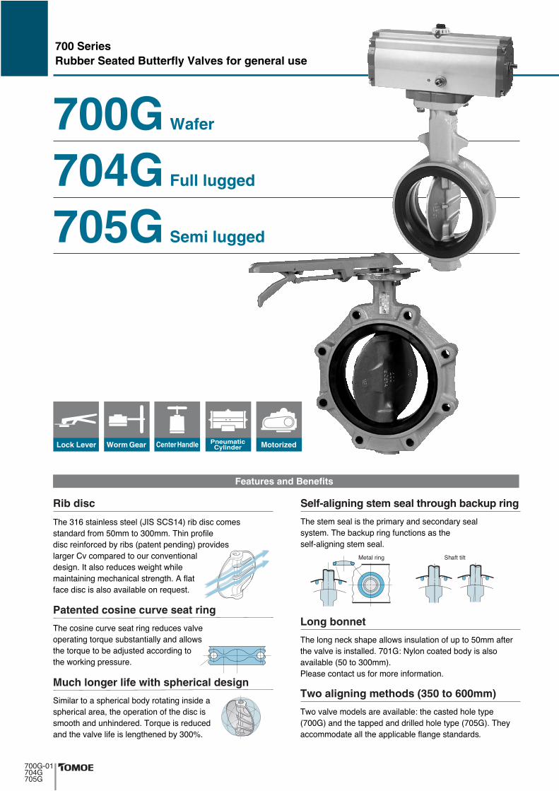
700 Series Rubber Seated Butterfly Valves for general use Rib disc Patented cosine curve seat ring Much longer life with spherical design Self-aligning stem seal through backup ring Long bonnet Two aligning methods (350 to 600mm) Features and Benefits Center Handle Lock Lever Worm Gear Pneumatic Cylinder Motorized 700G Wafer 704G Full lugged 705G Semi lugged
Transcript of 700 Series Rubber Seated Butterfly Valves for general use ... · NBR : 0 to 60 degrees C, *EPDM : 0...
700 SeriesRubber Seated Butterfly Valves for general use
��� ��� ��� ��� ��� ���� ������ ��� ���� �����
����� ���� ���� � ������ ���� ����� �
���� ���������� � ���� ���� ������!� ���"����
�!�� �" ������� � �#� ���"�����
����!�� � �� ���#��� $��!� $�� �
�������! ������� ����!�� % �
��� ���� �� �� "� � � �� ��&#���
Rib disc
��� ������ �#�"� �� ���! ���#��� " "�
������! ��&#� �#���� �� �$�
�� ��&#� � �� �'#��� �������! �
�� $��(��! �����#���
Patented cosine curve seat ring
���� � � ������� ��� ����! ������
������� ��) �� ������� �� �� ���� ��
����� �� #���������� ���&#� �� ���#���
�� �� " "� ��� �� ��!����� � ���*�
Much longer life with spherical design
��� ��� �� �� �� ����� �� ������� ��
� ���� ��� ��(#� ���! �#������ � ��
�� �+ �!���! ��� �� �
Self-aligning stem seal through backup ring
��� ��! ���( ���� �$� ���# ��� �� #� � ���� ���
�� " "� �� ��� ��� ,��-. / �� ���� ��� �� ��
"� � � ��� � �������
0 ��� ���� #� ��� ���� ����������
Long bonnet
�$� " "� ���� � �� "� � �. �� ���� �� � ��
�,��-� �� �� ���� �� ��� �� �� � �� �,��-�� ���
�������� �� �� ��� � � �!� �������
Two aligning methods (350 to 600mm)
Features and Benefits
Center HandleLock Lever Worm Gear PneumaticCylinder Motorized
��� � 1� ���!
,��-+��,��-,��-
700G Wafer
704G Full lugged
705G Semi lugged
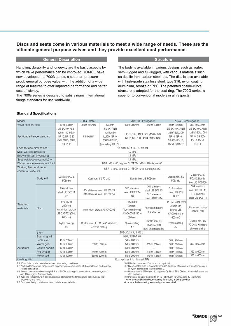
Standard Specifications
Discs and seats come in various materials to meet a wide range of needs. These are the ultimate general purpose valves and they provide excellent cost performance.
※1 16bar finish is also available subject to working conditions.※2 Working temperature range varies depending on combination of disc materials and seating. Please consult us.※3 Please consult us when using NBR and EPDM seatring continuously above 60 degrees C and 100 degrees C respectively.※4 "Working temperature in continuous use" stands for the temperature continuously kept exceeding one hour.※5 Cast steel body or stainless steel body is also available.
※6 Rib disc: standard. Flat face disc: optional.※7 Nylon coated disc is available from 40A to 300A. Maximum working temperature of nylon coated disc is 60 degrees C.※8 Heat resistant EPDM (to 150 degrees C), FPM, SEP, CR and white-NBR seats are also available.※9 Polyester powder backed finish (V-Pet #4000) for 700G size 40 to 300mm.2 /�"�� #�� � 3041 �#���� �� ���! �� �� " "� �� ����! #��� ����� �� ��� � #�� �������! �"�� � �!� ��#� �� �� �
ModelValve nominal size
Applicable flange standard
Face-to-face dimensionsMax. working pressureBody shell test (hydraulic)Seat leak test (pneumatic) ※1Working temperature range ※2,※3Working temperature incontinuous use ※4
40 to 300mmJIS 5K/10K ANSI125lb/150 lb DINNP10, NP16 BS
4504 PN10, PN16,BS 10 'E'
Ductile iron, JISFCD450
316 stainlesssteel, JIS SCS14
※6
PPS (50 to200mm)
Aluminium bronzeJIS CAC702 (50 to
600mm)
Nylon coating※7
40 to 200mm40 to 300mm40 to 300mm40 to 300mm40 to 300mm
350 to 500mm
JIS 5K/10K
Cast iron, JIS FC 250
304 stainless steel, JIS SCS13316 stainless steel, JIS SCS14
Aluminium bronze JIS CAC702
Ductile iron, JIS FCD 450 with hardchrome plating
-350 to 600mm
-350 to 600mm350 to 600mm
600mmJIS 5K, ANSI125 lb/150
lb, DIN NP10,BS4504 PN10,
(excluding JIS 10K)
Standardmaterials
Actuators
Coating ※9
Body ※5
Disc
StemSeat ring ※8Lock leverWorm gearCentre handlePneumaticMotorised
700G (Wafer) 705G (Semi lugged)704G (Fully lugged)50 to 300mm
Ductile iron, JIS FCD450
304 stainlesssteel, JIS SCS 13,
316 stainlesssteel, JIS SCS14
Aluminium bronzeJIS CAC702
Ductile iron, JISFCD 450 with
hard chrome plating
-350 to 600mm
-350 to 600mm350 to 600mm
316 stainlesssteel, JIS SCS14
※6
PPS (50 to200mm)
Aluminium bronzeJIS CAC702 (50 to
600mm)
Nylon coating※7
SUS420J2 / SUS 392 J1NBR, *EPDM ※8
50 to 200mm50 to 300mm50 to 300mm50 to 300mm50 to 300mm
Epoxy primer finish (Munsell N7)
JIS 5K/10K, ANSI 125lb/150lb, DINNP10, NP16, BS 4504 PN10/PN16
API 609 / ISO 5752 (20 series)1.0 MPa1.5 MPa1.1 MPa
NBR : -10 to 80 degrees C, *EPDM : -20 to 120 degrees C
NBR : 0 to 60 degrees C, *EPDM : 0 to 100 degrees C
350 to 600mm 50 to 300mmJIS 5K/10K, ANSI125lb/150lb, DIN
NP10, NP16,BS 4504 PN10,PN16, BS10 'E'
Ductile iron, JISFCD 450
316 stainlesssteel, JIS SCS
14 ※6
PPS (50 to 200mm)Aluminiumbronze JIS
CAC702 (50 to600mm)
Nylon coating※7
50 to 200mm50 to 300mm50 to 300mm50 to 300mm50 to 300mm
350 to 600mmJIS 5K/10K, ANSI125lb/150lb, DINNP10, BS 4504PN10, PN16,
BS10 'E'
Cast iron, JISFC250, Ductile
iron, JIS FCD450304 stainless
steel, JIS SCS 13,316 stainless
steel, JIS SCS 14
Aluminium bronzeJIS CAC702
Ductile iron, JISFCD450 with hard
chrome plating
-350 to 600mm
-350 to 600mm350 to 600mm
,��-+�5,��-,��-
6�� ��!) �#��� � �� ��!�"� �� �� ���� ����� �
$���� " "� ���������� �� �� �����"��� �7173 �"�
��$ ��"� ���� �� ,��- ������) �#������) �����#��+
�����) !���� �#����� " "�) $�� �� ������ �� $���
��!� �� ��#��� � ����� �����"�� ���������� �� ����
��� ��������� �
��� ,��- ������ �� ����!��� � ���� �� ��������
� �!� ������ ��� #�� $�� �$����
General Description
��� ��� �� "� � � �� "���#� ����!�� �#�� � $���)
����+ #!!�� �� �# + #!!��) $�� "���#� ���� � �#��
� �#�� � ����) ����� ��� ) ��� ��� ���� �� �� "� � �
$�� ��!�+!��� ��� ��� ��� ) �� ���) � �� ����!)
#����#�) ����8� �� 00�� ��� ����� ������+�#�"�
��#�#�� �� ����� ��� �� �� ���!� ��� ,��- ������ ��
�#������ � ���"����� ���� � �� ��������
Structure

8-1
8-2
8-2
9-2
9-1
9-2
9-1
11
14
1
3
g41
7
13
1617
18
610-210-1
3
33
34
30
31
32
35
1
11
11
4
14
610-2
10-1
12
2
8-1
14
6
10-2
10-1
350mm
2
12
11
700G Expanded view of components
350mm to 600mm
40mm to 300mm
SCS14
700G(Wafer)
���������������

700G Parts list
■700G Parts list(40mm to 300mm)
12346
10-110-2
111214303132333435
★ ★ ★ ★ ★ ★
BodyDiscUpper stemLower stemBottom coverHexagon boltSpring washerSecondary ringSeat ringGasketBushingO-ringO-ringSpring pinMachine screwPlate
1111122211111121
See Remark 2.
Only 50mm to 300mm
■700G Parts list(350mm to 600mm)
1 2 3 6 7
8-18-29-19-2
10-1
10-2
11 1112 1314 16 17 18
g41
★ ★ ★ ★
★
★ ★ ★
BodyDiscStemBottom coverRetainer plateTaper boltO-ringHexagon nutSpring washer
Hexagon bolt
Spring washer
Secondary ringSecondary ringSeat ringO-ringGasketBallHollow boltLock nutKey
1111124222424221111111
350mm400mm to 600mm350mm400mm to 600mm350mm400mm to 600mm
Only 400mm to 600mmOnly 400mm to 600mmOnly 400mm to 600mm
No. Description RemarksQ’ty
No. Description RemarksQ’ty
Remark 1: The ★ indicates recommended spare parts. They are supplied as “Seat ring set” with a small hexagonal spanner to remove hollow bolt.Remark 2: When the disc material is PPS, the lower stem length of types 50mm to 100mm is different from standard.
���������������

704G Expanded View of Components
704G(Full lugged)
11
80mm
3
33
34
30
31
32
35
1
11
11
4
14
610-2
10-1
12
2
8-1
8-1
8-2
8-2
9-2
9-111
14
1
3
g41
7
13
1617
18
6
10-2
10-1
2
12
9-2
9-1
11
���������������
SCS14
50mm to 300mm
50mm,65mm,80mm (JIS 5K)
14
6
10-2
10-1
350mm to 600mm
350mm

704G Parts list
■704G Parts list(50mm to 300mm)
12346
10-110-2
111214303132333435
★ ★ ★ ★ ★ ★
BodyDiscUpper stemLower stemBottom coverHexagon boltSpring washerSecondary ringSeat ringGasketBushingO-ringO-ringSpring pinMachine screwPlate
1111122211111121
See Remark 2.
■704G Parts list(350mm to 600mm)
1 2 36 7
8-18-29-19-2
10-1
10-2
11 11
12 1314 16 17 18
g41
★ ★ ★ ★
★ ★ ★ ★
BodyDiscStemBottom coverRetainer plateTaper boltO-ringHexagon nutSpring washer
Hexagon bolt
Spring washer
Secondary ringSecondary ringSeat ringO-ringGasketBallHollow boltLock nutKey
1111124222424221111111
350mm400mm to 600mm350mm400mm to 600mm350mm400mm to 600mm
Only 400mm to 600mmOnly 400mm to 600mmOnly 400mm to 600mm
No. Description RemarksQ’ty
No. Description RemarksQ’ty
Remark 1: The ★ indicates recommended spare parts. They are supplied as “Seat ring set” with a small hexagonal spanner to remove hollow bolt.Remark 2: When the disc material is PPS, the lower stem length of types 50mm to 100mm is different from standard.
���������������

8-1
8-2
9-2
9-2
9-1
9-1
11
14
1
3
g41
7
13
14
6
10-2
10-1
1617
18
610-210-1
8-1
8-2
2
12
11
705G Expanded view of components
50mm to 300mm
350mm to 600mm
350mm
SCS14
705G(Semi lugged)
���������������
3
33
34
30
31
32
35
1
11
11
4
14
610-2
10-1
12
2
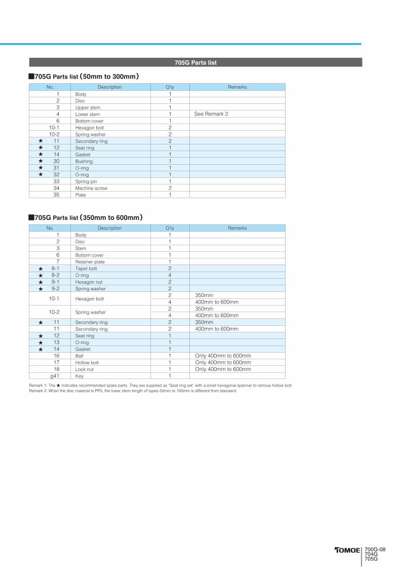
705G Parts list
■705G Parts list(50mm to 300mm)
12346
10-110-2
111214303132333435
★ ★ ★ ★ ★ ★
BodyDiscUpper stemLower stemBottom coverHexagon boltSpring washerSecondary ringSeat ringGasketBushingO-ringO-ringSpring pinMachine screwPlate
1111122211111121
See Remark 2.
■705G Parts list(350mm to 600mm)
1 2 3 6 7
8-18-29-19-2
10-1
10-2
11 1112 1314 16 17 18
g41
★ ★ ★ ★
★ ★ ★ ★
BodyDiscStemBottom coverRetainer plateTaper boltO-ringHexagon nutSpring washer
Hexagon bolt
Spring washer
Secondary ringSecondary ringSeat ringO-ringGasketBallHollow boltLock nutKey
1111124222424221111111
350mm400mm to 600mm350mm400mm to 600mm350mm400mm to 600mm
Only 400mm to 600mmOnly 400mm to 600mmOnly 400mm to 600mm
No. Description RemarksQ’ty
No. Description RemarksQ’ty
Remark 1: The ★ indicates recommended spare parts. They are supplied as “Seat ring set” with a small hexagonal spanner to remove hollow bolt.Remark 2: When the disc material is PPS, the lower stem length of types 50mm to 100mm is different from standard.
���������������

0 20 40 60 80 100 120 140 0 20 40 60 80 100-20
0.2MPa
0.4MPa
0.6MPa
0.8MPa
1.0MPa
0.2MPa
0.4MPa
0.6MPa
0.8MPa
1.0MPa
�� ���� � �� �������� �� ���� � ��� ��������
degree C (Temperature) degree C (Temperature)
(Pre
ssur
e)
(Pre
ssur
e)
700G / 704G / 705G Actuator Selection Chart
■700G
700G / 704G / 705G Pressure-Temperature Rating
Remark: For 400mm type with the accessories below, type 4I-4 should be selected. ●Micom unit ●Servo unit ●Speed control unit ●Potentiometer
Select when any of the following items apply.1Powder or high viscosity fluid (crude oil, etc.)2Control specification (with positioner)3Emergency open valve or pipe dead end valve
Select when none of the followingheavy duty items apply.
Standard
Heavy duty
Sele
ctio
n cr
iteria
50
2
40
1 1/2
65
2 1/2
80
3
100
4
125
5
150
6
200
8
250
10
300
12
350
14
400
16
450
18
500
20
600
24
ModelCate-gory
Heavy duty
Standard1T
Heavy duty
Standard2U
Heavy duty
Standard2G,2R
Heavy duty
Standard3E,3A
Heavy duty
Heavy duty
Standard3G,3F3U,3K
4 I
Standard4J,4L
ControlON-OFF
1T-1
2U-0 2U-1 2U-2 2U-3 2U-4 2U-5 2U-6
2R-42G-1
K30 K70 K170 K370 K700
4 I-0 4 I-1 4 I-2 4 I-2.5 4 I-3
SRJ-010 SRJ-020 SRJ-060LTKD-01
0.2kW/MGH-3
LTKD-01 0.4kW
/MGH-3
LTKD-050.75kW/MGH-4
1T-2 1T-3
2G-2
4 I-4
2G-3 2G-4 2R-3
TGA-160
TGA-125 TGA-140
TGA-200
TGA-180
TGA-140TGA-125
TG-12S TG-14STG-20S
TG-10S
4 I-00
K70S K170S K370SK700S
K700S
700G(Wafer)/704G(Full lugged)/705G(Semi lugged)
����)�*��������
Size mminch( (
+��'+ %',+ +��'+ %',+

45
56
69
84
104
130
153.5
199
253
302
337
394
441
492
584
80
90
115
126
146
181
211
256
322
367
410
469
525
580
682
8
8
8
10
12
14
14
18
24
24
- - - - -
70
70
70
70
70
102
102
102
102
125
140
140
140
140
165
35
43
46
46
52
56
56
60
68
78
78
102
114
127
154
61
68
79
86
103
118
135
177
215
253
276
338
368
403
458
132
138
151
156
167
191
202
227
280
312
348
383
413
453
528
21.5
21.5
21.5
22.5
22.5
27.5
27.5
30
35
35
48
54
65
79
79
Dimension (mm) Approx.Mass(kg)φd
10
10
10
12
14
16
18
22
28
32
32
40
46
50
55
φd2φD
70
70
70
70
70
102
102
102
102
125
140
140
140
140
165
□D1□S1 φC1 L H1 H2 H3
Nominal size
mm inch
40
50
65
80
100
125
150
200
250
300
350
400
450
500
600
1 1/2
2
2 1/2
3
4
5
6
8
10
12
14
16
18
20
24
1.5
1.8
2.5
2.6
3.4
5.4
7
10.4
18
25
42
64
87
114
191
700G Bare shaft (01: 40mm to 300mm, 02: 350mm to 600mm)
■Dimensions
����(����)
�� �� ����� ��� �� �����
□D1
φDφd
H1(
����� !)
H2
H3
L
φd2
"#
φ�φ$
□D1□%1
&
'#(
����� !)
'(
'�
φ$(
����)#���������

56
69
84
84
104
130
153.5
199
253
302
337
394
441
492
584
584
90
115
126
190
223
250
276
334
402483472505533
579
526634696
820
795
43
46
46
46
52
56
56
60
68
78
78
102
114
127
154
154
85
94
109
109
117
143
164
176
215
253
276
338
368
403
458
458
138
151
156
156
167
191
202
227
280
312
348
383
413
453
528
528
21.5
21.5
22.5
22.5
22.5
27.5
27.5
30
35
35
48
54
65
79
79
79
Dimension (mm) Approx.Mass(kg)φd
10
10
12
12
14
16
18
22
28
32
32
40
46
50
55
55
φd2φD
70
70
70
70
70
102
102
102
102
125
140
140
140
140
165
165
φC1 L H1 H2 H3
Nominal size
mm inch
50
65
80
80
100
125
150
200
250
300
350
400
450
500
600
600
2
2 1/2
3
3
4
5
6
8
10
12
14
16
18
20
24
24
2.5
3.5
4
4.8
6.7
8.8
10.4
16.3
27
39
66
107
128
170
275
269
8
8
10
10
12
14
14
18
24
24
- - - - - -
70
70
70
70
70
102
102
102
102
125
140
140
140
140
165
165
□D1□S1
704G Bare shaft(01: 50mm to 300mm, 02: 350mm to 600mm)
����(��������)
In Case JIS10K: *In Case JIS10K or DIN PN10: ※
*
*
*
※
※
�� �� ����� ��� �� �����
L
H3
H2
H1(Approx.)
φd2
□D1
φD
φd
□��
□��
TOMOE
φ�
φ�
�
��(�������)
��
��
φ��
704G(Full lugged)
■Dimensions
φ��
���������������

56
69
84
104
130
153.5
199
253
302
337
394
441
492
584
90
115
126
146
181
211
256
322
367
410
469
525
580
682
43
46
46
52
56
56
60
68
78
78
102
114
127
154
85
94
109
117
143
164
186
215
253
276
338
368
403
458
138
151
156
167
191
202
227
280
312
348
383
413
453
528
21.5
21.5
22.5
22.5
22.5
27.5
30
35
35
48
54
65
79
79
Dimension (mm) Approx.Mass(kg)φd
10
10
12
14
16
18
22
28
32
32
40
46
50
55
φd2φD
70
70
70
70
102
102
102
102
125
140
140
140
140
165
φC1 L H1 H2 H3
Nominal size
mm inch
50
65
80
100
125
150
200
250
300
350
400
450
500
600
2
2 1/2
3
4
5
6
8
10
12
14
16
18
20
24
2.5
3.5
4
5
8
11
15
24
31
47
72
96
127
191
705G Bare shaft(01: 50mm to 300mm, 02: 350mm to 600mm)
■Dimensions
����(�������)
�� �� ����� ��� �� �����
□D1
φDφd
L
H3
H2
H1(Approx.)
φd2
φ��
□D1 □��
φ�
φ�
�
��(�������)
��
��
φ��
8
8
10
12
14
14
18
24
24
- - - - -
70
70
70
70
102
102
102
102
125
140
140
140
140
165
□D1□S1
���������������

W
φD
L
φd
H3
H2
H1
1 T L S(standard) 1 T L R 1 T R S 1 T R R
1 T X S 1 T X R 1 T V S 1 T V R
■1T Installation direction
Lock lever type 700G-1T(40mm to 200mm)
700G(Wafer)
���������������
■700G-1T
Lever typeDimension (mm) Approx.Mass(kg)φd φD L H1 H2 H3 W
Nominal sizemm inch
40506580
100125150200
1 1/22
2 1/234568
45566984
104130153.5199
8090
115126146181211256
3543464652565660
61687986
103118135177
132138151156167191202227
66 66 66 66 66 92 92 97
200 200 200 200 200 300 300 350
1T-11T-11T-11T-11T-11T-21T-21T-3
2.1 2.4 3.1 3.2 4 6.7 8.3
12.1

45 56 69 84
104 130 153.5199 253 302 337 394 441 492 584
8090
115126146181211256322367410469525580682
3543464652565660687878
102114127154
61687986
103118135177215253276338368403458
132138151156167191202227280312348383413453528
29.529.529.529.529.534.534.541.541.548 48 50 50 50 61
36 36 36 36 36 44 44 67 67 87.587.590 90 90
113
160 160 160 160 160 173.5173.5198 198 222.5222.5266266 266 352
4646464646535375759090
105105105140
100100100100100160160200200200280280280280400
Dimension (mm) Approx.Mass(kg)φd φD L H1 H2 H3 E K F W
Gear typeNominal sizemm inch
40506580
100125150200250300350400450500600
1 1/22
2 1/234568
10121416182024
2U-02U-02U-02U-12U-12U-22U-22U-32U-32U-42U-42U-52U-52U-52U-6
3.84.14.84.95.79.6
11.218 26 39 58 80
103 130 222
Worm gear type 700G-2U(40mm to 600mm)
■700G-2U
2 U A(standard) 2 U A R 2 U B 2 U B R
■2U Installation direction
���������������
φD
H1
H2
H3
L
EK
φd
φW
F
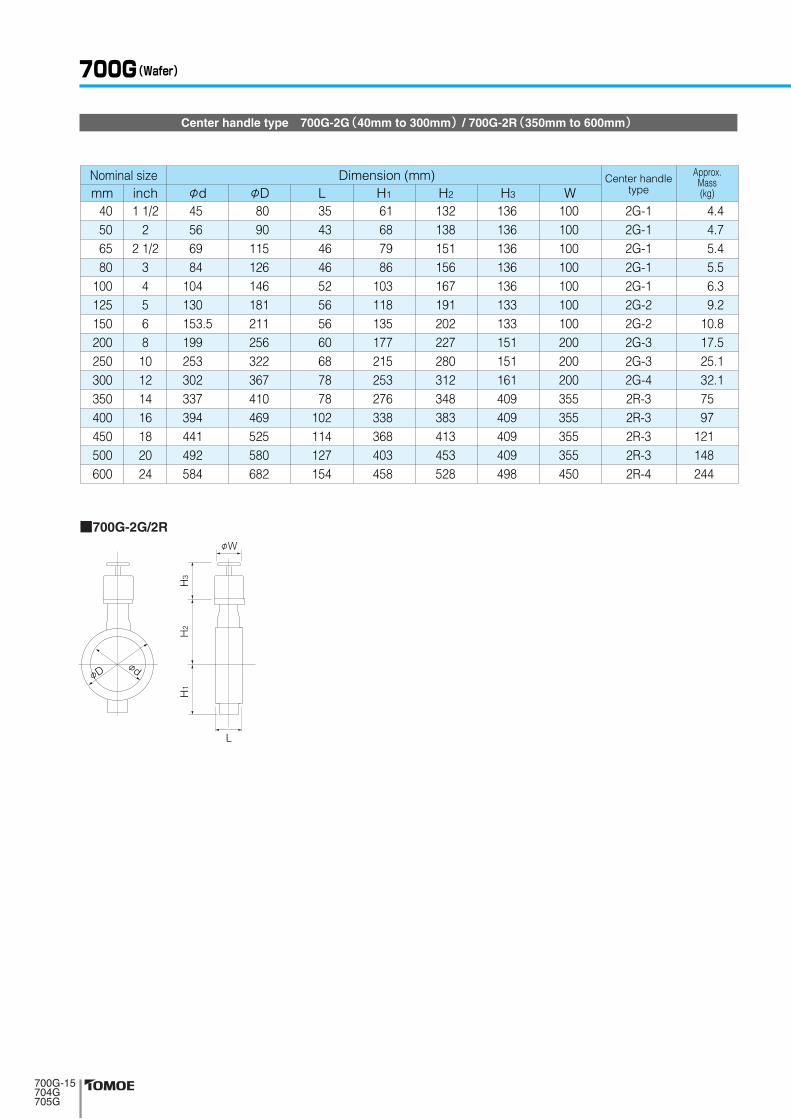
Center handle type 700G-2G(40mm to 300mm) / 700G-2R(350mm to 600mm)
700G(Wafer)
���������������
■700G-2G/2R
Dimension (mm) Approx.Mass(kg)
Center handletypeφd φD L H1 H2 H3 W
Nominal sizemm inch
40506580
100125150200250300350400450500600
1 1/22
2 1/234568
10121416182024
45566984
104130153.5199253302337394441492584
8090
115126146181211256322367410469525580682
3543464652565660687878
102114127154
61687986
103118135177215253276338368403458
132138151156167191202227280312348383413453528
136136136136136133133151151161409409409409498
100100100100100100100200200200355355355355450
2G-12G-12G-12G-12G-12G-22G-22G-32G-32G-42R-32R-32R-32R-32R-4
4.44.75.45.56.39.2
10.817.525.132.17597
121148244
φD
L
φd
φW
H1
H2
H3

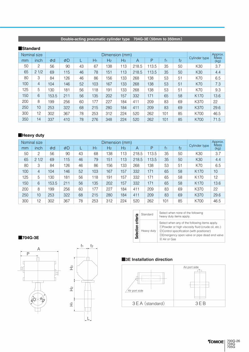
Double-acting pneumatic cylinder type 700G-3E(40mm to 350mm)
■Standard
■Heavy duty
■3E Installation direction
Select when any of the following items apply.1Powder or high viscosity fluid (crude oil, etc.)2Control specification (with positioner)3Emergency open valve or pipe dead end valve4 Air or Gas
Select when none of the followingheavy duty items apply.
Standard
Heavy duty
Sele
ctio
n cr
iteria
45 56 69 84
104 130 153.5199 253 302 337
8090
115126146181211256322367410
3543464652565660687878
61687986
103118135177215253276
132138151156167191202227280312348
113113113133133133157184184224224
218.5218.5218.5268 268 268 332 411 411 520 520
353535535353658383
101101
113.5113.5113.5138 138 138 171 209 209 262 262
5050505151515869698585
Dimension (mm) Approx.Mass(kg)φd φD L H1 H2 H3 A P f1 f2
Center handletype
Nominal sizemm inch
40506580
100125150200250300350
1 1/22
2 1/234568
101214
K30K30K30K70K70K70
K170K370K370K700K700
3.43.74.46.57.39.3
13.622 29.646.571.5
45 56 69 84
104 130 153.5199 253 302
8090
115126146181211256322367
35434646525656606878
61687986
103118135177215253
132138151156167191202227280312
113113113133157157157184184224
218.5218.5218.5268 332 332 332 411 411 520
353535536565658383
101
113.5113.5113.5138 171 171 171 209 209 262
50505051585858696985
Dimension (mm) Approx.Mass(kg)φd φD L H1 H2 H3 A P f1 f2
Center handletype
Nominal sizemm inch
40506580
100125150200250300
1 1/22
2 1/234568
1012
K30K30K30K70
K170K170K170K370K370K700
3.43.74.46.5
10 12 13.622 29.646.5
■700G-3E
L
H3
H2
H1
f1 f2A
P
φDφd
3 E A(standard) 3 E B
Air port side
Air port side
���������������

■Standard
■Heavy duty
A
P
H2
H3
H1
φD φd
f1 f2
L
3 A A(standard) 3 A B
■3A Installation direction
Double-acting pneumatic cylinder type 700G-3A(350mm to 600mm)
700G(Wafer)
743810939
1053
16418020269
100100130218
381417483543
Dimension (mm) Approx.Mass(kg)φd φD L H1 H2 H3 A P f1 f2
Cylindertype
Nominal sizemm inch400450500600
16182024
394441492584
469525580682
102114127154
338368403458
383413453528
364412465478
TGA-125TGA-140TGA-160TGA-180
101138204330
743810939939
1163
164180202202253
100100130130160
381417483483599
Dimension (mm) Approx.Mass(kg)φd φD L H1 H2 H3 A P f1 f2
Cylindertype
Nominal sizemm inch350400450500600
1416182024
337394441492584
410469525580682
78102114127154
276338368403458
348383413453528
364412465465525
TGA-125TGA-140TGA-160TGA-160TGA-200
80116188204390
Select when any of the following items apply.1Powder or high viscosity fluid (crude oil, etc.)2Control specification (with positioner)3Emergency open valve or pipe dead end valve4 Air or Gas
Select when none of the followingheavy duty items apply.
Standard
Heavy duty
Sele
ctio
n cr
iteria
���������������
■700G-3A

Single-acting pneumatic cylinder type 700G-3G(Air to open: 40mm to 250mm) / 700G-3F(Air to close: 40mm to 250mm)
■Standard
■Heavy duty
45 56 69 84
104 130 153.5199 253
8090
115126146181211256322
354346465256566068
61687986
103118135177215
132138151156167191202227280
133133157157157184184224224
362362446446446547547709709
178.5178.5220.5220.5220.5271 271 352 352
53536565658383
101101
515158585869698585
Dimension (mm) Approx.Mass(kg)φd φD L H1 H2 H3 A P f1 f2
Cylindertype
Nominal sizemm inch
40506580
100125150200250
1 1/22
2 1/234568
10
K70SK70S
K170SK170SK170SK370SK370SK700SK700S
6.66.9
11.411.512.321.222.840.347.9
45 56 69 84
104 130 153.5
8090
115126146181211
35434646525656
61687986
103118135
132138151156167191202
133133157157184184224
362362446446547547709
178.5178.5220.5220.5271 271 352
535365658383
101
51515858696985
Dimension (mm) Approx.Mass(kg)φd φD L H1 H2 H3 A P f1 f2
Cylindertype
Nominal sizemm inch
40506580
100125150
1 1/22
2 1/23456
K70SK70S
K170SK170SK370SK370SK700S
6.66.9
11.411.519.221.236.9
■700G-3G■700G-3F
AP
φDφd φD
φd
AP
H1
H2
H3
L
f1 f2
■3F Installation direction ■3G Installation direction
3 G A(standard) 3 G B3 F A(standard) 3 F B
Air port side
Air port side
Air port side
Air port side
Select when any of the following items apply.1Powder or high viscosity fluid (crude oil, etc.)2Control specification (with positioner)3Emergency open valve or pipe dead end valve4 Air or Gas
Select when none of the followingheavy duty items apply.
Standard
Heavy duty
Sele
ctio
n cr
iteria
���������������
■Standard
687878
102114127154
709494
131131164164
945108010801255125516551655
585720720865865
10951095
165206206257257348348
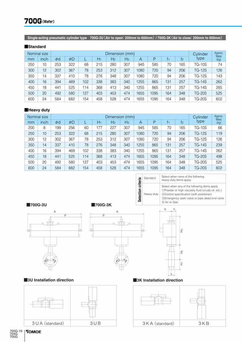
Dimension (mm) Approx.Mass(kg)φd φD L H1 H2 H3 A P f1 f2
Cylindertype
Nominal size
Dimension (mm)Nominal size
mm inch250300350400450500600
10121416182024
253302337394441492584
322367410469525580682
215253276338368403458
280312348383413453528
307307307340340474474
TG-10STG-12STG-12STG-14STG-14STG-20STG-20S
74126143262285525602
60687878
102114127154
709494
131131164164164
9451080108012551255165516551655
585720720865865
109510951095
165206206257257348348348
Approx.Mass(kg)φd φD L H1 H2 H3 A P f1 f2
Cylindertypemm inch
200250300350400450500600
810121416182024
199253302337394441492584
256322367410469525580682
177215253276338368403458
227280312348383413453528
307307307340340474474474
TG-10STG-12STG-12STG-14STG-14STG-20STG-20STG-20S
66119126239262498525602
■Heavy duty
AP
AP
φDφd φD
φd
f1f2
H1
H2
H3
L
3 K A(standard) 3 K B
■3K Installation direction
3 U A(standard) 3 U B
■3U Installation direction
Single-acting pneumatic cylinder type 700G-3U(Air to open: 200mm to 600mm) / 700G-3K(Air to close: 200mm to 600mm)
700G(Wafer)
Select when any of the following items apply.1Powder or high viscosity fluid (crude oil, etc.)2Control specification (with positioner)3Emergency open valve or pipe dead end valve4 Air or Gas
Select when none of the followingheavy duty items apply.
Standard
Heavy duty
Sele
ctio
n cr
iteria
��������������
■700G-3K■700G-3U

4 I A(standard) 4 I B
■4I Installation direction
Single phase electric motor type 700G-4 I(40mm to 500mm)
■700G-4 I
Note 1: For nominal size 40, 50 mm type (for control), the 4I-0 type should be selected. (The 4I-00 type is only designed for ON-OFF operation.)Remark: For 400mm type with the accessories below, type 4I-4 should be selected. ●Micom unit ●Servo unit ●Speed control unit ●Potentiometer
KF
φDφd
P
A
H1
H2
H3
L
45
56
6984
104130153.5199253302337
394
441492
80
90
115126146181211256322367410
469
525580
35
43
464652565660687878
102
114127
61
68
7986
103118135177215253276
338
368403
132
138
151156167191202227280312348
383
413453
120150120150150150165198198198198230230230255230230
161202161202202202252310310310310388388388388388388
588558858585
126154154154154246246246246246246
4554455454546585858585
136136136136136136
84100
84100100100138167167167167223223223223223223
Dimension (mm) Approx.Mass(kg)φd φD L H1 H2 H3 A P F K
Motortype
Nominal sizemm inch
40
50
6580
100125150200250300350
400
450500
1 1/2
2
2 1/234568
101214
16
1820
4 I-004 I-0
4 I-004 I-04 I-04 I-04 I-14 I-24 I-2
4 I-2.54 I-2.54 I-34 I-34 I-34 I-44 I-44 I-4
4 5.74.36 6.76.89.8
16.618.221.630.848.265 87 93
116 143
���������������
700G(Wafer)
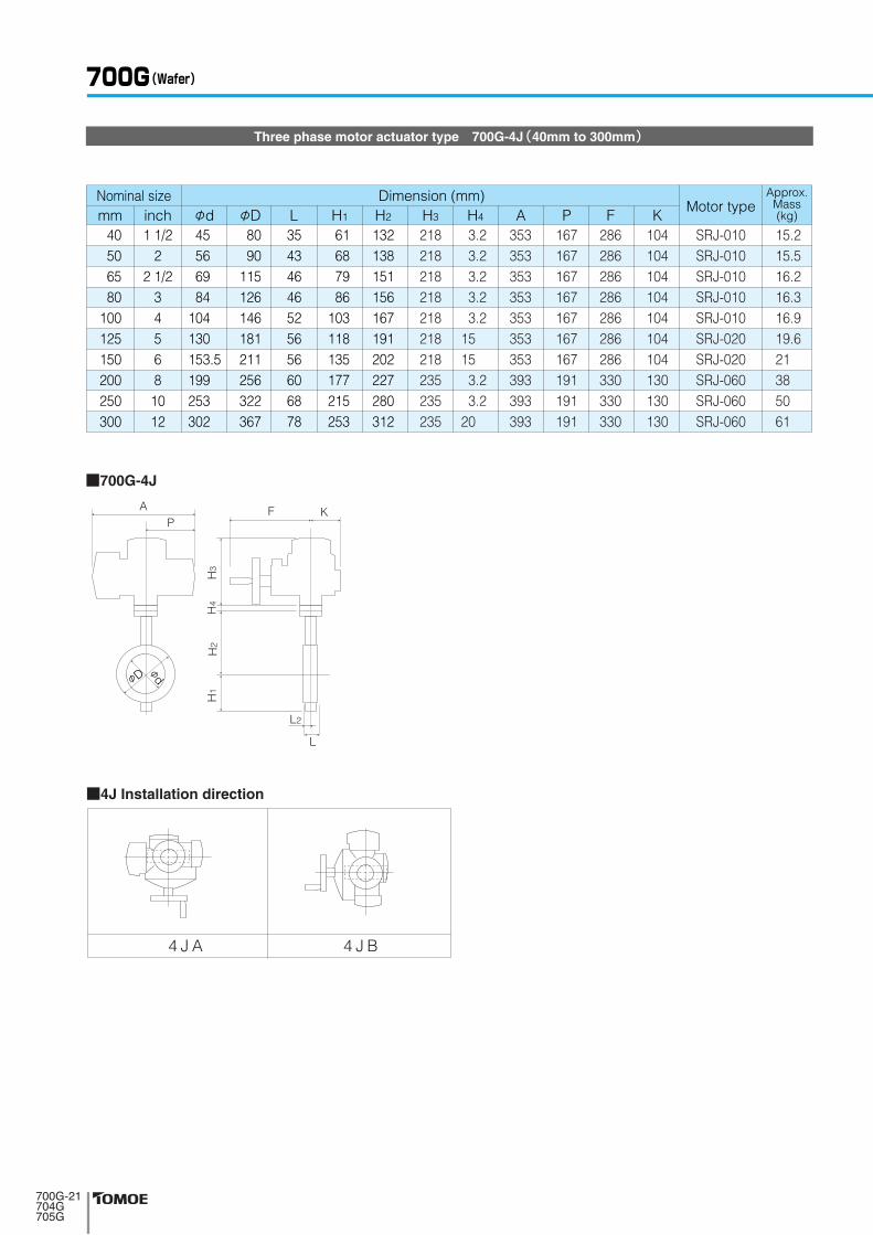
■4J Installation direction
45566984
104130153.5199253302
8090
115126146181211256322367
35434646525656606878
61687986
103118135177215253
132138151156167191202227280312
218218218218218218218235235235
353353353353353353353393393393
286286286286286286286330330330
104104104104104104104130130130
167167167167167167167191191191
Dimension (mm) Approx.Mass(kg)φd φD L H1 H2 H3
3.23.23.23.23.2
15 15
3.23.2
20
H4 A P F KMotor type
Nominal sizemm inch
40506580
100125150200250300
1 1/22
2 1/234568
1012
SRJ-010SRJ-010SRJ-010SRJ-010SRJ-010SRJ-020SRJ-020SRJ-060SRJ-060SRJ-060
15.215.516.216.316.919.621 38 50 61
4 J A 4 J B
���������������
Three phase motor actuator type 700G-4J(40mm to 300mm)
■700G-4J
FA
L
L2
KP
φD
φd
H3
H4
H2
H1
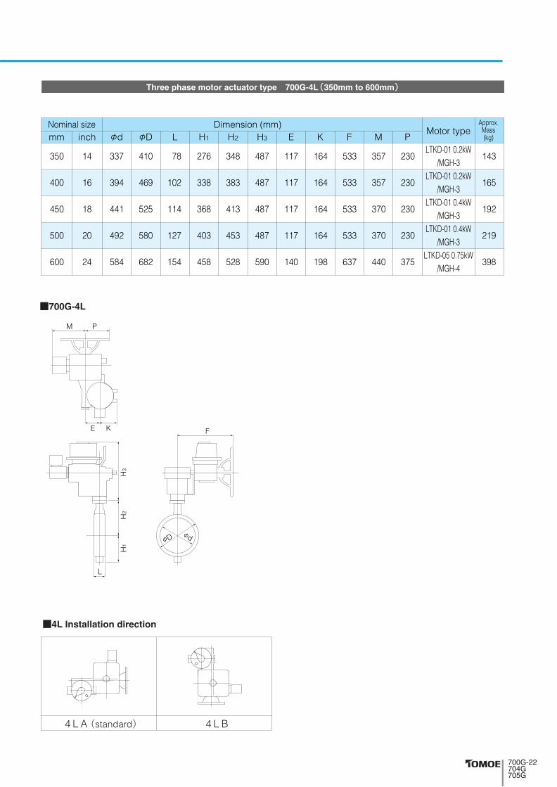
Three phase motor actuator type 700G-4L(350mm to 600mm)
Dimension (mm) Approx.Mass(kg)φd L H1 H2 H3 E K F M PφD
Nominal sizemm inch
350
400
450
500
600
14
16
18
20
24
337
394
441
492
584
410
469
525
580
682
78
102
114
127
154
276
338
368
403
458
348
383
413
453
528
487
487
487
487
590
117
117
117
117
140
164
164
164
164
198
533
533
533
533
637
357
357
370
370
440
230
230
230
230
375
LTKD-01 0.2kW/MGH-3
LTKD-01 0.2kW/MGH-3
LTKD-01 0.4kW/MGH-3
LTKD-01 0.4kW/MGH-3
LTKD-05 0.75kW/MGH-4
143
165
192
219
398
Motor type
■700G-4L
L
H3
H2
H1
φDφd
FE K
M P
4 L A(standard) 4 L B
■4L Installation direction
���������������

W
φD
L
φd
H3
H2
H1
Lock lever type 704G-1T(50mm to 200mm)
Dimension (mm)Approx.Mass
(kg)Levertypeφd L H1 H2
φDNominal size
JIS5K JIS10Kmm inch
506580
100125150200
22 1/2
34568
566984
104130153.5199
90115126223250276334
90115190223250276329
43464652565660
8594
109117143164186
138151156167191202227
66 66 66 66 92 92 97
H3 W
200 200 200 200 300 300 350
1T-11T-11T-11T-11T-21T-21T-3
3.1 4.1 4.6 (5.4) 8 11.9 15.1 22.2 (23.7)
Remark: Value in brackets is for JIS 10K flanges.
1 T L S(standard) 1 T L R 1 T R S 1 T R R
1 T X S 1 T X R 1 T V S 1 T V R
■1T Installation direction
704G(Full lugged)
■704G-1T
���������������
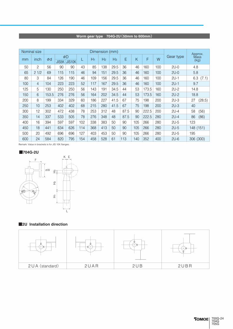
2 U A(standard) 2 U A R 2 U B 2 U B R
■2U Installation direction
■704G-2U
Worm gear type 704G-2U(50mm to 600mm)
Remark: Value in brackets is for JIS 10K flanges.
566984
104130153.5199253302337394441492584
90115126223250276334402472533597634696820
90115190223250276329402438505597626696795
43464652565660687878
102114127154
8594
109117143164186215253276338368403458
138151156167191202227280312348383413453528
29.529.529.529.534.534.541.541.5484850505061
363636364444676787.587.5909090
113
160160160160173.5173.5198198222.5222.5266266266352
46464646535375759090
105105105140
100100100100160160200200200280280280280400
Dimension (mm)Approx.
Mass(kg)φd L H1 H2 H3 E K F W
Gear typeφDNominal size
JIS5K JIS10Kmm inch
506580
100125150200250300350400450500600
22 1/2
3456810121416182024
2U-02U-02U-12U-12U-22U-22U-32U-32U-42U-42U-52U-52U-52U-6
4.85.86.39.7
14.818.827 40 58 86
123 148 195 306
(7.1)
(28.5)
(56) (86)
(151)
(300)
φD
H1
H2
H3
L
EK
φd
φW
F
���������������

Center handle type 704G-2G(50mm to 300mm) / 704G-2R(350mm to 600mm)
■704G-2G/2R
Dimension (mm) Approx.Mass(kg)φd L H1 H2
Centerhandle
typeφD
Nominal size
JIS5K JIS10Kmm inch
506580
100125150200250300350400450500600
221/2
34568
10121416182024
566984
104130153.5199253302337394441492584
90115126223250276334402472533597634696820
90115190223250276329402438505597626696795
43464652565660687878
102114127154
8594
109117143164186215253276338368403458
138151156167191202227280312348383413453528
136136136136133133151151161409409409409498
H3 W
100100100100100100200200200355355355355450
2G-12G-12G-12G-12G-22G-22G-32G-32G-42R-32R-32R-32R-32R-4
5.46.46.9
10.314.417.626.140 52
103 140 166 213 328
(7.7)
(27.6)
(50) (103)
(169)
(322) Remark: Value in brackets is for JIS 10K flanges.
704G(Full lugged)
���������������
φD
L
φd
φW
H1
H2
H3
Double-acting pneumatic cylinder type 704G-3E(50mm to 350mm)
■Heavy duty
■Standard
56 69 84
104 130 153.5199 253 302 337
90115126146181211256322367410
43464652565660687878
677886
103118135177215253276
138151156167191202227280312348
113113133133133157184184224224
218.5218.5268 268 268 332 411 411 520 520
3535535353658383
101101
113.5113.5138 138 138 171 209 209 262 262
50505151515869698585
Dimension (mm) Approx.Mass(kg)φd φD L H1 H2 H3 A P f1 f2
Cylinder typeNominal sizemm inch
506580
100125150200250300350
22 1/2
34568
101214
K30K30K70K70K70
K170K370K370K700K700
3.74.46.57.39.3
13.622 29.646.571.5
56 69 84
104 130 153.5199 253 302
90115126146181211256322367
434646525656606878
687986
103118135177215253
138151156167191202227280312
113113133157157157184184224
218.5218.5268 332 332 332 411 411 520
3535536565658383
101
113.5113.5138 171 171 171 209 209 262
505051585858696985
Dimension (mm) Approx.Mass(kg)φd φD L H1 H2 H3 A P f1 f2
Cylinder typeNominal sizemm inch
506580
100125150200250300
22 1/2
34568
1012
K30K30K70
K170K170K170K370K370K700
3.74.46.5
10 12 13.622 29.646.5
■704G-3E
L
H3
H2
H1
f1 f2A
P
φDφd
3 E A(standard) 3 E B
■3E Installation direction
Air port side
Air port side
Select when any of the following items apply.1Powder or high viscosity fluid (crude oil, etc.)2Control specification (with positioner)3Emergency open valve or pipe dead end valve4 Air or Gas
Select when none of the followingheavy duty items apply.
Standard
Heavy duty
Sele
ctio
n cr
iteria
���������������

Double-acting pneumatic cylinder type 704G-3A(350mm to 600mm)
■704G-3A
■Standard
Remark: Value in brackets is for JIS 10K flanges.
■Heavy duty
A
P
H2
H3
H1
φD φd
f1 f2
L
3 A A(standard) 3 A B
■3A Installation direction
704G(Full lugged)
Dimension (mm) Approx.Mass(kg)φd L H1 H2 H3 A P f1 f2
Cylindertype
φDNominal size
JIS5K JIS10Kmm inch
400450500600
16182024
394441492584
597634696820
597626696795
102114127154
338368403458
383413453528
364412465478
743810939
1053
381 417 483 543
100 100 130 130
164 180 202 218
TGA-125TGA-140TGA-160TGA-180
153191269414 (408)
Dimension (mm) Approx.Mass(kg)φd L H1 H2 H3 A P f1 f2
Cylindertype
φDNominal size
JIS5K JIS10Kmm inch
350400450500600
1416182024
337394441492584
533597634696820
505597626696795
78102114127154
276338368403458
348383413453528
364412465465525
743810939939
1163
381 417 483 483 599
100 100 130 130 160
164 180 202 202 253
TGA-125TGA-140TGA-160TGA-160TGA-200
109159233269474
(236)
(468)
Select when any of the following items apply.1Powder or high viscosity fluid (crude oil, etc.)2Control specification (with positioner)3Emergency open valve or pipe dead end valve4 Air or Gas
Select when none of the followingheavy duty items apply.
Standard
Heavy duty
Sele
ctio
n cr
iteria
���������������

■Standard
Single-acting pneumatic cylinder type 704G-3G(Air to open: 50mm to 250mm) / 704G-3F(Air to close: 50mm to 250mm)
■Heavy duty
56 69 84
104 130 153.5199 253
90115126146181211256322
4346465256566068
687986
103118135177215
138151156167191202227280
133157157157184184224224
362446446446547547709709
536565658383
101101
178.5220.5220.5220.5271271352352
5158585869698585
Dimension (mm) Approx.Mass(kg)φd φD L H1 H2 H3 A P f1 f2
Cylindertype
Nominal sizemm inch
506580
100125150200250
22 1/2
34568
10
K70SK170SK170SK170SK370SK370SK700SK700S
6.911.411.512.321.222.840.347.9
56 69 84
104 130 153.5
90115126146181211
434646525656
687986
103118135
138151156167191202
133157157184184224
362446446547547709
178.5220.5220.5271 271 352
5365658383
101
515858696985
Dimension (mm) Approx.Mass(kg)φd φD L H1 H2 H3 A P f1 f2
Cylindertype
Nominal sizemm inch
506580
100125150
22 1/2
3456
K70SK170SK170SS370SK370SK700S
6.911.411.519.221.236.9
■704G-3G■704G-3F
AP
φDφd φD
φd
AP
H1
H2
H3
L
f1 f2
■3F Installation direction ■3G Installation direction
3 G A(standard) 3 G B3 F A(standard) 3 F B
Air port side
Air port side
Air port side
Air port side
Select when any of the following items apply.1Powder or high viscosity fluid (crude oil, etc.)2Control specification (with positioner)3Emergency open valve or pipe dead end valve4 Air or Gas
Select when none of the followingheavy duty items apply.
Standard
Heavy duty
Sele
ctio
n cr
iteria
���������������

■704G-3U ■704G-3K
■Standard
Single-acting pneumatic cylinder type 704G-3U(Air to open: 200mm to 600mm) / 704G-3K(Air to close: 200mm to 600mm)
φd L H1 H2 H3 A P f1 f2φD
JIS5K JIS10Kmm inch
250300350400450500600
10121416182024
253302337394441492584
402472533597634696820
402438505597626696795
687878
102114127154
215253276338368403458
280312348383413453528
307307307340340474474
945108010801255125516551655
9451080108012551255165516551655
709494
131131164164
709494
131131164164164
165206206257257348348
165206206257257348348348
585720720865865
10951095
585720720865865
109510951095
TG-10STG-12STG-12STG-14STG-14STG-20STG-20S
88145171305330590686
(143)(171)
(333)
(680)
Dimension (mm) Approx.Mass(kg)φd L H1 H2 H3 A P f1 f2
Cylindertype
φDNominal size Dimension (mm)
Cylindertype
Nominal size
Approx.Mass(kg)
Dimension (mm)Cylinder
type
Nominal size
JIS5K JIS10K
■Heavy duty
mm inch
200250300350400450500600
810121416182024
199253302337394441492584
334402472533597634696820
329402438505597626696795
60687878
102114127154
186215253276338368403458
227280312348383413453528
307307307340340474474474
TG-10STG-12STG-12STG-14STG-14STG-20STG-20STG-20S
75133145267305543590686
(77)
(143)(267)
(546)
(680)Remark: Value in brackets is for JIS 10K flanges.
AP
AP
φDφd φD
φd
f1f2
H1
H2
H3
L
3 K A(standard) 3 K B
■3K Installation direction
3 U A(standard) 3 U B
■3U Installation direction
704G(Full lugged)
Select when any of the following items apply.1Powder or high viscosity fluid (crude oil, etc.)2Control specification (with positioner)3Emergency open valve or pipe dead end valve4 Air or Gas
Select when none of the followingheavy duty items apply.
Standard
Heavy duty
Sele
ctio
n cr
iteria
��������������

Single phase electric motor type 704G-4 I(50mm to 500mm)
■704G-4 I
KF
φDφd
P
A
H1
H2
H3
L
4 I A(standard) 4 I B
■4I Installation direction
Dimension (mm) Approx.Mass(kg)φd L H1 H2 H3 A P F K
Motortype
φDNominal size
JIS5K JIS10Kmm inch
50
6580
100125150200250300350
400
450500
2
2 1/234568
101214
16
18
20
56
6984
104130153.5199253302337
394
441492
90
115126223250276334402472533
597
634696
90
115190223250276329402438505
597
626696
43
464652565660687878
102
114127
85
94109117143164186215253276
338
368403
138
151156167191202227280312348
383
413453
120150150150165198198198198230230230255230230
161202202202252310310310310388388388388388388
84100100100138167167167167223223223223223223
58858585
126154154154154246246246246246246
455454546585858585
136136136136136136
4 I-004 I-04 I-04 I-04 I-14 I-24 I-2
4 I-2.54 I-2.54 I-34 I-34 I-34 I-44 I-44 I-4
5.96.77.78.2
13.821.825 30.245 68 93
130 136 161 208
(9)
(31.7)
(66)(93)
(164)
Note 1: For nominal size 50 mm type (for control), the 4I-0 type should be selected. (The 4I-00 type is only designed for ON-OFF operation.)Remark: Value in brackets is for JIS 10K flanges.Remark: For 300mm type with the accessories below, type 4I-4 should be selected. ●Micom unit ●Servo unit ●Speed control unit ●Potentiometer
���������������

Three phase motor actuator type 704G-4J(50mm to 300mm)
704G(Full lugged)
■704G-4J
Dimension (mm)Approx.
Mass(kg)φd L H1 H2 H4 A P F K
Motor typeφDNominal size
JIS5K JIS10Kmm inch
506580
100125150200250300
22 1/2
34568
1012
566984
104130153.5199253302
434646525656606878
90115190223250276329402438
90115126223250276334402472
8594
109117143164186215253
138151156167191202227280312
3.23.23.23.2
15 15
3.23.2
20
H3
218218218218218218235235235
353353353353353353393393393
286286286286286286330330330
104104104104104104130130130
167167167167167167191191191
SRJ-010SRJ-010SRJ-010SRJ-010SRJ-020SRJ-020SRJ-060SRJ-060SRJ-060
15.516.517 10.423.626.837 50 62
(17.8)
(33.5)(42)
Remark: Value in brackets is for JIS 10K flanges.■4J Installation direction
4 J A 4 J B
��������������
FA
L
L2
KP
φD
φd
H3
H4
H2
H1

Three phase motor actuator type 704G-4L(350mm to 600mm)
Dimension (mm) Approx.Mass(kg)
Motor typeφd L H1 H2 H3 E K F M PφD
Nominal size
JIS5K JIS10Kmm inch
350
400
450
500
600
14
16
18
20
24
337
394
441
492
584
533
597
634
696
820
505
597
626
696
795
78
102
114
127
154
276
338
368
403
458
348
383
413
453
528
487
487
487
487
590
117
117
117
117
140
164
164
164
164
198
533
533
533
533
637
357
357
370
370
440
230
230
230
230
375
LTKD-01 0.2kW/MGH-3
LTKD-01 0.2kW/MGH-3
LTKD-01 0.4kW/MGH-3
LTKD-01 0.4kW/MGH-3
LTKD-05 0.75kW/MGH-4
171
208
237
284
482
(171)
(240)
(476)
Remark: Value in brackets is for JIS 10K flanges.
■704G-4L
L
H3
H2
H1
φDφd
FE K
M P
4 L A(standard) 4 L B
■4L Installation direction
���������������

W
φD
L
φd
H3
H2
H1
Lock lever type 705G-1T(50mm to 200mm)
Lever typeDimension (mm) Approx.Mass
(kg)φd φD L H1 H2 H3 WNominal sizemm inch
506580
100125150200
22 1/2
34568
566984
104130153.5199
90115126146181211256
43464652565660
8594
109117143164186
138151156167191202227
66 66 66 66 92 92 97
200 200 200 200 300 300 350
1T-11T-11T-11T-11T-21T-21T-3
3.1 4.1 4.6 5.6 9.3
12.3 16.7
■705G-1T
1 T L S(standard) 1 T L R 1 T R S 1 T R R
1 T X S 1 T X R 1 T V S 1 T V R
■1T Installation direction
705G(Semi lugged)
���������������

2 U A(standard) 2 U A R 2 U B 2 U B R
■2U Installation direction
■705G-2U
Worm gear type 705G-2U(50mm to 600mm)
566984
104130153.5199253302337394441492584
90115126146181211256322367410469525580682
43464652565660687878
102114127154
8594
109117143164186215253276338368403458
138151156167191202227280312348383413453528
29.529.529.529.534.534.541.541.5484850505061
363636364444676787.587.5909090
113
160160160160173.5173.5198198222.5222.5266266266352
46464646535375759090
105105105140
100100100100160160200200200280280280280400
Dimension (mm) Approx.Mass(kg)φd φD L H1 H2 H3 E K F W
Gear typeNominal sizemm inch
506580
100125150200250300350400450500600
22 1/2
34568
10121416182024
2U-02U-02U-12U-12U-22U-22U-32U-32U-42U-42U-52U-52U-52U-6
4.85.86.37.3
12.216 23 32 45 63 88
112 143 222
φD
H1
H2
H3
L
EK
φd
φW
F
���������������

Center handle type 705G-2G(50mm to 300mm) / 705G-2R(350mm to 600mm)
■705G-2G/2R
Dimension (mm) Approx.Mass(kg)
Center handletypeφd φD L H1 H2 H3 W
Nominal sizemm inch
506580
100125150200250300350400450500600
22 1/2
34568
10121416182024
566984
104130153.5199253302337394441492584
90115126146181211256322367410469525580682
43464652565660687878
102114127154
8594
109117143164186215253276338368403458
138151156167191202227280312348383413453528
136136136136133133151151161409409409409498
100100100100100100200200200355355355355450
2G-12G-12G-12G-12G-22G-22G-32G-32G-42R-32R-32R-32R-32R-4
5.46.46.97.9
11.814.822.132 39 80
105 130 161 244
705G(Semi lugged)
���������������
φD
L
φd
φW
H1
H2
H3

Double-acting pneumatic cylinder type 705G-3E(50mm to 350mm)
■Standard
■Heavy duty
566984
104130153199253302337
90115126146181211256322367410
43464652565660687878
687986
103118135177215253276
138151156167191202227280312348
113113133133133157184184224224
218.5218.5268 268 268 332 411 411 520 520
3535535353658383
101101
113.5113.5138 138 138 171 209 209 262 262
50505151515869698585
Dimension (mm) Approx.Mass(kg)φd φD L H1 H2 H3 A P f1 f2
Cylindertype
Nominal sizemm inch
506580
100125150200250300350
22 1/2
34568
101214
K30K30K70K70K70
K170K370K370K700K700
3.74.46.57.39.3
13.622 29.646.571.5
56 69 84
104 130 153.5199 253 302
90115126146181211256322367
434646525656606878
687986
103118135177215253
138151156167191202227280312
113113133157157157184184224
218.5218.5268 332 332 332 411 411 520
3535536565658383
101
113.5113.5138 171 171 171 209 209 262
505051585858696985
Dimension (mm) Approx.Mass(kg)φd φD L H1 H2 H3 A P f1 f2
Cylindertype
Nominal sizemm inch
506580
100125150200250300
22 1/2
34568
1012
K30K30K70
K170K170K170K370K370K700
3.74.46.5
10 12 13.622 29.646.5
■705G-3E
L
H3
H2
H1
f1 f2A
P
φDφd
■3E Installation direction
3 E A(standard) 3 E B
Air port side
Air port side
Select when any of the following items apply.1Powder or high viscosity fluid (crude oil, etc.)2Control specification (with positioner)3Emergency open valve or pipe dead end valve4 Air or Gas
Select when none of the followingheavy duty items apply.
Standard
Heavy duty
Sele
ctio
n cr
iteria
���������������
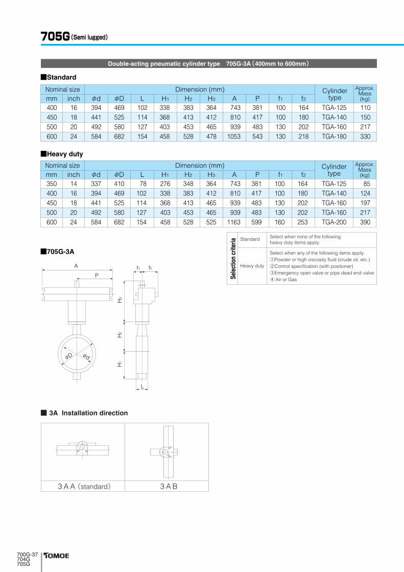
Double-acting pneumatic cylinder type 705G-3A(400mm to 600mm)
■705G-3A
■Standard
■Heavy duty
A
P
H2
H3
H1
φD φd
f1 f2
L
3 A A(standard) 3 A B
■ 3A Installation direction
705G(Semi lugged)
743810939
1053
164180202218
100100130130
381417483543
Dimension (mm) Approx.Mass(kg)φd φD L H1 H2 H3 A P f1 f2
Cylindertype
Nominal sizemm inch400450500600
16182024
394441492584
469525580682
102114127154
338368403458
383413453528
364412465478
TGA-125TGA-140TGA-160TGA-180
110150217330
743810939939
1163
164 180 202 202 253
100 100 130 130 160
381 417 483 483 599
Dimension (mm) Approx.Mass(kg)φd φD L H1 H2 H3 A P f1 f2
Cylindertype
Nominal sizemm inch350400450500600
1416182024
337394441492584
410469525580682
78102114127154
276338368403458
348383413453528
364412465465525
TGA-125TGA-140TGA-160TGA-160TGA-200
85124197217390
Select when any of the following items apply.1Powder or high viscosity fluid (crude oil, etc.)2Control specification (with positioner)3Emergency open valve or pipe dead end valve4 Air or Gas
Select when none of the followingheavy duty items apply.
Standard
Heavy duty
Sele
ctio
n cr
iteria
���������������

■Standard
Single-acting pneumatic cylinder type 705G-3G(Air to open: 50mm to 250mm) / 705G-3R(Air to close: 50mm to 250mm)
■Heavy duty
56 69 84
104 130 153.5199 253
90115126146181211256322
4346465256566068
687986
103118135177215
138151156167191202227280
133157157157184184224224
362446446446547547709709
536565658383
101101
178.5220.5220.5220.5271271352352
5158585869698585
Dimension (mm) Approx.Mass(kg)φd φD L H1 H2 H3 A P f1 f2
Cylindertype
Nominal sizemm inch
506580
100125150200250
22 1/2
34568
10
K70SK170SK170SK170SK370SK370SK700SK700S
6.911.411.512.321.222.840.347.9
56 69 84
104 130 153.5
90115126146181211
434646525656
687986
103118135
138151156167191202
133157157184184224
362446446547547709
178.5220.5220.5271 271 352
5365658383
101
515858696985
Dimension (mm) Approx.Mass(kg)φd φD L H1 H2 H3 A P f1 f2
Cylindertype
Nominal sizemm inch
506580
100125150
22 1/2
3456
K70SK170SK170SS370SK370SK700S
6.911.411.519.221.236.9
■3F Installation direction ■3G Installation direction
3 G A(standard) 3 G B3 F A(standard) 3 F B
■705G-3G■705G-3F
AP
φDφd φD
φd
AP
H1
H2
H3
L
f1 f2
Air port side
Air port side
Air port side
Air port side
Select when any of the following items apply.1Powder or high viscosity fluid (crude oil, etc.)2Control specification (with positioner)3Emergency open valve or pipe dead end valve4 Air or Gas
Select when none of the followingheavy duty items apply.
Standard
Heavy duty
Sele
ctio
n cr
iteria
���������������

■705G-3K■705G-3U
■Standard
Single-acting pneumatic cylinder type 705G-3U(Air to open: 200mm to 600mm) / 705G-3K(Air to close: 200mm to 600mm)
687878
102114127154
709494
131131164164
945108010801255125516551655
585720720865865
10951095
165206206257257348348
Dimension (mm) Approx.Mass(kg)φd φD L H1 H2 H3 A P f1 f2
Cylindertype
Nominal size
Dimension (mm) Approx.Mass(kg)
Cylindertype
Nominal size
mm inch250300350400450500600
10121416182024
253302337394441492584
322367410469525580682
215253276338368403458
280312348383413453528
307307307340340474474
TG-10STG-12STG-12STG-14STG-14STG-20STG-20S
80132148270294538602
60687878
102114127154
709494
131131164164164
9451080108012551255165516551655
585720720865865
109510951095
165206206257257348348348
φd φD L H1 H2 H3 A P f1 f2mm inch200250300350400450500600
810121416182024
199253302337394441492584
256322367410469525580682
186215253276338368403458
227280312348383413453528
307307307340340474474474
TG-10STG-12STG-12STG-14STG-14STG-20STG-20STG-20S
71125132244270507538602
■Heavy duty
AP
AP
φDφd φD
φd
f1f2
H1
H2
H3
L
3 K A(standard) 3 K B
■ 3K Installation direction
3 U A(standard) 3 U B
■ 3U Installation direction
705G(Semi lugged)
Select when any of the following items apply.1Powder or high viscosity fluid (crude oil, etc.)2Control specification (with positioner)3Emergency open valve or pipe dead end valve4 Air or Gas
Select when none of the followingheavy duty items apply.
Standard
Heavy duty
Sele
ctio
n cr
iteria
���������������

4 I A(standard) 4 I B
■ 4I Installation direction
Single phase electric motor type 705G-4 I(50mm to 500mm)
■705G-4 IKF
φDφd
PA
H1
H2
H3
L
56
6984
104130153.5199253302337
394
441492
90
115126146181211256322367410
469
525580
43
464652565660687878
102
114127
85
94109117143164186215253276
338
368403
138
151156167191202227280312348
383
413453
120150150150165198198198198230230230255230230
161202202202252310310310310388388388388388388
58858585
126154154154154246246246246246246
455454546585858585
136136136136136136
84100100100138167167167167223223223223223223
Dimension (mm) Approx.Mass(kg)φd φD L H1 H2 H3 A P F K
Motor typeNominal sizemm inch
50
6580
100125150200250300350
400
450500
2
2 1/234568
101214
16
1820
4 I-004 I-04 I-04 I-04 I-14 I-24 I-2
4 I-2.54 I-2.54 I-34 I-34 I-34 I-44 I-44 I-4
5.36.77.78.2
11.419.222.226.237 55 70 95
101 125 156
Note 1: For nominal size 50 mm type (for control), the 4I-0 type should be selected. (The 4I-00 type is only designed for ON-OFF operation.)Remark: For 400mm type with the accessories below, type 4I-4 should be selected. ●Micom unit ●Servo unit ●Speed control unit ●Potentiometer
���������������
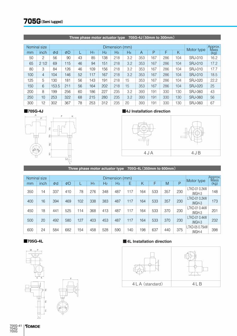
Three phase motor actuator type 705G-4J(50mm to 300mm)
Three phase motor actuator type 705G-4L(350mm to 600mm)
■705G-4L
φd L H1 H2 H3 E K F M PφDmm inch
350
400
450
500
600
14
16
18
20
24
337
394
441
492
584
410
469
525
580
682
78
102
114
127
154
276
338
368
403
458
348
383
413
453
528
487
487
487
487
590
117
117
117
117
140
164
164
164
164
198
533
533
533
533
637
357
357
370
370
440
230
230
230
230
375
LTKD-01 0.2kW/MGH-3
LTKD-01 0.2kW/MGH-3
LTKD-01 0.4kW/MGH-3
LTKD-01 0.4kW/MGH-3
LTKD-05 0.75kW/MGH-4
148
173
201
232
398
L
H3
H2
H1
φDφd
FE K
M P
4 L A(standard) 4 L B
■4L Installation direction
Dimension (mm) Approx.Mass(kg)
Motor typeNominal size
705G(Semi lugged)
■705G-4J ■4J Installation direction
56 69 84
104 130 153.5199 253 302
90115126146181211256322367
434646525656606878
8594
109117143164186215253
138151156167191202227280312
3.23.23.23.2
15 15
3.23.2
20
353353353353353353393393393
286286286286286286330330330
104104104104104104130130130
167167167167167167191191191
Dimension (mm) Approx.Mass(kg)φd φD L H1 H2 H4
218218218218218218235235235
H3 A P F KMotor type
Nominal sizemm inch
506580
100125150200250300
22 1/2
34568
1012
SRJ-010SRJ-010SRJ-010SRJ-010SRJ-020SRJ-020SRJ-060SRJ-060SRJ-060
16.217.217.718.522.225 43 56 67
4 J A 4 J B
���������������
FA
L
L2
KP
φD
φd
H3
H4
H2
H1

Valve openingNominal size
●Cv value ●Pressure loss coefficient
700G/704G/705G Cv value/pressure loss coefficient
700G/704G/705G Cv value
mm 20゚ 30゚ 40゚ 50゚ 60゚ 70゚ 80゚ 90゚ inch40506580
100125150200250300350400450500600
58
121527456067
130194232468583758
1037
915253358
109148188351487662964
120215552141
16254157
100189262347675972
13501648206826563681
25406495
162295423576
1225176420302724344843796129
3964
102163269453685969
212530113294452956927214
10106
61103162271444719
1147169833754966516768158384
1084514911
95160260450749
114418972902509174127832
10553131161710022827
121200320580880
159028004300620089009620
12700155001980027300
1 1/22
2 1/234568
10121416182024
Pre
ssur
e lo
ss c
oeffi
cien
t
Cv
valu
e
Valve opening Valve opening
���������������
(fully open)
50000
10000
5000
1000
500
100
50
10
5
20゜30゜ 40゜50゜ 60゜70゜ 80゜ 90゜
600mm500mm450mm400mm350mm300mm250mm200mm150mm125mm100mm80mm
65mm50mm40mm
(fully open)
5000
10000
1000
500
100
50
10
5
1
0.5
20゜30゜ 40゜50゜ 60゜70゜ 80゜ 90゜
40
mm
mm
mm
5065
80 to 100350 to 600
125 to 300

40506580
100125150200250300350400450500600
Valve openingNominal size
1 1/22
2 1/234568
10121416182024
700G Applicable Flange Standard
○: Can be used without flange drilling.◎: Can be used without flange drilling. (Use ANSI body.)△: With additional flange drilling. T : With flange tapping. ×: Not applicable.
BS10125Lb○ ○ ○ ◎ ◎ ◎ ○ ◎ ○ ◎ × × × × ×
150Lb○ ○ ○ ◎ ◎ ◎ ○ ◎ ○ ◎ × × × × ×
PN10○ ○ ○ ◎ ◎ ◎ ○ ◎ ○ ◎ × × × × ×
PN16○ ○ ○ ◎ ◎ ◎ ○ ◎ ○ ◎ × × × × ×
NP10○ ○ ○ ◎ ◎ ◎ ○ ◎ ○ ◎ × × × × ×
NP16○ ○ ○ ◎ ◎ ◎ ○ ◎ ○ ◎ × × × × ×
Table E○ ○ △ ○ ○ ○ ○ ○ ○ ○ × × × × ×
40506580
100125150200250300350400450500600
Nominal sizemm inch
1 1/22
2 1/234568
10121416182024
10K○ ○ ○ ○ ○ ○ ○ ○ ○ ○ ○ ○ ○ ○ T
5K○ ○ ○ ○ ○ ○ ○ ○ ○ ○ ○ ○ ○ ○ T
JIS ANSI BS4504 DIN
700G / 704G / 705G Pressure Loss Coefficient
mm 20゚ 30゚ 40゚ 50゚ 60゚ 70゚ 80゚ 90゚ inch264257310394350316348849528488531227239218247
72687583785357
10672786554565258
262528272618183120201618191820
1010111010
77
116677777
444343342232323
222111111111111
1 1 1 0.4 0.4 0.4 0.3 0.4 0.3 0.3 0.4 0.4 0.4 0.4 1
0.4 0.4 0.4 0.2 0.3 0.2 0.1 0.2 0.2 0.2 0.3 0.3 0.3 0.3 0.3
700G(Wafer)/704G(Full lugged)/705G(Semi lugged)
���������������

704G Applicable Flange Standard
○D/T: Drilled or tapped hole◎D/T: Drilled or tapped hole (JIS 5K / ANSI body used)△D/T: Drilled or tapped hole (DIN body used) ○T: Tapped hole only ◎T: Tapped hole only (JIS 5K / ANSI body used) △T: Tapped hole only (DIN body used)
D/T: Drilled or tapped hole T: Tapped hole only
BS10125Lb○D/T○D/T◎D/T○D/T○D/T○D/T◎D/T○D/T◎D/T◎D/T○D/T◎D/T○D/T◎T
150Lb○D/T○D/T◎D/T○D/T○D/T○D/T◎D/T○D/T◎D/T◎D/T○D/T◎D/T○D/T◎T
PN10○D/T○D/T○D/T○D/T○D/T○D/T◎D/T○D/T◎D/T○D/T○D/T○D/T○D/T◎T
PN16○D/T○D/T○D/T○D/T○D/T○D/T○D/T○D/T◎D/T○D/T○D/T○D/T○D/T◎T
NP10○D/T○D/T○D/T○D/T○D/T○D/T◎D/T○D/T◎D/T○D/T○D/T○D/T○D/T◎T
NP16○D/T○D/T○D/T○D/T○D/T○D/T○D/T○D/T◎D/T○D/T○D/T○D/T○D/T◎T
Table E○D/T○D/T◎D/T○D/T○D/T○D/T◎D/T○D/T◎D/T◎D/T△D/T○D/T△D/T△T
506580
100125150200250300350400450500600
mm inch2
2 1/234568
10121416182024
10K○D/T○D/T○D/T○D/T○D/T○D/T○D/T○D/T○D/T○D/T○D/T○D/T○D/T○T
5K○D/T○D/T◎D/T○D/T○D/T○D/T◎D/T○D/T◎D/T◎D/T○D/T◎D/T○D/T◎T
JIS ANSI BS4504 DINNominal size
705G Applicable Flange Standard
BS10125Lb
D/TD/TD/TD/TD/TD/TD/TD/TD/TD/TD/TD/TD/TT
150LbD/TD/TD/TD/TD/TD/TD/TD/TD/TD/TD/TD/TD/TT
PN10D/TD/TD/TD/TD/TD/TD/TD/TD/TD/TD/TD/TD/TT
PN16D/TD/TD/TD/TD/TD/TD/TD/TD/TD/TD/TD/TD/TT
NP10D/TD/TD/TD/TD/TD/TD/TD/TD/TD/TD/TD/TD/TT
NP16D/TD/TD/TD/TD/TD/TD/TD/TD/TD/TD/TD/TD/TT
Table ED/TD/TD/TD/TD/TD/TD/TD/TD/TD/TD/TD/TD/TT
506580
100125150200250300350400450500600
mm inch2
2 1/234568
10121416182024
10KD/TD/TD/TD/TD/TD/TD/TD/TD/TD/TD/TD/TD/TT
5KD/TD/TD/TD/TD/TD/TD/TD/TD/TD/TD/TD/TD/TT
JIS ANSI BS4504 DINNominal size
���������������
700G(Wafer)/704G(Full lugged)/705G(Semi lugged)
Nominal size
40
50
65
80
100
125
150
200
250
300
350
400
450
500
600
1 1/2
2
2 1/2
3
4
5
6
8
10
12
14
16
18
20
24
○
○
○
○
○
○
○
○
○
○
○
○
○
○
-
mm inch-
-
-
-
-
-
-
-
-
-
○
○
○
○
○
-
○
○
○
○
○
○
○
○
○
○
○
○
○
○
○
○
○
○
○
○
○
○
○
○
○
○
○
○
○
○
○
○
○
○
○
○
○
○
○
○
-
-
-
-
○
○
○
○
○
○
○
○
○
○
-
-
-
-
-
○
○
○
○
○
○
○
○
○
○
-
-
-
-
-
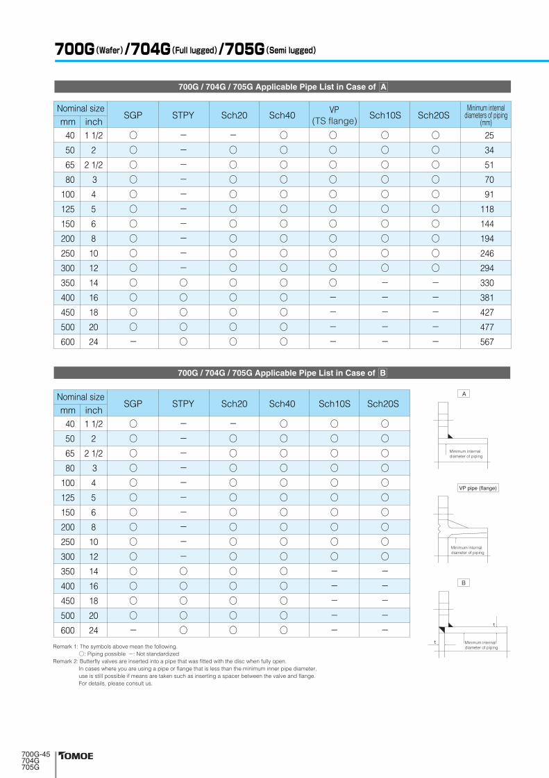
25
34
51
70
91
118
144
194
246
294
330
381
427
477
567
Minimum internaldiameters of piping
(mm)Sch20 Sch40 Sch10S Sch20S
Nominal size
40
50
65
80
100
125
150
200
250
300
350
400
450
500
600
1 1/2
2
2 1/2
3
4
5
6
8
10
12
14
16
18
20
24
○
○
○
○
○
○
○
○
○
○
○
○
○
○
-
mm inch-
-
-
-
-
-
-
-
-
-
○
○
○
○
○
-
○
○
○
○
○
○
○
○
○
○
○
○
○
○
○
○
○
○
○
○
○
○
○
○
○
○
○
○
○
○
○
○
○
○
○
○
○
○
○
-
-
-
-
-
○
○
○
○
○
○
○
○
○
○
-
-
-
-
-
Sch20 Sch40 Sch10S Sch20S
Remark 1: The symbols above mean the following.○: Piping possible -: Not standardized
Remark 2: Butterfly valves are inserted into a pipe that was fitted with the disc when fully open.In cases where you are using a pipe or flange that is less than the minimum inner pipe diameter, use is still possible if means are taken such as inserting a spacer between the valve and flange.For details, please consult us.
700G / 704G / 705G Applicable Pipe List in Case of B
700G / 704G / 705G Applicable Pipe List in Case of A
Minimum internaldiameter of piping
A
Minimum internaldiameter of piping
�� ���� �����
Minimum internaldiameter of piping
t
t
B
(TS flange)
���������������

■For Hexagon Bolts and Nuts
700G Piping Bolts and Nuts Sizes
mm inch40506580
100125150200250300350400450500600
1 1/22
2 1/234568
10121416182024
JIS 5K JIS 10K
4-M12× 75×304-M12× 90×304-M12× 90×304-M16× 95×388-M16×105×388-M16×110×388-M16×115×388-M20×130×5212-M20×140×5212-M20×150×5212-M22×155×4516-M22×180×4516-M22×190×4520-M22×205×4516-M24×235×50
— — — — — — — — — — — — — —
8-M24× 70×54
4-M16× 90×384-M16×100×384-M16×105×388-M16×105×388-M16×110×388-M20×125×468-M20×130×5212-M20×130×5212-M22×150×6016-M22×160×6016-M22×160×4516-M24×190×4520-M24×205×4520-M24×215×4520-M30×255×60
— — — — — — — — — — — — — —
8-M30× 75×60
Setting Bolts Setting Bolts
■For Long Bolts and Nuts
mm inch40506580
100125150200250300350400450500600
1 1/22
2 1/234568
10121416182024
JIS 5K JIS 10K ANSI 125Lb/150Lb
4-M12× 95×254-M12×105×254-M12×110×254-M16×120×308-M16×130×308-M16×130×308-M16×140×358-M20×155×40
12-M20×165×4012-M20×175×4012-M22×185×4516-M22×205×4516-M22×225×4520-M22×230×4516-M24×275×50
Setting Bolts
— — — — — — — — — — — — — —
8-M24× 70×54
— — — — — — — — — — — — — —
8-M30× 75×60
Setting Bolts Setting Bolts
— — — — — — — — — — — — — —
8-U1 1/4×95×70
4-M16×110×254-M16×120×304-M16×125×308-M16×125×308-M16×130×308-M20×150×408-M20×155×40
12-M20×165×4012-M22×175×4516-M22×185×4516-M22×185×4516-M24×220×5020-M24×245×5020-M24×265×5020-M30×300×60
4-U1/2 ×110×32 4-U5/8 ×140×38 4-U5/8 ×140×38 4-U5/8 ×140×38 8-U5/8 ×150×38 8-U3/4 ×160×51 8-U3/4 ×165×51 8-U3/4 ×175×51 12-U7/8 ×195×58 12-U7/8 ×205×58 12-U1 ×225 16-U1 ×255 16-U1 1/8 ×280 20-U1 1/8 ×295 16-U1 1/4 ×340
M
S S
L
L
M
S
Remarks:1. Please use a hexagon nut with 80% threading. (For ANSI, use heavy nut.)2. A unified screw should have 8 threads per inch if its nominal diameter exceeds 1 inch.* Nominal size “600 mm” requires hexagon bolt for setting.
Long bolts: 12 - M22 × 185 × 45
Quantity Nominal size (M) Length of bolt (L) Effective screw length (S)
Example
Setting bolts: 4 - M30 × 95 × 65
Quantity Nominal size (M) Length of bolt (L) Effective screw length (S)
(Hexagon bolts)
Long bolts and nuts
Setting bolts (Hexagon bolts) Setting bolt holes
Setting bolt holes
Nominal size
Nominal size
���������������
Hexagon Bolts and Nuts Hexagon Bolts and Nuts
Long Bolts and Nuts Long Bolts and Nuts Long Bolts and Nuts

700G(Wafer)/704G(Full lugged)/705G(Semi lugged)
704G Piping Bolts and Nuts Sizes
mm inch506580
100125150200250300350400450500600
22 1/2
34568
10121416182024
JIS 10K ANSI 125Lb ANSI 150LbDIN NP10
BS 4504 PN10JIS 5K
8-M12×30×28 8-M12×35×33 8-M16×35×3316-M16×40×3816-M16×40×3816-M16×40×3816-M20×45×4124-M20×50×4624-M20×55×5124-M22×60×5032-M22×60×5032-M22×60×5040-M22×60×5040-M24×70×50
8-M16×35×33 8-M16×35×3316-M16×35×3316-M16×40×3816-M20×45×4116-M20×45×4124-M20×50×4624-M22×50×4632-M22×55×5132-M22×60×5032-M24×70×5040-M24×70×5040-M24×70×5048-M30×75×60
8-M16×35×33 8-M16×35×3316-M16×40×3816-M16×40×3816-M16×40×3816-M20×45×4116-M20×50×4624-M20×55×5024-M20×55×5032-M20×60×4632-M24×70×5040-M24×70×5040-M24×70×5040-M27×80×60
8-U 5/8×35×30 8-U 5/8×40×30 8-U 5/8×40×3816-U 5/8×45×3816-U 3/4×50×4416-U 3/4×50×4416-U 3/4×55×4424-U 7/8×60×5024-U 7/8×60×5024-U1 ×70×5732-U1 ×75×5732-U1・1/8×85×6340-U1・1/8×85×6340-U1・1/4×95×70
8-5/8-11UNC×38 8-5/8-11UNC×40 8-5/8-11UNC×4516-5/8-11UNC×4516-3/4-10UNC×5016-3/4-10UNC×5016-3/4-10UNC×5524-7/8- 9UNC×6024-7/8- 9UNC×6024-1- 8UNC×7032-1- 8UNC×7032-1・1/8-8UN ×8040-1・1/8-8UN ×8040-1・1/4-8UN ×90
M
S S
L
L
M
S
* Dimensions on the table show when the piping flange hole are tapped. For drilled holes, please consult us.
Remarks:1. The bolt lengths are in accordance with thickness of steel flanges.2. A unified screw should have 8 threads per inch if its nominal diameter exceeds 1 inch.3. The list is exclusively for standard material “SS400”.
Long bolts: 12 - M22 × 185 × 45
Quantity Nominal size (M) Length of bolt (L) Effective screw length (S)
Example
Setting bolts: 4 - M30 × 95 × 65
Quantity Nominal size (M) Length of bolt (L) Effective screw length (S)
(Hexagon bolts)
Long bolts and nuts
Setting bolts (Hexagon bolts) Setting bolt holes
Setting bolt holes
���������������
Nominal size

■For Long Bolts and Nuts (Flange Bolt Hole: Tapped Holes)
705G Piping Bolts and Nuts Sizes
mm inch50
65
80
100125150200250300350400450500600
2
2 1/2
3
4568
10121416182024
JIS10K JIS5K Setting Bolts
ANSI125Lb/150Lb
—
—
—
4-M16×130×30 4-M16×130×30 4-M16×140×35 4-M20×155×40 8-M20×165×40 8-M20×175×40 8-M22×185×45
12-M22×205×45 12-M22×225×45 16-M22×230×45 16-M24×275×50
—
—
—
4-U5/8-11UNC×165×50 4-U3/4-10UNC×175×55 4-U3/4-10UNC×175×55 4-U3/4-10UNC×175×55 8-U7/8- 9UNC×215×55 8-U7/8- 9UNC×215×55
8-U1 - 8UNC×225 12-U1 - 8UNC×255
12-U1 1/8- 8UN×280 16-U1 1/8- 8UN×295 16-U1 1/4- 8UN×340
—
—
4-M16×125×30
4-M16×130×30 4-M20×150×40 4-M20×155×40 8-M20×155×40 8-M22×175×45
12-M22×185×45 12-M22×185×45 12-M24×220×50 16-M24×230×50 16-M24×245×50 20-M30×290×60
Setting BoltsSetting Bolts
8-U5/8-11UNC×35×30 8-U5/8-11UNC×40×30
(8-U5/8-11UNC×35×30)8-U5/8-11UNC×45×38
(8-U5/8-11UNC×40×30)8-U5/8-11UNC×45×38 8-U3/4-10UNC×50×44 8-U3/4-10UNC×50×44 8-U3/4-10UNC×55×44 8-U7/8- 9UNC×60×50 8-U7/8- 9UNC×60×50 8-U1 - 8UNC×70×57 8-U1 - 8UNC×75×57 8-U1 1/8-8UN×85×63 8-U1 1/8-8UN×85×63 8-U1 1/4-8UN×95×70
8-M12× 30×28
8-M12× 35×33
8-M16× 35×33
8-M16× 40×38 8-M16× 40×38 8-M16× 40×38 8-M20× 45×41 8-M20× 50×46 8-M20× 55×51 8-M22× 60×50 8-M22× 60×50 8-M22× 60×50 8-M22× 60×50 8-M24× 70×54
8-M16× 35×33
8-M16× 35×33
8-M16× 35×33
8-M16× 40×38 8-M20× 45×41 8-M20× 45×41 8-M20× 50×46 8-M22× 55×50 8-M22× 60×55 8-M22× 60×50 8-M24× 70×50 8-M24× 70×50 8-M24× 70×50 8-M30× 70×60
■For Hexagon Bolts and Nuts (Flange Bolt Hole: Tapped Holes)
mm inch50 65 80
100 125 150 200 250 300 350 400 450 500 600
22 1/2
34568
10121416182024
JIS 5K JIS 10K
— — —
4-M16×110×40 4-M16×110×40 4-M16×120×40 4-M20×130×50 8-M20×135×50 8-M20×150×50 8-M22×160×60
12-M22×175×45 12-M22×185×45 16-M22×205×45 16-M24×230×50
— —
4-M16×110×40 4-M16×110×40 4-M20×120×50 4-M20×130×50 8-M20×135×50 8-M22×150×60
12-M22×160×60 12-M22×160×40 12-M24×190×45 16-M24×205×45 16-M24×215×45 20-M30×255×50
8-M16× 35×32 8-M16× 35×32 8-M16× 35×32 8-M16× 40×38 8-M20× 45×41 8-M20× 45×41 8-M20× 50×46 8-M22× 55×50 8-M22× 60×55 8-M22× 60×50 8-M24× 70×50 8-M24× 70×50 8-M24× 70×50 8-M30× 70×60
8-M12× 30×28 8-M12× 35×33 8-M16× 35×33 8-M16× 40×38 8-M16× 40×38 8-M16× 40×38 8-M20× 45×41 8-M20× 50×46 8-M20× 55×51 8-M22× 60×50 8-M22× 60×50 8-M22× 60×50 8-M22× 60×50 8-M24× 70×54
Setting Bolts Setting Bolts
M
S S
L
L
M
S
Hexagon Bolts and NutsHexagon Bolts and Nuts
Long Bolts and Nuts Long Bolts and Nuts Long Bolts and Nuts
Remarks:Bolt/Nut material: SS400/SS400, SUS304/SUS304The dimensions in parenthesis show ANSI125Lb. (for 65 mm and 80 mm)Heavy nut shall be used for ANSI125Lb/150Lb hexagon nuts.A unified screw should have 8 threads per inch if its nominal diameter exceeds 1 inch.
Long bolts and nuts
Setting bolts (Hexagon bolts)Setting bolt holes
Setting bolt holes
Long bolts: 12 - M22 × 185 × 45
Quantity Nominal size (M) Length of bolt (L) Effective screw length (S)
Example
Setting bolts: 4 - M30 × 95 × 65
Quantity Nominal size (M) Length of bolt (L) Effective screw length (S)
(Hexagon bolts)
���������������
Nominal size
Nominal size


![Ordinance No. 19-92 Attachment - Zanesville, Ohio...2019/08/12 · o degrees [d] 30 degrees 45 degrees 60 degrees 90 degrees [e] Dnveway width [f] m feet: Residential Districts Minimum](https://static.fdocuments.in/doc/165x107/5f40e8cf15dd5c29445849f0/ordinance-no-19-92-attachment-zanesville-20190812-o-degrees-d-30.jpg)