7€¦ · Web viewAbdominal penetration / Dummy criteria frontal and rear impact. 7.1.4.3.1. ......
52
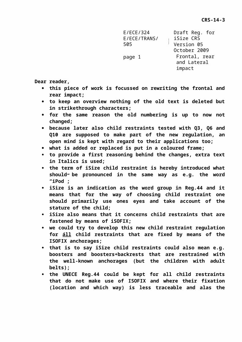
CRS-14-3 E/ECE/324 E/ECE/TRANS/ 505 Draft Reg. for iSize CRS Version 05 October 2009 page 1 Frontal, rear and Lateral impact Dear reader, this piece of work is focussed on rewriting the frontal and rear impact; to keep an overview nothing of the old text is deleted but in strikethrough characters; for the same reason the old numbering is up to now not changed; because later also child restraints tested with Q3, Q6 and Q10 are supposed to make part of the new regulation, an open mind is kept with regard to their applications too; what is added or replaced is put in a coloured frame; to provide a first reasoning behind the changes, extra text in Italics is used; the term of iSize child restraint is hereby introduced what should be pronounced in the same way as e.g. the word “iPod”; iSize is an indication as the word group in Reg.44 and it means that for the way of choosing child restraint one should primarily use ones eyes and take account of the stature of the child; iSize also means that it concerns child restraints that are fastened by means of iSOFIX; we could try to develop this new child restraint regulation for áll child restraints that are fixed by means of the ISOFIX anchorages; that is to say iSize child restraints could also mean e.g. boosters and boosters+backrests that are restrained with the well-known anchorages (but the children with adult belts); the UNECE Reg.44 could be kept for all child restraints that do not make use of ISOFIX and where their fixation (location and which way) is less traceable and alas the
Transcript of 7€¦ · Web viewAbdominal penetration / Dummy criteria frontal and rear impact. 7.1.4.3.1. ......
CRS-14-3
E/ECE/324E/ECE/TRANS/505
Draft Reg. for iSize CRSVersion 05 October 2009
page 1 Frontal, rear and Lateral impact
Dear reader, this piece of work is focussed on rewriting the frontal and rear impact; to keep an overview nothing of the old text is deleted but in strikethrough
characters; for the same reason the old numbering is up to now not changed; because later also child restraints tested with Q3, Q6 and Q10 are supposed to make
part of the new regulation, an open mind is kept with regard to their applications too;
what is added or replaced is put in a coloured frame; to provide a first reasoning behind the changes, extra text in Italics is used; the term of iSize child restraint is hereby introduced what should be pronounced in
the same way as e.g. the word “iPod”; iSize is an indication as the word group in Reg.44 and it means that for the way of
choosing child restraint one should primarily use ones eyes and take account of the stature of the child;
iSize also means that it concerns child restraints that are fastened by means of iSOFIX;
we could try to develop this new child restraint regulation for áll child restraints that are fixed by means of the ISOFIX anchorages;
that is to say iSize child restraints could also mean e.g. boosters and boosters+backrests that are restrained with the well-known anchorages (but the children with adult belts);
the UNECE Reg.44 could be kept for all child restraints that do not make use of ISOFIX and where their fixation (location and which way) is less traceable and alas the outcome of accidents too!
Hans Ammerlaan - NL MOT/RDW
Dear Reader Clepa contributions for frontal, rear and side impacts are highlighted in blue colour and in italic characters. Clepa contribution focuses on Phase 1 of the new regulation, therefore most of requirements or definitions related to belted CRSs were deleted. Therefore we concentrate here on Isofix Integral Universal products.
7. PARTICULAR SPECIFICATIONS
7.1. Provisions applicable to the assembled restraint
Remark: 7.1.1. -7.1.3 concern resistance to corrosion, energy absorption and overturning and are not taken on board in this piece of work.

CRS-14-3
E/ECE/324E/ECE/TRANS/505
Draft Reg. for iSize CRSVersion 05 October 2009
page 2 Frontal, rear and Lateral impact
7.1.4. Dynamic test s
7.1.4.1. General. The child restraint shall be subjected to a dynamic tests in conformity with paragraph 8.1.3. below.
Remark: paragraph 8.1.3. must be extended with “Description of the side impact test” and this paragraph 7 must be extended with the particular specifications of the side impact test.Remark: NPACS test bench is defined for all dynamic tests, rear, front and lateral dynamic
test, including differences of Isofix anchorage attachment to the bench for frontal and side impact.
7.1.4.1.1. Child restraints of the "universal" , "restricted" and "semi-universal" categories category shall be tested on the test trolley by means of the test seat prescribed in paragraph 6., and in conformity with paragraph 8.1.3.1.
Remark : As we are dealing with Universal category, the tests with vehicles or with body in white should not be considered here. Suggest putting corresponding parts of 7 1 4 1 2 in brackets.
[7.1.4.1.2. Child restraints of the "specific vehicle" category shall be tested with each vehicle model for which the child restraint is intended. The Technical Service responsible for conducting the test may reduce the number of vehicle models tested if they do not differ greatly in the aspects listed in paragraph 7.1.4.1.2.3. The child restraint may be tested in one of the following ways:
7.1.4.1.2.1. On a complete vehicle, as prescribed in paragraph 8.1.3.3.;
7.1.4.1.2.2. In a vehicle body shell on the test trolley, as prescribed in paragraph 8.1.3.2.; or,
7.1.4.1.2.3. In sufficient parts of the vehicle bodyshell to be representative of the vehicle structure and impact surfaces. If the child restraint is intended for use in the rear seat, these shall include the back of the front seat, the rear seat, the floor pan, the B and C pillars and the roof. If the child restraint is intended for use in the front seat, the parts shall include the dashboard, the A pillars, the windscreen, any levers or knobs installed in the floor or on a console, the front seat, the floor pan and the roof. Furthermore, if the child restraint is intended for use in combination with the adult safety belt, the parts shall include the appropriate adult belt(s). The Technical Service responsible for conducting the test may permit items to be excluded if they are found to be superfluous. Testing shall be as prescribed in paragraph 8.1.3.2. ]
7.1.4.1.3. The dynamic test shall be performed on child restraints which have not previously been under load.

CRS-14-3
E/ECE/324E/ECE/TRANS/505
Draft Reg. for iSize CRSVersion 05 October 2009
page 3 Frontal, rear and Lateral impact
7.1.4.1.4. During the dynamic tests, no part of the child restraint actually helping to keep the child in position shall break, and no buckles or locking system or displacement system shall release.
Remark: must be placed in the part with criteria of the dynamic test!!
7.1.4.1.5. In the case of "non-integral type" the seat belt used shall be the standard belt and its anchorage brackets prescribed in Annex 13 to this Regulation. This does not apply to "specific vehicle" approvals where the actual belt of the vehicle shall be used.
Remark: Here we are dealing with Phase 1 of the new regulation. So belted child restraint systems are not covered.
Remark: because iSize child restraints could also mean boosters for heavier children where only the CRS is held by the ISOFIX anchorages and the child by the adult belt, this paragraph must return in some way.
7.1.4.1.6. If a "specific vehicle" child restraint system is installed in the area behind the rearmost forward facing adult seat positions (for example, the luggage area), one test with the largest dummy/dummies on a complete vehicle as prescribed in paragraph 8.1.3.3.3. shall be performed. The other tests, including the conformity of production, may be done as prescribed in paragraph 8.1.3.2., if the manufacturer so wishes.
7.1.4.1.7. In the case of a "Special Needs Restraint" every dynamic test specified by this Regulation for each mass group shall be performed twice: first, using the primary means of restraint and second, with all restraining devices in use. In these tests, special attention shall be given to the requirements in paragraphs 6.2.3. and 6.2.4.
7.1.4.1.8. During the dynamic tests, the standard safety-belt used to install the child restraint shall not become disengaged from any guide or locking device utilised for the test conducted.
Remark: this paragraph must return is some way in the part with criteria of the dynamic test, because iSize child restraints could also mean boosters (with backrests!) for heavier children where the CRS is “held” by the ISOFIX anchorages but where the diagonal part of the adult belt receives some guidance from the backrest for an improved fitting of the child.
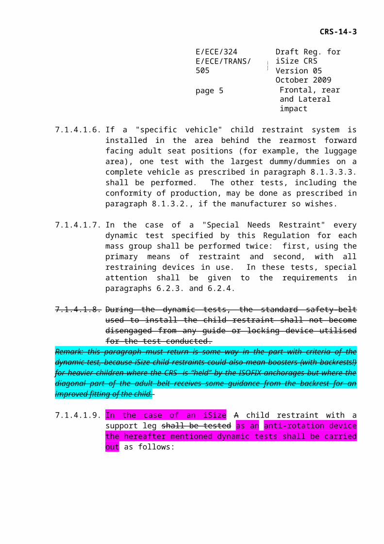
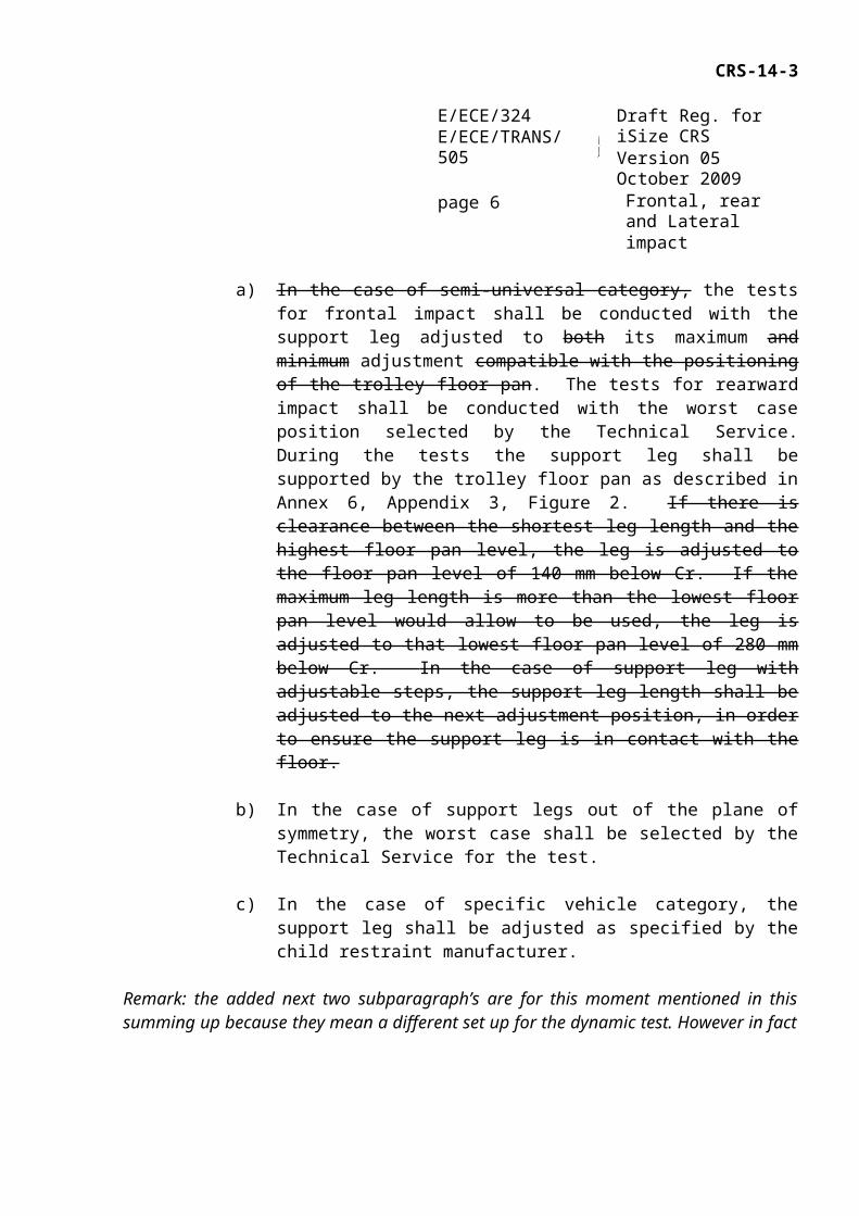
7.1.4.1.9. In the case of an iSize A child restraint with a support leg shall be tested as an anti-rotation device the hereafter mentioned dynamic tests shall be carried out as follows:
a) In the case of semi-universal category, the tests for frontal impact shall be conducted with the support leg adjusted to both its maximum and minimum adjustment compatible with the positioning of the trolley floor

CRS-14-3
E/ECE/324E/ECE/TRANS/505
Draft Reg. for iSize CRSVersion 05 October 2009
page 4 Frontal, rear and Lateral impact
pan. The tests for rearward impact shall be conducted with the worst case position selected by the Technical Service. During the tests the support leg shall be supported by the trolley floor pan as described in Annex 6, Appendix 3, Figure 2. If there is clearance between the shortest leg length and the highest floor pan level, the leg is adjusted to the floor pan level of 140 mm below Cr. If the maximum leg length is more than the lowest floor pan level would allow to be used, the leg is adjusted to that lowest floor pan level of 280 mm below Cr. In the case of support leg with adjustable steps, the support leg length shall be adjusted to the next adjustment position, in order to ensure the support leg is in contact with the floor.
b) In the case of support legs out of the plane of symmetry, the worst case shall be selected by the Technical Service for the test.
c) In the case of specific vehicle category, the support leg shall be adjusted as specified by the child restraint manufacturer.
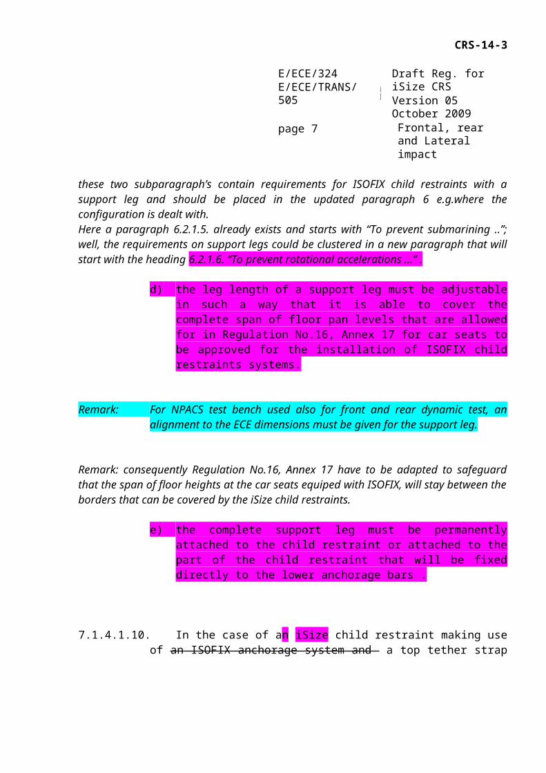
Remark: the added next two subparagraph’s are for this moment mentioned in this summing up because they mean a different set up for the dynamic test. However in fact these two subparagraph’s contain requirements for ISOFIX child restraints with a support leg and should be placed in the updated paragraph 6 e.g.where the configuration is dealt with.Here a paragraph 6.2.1.5. already exists and starts with “To prevent submarining ..”; well, the requirements on support legs could be clustered in a new paragraph that will start with the heading 6.2.1.6. “To prevent rotational accelerations …” .
d) the leg length of a support leg must be adjustable in such a way that it is able to cover the complete span of floor pan levels that are allowed for in Regulation No.16, Annex 17 for car seats to be approved for the installation of ISOFIX child restraints systems.
Remark: For NPACS test bench used also for front and rear dynamic test, an alignment to the ECE dimensions must be given for the support leg.
Remark: consequently Regulation No.16, Annex 17 have to be adapted to safeguard that the span of floor heights at the car seats equiped with ISOFIX, will stay between the borders that can be covered by the iSize child restraints.
e) the complete support leg must be permanently attached to the child restraint or attached to the part of the child restraint that will be fixed directly to the lower anchorage bars .
CRS-14-3
E/ECE/324E/ECE/TRANS/505
Draft Reg. for iSize CRSVersion 05 October 2009
page 5 Frontal, rear and Lateral impact
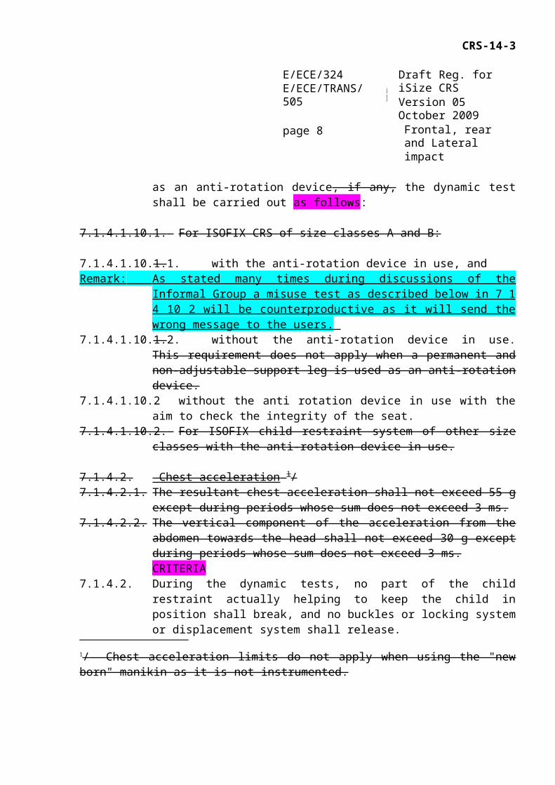
7.1.4.1.10. In the case of an iSize child restraint making use of an ISOFIX anchorage system and a top tether strap as an anti-rotation device, if any, the dynamic test shall be carried out as follows:
7.1.4.1.10.1. For ISOFIX CRS of size classes A and B:
7.1.4.1.10.1.1. with the anti-rotation device in use, andRemark: As stated many times during discussions of the Informal Group a misuse test as
described below in 7 1 4 10 2 will be counterproductive as it will send the wrong message to the users.
7.1.4.1.10.1.2. without the anti-rotation device in use. This requirement does not apply when a permanent and non-adjustable support leg is used as an anti-rotation device.
7.1.4.1.10.2 without the anti rotation device in use with the aim to check the integrity of the seat.
7.1.4.1.10.2. For ISOFIX child restraint system of other size classes with the anti-rotation device in use.
7.1.4.2. Chest acceleration 1/7.1.4.2.1. The resultant chest acceleration shall not exceed 55 g except during periods
whose sum does not exceed 3 ms.7.1.4.2.2. The vertical component of the acceleration from the abdomen towards the head
shall not exceed 30 g except during periods whose sum does not exceed 3 ms.CRITERIA
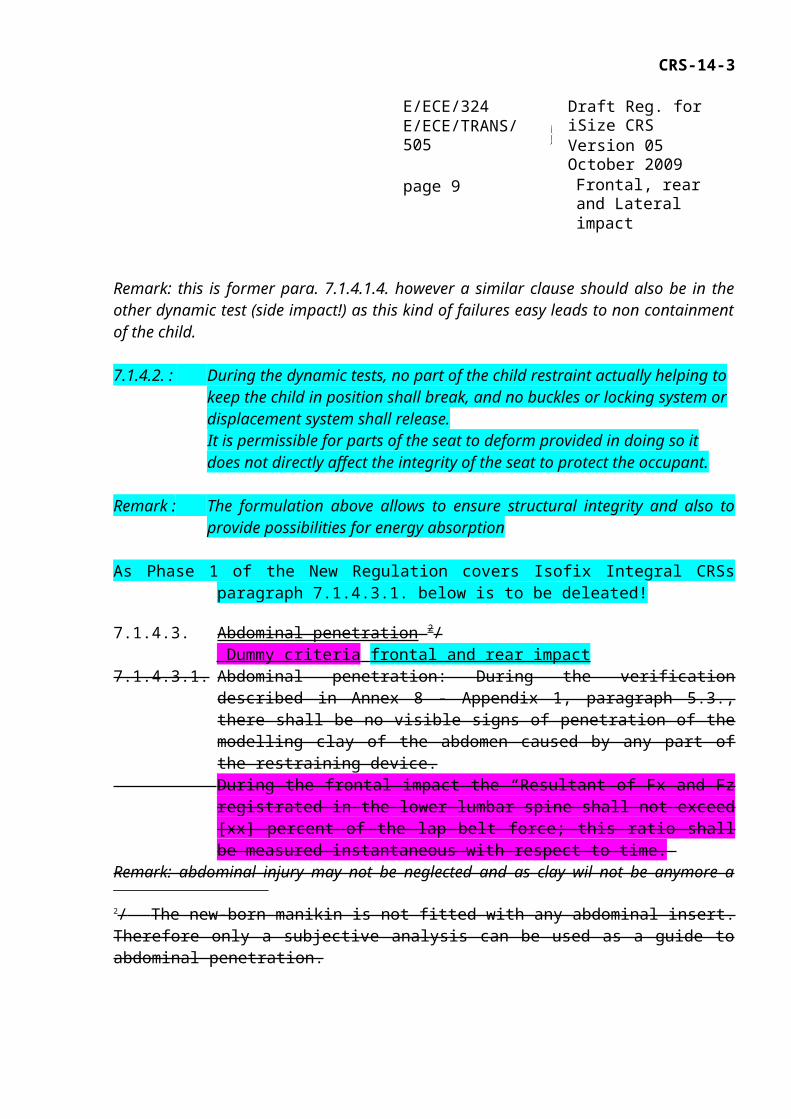
7.1.4.2. During the dynamic tests, no part of the child restraint actually helping to keep the child in position shall break, and no buckles or locking system or displacement system shall release.
Remark: this is former para. 7.1.4.1.4. however a similar clause should also be in the other dynamic test (side impact!) as this kind of failures easy leads to non containment of the child.
7.1.4.2. : During the dynamic tests, no part of the child restraint actually helping to keep the child in position shall break, and no buckles or locking system or displacement system shall release.It is permissible for parts of the seat to deform provided in doing so it does not directly affect the integrity of the seat to protect the occupant.
Remark : The formulation above allows to ensure structural integrity and also to provide
1/ Chest acceleration limits do not apply when using the "new born" manikin as it is not instrumented.
CRS-14-3
E/ECE/324E/ECE/TRANS/505
Draft Reg. for iSize CRSVersion 05 October 2009
page 6 Frontal, rear and Lateral impact
possibilities for energy absorption
As Phase 1 of the New Regulation covers Isofix Integral CRSs paragraph 7.1.4.3.1. below is to be deleated!
7.1.4.3. Abdominal penetration 2/ Dummy criteria frontal and rear impact
7.1.4.3.1. Abdominal penetration: During the verification described in Annex 8 - Appendix 1, paragraph 5.3., there shall be no visible signs of penetration of the modelling clay of the abdomen caused by any part of the restraining device.
During the frontal impact the “Resultant of Fx and Fz registrated in the lower lumbar spine shall not exceed [xx] percent of the lap belt force; this ratio shall be measured instantaneous with respect to time.
Remark: abdominal injury may not be neglected and as clay wil not be anymore a “measuring tool” the focus should be on available tools that could give indications of submarining behaviour that lead to these injuries.In case of a wrong lap belt configuration (that is to say or the lap belt is positioned too high from the beginning or it will slip upwards over the Iliac wings during the frontal impact) the lower lumbar spine load cel will be extra loaded by forces acting in the direction of the impact. Namely not only by the stretching of the dummies (under)legs but also by the pelvis being more rotated when the lap belt intrudes the abdominal section. With regard to this latter point (rotation of pelvis) “angular rate sensors”, which are already used in the head, could also play a role as indicator of submarining of the pelvis.
Remark: Detailed background is needed to understand and judge on feasibility.
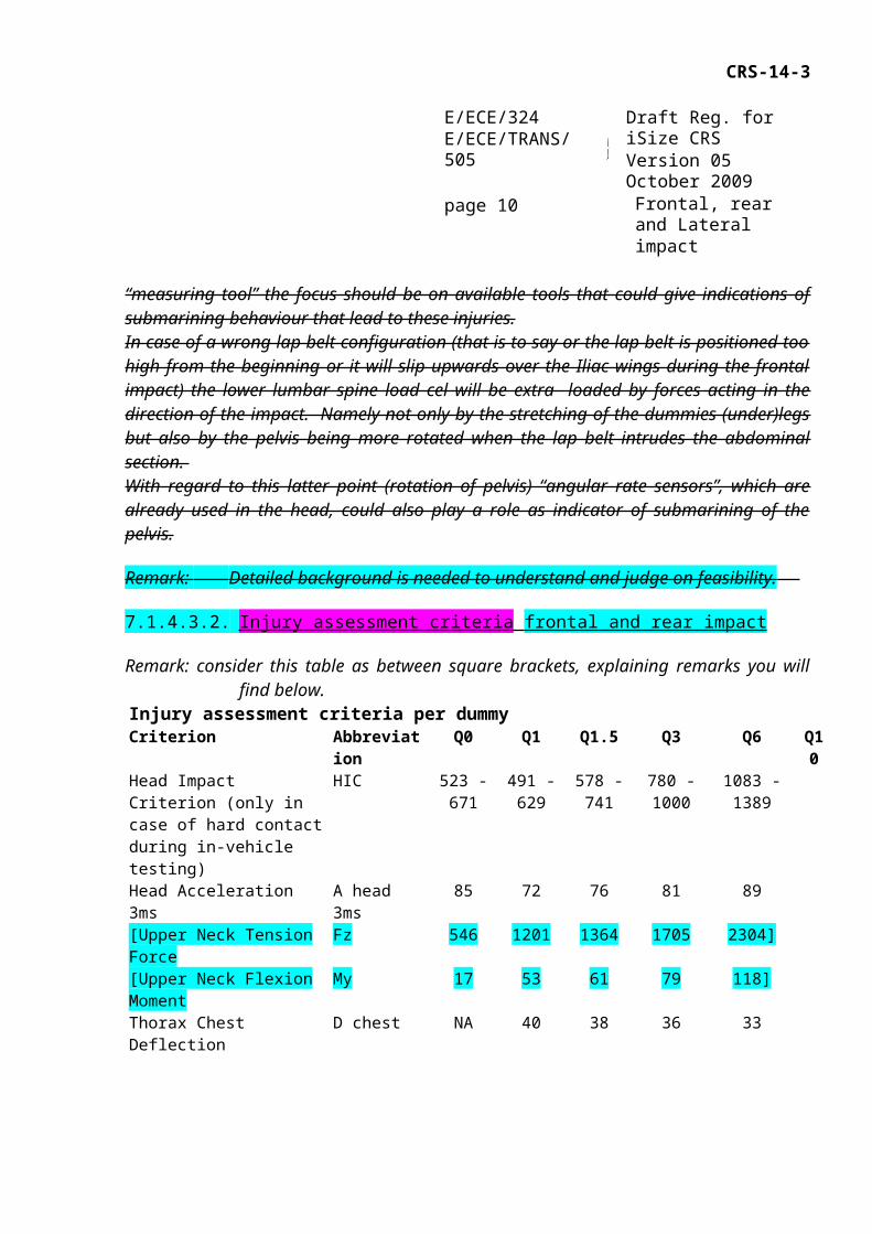
7.1.4.3.2. Injury assessment criteria frontal and rear impact
Remark: consider this table as between square brackets, explaining remarks you will find below.Injury assessment criteria per dummyCriterion Abbreviation Q0 Q1 Q1.5 Q3 Q6 Q10Head Impact Criterion (only in case of hard contact during in-vehicle testing)
HIC 523 - 671
491 - 629
578 - 741
780 - 1000
1083 - 1389
Head Acceleration 3ms A head 3ms 85 72 76 81 89[Upper Neck Tension Force Fz 546 1201 1364 1705 2304][Upper Neck Flexion Moment
My 17 53 61 79 118]
Thorax Chest Deflection D chest NA 40 38 36 33Chest Acceleration 3 ms A chest 3ms 55 55 55 55 55
2/ The new-born manikin is not fitted with any abdominal insert. Therefore only a subjective analysis can be used as a guide to abdominal penetration.
CRS-14-3
E/ECE/324E/ECE/TRANS/505
Draft Reg. for iSize CRSVersion 05 October 2009
page 7 Frontal, rear and Lateral impact
Explaining remarks: The final determination of the injury assessment criteria should lead to child restraints that are significantly better than those child restraints that are just fulfilling the Reg.44 criteria.
Remark: Are Neck Loads criteria defined here compatible with those proposed in 7.1.4.4.1.1.for head excursion limits 500 & 550 mm ?Suggest concentrate on head excursion as key objective, put neck loads in brackets awaiting a strong biomechanical background and feasibility study. A Consistency in the frequency values related to injury assessment criteria (20% or 50%) has to be respected as suggested by EEVC 12 WG
HIC: the herewith presented injury assessment criteria are given as a window and vary between the values that count for 20% and 50% chance on AIS 3+ LR injury, and as stated are only intended for judgement of hard contact during in-vehicle testing;A 3 ms: these are from AIS 3+ 20 % LR injury. Less than 10 % of CRSs tested in the EEVC work failed these criteria. This seems a reasonable level.Fz: Using AIS 3+ 50% injury (read from page 109) of the CRSs tested in the EEVC work still failed this. This seems a difficult level to meet.My: these are from the AIS 3+ 20% LR injury criteria. All CRSs seem to be succesful with regard to these criteria.D chest: these are from the AIS 3+ 20% injury, and 20% of the products tested in the EEVC work would have failed these criteria. Taking account of the fact that this is a new criterion for CRS-testing this seems promissing.A chest 3 ms: for this criterion, there seems to exist some correlation between what is measured with P dummies and Q-dummies. Therefore this criterion is also mentioned in the table above.
7.1.4.4. Manikin ’s head displacement frontal and rear impact
7.1.4.4.1. Child restraints of the "universal", "restricted" and "semi-universal" categories:
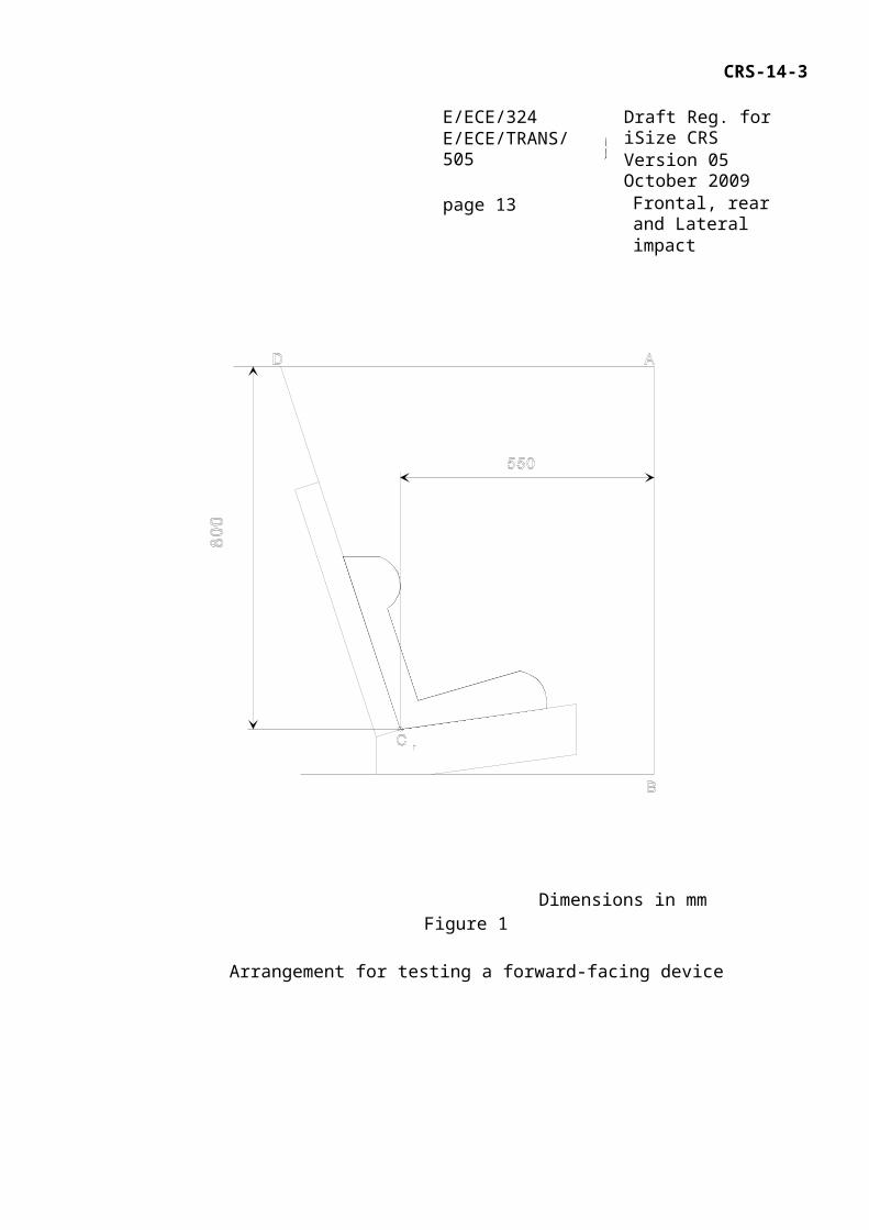
7.1.4.4.1.1. Forward facing child restraints:Head excursion: no part of the head of the manikin shall not pass beyond the planes BA, and DA and DE as defined in Figure 1 below. This shall be judged up to 300 ms or the moment that the manikin has come to a definitive standstill whatever occurs first.
Remark: as is the case with rearward facing child restraints, the point E being the top of the seat back of the R.44 seat should also be defined here.Furthermore, because it concerns ISOFIX child restraints, the forward excursion limit shall have to be changed from 550 mm to 500 mm.Remark The 500 mm head X excursion is compatible with R44/04 dummy performance
criteria such as chest acceleration. Maintaining the same limit with products that have to pass more demanding criteria such as neck loads criteria will be a very difficult task. That compatibility has to be checked before adopting injury criteria.
CRS-14-3
E/ECE/324E/ECE/TRANS/505
Draft Reg. for iSize CRSVersion 05 October 2009
page 8 Frontal, rear and Lateral impact
Finally, the 800 mm vertical limit shall have to be connected to only testing with Q0, Q1, Q1.5, Q3 and Q6, whilst for testing with Q10 a vertical limit of 840 mm will be used.
Dimensions in mmFigure 1
Arrangement for testing a forward-facing device
CRS-14-3
E/ECE/324E/ECE/TRANS/505
Draft Reg. for iSize CRSVersion 05 October 2009
page 9 Frontal, rear and Lateral impact
7.1.4.4.1.2. Rear-facing child restraints:
7.1.4.4.1.2.1. Child restraints supported by dashboard : the head of the manikin shall not pass beyond the planes AB, AD and DCr, as defined in Figure 2 below. This shall be judged up to 300 ms or the moment that the manikin has come to a definitive standstill whatever occurs first.
Remark: figure below with support by dashboard not needed anymore must be deleted
CRS-14-3
E/ECE/324E/ECE/TRANS/505
Draft Reg. for iSize CRSVersion 05 October 2009
page 10 Frontal, rear and Lateral impact
7.1.4.4.1.2.2. Child restraints in group 0 not supported by the dashboard, and carrycots : the head of the manikin shall not pass the planes AB, AD and DE as shown in Figure 3 below. This shall be judged up to 300 ms or the moment that the manikin has come to a definitive standstill whatever occurs first.
Remark: figure below with distance of 600 not needed anymore must be deleted

CRS-14-3
E/ECE/324E/ECE/TRANS/505
Draft Reg. for iSize CRSVersion 05 October 2009
page 11 Frontal, rear and Lateral impact
Figure 3
Arrangement for testing child restraint devices group 0,not supported by the dashboard
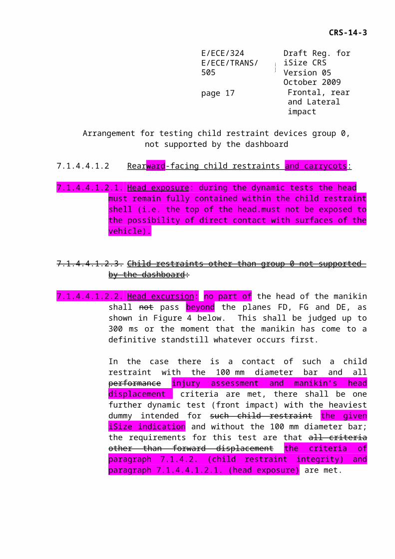
7.1.4.4.1.2 Rear ward -facing child restraints and carrycots :
7.1.4.4.1.2.1. Head exposure : during the dynamic tests the head must remain fully contained within the child restraint shell (i.e. the top of the head.must not be exposed to the possibility of direct contact with surfaces of the vehicle).
7.1.4.4.1.2.3. Child restraints other than group 0 not supported by the dashboard:
7.1.4.4.1.2.2. Head excursion: no part of the head of the manikin shall not pass beyond the planes FD, FG and DE, as shown in Figure 4 below. This shall be judged up to 300 ms or the moment that the manikin has come to a definitive standstill whatever occurs first.

CRS-14-3
E/ECE/324E/ECE/TRANS/505
Draft Reg. for iSize CRSVersion 05 October 2009
page 12 Frontal, rear and Lateral impact
In the case there is a contact of such a child restraint with the 100 mm diameter bar and all performance injury assessment and manikin’s head displacement criteria are met, there shall be one further dynamic test (front impact) with the heaviest dummy intended for such child restraint the given iSize indication and without the 100 mm diameter bar; the requirements for this test are that all criteria other than forward displacement the criteria of paragraph 7.1.4.2. (child restraint integrity) and paragraph 7.1.4.4.1.2.1. (head exposure) are met.
Remark: now from the point of view that a distance from Cr point to dashboard of 700 mm will be an accepted measure, it should be safeguarded that front passenger car seats can offer this space (after normal adjustment of the seat).
7.1.4.4.2. Child restraints of the "specific vehicle" category: when tested in a complete vehicle or a vehicle body shell, the head shall not come into contact with any part of the vehicle. However, if there is contact, the speed of impact of the head
800
380
700
D
C r
F
G
E
Dimensions in mm
Figure 4:Arrangement for testing rearward-facing devices, except group 0,
not supported by the dashboard
Steel tube500 x 100 x 90
Steel tube500 x 100 x 90
CRS-14-3
E/ECE/324E/ECE/TRANS/505
Draft Reg. for iSize CRSVersion 05 October 2009
page 13 Frontal, rear and Lateral impact
shall be less than 24 km/h and the part contacted shall meet the requirements of the energy absorption test laid down in Regulation No. 21, Annex 4. the head impact criterion HIC and the Head Acceleration 3ms shall be used as assessment criteria. In tests with complete vehicles it shall be possible to remove the manikins from the child restraint without the use of tools after the test.
7.1.4.5. Dummy criteria for lateral impact
Remark: Based on CHILD project findings 75% of injuries in side collisions are to the head. It is therefore legitimate to concentrate the performance criterion or criteria for this important body region.
7.1.4.5.1 Main injury assessment criterion - Head containmentDuring the loading phase of lateral impact testing, up to [80] ms, side protection shall always be positioned at the level at the dummy’s head centre of gravity perpendicular to the direction of the door intrusion. This containment will be assessed by a video analysis. Front-on and overhead camera views are assessed.
7.1.4.5.2 During the dynamic tests, no part of the child restraint actually helping to keep the child in position shall break, and no buckles or locking system or displacement system shall release.It is permissible for parts of the seat to deform provided in doing so it does not directly affect the integrity of the seat to protect the occupant.
7.1.4.5.2 Additional Injury assessment criteria
Knowing that the Q Dummy family was not designed for side impact assessment adding other parameters might be useless. However in order to comply with the Informal group goal to ensure energy absorption within the CRS, head acceleration resultant acceleration could be considered.
8. DESCRIPTION OF TESTS 3/
8.1.3. Dynamic tests – for frontal, rear and side impact
3/ Tolerances on dimensions unless otherwise stated, not valid for boundries
Range of dimensions (mm)less than 6above 6 to 30above 30 to 120above 120 to 315above 315 to 1000above 1000Tolerance (mm)± 0.5± 1± 1.5± 2± 3± 4Angular tolerances unless otherwise
stated: ± 1°
CRS-14-3
E/ECE/324E/ECE/TRANS/505
Draft Reg. for iSize CRSVersion 05 October 2009
page 14 Frontal, rear and Lateral impact
8.1.3.1. Tests on the trolley and test seat
8.1.3.1.1. Frontal impact Forward-facing 8.1.3.1.1.1. The trolley and test seat used in the dynamic test shall meet the requirements of
Annex 6 to this Regulation, and the dynamic crash test installation procedure is to be in accordance with Annex 21.
8.1.3.1.1.2. The trolley shall remain horizontal throughout deceleration or acceleration.
8.1.3.1.1.3. Deceleration or acceleration devices
The applicant shall choose to use one of the two following devices:
8.1.3.1.1.3.1. Deceleration test device:
The deceleration of the trolley shall be achieved by using the apparatus prescribed in Annex 6 to this Regulation or any other device giving equivalent results. This apparatus shall be capable of the performance specified in paragraph 8.1.3.4. and hereafter specified:
Calibration procedure:
The deceleration curve of the trolley, in the case of child restraint tests performed in accordance with paragraph 8.1.3.1., ballasted with inert masses up to 55 kg in order to reproduce one occupied child restraint, and in the case of child restraint tests in a vehicle body shell performed in accordance with paragraph 8.1.3.2., where the trolley is ballasted with the vehicle structure and inert masses up to x times 55 kg reproducing the number of x occupied child restraint systems, must remain, in the case of frontal impact, within the hatched area of the graph in Annex 7, Appendix 1 of this Regulation, and, in the case of rear impact, within the hatched area of the graph in Annex 7, Appendix 2 of this Regulation.During calibration of the stopping device, the stopping distance shall be 650 ± 30 mm for frontal impact, and 275 ± 20 mm for rear impact.
Dynamic testing conditions during testing:
For frontal and rear impact the deceleration shall be achieved with the apparatus calibrated as stated above, however:
a) the deceleration curve shall not have a more than 3 ms time duration exceedance of the lower borders of the performance requirements;
b) if the tests above were performed at a higher speed and/or the deceleration

CRS-14-3
E/ECE/324E/ECE/TRANS/505
Draft Reg. for iSize CRSVersion 05 October 2009
page 15 Frontal, rear and Lateral impact
curve has exceeded the upper level of the hatched area and the child restraint meets the requirements, the test shall be considered satisfactory.
8.1.3.1.1.3.2. Acceleration test device
Dynamic testing conditions:
For frontal impact, the trolley shall be so propelled that, during the test, its total velocity change V is 52 + 0 – 2 km/h and its acceleration curve is within the hatched area of the graph in Annex 7, Appendix 1 and stay above the segment defined by the coordinates (5g, 10ms) and (9g, 20ms). The start of the impact (T0) is defined, according to ISO 17 373 for a level of acceleration of 0.5g.
For rear impact, the trolley shall be so propelled that, during the test, its total velocity change V is 32 +2 -0 km/h and its acceleration curve is within the hatched area of the graph in Annex 7, Appendix 2 and stay above the segment defined by the coordinates (5g, 5ms) and (10g, 10ms). The start of the impact (T0) is defined, according to ISO 17 373 for a level of acceleration of 0.5g.
Despite the fulfilment of the above requirements, the Technical Service shall use a mass of trolley (equipped with its seat), as specified in paragraph 1. of Annex 6, superior to 380 kg.
However, if the tests above were performed at a higher speed and/or the acceleration curve has exceeded the upper level of the hatched area and the child restraint meets the requirements, the test shall be considered satisfactory.
8.1.3.1.1.4. The following measurements shall be made:
8.1.3.1.1.4.1. the trolley speed immediately before impact (only for deceleration sleds, needed for stopping distance calculation),
8.1.3.1.1.4.2. the stopping distance (only for deceleration sleds), which may be calculated by double integration of the recorded sled deceleration,
8.1.3.1.1.4.3. the displacement of the manikin's head in the vertical and horizontal planes directionx for groups I, II and III and for group 0 and 0+ the displacement of the manikin without considering its limb of the tests with all Q-dummies necessary for the given iSize indication for at least the first 300 ms,
8.1.3.1.1.4.4. the chest deceleration in three mutually perpendicular directions; except for
new-born manikin the lower lumbar spine loads Fx and Fz [and My], the lap belt force at both sides [and the pelvis angular velocities ωy and ωz] for at least the

CRS-14-3
E/ECE/324E/ECE/TRANS/505
Draft Reg. for iSize CRSVersion 05 October 2009
page 16 Frontal, rear and Lateral impact
first 300 ms,
Remark: 8.1.3.1.1.4.4. is useless as we are dealing here with ISOFIX integral CRSs where submarining is not an issue.
8.1.3.1.1.4.5. any visible signs of penetration of the modelling clay in the abdomen (see paragraph 7.1.4.3.1.); except for new-born manikinthe parameters required to perform the injury assessment against the criteria as mentioned in paragraph 7.1.4.3.2. for at least the first 300 ms,
8.1.3.1.1.4.6. the trolley acceleration or deceleration for at least the first 300 ms.
8.1.3.1.1.5. After impact, the child restraint shall be inspected visually, without opening the buckle, to determine whether there has been any failure or breakage.
8.1.3.1.2. Rear impact Rearward-facing
8.1.3.1.2.1. The test seat shall be rotated 180° when testing in compliance with the requirements of the rear impact test.
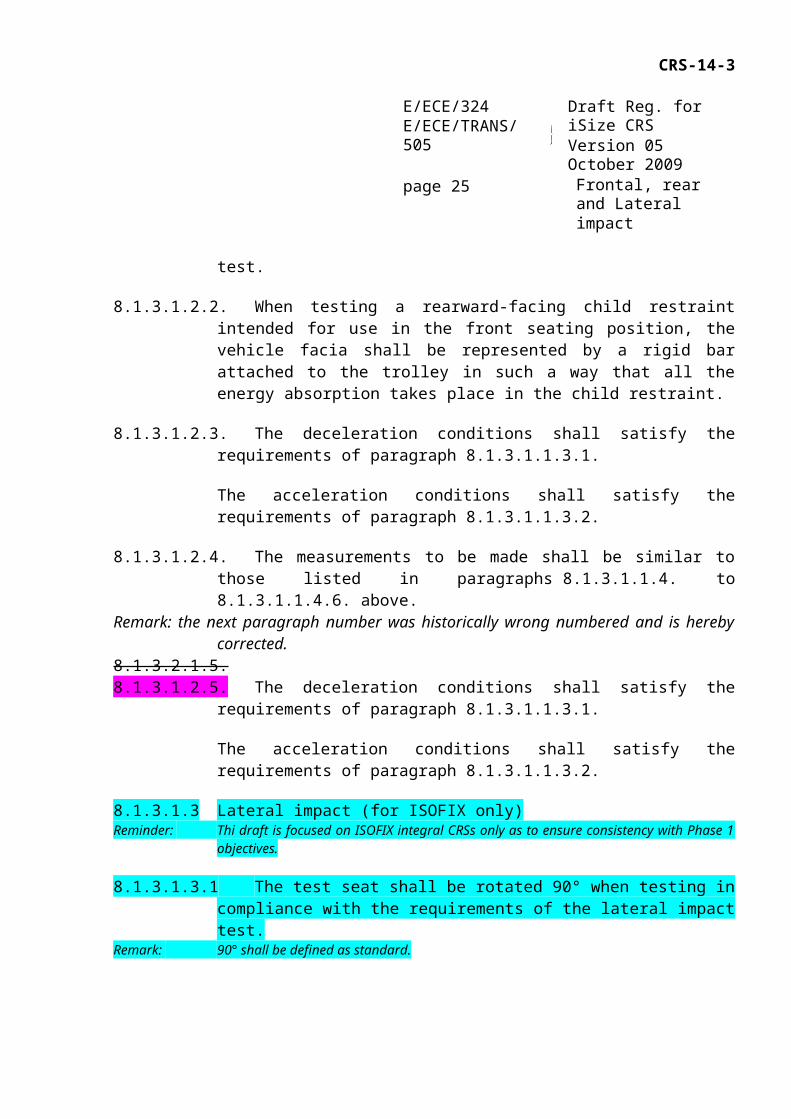
8.1.3.1.2.2. When testing a rearward-facing child restraint intended for use in the front seating position, the vehicle facia shall be represented by a rigid bar attached to the trolley in such a way that all the energy absorption takes place in the child restraint.
8.1.3.1.2.3. The deceleration conditions shall satisfy the requirements of paragraph 8.1.3.1.1.3.1.
The acceleration conditions shall satisfy the requirements of paragraph 8.1.3.1.1.3.2.
8.1.3.1.2.4. The measurements to be made shall be similar to those listed in paragraphs 8.1.3.1.1.4. to 8.1.3.1.1.4.6. above.
Remark: the next paragraph number was historically wrong numbered and is hereby corrected.8.1.3.2.1.5.8.1.3.1.2.5. The deceleration conditions shall satisfy the requirements of
paragraph 8.1.3.1.1.3.1.
The acceleration conditions shall satisfy the requirements of paragraph 8.1.3.1.1.3.2.
8.1.3.1.3 Lateral impact (for ISOFIX only)Reminder: Thi draft is focused on ISOFIX integral CRSs only as to ensure consistency
with Phase 1 objectives.
CRS-14-3
E/ECE/324E/ECE/TRANS/505
Draft Reg. for iSize CRSVersion 05 October 2009
page 17 Frontal, rear and Lateral impact
8.1.3.1.3.1 The test seat shall be rotated 90° when testing in compliance with the requirements of the lateral impact test.
Remark: 90° shall be defined as standard.
8.1.3.1.3.2 The lower ISOFIX anchorages should be movable in the Y direction to avoid damage of the attachments and to the test equipment. The ISOFIX anchorages are individually fixed to a sliding system allowing a movement up to [X] mm.
Remark: In order to protect those specific test devices, the maximum stroke shall not be limited to a level of about 200 mm to avoid high energy impacts on anchorage points, respectively fixture elements of the sled equipment. A maximum stroke will be defined, when respective experience with such a method is gained
8.1.3.1.3.3 The lateral impact loading to the CRS is generated by a door panel as defined in Annex X. [The stiffness and strength of the door panel shall be sufficient to avoid excessive oscillation or significant deformation during lateral dynamic test]. The surface of the panel is covered with padding as specified in Annex X
Remark: The door shall be defined with physical requirements for a clear definition of the test setup.
8.1.3.1.3.4 The test rig shall reproduce a relative velocity between the door panel and the test bench in compliance with Annex 7 Appendix 3. The initial relative velocity between the door panel and the bench is 7 m/s +/- 0.2 m/s. The maximum intrusion depth of the door panel is defined in Annex 7 Appendix 3. The relative velocity between the door panel and the test bench shall not be affected by contact with the CRS and shall remain within the corridor defined in Annex 7 appendix 3.The corresponding velocity – time corridor remains to be established.
8.1.3.1.3.5 The CRS is tested in its most upright position.
8.1.3.1.3.6. At time t0 defined Annex 7 Appendix 3, the dummy must be in its initial position as defined in Annex 21.
8.1.3.1.3.7. Test set-up- CRS Simulation- Dummy installation
8.1.3.2. Test on trolley and vehicle body shell
8.1.3.2.1. Frontal impact Forward-facing
8.1.3.2.1.1. The method used to secure the vehicle during the test shall not be such as to
CRS-14-3
E/ECE/324E/ECE/TRANS/505
Draft Reg. for iSize CRSVersion 05 October 2009
page 18 Frontal, rear and Lateral impact
strengthen the anchorages of the vehicle seats, adult safety belts and any additional anchorages required to secure the child restraint or to lessen the normal deformation of the structure. No part of the vehicle shall be present which, by limiting the movement of the manikin, would reduce the load imposed on the child restraint during the test. The parts of the structure eliminated may be replaced by parts of equivalent strength, provided they do not hinder the movement of the manikin.
8.1.3.2.1.2. A securing device shall be regarded as satisfactory if it produces no effect on an area extending over the whole width of the structure and if the vehicle or structure is blocked or fixed in front at a distance of not less than 500 mm from the anchorage of the restraint system. At the rear the structure shall be secured at a sufficient distance behind the anchorages to ensure that all requirements of paragraph 8.1.3.2.1.1. above are fulfilled.
8.1.3.2.1.3. The vehicle seat and child restraint shall be fitted and shall be placed in a position chosen by the Technical Service conducting approval tests to give the most adverse conditions in respect of strength, compatible with installing the manikin in the vehicle. The position of the vehicle seat-back and child restraint shall be stated in the report. The vehicle seat-back, if adjustable for inclination, shall be locked as specified by the manufacturer or, in the absence of any specification, at an actual seat-back angle as near as possible to 25°.
8.1.3.2.1.4. Unless the instructions for fitting and use require otherwise, the front seat shall be placed in the most forward normally used position for child restraints intended for use in the front seating position, and in the rearmost normally used position for child restraints intended for use in the rear seating position.
8.1.3.2.1.5. The deceleration conditions shall satisfy the requirements of paragraph 8.1.3.4. below. The test seat will be the seat of the actual vehicle.
8.1.3.2.1.6. The following measurements shall be made:
8.1.3.2.1.6.1. the trolley speed immediately before impact (only for deceleration sleds, needed for stopping distance calculation),
8.1.3.2.1.6.2. the stopping distance (only for deceleration sleds), which may be calculated by double integration of the recorded sled deceleration,
8.1.3.2.1.6.3. any contact of the manikin's head with the interior of the vehicle body shell;
8.1.3.2.1.6.4. the chest deceleration in three mutually perpendicular directions; except for new-born manikinthe lower lumbar spine loads Fx and Fz [and My], the lap belt force at both sides [and the pelvis angular velocities ωy and ωz] for at least the first 300 ms lower

CRS-14-3
E/ECE/324E/ECE/TRANS/505
Draft Reg. for iSize CRSVersion 05 October 2009
page 19 Frontal, rear and Lateral impact
lumbar spine loads,Remark: 8.1.3.2.1.6.4. is not needed as we are dealing here with ISOFIX integral CRSs
where submarining is not an issue.
8.1.3.2.1.6.5. any visible signs of penetration of the modelling clay in the abdomen (see paragraph 7.1.4.3.1.) except for new-born manikinthe parameters required to perform the injury assessment against the criteria as mentioned in paragraph 7.1.4.3.2. for at least the first 300 ms,
8.1.3.2.1.6.6. the trolley and vehicle body shell acceleration or deceleration for at least the first 300 ms.
8.1.3.2.1.7. After impact, the child restraint shall be inspected visually, without opening the buckle, to determine whether there has been any failure.
8.1.3.2.2. Rear impact - Rearward-facing
8.1.3.2.2.1. For rear impact tests the vehicle body shell shall be rotated 180° on the test trolley.
8.1.3.2.2.2. Same requirements as for frontal impact.
8.1.3.3. Test with complete vehicle
8.1.3.3.1. The deceleration conditions shall satisfy the requirements of paragraph 8.1.3.4. below.
8.1.3.3.2. For frontal impact tests the procedure shall be that set out in Annex 9 to this Regulation.
8.1.3.3.3. For rear impact tests the procedure shall be that set out in Annex 10 to this Regulation.
8.1.3.3.4. The following measurements shall be made:
8.1.3.3.4.1. the speed of the vehicle/impactor immediately before impact;
8.1.3.3.4.2. any contact of the manikin's head (in the case of group 0 the manikin without considering its limbs) with the interior of the vehicle;
8.1.3.3.4.3. the chest acceleration in three mutually perpendicular directions, except for new-born manikinthe lower lumbar spine loads Fx and Fz [and My], the lap belt force at both sides [and the pelvis angular velocities ωy and ωz] for at least the first 300 ms lower

CRS-14-3
E/ECE/324E/ECE/TRANS/505
Draft Reg. for iSize CRSVersion 05 October 2009
page 20 Frontal, rear and Lateral impact
lumbar spine loads,
8.1.3.3.4.4. any visible signs of penetration of the modelling clay in the abdomen (see paragraph 7.1.4.3.1.), except for new-born manikinany visible signs of penetration of the modelling clay in the abdomen (see paragraph 7.1.4.3.1.); except for new-born manikinthe parameters required to perform the injury assessment against the criteria as mentioned in paragraph 7.1.4.3.2. for at least the first 300 ms.
8.1.3.3.5. The front seats, if adjustable for inclination, shall be locked as specified by the manufacturer or, in the absence of any specification, at an actual seat-back angle as near as possible to 25°.
8.1.3.3.6. After impact, the child restraint shall be inspected visually, without opening the buckle, to determine whether there has been any failure or breakage.
FRONTAL IMPACT REAR IMPACT LATERAL IMPACT
Test Restraint Speed km/h
Test pulse
Stopping distance
during test (mm)
Speed km/h
Test pulse
Stopping distance
during test (mm)
Speed km/h
Test pulse
Stopping distance during test (mm)
[Maximum intrusion]
Trolley with test
seat
forward facing
50+0-2 1 650±50 30+2
-0 2 275±25 25 +/- 1 5 [300]
rearward facing 25 +/- 1 5 [300]
8.1.3.4 The conditions for dynamic test are summarized in the table below:
NOTE: All restraint systems for groups 0 and 0+ shall be tested according to "Rearward-facing" conditions in frontal and rear impact.
LEGEND:Test Pulse No. 1 - As prescribed in Annex 7 - frontal impact. Test Pulse No. 2 - As prescribed in Annex 7 - rear impact. Test Pulse No. 3 - Deceleration pulse of vehicle subjected to frontal impact.Test Pulse No. 4 - Deceleration pulse of vehicle subjected to rear impact.Test Pulse No. 5 Deceleration pulse of vehicle subjected to side impact to be defined.

CRS-14-3
E/ECE/324E/ECE/TRANS/505
Draft Reg. for iSize CRSVersion 05 October 2009
page 21 Frontal, rear and Lateral impact
Note: test procedure for body in white sled test and full vehicle test remain to be defined for phase 1 of the New Regulation.
The paragraph below can be deleted because it has to do with additional anchorages for semi-universal child restraints which will not be part of this new regulation on iSize child restraints.
8.1.3.5. Child restraints incorporating the use of additional anchorages
8.1.3.5.1. In the case of child restraints intended for use as specified in paragraph 2.1.2.3. and incorporating the use of additional anchorages, the requirement for a frontal impact test, in accordance with paragraph 8.1.3.4., shall be carried out as follows:
8.1.3.5.2. For devices with short upper attachment straps, e.g. intended to be attached to the rear parcel shelf, the upper anchorage configuration on the test trolley shall be as prescribed in Annex 6, Appendix 3.
8.1.3.5.3. For devices with long upper attachment straps, e.g. intended for use where there is no rigid parcel shelf and where the upper anchorage straps are attached to the vehicle floor, the anchorages on the test trolley shall be as prescribed in Annex 6, Appendix 3.
8.1.3.5.4. For devices, intended for use in both configurations, the tests prescribed in paragraphs 8.1.3.5.2. and 8.1.3.5.3. shall be carried out with the exception that, in case of the test carried out in accordance with the requirements of paragraph 8.1.3.5.3. above, only the heavier manikin shall be used.
8.1.3.5.5. For rearward-facing devices, the lower anchorage of configuration on the test trolley shall be as prescribed in Annex 6, Appendix 3.
8.1.3.5.6. For carry cots utilizing additional straps that are attached to two adult safety belts, where the load path shall apply directly through the adult safety belt to the adult safety belt lower anchorage, the anchorage on the test trolley shall be as prescribed in Annex 6, Appendix 3, paragraph 7. (A1, B1). Installation on the test bench shall be as described in Annex 21, note 5. This system must work correctly even with the adult safety belts unlocked, and is considered as Universal when complying with paragraph 6.1.8.
8.1.3.6. Test manikins
8.1.3.6.1. The child restraint and manikins shall be installed in such a way that the requirements of paragraph 8.1.3.6.3. are met.
Remark: this is a funny sentence as later on the same level of subparagraphs (6.1.1.6.3.) will be required how the manikin shall be placed etc.

CRS-14-3
E/ECE/324E/ECE/TRANS/505
Draft Reg. for iSize CRSVersion 05 October 2009
page 22 Frontal, rear and Lateral impact
8.1.3.6.2. The child restraint shall be tested using the manikins prescribed in Annex 8 to this Regulation.
8.1.3.6.3. Installation of the manikin
Remark: this installation should be rewritten taking account of the special properties of the Q dummies; the text in the coloured frames are just first thoughts. Experience from NPACS partners and in particular ADAC, who continued with their own rating system using Q-dummies, will be useful.
8.1.3.6.3.1. The manikin shall be placed so that the gap is between the rear of the manikin and the restraint. In the case of carry-cots the manikin is placed in a straight horizontal position as close as possible to the centre line of the carry-cot.
8.1.3.6.3.2. Place the child chair on the test seat.Place the manikin in the child chair, such that:-the dummy head is horizontal following the …- the arms of the dummy are placed following the ….Place a hinged board or a similar flexible device 2.5 cm thick and 6 .. cm wide and of length equal to the shoulder height (sitting, Annex 8) less the hip centre height (sitting, in Annex 8 popliteus height plus half of thigh height, sitting) relevant to the manikin size being tested between the manikin and the seat back of the chair. The board should follow as closely as possible the curvature of the chair and its lower end should be at the height of the manikin's hip joint.
Adjust the belt in accordance with the manufacturer's instructions, but to a tension of 250 ± 25 N above the adjuster force, with a deflection angle of the strap at the adjuster of 45 ± 5°, or alternatively, the angle prescribed by the manufacturer.
Complete the installation of the child chair to the test seat in accordance with Annex 21 to this Regulation.
Remove the flexible device.
This only applies to harness restraints and to restraints where the child is restrained by the adult three-point belt and where a lock-off device is used and does not apply to child restraining straps connected directly to a retractor.
8.1.3.6.3.3. The longitudinal plane passing through the centre line of the dummy shall be set midway between the two lower belt anchorages, however note shall also be taken of paragraph 8.1.3.2.1.3. In case of booster cushions to be tested with the manikin representing a 10-year-old child, the longitudinal plane passing through the centre line of the manikin shall be positioned 75 ± 5 mm to the left or right
CRS-14-3
E/ECE/324E/ECE/TRANS/505
Draft Reg. for iSize CRSVersion 05 October 2009
page 23 Frontal, rear and Lateral impact
with regard to the point midway between the two lower belt anchorages.
8.1.3.6.3.4. In the case of devices requiring the use of a standard belt, the shoulder strap may be positioned on the manikin prior to the dynamic test by the use of a light-weight masking tape of sufficient length and width. In the case of rear-facing restraints, it is permitted to use a light-weight masking tape to connect the dummy’s head to the 100 mm bar or the back of the restraint during the sled acceleration.
8.1.3.7. Category of manikin to be used iSize indicationThe manikin(s) that are used in testing will be the nominator for the iSize indication, that the child restraint may carry, in the following way:
Remark: so the classification of groups will be left and an iSize indication will be introduced. The tabel below is inspired by the segmentation presented in the German document CRS-07-04, that is to say that a test with a certain Q-dummy will provide the indication and that tests with more Q-dummy will simply extend the indication.A certain restriction with respect to mass is not (yet?) taken on board!
8.1.3.7.1. Group 0 device: Test using the "new-born" manikin and a manikin of 9 kg;8.1.3.7.2. Group 0+ device: test using the new-born manikin and a manikin of 11 kg.8.1.3.7.3. Group I device: Tests using a manikin of mass 9 kg and 15 kg respectively;8.1.3.7.4. Group II device: Tests using a manikin of mass 15 kg and 22 kg respectively;8.1.3.7.5. Group III device: Tests using a manikin of mass 22 kg and 32 kg respectively.
8.1.3.7.1. Q0, iSize 40-60,
8.1.3.7.2. Q1, iSize 60-80,
8.1.3.7.3. Q1,5, iSize 70-90,
8.1.3.7.4. Q3, iSize 85-105,
8.1.3.7.5. Q6, iSize 105-130,
8.1.3.7.6. Q10, iSize 130-[150]
8.1.3.7.6. If the child restraint system is suitable for two or more mass groups wider iSize indications than stated above for one dummy, the tests shall be carried out using the lightest and heaviest all manikins specified above for all the groups concerned to create a complete cover of this larger indication. However, if the configuration of the device alters considerably from one group to the next, for instance when the configuration of the harness or the harness length is changed,

CRS-14-3
E/ECE/324E/ECE/TRANS/505
Draft Reg. for iSize CRSVersion 05 October 2009
page 24 Frontal, rear and Lateral impact
the laboratory conducting the tests may, if it deems it advisable, add a test with a manikin of intermediate weight.
8.1.3.7.7. If the child restraint system is designed for two or more children, one test shall be carried out with the heaviest manikins occupying all seat positions. A second test with the lightest and the heaviest manikins specified above shall be carried out. The tests shall be conducted using the test seat as shown in Annex 6, Appendix 3, Figure 3. The laboratory conducting the tests may, if it deems it advisable, add a third test with any combination of manikins or empty seat positions.
8.1.3.7.8. If a child restraint system in group 0 or 0+ offers different configurations depending on the mass of the child, each configuration shall be tested with both manikins of the respective mass group.
8.1.3.7.9. If the ISOFIX child restraint system must use a top tether, one test shall be carried out with the smallest dummy with the shorter distance of the top tether (anchorage point G1). A second test shall be carried out with the heavier dummy with the longer distance of the top tether (anchorage point G2). Adjust the top tether to achieve a tension load of 50 5 N.
8.1.3.7.10. The test specified in paragraph 7.1.4.1.10.1.2. need only be carried out with the largest manikin for which the child restraint is designed.
8.1.4. Restraint of booster cushions
Place a cotton cloth on the seating surface of the test bench. Position the booster cushion on the test bench, position the lower torso body block as described in Annex 22, Figure 1, on the seating surface, fit and apply the 3-point adult safety-belt and tension as prescribed in Annex 21. With a piece of 25 mm width webbing or similar tied round the booster, apply a load of 250 ± 5 N in the direction of arrow A, see Annex 22, Figure 2, in line with the seating surface of the test bench.
8.2. Tests of individual components
Remark: the contents of paragraph 8.2. concerns all kinds of tests for several components and is not taken on board in this piece of work.
CRS-14-3
E/ECE/324E/ECE/TRANS/505
Draft Reg. for iSize CRSVersion 05 October 2009
page 25 Frontal, rear and Lateral impact
8.3. Certification of Test Bench Cushion
8.3.1. The test seat cushion shall be certified when new to establish initial values for impact penetration and peak deceleration, and then after every 50 dynamic tests or at least every month, whichever is the sooner, or before each test if the test rig is used frequently.
8.3.2. The certification and measuring procedures shall correspond to those specified in the latest version of ISO 6487; the measuring equipment shall correspond to the specification of a data channel with a channel filter class (CFC) 60.
Using the test device defined in Annex 17 to this Regulation, conduct 3 tests, 150 ± 5 mm from the front edge of the cushion on the centre line and at 150 ± 5 mm in each direction from the centre line.
Place the device vertically on a flat rigid surface. Lower the impact mass until it contacts the surface and set the penetration marker to the zero position. Place the device vertically above the test point, raise the mass 500 ± 5 mm and allow it to fall freely to make impact on the seat surface. Record the penetration and the deceleration curve.
8.3.3. The peak values recorded shall not deviate by more than 15 percent from the initial values.
Remark: the contents of 8.3. will be replaced by the certification derived from the work done by NPACS.
8.4. Registration of dynamic behaviour
Remark: this paragraph 8.4. shall be reviewed because the new advanced test tools respond to a higher quality level, therefore mutatis mutandis the same should be applicable to the registration proces; the text in the coloured frame is just a first thought.
[8.4.1. In order to determine the behaviour of the manikin and its displacements, all dynamic tests shall be registered according to the following conditions:
8.4.1.1. Filming and recording conditions:
(a) the frequency shall be at least 500 1000 frames per second;
(b) the test shall be recorded on cine film, video or digital data carrier over at least the first 300 ms;
8.4.1.2. Estimation of uncertainty:

CRS-14-3
E/ECE/324E/ECE/TRANS/505
Draft Reg. for iSize CRSVersion 05 October 2009
page 26 Frontal, rear and Lateral impact
Testing laboratories shall have and shall apply procedures for estimating uncertainty of measurement of the displacement of the manikin's head. The uncertainty shall be within + 25 mm.
Examples of international standards of such procedure are EA-4/02 of the European Accreditation Organization or ISO 5725:1994 or the General Uncertainty Measurement (GUM) method.
8.5. The measuring procedures shall correspond to those defined in ISO 6487: 2002. The channel frequency class shall be:
Type of measurement CFC(FH) Cut-off frequency (FN)
Trolley acceleration 60 see ISO 6487:2002 Annex ABelt loads 60 600 see ISO 6487:2002 Annex AChest acceleration 180 600 see ISO 6487:2002 Annex AHead acceleration 1000 [1650]
Upper neck force 600Upper neck moment 600Chest deflection 600
The sampling rate should be a minimum of 10 times the channel frequency class (i.e. in installations with channel frequency class of 1000, this corresponds to a minimum sampling rate of 10000 samples per second per channel). ]
9. TEST REPORTS OF TYPE APPROVAL AND OF PRODUCTION QUALIFICATION
Remark: although an effort has been done to create a good listing of what must be recorded in a test report (see below), it would be a much better approach to provide in a special annex a template of how the required test report must be.
9.1. The test report shall record the results of all tests and measurements including the following test data:
(a) the type of device used for the test (acceleration or deceleration device),(b) the total velocity change,
CRS-14-3
E/ECE/324E/ECE/TRANS/505
Draft Reg. for iSize CRSVersion 05 October 2009
page 27 Frontal, rear and Lateral impact
(c) the trolley speed immediately before impact only for deceleration sleds,(d) the acceleration or deceleration curve during all the velocity change of the
trolley and at least 300 ms,(e) the time (in ms) when the head of the manikin reaches its maximum
displacement during the performance of the dynamic test,(f) the place occupied by the buckle during the tests, if it can be varied, and(g) and any failure or breakage. ,(h) the following dummy criteria: HIC, Head Acceleration 3ms, Upper Neck
Tension Force, Upper Neck Moment, Thorax Chest Deflection and Lower Lumbar Load Cel Force, and
(i) the lap belt force
Remark: the list of data above could be replaced by the requirement that the test report must be formulated according a harmonized test report given in Annex so and so!
9.2. If provisions relating to anchorages contained in Annex 6, Appendix 3, to this Regulation have not been respected, the test report shall describe how the child restraint is installed and shall specify important angles and dimensions.
9.3. When the child restraint is tested in a vehicle or vehicle structure, the test report shall specify the manner of attaching the vehicle structure to the trolley, the position of the child restraint and vehicle seat and the inclination of the vehicle seat-back.
9.4 The test reports of type approval and of production qualification shall record the verification of markings and of instructions on installation and use.
Annex 7
CURVE OF TROLLEY'S DECELERATION OR ACCELERATION,AS FUNCTION OF TIME
In all cases the calibration and measuring procedures shall correspond to those defined in the International Standard ISO 6487:2002; the measuring equipment shall correspond to the specification of a data channel with a channel frequency class (CFC) 60.
CRS-14-3
E/ECE/324E/ECE/TRANS/505
Draft Reg. for iSize CRSVersion 05 October 2009
page 28 Frontal, rear and Lateral impact

CRS-14-3
E/ECE/324E/ECE/TRANS/505
Draft Reg. for iSize CRSVersion 05 October 2009
page 29 Frontal, rear and Lateral impact
Annex 7 - Appendix 1
CURVE OF TROLLEY'S DECELERATION OR ACCELERATION,AS FUNCTION OF TIME
FRONTAL IMPACT
Definition of the different curvesTime (ms) Acceleration (g)
Low corridorAcceleration (g)
High corridor0 - 1020 0 -50 20 2865 20 -80 - 28100 0 -120 - 0

CRS-14-3
E/ECE/324E/ECE/TRANS/505
Draft Reg. for iSize CRSVersion 05 October 2009
page 30 Frontal, rear and Lateral impact
The additional segment (see paragraph 8.1.3.1.1.3.2.) applies only for the acceleration sled

CRS-14-3
E/ECE/324E/ECE/TRANS/505
Draft Reg. for iSize CRSVersion 05 October 2009
page 31 Frontal, rear and Lateral impact
Annex 7 - Appendix 2
CURVES OF TROLLEY'S DECELERATION OR ACCELERATION,AS FUNCTION OF TIME
REAR IMPACT
Definition of the different curves Time (ms) Acceleration (g)
Low corridorAcceleration (g)
High corridor0 - 2110 010 7 -20 14 -37 14 -52 7 -52 070 - 2170 - 0
The additional segment (see paragraph 8.1.3.1.1.3.2.) applies only for the acceleration sled

CRS-14-3
E/ECE/324E/ECE/TRANS/505
Draft Reg. for iSize CRSVersion 05 October 2009
page 32 Frontal, rear and Lateral impact
CRS-14-3
E/ECE/324E/ECE/TRANS/505
Draft Reg. for iSize CRSVersion 05 October 2009
page 33 Frontal, rear and Lateral impact
Annex 7 - Appendix 3
SIDE IMPACT
CURVE OF RELATIVE VELOCITY BETWEEN TROLLEY AND DOOR PANEL AS FUNCTION OF TIME
Remark: The corridor must be defined on experiences of respective test labs.
Definition of Door maximum intrusion
Maximum Intrusion
50 mm
At t0
Bench Centreline
350 mm
CRS-14-3
E/ECE/324E/ECE/TRANS/505
Draft Reg. for iSize CRSVersion 05 October 2009
page 34 Frontal, rear and Lateral impact
Annex X
1. Door panel Definition
The door panel geometry must be in line with the bench definitionDrawing to describe the door will be proposed in line with the NPACS Bench
2. Panel padding specification
2.1 GeneralThe door panel is padded with 55 mm padding material, which has to comply with the performance criteria as described in Annex X 2.3 realised in a test set up as described in Annex X 2.2. Finally an example for material meeting the requirements is described in Annex X 2.4.
2.2 Test procedure for the assessment of panel padding materialThe test set up consists of a simple drop test using a spherical head form. The spherical head form has a diameter of 150 mm and a mass of 6 kg (±0,1 kg). The impact speed is 4 m/s (± 0,1 m/s). The instrumentation should allow the assessment of the time of first contact between the impactor and the sample as well as the head form acceleration at least in direction of impact (Z-direction).The material sample should have the dimensions of 400 X 400 mm. The sample should be impacted in its centre.
2.3 Performance criteria for the padding materialThe time of first contact between sample material and head form (t0) is 0 ms.The impactor acceleration shall not exceed 58 g.

CRS-14-3
E/ECE/324E/ECE/TRANS/505
Draft Reg. for iSize CRSVersion 05 October 2009
page 35 Frontal, rear and Lateral impact
0
5
10
15
20
25
30
35
40
45
50
55
60
0 5 10 15 20 25
time [ms]
acce
lera
tion
[g]
1
2
4
3
Key1 Upper limit of 58 g2 Lower limit for the maximum peak at 53 g (11 to 12 ms)3 Upper limit for the decline of acceleration (15 g at 20,5 ms to 10 g at 21,5 ms)4 Lower limit for the decline of acceleration (10 g at 20 ms to 7 g at 21 ms)Figure B.1 — Corridor for the padding material
2.4 Example of material meeting the test requirements.Using 35 mm rubber cell foam Polychloropren CR4271 at the side of the panel structure and 20 mm Styrodur C2500 on top guarantees to meet the requirements. The Styrodur needs to be replaced after each test.
Remark: [Styrodur C2000 is not available, but 2500 could be an acceptable alternative as is available and used for current testing.]
Overall Test Rig Lay Out