7. Technical Design Information - UNHCR
44
7. Technical Design Information This chapter presents supporting technical design information for the options presented in Chapters 4, 5 and 6. In the design and construction of any latrine it is important to consider the following five key factors: • Accessibility; • Safety; • Comfort and community desires; • Privacy; and • Health. The generic process that should be used in latrine construction is out- lined below: 1. Siting of latrine 2. Excavation of pit or disposal system 3. Laying of slab/pedestal and foundations 4. Construction of superstructure 5. Implementation of O&M arrangements 6. Construction of handwashing facilities 7. Determination of monitoring arrangements 117
Transcript of 7. Technical Design Information - UNHCR

7.
Technical Design Information
This chapter presents supporting technical design information for the options presented in Chapters 4, 5 and 6.
In the design and construction of any latrine it is important to consider the following five key factors:
• Accessibility;
• Safety;
• Comfort and community desires;
• Privacy; and
• Health.
The generic process that should be used in latrine construction is out-lined below:
1. Siting of latrine
2. Excavation of pit or disposal system
3. Laying of slab/pedestal and foundations
4. Construction of superstructure
5. Implementation of O&M arrangements
6. Construction of handwashing facilities
7. Determination of monitoring arrangements
117

EXCRETA DISPOSAL IN EMERGENCIES
7.1 Siting latrinesPerhaps the most important design factor regarding latrine construction is where the latrine should be sited. The following factors are important siting selection criteria; each latrine constructed should be:
• not more than 50m away from dwellings to be served;
• at least 30m away from water-storage and treatment facilities;
• at least 30m away from surface water sources;
• at least 30m horizontal distance from shallow groundwater sources (more in coarse or fissured ground – seek local hydrogeological expertise where possible)*;
• downhill of settlements and water sources, where possible;
• at least 50m away from communal food-storage and preparation areas;
• close to handwashing facilities;
• easily accessible to all intended users including children, old people, pregnant women and disabled people.
*While the figure of 30m is often used to indicate the distance that latrines should be from groundwater sources, the required distance can vary greatly depending on ground conditions. A distance equivalent to 25 days travel time is usually sufficient to reduce concentrations of faecal-indica-tor bacteria (e.g. E-coli) to levels where detection within most samples is unlikely (ARGOSS, 2001). Therefore, the 25-day travel distance defines the ‘safe’ distance from latrines. This distance depends on the soil and rock type. Minimum separation distances for different soil and rock types are given in Table 7.1. As can be seen from the table, 30m separation is adequate for some rock types only; where water flows in fractures within rock, pathogens may be able to travel considerable distances within 25 days and it is not possible to provide a minimum distance in this case.
Siting ‘sanitation corridors’ parallel to and approximately 10m from dwell-ings is a useful way to separate accessible sanitation facilities.
Accessibility is a key issue since this is likely to influence how often latrines are used, and hence whether indiscriminate defecation takes place or not. The design and location of toilets must ensure that they are accessible to all relevant vulnerable groups. Security of users, especially
118

7. TECHNICAL DESIGN INFORMATION
women and children, must also be considered, particularly where com-munal latrines are in place. If necessary, facilities can be lit at night for security and convenience.
Table 7.1. Minimum separation distances for latrines/septic-tanks and groundwater sources
Soil/Rock type Approximate minimum distance (m)
Silt 10*
Fine silty sand 15
Weathered basement (not fractured) 25
Medium sand 50
Gravel 500
Fractured rocks Not feasible to use horizontal separation as protection
* 10m is the minimum distance an infiltration system should be from a water source
7.2 Use of local materials and designs The single most important factor in the selection of construction materials and tools is local availability. There is often a tendency to focus on the use of typical relief-agency materials, such as plastic sheeting, when there may be much better local alternatives available. It is inefficient and inap-propriate to import expensive materials if suitable materials are available locally. Possible construction materials include:
• Wood • Cement
• Grass and leaves • Gravel
• Mud • Sand
• Earth blocks • Corrugated-iron (GI) sheets
• Bamboo • Plastic sheeting
• Bricks • Cloth or sacking
119

EXCRETA DISPOSAL IN EMERGENCIES
Tools are also often available locally, and although these may sometimes be of lower quality than imported ones, they are likely to be much more cost-effective, and the local population will be more accustomed to using them. Heavy equipment, or specialized equipment, may also be available and this may influence the selected construction method as well as the overall technology choice.
The use of local materials and existing designs is to be encouraged for various reasons. Depending on local resources that are readily available in the local community, they can be deployed immediately for quick con-struction in the 1st phase of emergency response – typically for traditional pit latrines. As the emergency response progresses and local conditions are monitored, the move towards the use of improved latrines can be considered.
There is also the added benefit that the resulting technology brought in will be viewed by beneficiaries as a local good. This encourages an enhanced sense of community ownership and helps mobilize local com-munities to undertake repair, maintenance and cleaning.
In many cases community members are capable of designing and con-structing their own facilities if they are provided with appropriate tools and technical advice (see Box 7.1). The construction of a demonstration latrine can be a useful way to show people the stages in construction, and for those who have constructed before to share techniques and ideas with other community members. The team supervising and facilitating the process should ensure that basic design principles are followed and that latrines are technically safe.
A system of rotation of toolkits can also be implemented, with each kit being shared between 10-15 households. The kits are signed over to a representative of the local community. The recipient of the toolkit is then responsible for ensuring that all households wishing to construct latrines have access to the tools, and that they are returned when the house-hold has finished, allowing rotation to the next household. Once all the households have finished construction, the majority of the toolkits are then returned to the implementing agency for use in a new community, and approximately 1 kit per 100 latrines constructed is left with the repre-sentative of the community. This is to allow newly returning families to be able to construct their own latrines, drawing on the advice and knowledge
120
7. TECHNICAL DESIGN INFORMATION
gained by other community members, and for families to replace their latrines when they are full. A typical community toolkit should consist of:
• 1 shovel • 1 hoe
• 1 pickaxe • 1 machete
• 1 metal bucket • 5m of rope
Experience shows that it can take a family as little as four days to con-struct a latrine from local materials, two days to dig the pit, and two days to construct the superstructure. A system of support for those who are unable to construct the latrines for themselves – such as the elderly, people with disabilities, or female-headed households – should also be implemented. This aspect of the programme needs to be carefully moni-tored, to ensure that vulnerable people and their families are not being excluded or exploited.
121

EXCRETA DISPOSAL IN EMERGENCIES
Box 7.1.
Using local designs for latrine structure in Angola
Following the closure of IDP camps in Angola, people started returning home and a public health programme started within the returned communities. Initially, a methodology similar to that used in the camps was adopted whereby concrete-dome latrine slabs were introduced. The budgetary constraints of the programme allowed only one latrine per 20 people, and with the memory of the problems associated with shared latrines in the camps, communities were unenthusiastic about participating unless a solution could be found to allow each household to construct a latrine of their own.
A community consultation and sen-sitization process was carried out to gain a better understanding of what was stopping the families from constructing latrines without external support – and to find an alternative solution. This process led to an understanding that the communities were willing and able to construct traditional family latrines using locally available materials, but they required tools and advice in order to do this.
The implementing agency therefore provided toolkits and technical advice and the community began to construct its own latrines. This approach led to high levels of uptake among returning families and allowed know-how and tools to remain in the community, ensuring that newly returning families would have the opportunity to create basic sanitation infrastructure without the need for further external support. The cost of constructing a latrine using local materials was approximately one ninth of the cost of producing the concrete-domed slabs.
122

7. TECHNICAL DESIGN INFORMATION
Figure 7.1. Traditional latrine using local materials
123

EXCRETA DISPOSAL IN EMERGENCIES
Traditional latrine designs typically consist of a pit, a wooden platform packed with grass and covered with soil, and a timber and grass or mud superstructure (see Figure 7.1). A flexible approach should be taken to allow individuals to incorporate their own variations and preferences. Technical guidance should be given regarding:
• the depth of the pit and need for lining;
• the number and size of pieces of wood needed to ensure the stability of the squatting platform; and
• the need to raise the platform above ground level to prevent damage from surface water.
The advantages and disadvantages of a traditional latrine programme using local materials only are summarized in Table 7.2.
Table 7.2. Advantages and disadvantages of traditional latrines
Advantages Disadvantages/Challenges
Use of locally available materials
Possible contribution to deforestation as trees are harvested to construct the latrine platform; also termites may eat wood unless it is treated with bitumen.
Inexpensive Cleaning of slab more difficult than with concrete slab.
Replicable: can be constructed by the community themselves, while the knowledge and tools stay within the community.
Reliance on mobilization, and thus reliance on the commitment and acceptance of the implementing agency to promote the methodology.
Flexibility of design and process can be adapted by individuals and communities to suit local preferences.
Not all community members or households will be physically or materially able to construct their own latrine. Solutions to enable such households to participate need to be identified and implemented within target communities.
Adaptation of traditional approach to latrine building means that programme emphasizes the use of local knowledge and skills.
124

7. TECHNICAL DESIGN INFORMATION
7.3 Pit excavation and liningMost single pits for household or family use are about 1m across and 3m deep. It is difficult to excavate pits less than 0.9m diameter because there is not enough room for the person to work. However, there is no maxi-mum size for a pit and sizes vary greatly.
The best shape for a pit (in plan view) is circular. Circular pits are more stable because of the natural arching effect of the ground around the hole – there are no sharp corners to concentrate the stresses. Pits with flat sides are much more likely to need supporting and require a bigger area of lining than a circular pit of the same internal volume. However, many communities prefer to excavate square or rectangular pits as their construction is similar to the process used for building domestic houses.
In general, the top 0.5m of a pit should always be lined, but the deci-sion as to whether to line the rest of the pit will depend on the type of soil in which the pit is dug. When a pit is first excavated it may appear stable, and it may be impossible to tell whether or not the walls will collapse after some time. One way in which this can be assessed is to examine other excavations (such as hand-dug wells) in the area. If existing excavations have not collapsed and are not lined, then it is fairly safe to assume that pit-latrine excavations will not need lining. Where there is doubt it is advis-able to line the pit. Table 7.3 suggests the types of soil that, in general, do and do not require lining.
Table 7.3. Lining requirements for different soil types
Soils that require lining Soils that do not require lining
Soft sands and gravels Soils with significant clay content
Unconsolidated soils Most consolidated sedimentary rocks
Filled landSoils with high proportion of iron oxides (laterites)
Compressed mudstones and shales
125

EXCRETA DISPOSAL IN EMERGENCIES
The following are commonly used pit-lining materials:
• Wood – time-consuming and difficult to position cross-struts to provide a proper retaining wall; prone to rotting even when treated (see Figure 7.2).
• Concrete blocks – can be built honeycomb style to allow good infiltration (see Appendix 4.3); circular block moulds can be used for circular pits.
• Bricks/stone – time-consuming but may be a preferred alternative to concrete blocks if locally available (see Figure 7.3).
• Mud blocks – local alternative to concrete blocks or bricks.
• Pre-cast concrete rings – the liquid cannot escape easily unless the ring is made with drainage holes; ring moulds required; expensive (see Figure 7.4).
• In-situ cast concrete – relatively time-consuming to construct mould; no infiltration, therefore pits must be emptied; expensive.
• Sandbags – sand and bags usually locally available and low cost; cement can be used in bags for stability in areas of shallow groundwater (see Box 7.2).
• Oil drums – holes must be made in sides for liquid to infiltrate; small diameter limits diameter of pit size and ease of excavation; corode easily.
• Ferrocement – time-consuming and relatively expensive.
• Corrugated-iron sheets – very little infiltration can take place unless holes made; need support bracing.
• Tyres – requires high quantity of tyres; allows infiltration through spaces and provides stability.
• Bamboo/cane – rots faster than wood and less strong – but may be in more plentiful supply in some areas and encourages community participation and income generation (see Box 7.3).
Pit-lining is most cost-effective where pits are to be emptied regularly.
126

7. TECHNICAL DESIGN INFORMATION
220mm x 35mmx 2.0m poling boards
220mm x 35mm x 2.0m close boarding
Struts locatedallow alternate
positions (approx.0.5m spacing)
100mm x 100mm strut
A second row of struts shouldbe installed if the trench
exceeds 2.0m deep
Struts located allow alternatepositions
Struts locatedallow alternate
positions
180mm x 100mmwaling
180mm x 100mm waling
Wedge upwhere necessary
100mm x 100mm strut
100mm x 100mmstrut
13_EDIE
Timber support systems for deep trench latrines
Figure 7.2. Timber support systems for deep trench latrines
127

EXCRETA DISPOSAL IN EMERGENCIES
Figure 7.3. Brick lined pit
Bricks
Gaps in bricks forliquid penitration
4.0m
75mm approx.(one brick heightabove ground)
Typical view of brick lining
1.0m
2.0m
2.65
m d
eep
pit
0.5m
150mm
15_EDIE
Brick lined pit
Section on A - A
2m0.
5m15
0mm
A
A
1.0m
GL
128

7. TECHNICAL DESIGN INFORMATION
Figure 7.4. Pre-cast concrete ring pit liner
800mm
450m
m
300m
m
700mm 50mm
5-6mm ring binders Suggested mix1 cement: 2 sand: 4 gravel
5-6mm ring binders
5-6mm rebars
5-6mm rebars
14_EDIE
Pre-cast concrete ring pit liner
Liner cross-section
Transparent 3D view to show reinforcement bars
129

EXCRETA DISPOSAL IN EMERGENCIES
Box 7.2.
Sandbag pit-lining in Kenya and Sudan
Sandbags were used to line pits in unstable soils in refugee and IDP camps in NE Kenya and Sudan. These were found to be cheaper, more durable and more stable than the oil-drum liners used previously.
Sandbags are placed within the circular pit with the head-to-tail alignment alternating in each course.
In areas of shallow groundwater, cement was added to the sand mix to increase stability. A dry mix was used when the bags were first filled and a few buckets of water were poured over once the bags were installed in the pit.
3.4m
27_EDIE
1.3m
1.5m Ø Dome shapedconcrete slab (1:2:3)
Slab ringing (1:3)
Sand bag lining142mm thick
130

7. TECHNICAL DESIGN INFORMATION
Box 7.3.
Pit-lining with local materials in Mozambique
In Mozambique in response to floods, latrines were built to accom-modate affected populations. The latrines were located in an area of sandy soils so the excavated pits had to be lined to ensure that they would not cave in. Baskets woven by local women were evaluated against the other options available, and it was decided that this would be the
most viable option for lining the pits. The domed latrine slab was used to cover the pit and other local materials such as grasses and reeds were used to build the superstructure.
The baskets were made out of rigid, dried local grasses (reeds) that are typically used for storing grain. A slightly modified design was first discussed with the women, as a basket with a smaller diameter would accommodate the slab better. Agency staff were able to order a number of baskets and then pick them up. Being rigid and sturdy the sides of the pit did not cave in. It proved to be a relatively cheap solution and was quick to install.
Sizing pits
In order to size pits or tanks it is important to determine the rate at which sludge (including faeces, urine and anal-cleansing material) will accu-mulate, and the rate at which effluent will infiltrate into the surrounding ground. The top 0.5m of a pit should not be filled; this is to allow safe back-filling and to prevent splashing, unpleasant sights and increased incidence of problems with odour and flies.
The approximate size of the pit in m3 can be calculated from the following equation:
131

EXCRETA DISPOSAL IN EMERGENCIES
Where: N = number of users
S = sludge accumulation rate (litres/person/year)
D = design life (years)
A = pit-base area (m2)
If the size of the pit is fixed, the time taken to fill it can be calculated by rearranging Equation 1 to find the design life:
Volume of pit, V = , V = , V (N x S x D) + 0.5A Equation 1
1000
+ 0.5A + 0.5A
Design life, D = (V - 0.5A) x 1000 x 1000 x
(N x S)
Sludge accumulation rates vary greatly and local figures should be obtained if possible. In the absence of local knowledge, Table 7.4 gives guideline sludge accumulation rates for different wastes and condi-tions. In many emergency situations, latrines are subjected to heavy use and excreta and anal-cleansing materials are added much faster than the decomposition rate. For this reason the ‘normal’ sludge rates are increased by 50% for emergency situations.
This method assumes that liquid wastes are absorbed by the surrounding ground. If liquid remains in the pit it will fill much more quickly. This is likely to happen where large volumes of water are used, or where pit walls have a low infiltration capacity. It should also be noted that soil pores become clogged with time, reducing or even stopping infiltration. For this reason, pits should be over-sized rather than under-sized, especially where soil infiltration rates are relatively low.
132

7. TECHNICAL DESIGN INFORMATION
Table 7.4. Suggested maximum sludge accumulation rates
Wastes deposited and conditions
Sludge accumulation rate ‘S’ (litres per person per year)
Stable situationEmergency situation
Wastes retained in water where degradable anal-cleansing materials are used
40 60
Wastes retained in water where non-degradable anal-cleansing materials are used
60 90
Wastes retained in dry conditions where degradable anal-cleansing materials are used
60 90
Wastes retained in dry conditions where non-degradable anal- cleansing materials are used
90 135
Source: Franceys et al., 1992
Note: The term ‘wastes retained in water’ when applied to a pit latrine means that wastes are in a section of the pit below the water-table
7.4 Latrine slabsAn important component of a pit latrine is the latrine slab situated above the pit. The purpose of the latrine slab is to cover the top of the pit and, sometimes, provide a surface on which the user puts their feet. The slab should be able to support the weight of a person, easy to clean and should usually be sloped slightly towards the squat-hole to allow liquid to drain. In the early stages of an emergency, many agencies use pre-moulded plastic squatting plates. These are appropriate for immediate rapid imple-mentation and are often suitable for use in emergency trench latrines, health centres, schools and reception centres. For long-term use, how-ever, it is more efficient to use locally manufactured slabs where possible. Slabs can be made of concrete, wood, ferrocement or plastic. Several options with advantages and disadvantages are presented in Table 7.5.
133

EXCRETA DISPOSAL IN EMERGENCIES
Table 7.5. Comparison of latrine slabs
Slab type Comments
Oxfam Plastic SlabSize 1.2m x 0.8m
Needs no supporting timbers – just ensure the pit edges are stable and place it on hole. Trench must be no more than 1.0m wide as slab length is 1.2m. Includes foot-operated drop-hole cover. A pour-flush toilet pan can be inserted into the slab for water-washed systems.
Monarflex Plastic SlabSize 0.8m x 0.6m
Not big enough for cubicle alone, normally need to construct platform to place slab on which makes it more expensive and time-consuming than the above option. Hole-covers rapidly go missing.
Wooden Slab
Can be quick if materials available locally, not easy to clean. Prone to termite attack and rotting. Can be covered with plastic sheeting to increase life and ease of cleaning. Not a good long-term solution (deforestation issues).
Bush timber and sticks covered by plastic sheeting and covered with packed earth
Fast and cheap, and can be easily upgraded with a SanPlat concrete slab or plastic slab. Diffi cult to keep clean, badly affected by rainfall or people washing in the latrine. Wood rots over time.
Dome Slab1.2m or 1.5m diameter
Needs proper mould, 1 bag of cement (sand and gravel) per slab, no rebar. A good longer-term solution.
SanPlat Slab Size 0.6m x 0.6m
Good for upgrading log/mud slabs. Quick to produce, smaller size, therefore requires less rebar. Can be mass-produced using an all-in-one mould to produce a high-quality, easy-clean surface.
Ferrocement SlabsCan make slabs thinner, therefore cheaper, than traditional concrete slabs.
Concrete Slabvarious sizes
Sand, cement and gravel are usually available and easy to make and clean. Requires rebar, which can be difficult & expensive to purchase. Large slabs are not easily transportable.
Plywood SlabWater-resistant ply is very expensive. Not always easy to purchase.
134

7. TECHNICAL DESIGN INFORMATION
In societies where people are not used to squatting to defecate, wherever possible toilet pedestals should be used instead of latrine slabs. Locally manufactured pedestals may be available in plastic or wood.
Concrete is usually the preferred material for latrine slabs for second-phase implementation as it is cheap, durable, easy to clean and sim-ple to manufacture. Most concrete slabs are reinforced with steel bars to prevent breaking; reinforcing bars should be placed near the base of the slab to carry the tension forces. The amount of reinforcement will depend on the size of the slab and the load to be carried. Table 7.6 gives suggestions for the minimum amount of reinforcement required for differ-ent slabs. The last two columns give the preferred spacing of reinforcing bars. Slabs may be rectangular or circular.
Table 7.6. Spacing for steel reinforcing bars in pit-latrine slabs
Slab thickness (mm)
Steel bar diameter (mm)
Spacing of steel bars (mm) in each direction for minimum spans of:
1m 1.25m 1.5m 1.75m 2m
65 6 150 150 125 75 508 250 250 200 150 125
80 6 150 150 150 125 75
8 250 250 250 200 150
The squat-hole in the latrine slab should be large enough to allow def-ecation and urination without fouling the floor, whilst being small enough for the young and old to span and use in safety. Ideally, this should be a ‘keyhole’ shape, 160-170mm in diameter and 300-400mm at full length.
Figure 7.5. gives an example of a reinforced concrete latrine slab.
135

EXCRETA DISPOSAL IN EMERGENCIES
Figure 7.5. Reinforced concrete latrine slab
136

7. TECHNICAL DESIGN INFORMATION
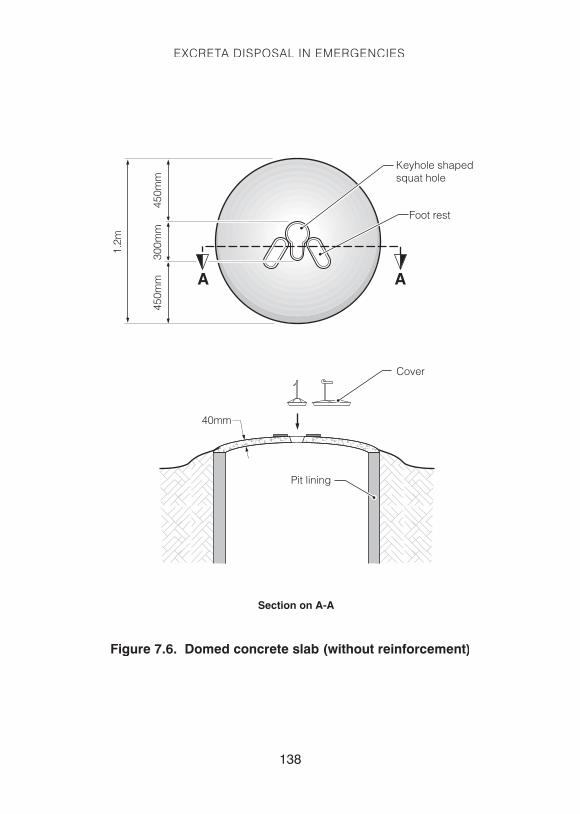
Slabs without reinforcement can be made provided the slab is domed. The dome shape causes all the forces in the slab (apart from the rim) to be compressed so reinforcement is not needed. Although not essential, a couple of rounds of steel wire can be embedded in the concrete close to the rim, as this is the only part of the slab under tension. Domed slabs are cheaper than reinforced slabs but more care is required in their manufac-ture and transport. Such slabs have a typical diameter of 1.2-1.5 metres (see Figure 7.6).
Concrete mixesConcrete is a mix of cement, sand, gravel (aggregate) and water. Gener-ally, one of the two following design mixes is used:
Cement: Sand: Aggregate
1: 2: 4 Mix 1
1: 3: 6 Mix 2
Mix 1 will be slightly stronger than Mix 2 due to the increased proportion of cement. In both cases gravel makes up approximately 60% of the vol-ume of concrete. The ratio of water to cement is generally:
Water: Cement:
1: 2 or
1: 3
Once the concrete is poured into the mould it must be compacted to eliminate voids (air-holes). This can be done manually by using a wooden plank to pound the concrete surface.
The final stage of concrete preparation is curing – this simply means keeping the concrete damp while it sets. Concrete can be cured by cov-ering, regular spraying or submerging in water.
The strength and workability of concrete is affected by the:
• concrete mix;
• water/cement ratio; and
• the curing process.
137
EXCRETA DISPOSAL IN EMERGENCIES
EDIE_17B
Domed concrete slab (without reinforcement)
Section on A-A
1.2m
300m
m45
0mm
450m
m
40mm
Pit lining
Foot rest
Cover
Keyhole shapedsquat hole
AA
Figure 7.6. Domed concrete slab (without reinforcement)
138

7. TECHNICAL DESIGN INFORMATION
Wooden slabs can also be used where concrete is too expensive or is unavailable. Wooden slabs can consist of whole poles covered in mud or soil, or can be sawn-timber platforms (see Figure 7.8). Pits with wooden slabs can be improved by placing a small concrete slab on top to cover the area used for defecation. The slab is quite small (typically 400mm x 600mm) but it covers the area of slab most likely to be fouled. Alter-natively, if wooden slabs are to be used, put a thin covering of cement, approximately 25mm thick, on top to facilitate cleaning.
Squat-hole coversThe squat-hole cover for a simple pit latrine is designed to cover the hole when not in use, to minimize flies and odour. A common problem con-cerning these covers is that they are often not replaced on the hole after use. This may be due to worries of faecal-hand contamination, or may be because covers are taken away for alternative uses.
In some cases, the cover is designed with a long handle, or is tied with a piece of string to the surrounding superstructure. One option is to use a hinged cover which can be opened and closed with the use of an attached piece of string, by hand, or even with the user’s foot (see Figure 7.7). The hinges can be made from old tyre rubber, which is available in most situ-ations. The rubber hinges can be attached to the reinforcement within a concrete latrine slab, or tied to the wooden poles of a wooden slab.
GEN004
Figure 7.7. Squat-hole cover
139

EXCRETA DISPOSAL IN EMERGENCIES
Wedge on underside oflid shaped to fit in hole
Drophole
60mm x 150mmcross beam paintedwith bituminous orkerosene oil
25 x 38 x 200-250mmfloor boards
Lid
250
350
25
38
38500
300
200
18_EDIE
Wooden slab for twin compartment latrine
Drop hole detail
Lid detail side elevation
Lid detail plan
200
100
100
300
300
1.5m
2.0m
350
1.2m
Timber Quantity1 60 x 150 x 1500mm joists across pit 32 38 x 200 x 2000mm floor board 63 25 x 250 x 350mm lid board 24 25mm doa x 500mm lid handle 2
Hardware5 75mm tall wire-nails 426 Bituminous or kerosene (to render watertight and 0.5 ltr against termites.
Note: Actual dimensions will depend on wooden planksavailable. Dimensions indicated are suggested minimum values.
Figure 7.8. Wooden slab for twin compartment latrine
140

7. TECHNICAL DESIGN INFORMATION
7.5 Pour-flush toilet pansWhere people are accustomed to using water-based excreta disposal systems, pour-flush latrines should be installed rather than dry-pit latrines wherever possible.
For immediate emergency use, plastic latrine slabs are also available with built-in pour-flush pans (as pictured below), while there are others which are able to accommodate a pour-flush ‘insert’ which fits into the normal keyhole-shaped drop-hole.
Locally manufactured pour-flush pans should be used where possible, particularly where these are available in plastic and can be transported easily. Concrete pour-flush pans can also be constructed using appropri-ate moulds and incorporated into latrine slabs (see Figure 7.9). Where latrines are to discharge wastewater to a septic-tank or sewerage system it is important that pans are compatible with available pipework (com-monly ranging from 75mm to 120mm diameter).
Photograph 7.1 Plastic pour-flush latrine slab
141

EXCRETA DISPOSAL IN EMERGENCIES
Photograph 7.2. Cement pour-flush pan
Photograph 7.3. Plastic pour-flush pan and lid
142

7. TECHNICAL DESIGN INFORMATION
EDIE_17A
Ferrocement slab with pour-flush bowls(for use on 800mm ø pre-fab concrete ring)
800
B
B
A A
Chicken mesh
Section on B-B
Section on A-A
Chicken mesh
1010
20
40
20
10
10
330
10 10
40 50
300
300
800
250
25010
10 10
170
100
110
Foot rest
Keyholeshapedpour flushbowl
Figure 7.9. Ferrocement slab with pour-flush bowls (for use on 800mm ø pre-fab concrete ring)
143

EXCRETA DISPOSAL IN EMERGENCIES
7.6 Superstructure designTo the user, the superstructure is likely to be the most important part of the latrine. For this reason alone, due attention must be given to its design. In some cultures people prefer to defecate in the open and a superstruc-ture may not be required. In general, however, the superstructure must provide the necessary privacy for the comfort and dignity of the users. Materials and techniques used for the superstructure should generally be the same as those used for people’s shelters, as this will facilitate ease of construction.
In areas of high rainfall, or for VIP latrines, a roof will be essential, although roofing materials may be stolen where shelter is a priority. In other situ-ations roofs may not be necessary. The superstructure may have a door where desired, or a spiral-shaped entrance can be constructed. The superstructure can, more or less, be of any size and shape that the user desires, although a minimum base area of 1m2 is recommended.
Although the superstructure has little direct impact on the health ben-efits of the latrine (with the possible exception of a VIP latrine), its design is likely to influence whether the latrine will be used and looked after. It is essential, therefore, that the users are involved in the superstructure design, to ensure that it is socio-culturally acceptable and to promote the user’s pride in their toilet.
Many superstructure options, using different wall materials, rely on a tim-ber frame (as in Figure 7.10).
144

7. TECHNICAL DESIGN INFORMATION
1.2m1m
300
Back post
Purlin
Diagonal tie
Nail to attach wall plastic sheeting(can use folded pads of plastic toprevent the sheet ripping)
Long tie top purlin
Back post
Front post
Diagonal post
Long tie bottom
Rafter
Cross tie
Frontpost
Rafter
1.8
m
2m
19_EDIE
Timber frame for trench latrine superstructure
1m
1m
1m
Frame Quantity1 Front post 50 x 50 x 2000mm 52 Back post 50 x 50 x 1800mm 53 Cross tie 25 x 50 x 1200mm 5 4 Diagonal tie 25 x 50 x 1800mm 55 Long tie bottom 25 x 75 x 3700mm 26 Long tie top 25 x 75 x 4400mm 27 Vitall (plastic sheet) (3700 + 1300) x2 x 1650= 16.5m2
8 2” (50mm) wirenail 10 x 5 509 1” (25mm) bottom pin for wall fixing 250gms
Roof1 Rafter 38 x 50 x 2000mm 52 Purlin 25 x 50 x 4400mm 33 Roof cover 2000 x 4400mm 8.8m2
4 2” tin screw 30
Note: Actual dimensions will depend on available timber styles.Dimensions indicated are suggested minimum values.
Figure 7.10. Timber frame for trench latrine superstructure
145

EXCRETA DISPOSAL IN EMERGENCIES
Lightweight (portable) superstructuresWhere temporary facilities are required, in particular where people are likely to move from one area to another, lightweight superstructures that can be easily disassembled and moved are ideal. One solution is to develop a superstructure frame using PVC piping, which can then be fitted with cloth or plastic sheeting. This approach was used in Burma where refugee migrant workers move around looking for work took their latrines with them!
Superstructures using local materials Although plastic sheeting is a common option for rapid construction of the superstructure, it often creates a hot, uncomfortable interior, rips easily and can be damaged by strong winds. Where possible, locally available materials should be used. A number of options for latrine superstructure design using local materials are presented in Figures 7.12 and 7.13.
Figure 7.11. PVC-pipe superstructure frame
146

7. TECHNICAL DESIGN INFORMATION
Roof covering in bamboo,twigs or branches
Fly screen(aluminium orstainless steelmesh)
20-25mm mud-cowdungplaster on both sides
Wattle wall
Spiral entrance
Dome shape thatched roof
Vent pipe
1.2m
0.6m
20_EDIE
Superstructure for family VIP latrine with spiral entrance
2.5m
2.0m
Note: Approximate dimensions only
Figure 7.12. Superstructure for family VIP latrine with spiral entrance
147

EXCRETA DISPOSAL IN EMERGENCIES
Figure 7.13. Low-cost latrine superstructure
Thatched roof
Mud plasteringfortified withcow dung
Natural twine
Bamboo or woodsuperstructure
Walls made fromreeds or branches
Earth mound
Tight fitting lidfor drop hole
21_EDIE
Low-cost latrine superstructure
Prefabricated-superstructure units
Unlike latrine slabs, there are few well-designed prefabricated units avail-able for superstructures. Prefabricated-plastic superstructures used in northern Uganda were not liked by many users since they were hot and poorly ventilated. Once they were no longer required they also created a solid-waste problem. Tent-style superstructures have also been devel-oped but these have limited applicability and durability.
The International Federation of Red Cross and Red Crescent Societies (IFRC) has recently developed a plastic superstructure unit that can be deployed for rapid implementation in the immediate stage of an emer-gency. Each unit can be erected in minutes and, since it is self-support-ing, can be installed directly on top of a dug pit. Existing prefabricated latrine slabs (such as the Monarflex) can be fitted directly on to the treated
148

7. TECHNICAL DESIGN INFORMATION
plywood base. Although these units are relatively expensive they may be an appropriate option where facilities need to be installed very rapidly and where there are few local resources available for superstructure con-struction.
Superstructure design should also consider the need for privacy for men-struation. In Pakistan, combined ‘hygiene units’ were used for excreta disposal and menstruation-cloth washing and drying (see Box 7.4).
Box 7.4.
Screened hygiene units in Pakistan
Living in close proximity to other people in a camp situation will be a new experience for many people; for women who previously lived in rural areas and in seclusion it will pose additional challenges. As part of the emergency public health response to the Pakistan earthquake of October 2005, screened bathing and toilet units were constructed in some camps. This was felt to be particularly important because many of the women who were living in the camps had previously been living in Purdah (seclusion).
These units consisted of:
• Trench latrines divided into individual units with wooden frames and tarpaulin coverings and doors with simple locks made of binding wire.
• Several individual bathing units which consisted of 20mm (¾”) marble slabs sloping towards a stone-filled drain which, in turn, sloped towards a rubble-filled soakpit.
149

EXCRETA DISPOSAL IN EMERGENCIES
• On top of the soakpit was a metal water container with a tap which was filled daily and was used for handwashing.
• On the side of the handwashing container a sock was tied which included pieces of cut-up soap to encourage the use of soap for washing hands – sometimes the soap went missing, but there were some successes where it remained. It was always the aim that, wherever possible, the handwashing container and soakage pit would be placed next to the exit door to try and encourage people to use the water for handwashing after using the toilet.
• For some units an additional hygiene unit was also included which consisted of a private screened area within the outer screened area. These had a concrete slab with a pipe to a soak-away in which women could wash their menstrual cloths in private. Several washing-lines were also hung across the units and the sides of the units were raised where there was any risk of people looking over and seeing the menstrual cloths hung out to dry.
• The ground within the screened area was covered in broken gravel chippings to prevent mud when it rained and to try and ensure that the units remained hygienic.
• A catchment drain was constructed on the upper side of the units.
Both men’s and women’s toilet and bathing units were screened and both proved successful. Whilst it was probably more necessary for the women’s units to be screened for added privacy, it was also felt to be good practice for the men’s units to be screened. The men also faced a lack of privacy in the camps and – if they bathed in the open – this would also lead to added discomfort for the women who either had to go past them or avoid them.
Had the water-availability situation been better and the soakage capacity of the pits and soak-aways been higher, then the screened units could have been expanded to include a tap inside the units, a concrete drainage curtain to a soak-away and, possibly, hot water via a burner unit and some form of drum with tap. An intensive cleaning programme was required to maintain the units. Female cleaners were employed to clean women’s units, and male cleaners to clean men’s units.
(See next page for design details of the screened units)
150

7. TECHNICAL DESIGN INFORMATION
Figure 7.14. Women's latrine/washroom screened units for camps
35_EDIE
Women’s hygiene units
4.2m
3.2m
1.2m 0.8m1m
1.0m 0.3m1.0m1.2m1.2m
3m
1.0m
1.2m
0.8m 0.8m 0.8m
Latrines
Pit
Washrooms
Women’s sanitarytowel washing anddrying areaBuried drainage pipe
Stone filled drainagechannel which should
be within the wash roomunits and under the covered
roof area.
Hand-washing barrel with tap and soap(broken into pieces to try and prevent itbeing stolen, and hung in a sock or smallsack tied to the hand washing barrel).
The barrel should ideally be standing onthe soak-pit and near to the exit door of thescreened areas (as a reminder for peopleto wash their hands).
Sloping concrete ormarble slabs placed on
a bed of sand, with smoothfinish for easy cleaning.
Soakawaypit
Gravel area
Entranceand Exit
See Appendix 4.8 for the relevant bill of quantities.
151

EXCRETA DISPOSAL IN EMERGENCIES
The need to consider access for disabled people is also important when designing latrine superstructures (see Box 7.5).
Box 7.5.
Designing for disabled people in Pakistan
In Pakistan – in response to the October 2005 earthquake – selected trench latrine cubicles were doubled in size to allow for wheelchair access and, later, a commode chair was placed over the squat-holes. Bedpans were also provided for people who were immobile and unable to leave their beds to use the toilet.
152

7. TECHNICAL DESIGN INFORMATION
Box 7.6.
Bathing and latrine facilities after the Bam earthquake in Iran
Following the Bam earthquake in December 2003, in the initial emergency phase aid agencies implemented shallow-pit latrines and communal trench latrines but these were not widely accepted. There was, therefore, a need to find a more acceptable longer-term option.
The local custom in Bam was to construct two pour-flush latrines per house, one inside and the other in the courtyard, both connected to deep unlined pits – with an average pit depth of 20m. So the agencies decided that the quick but long-lasting solution would be to provide appropriate portable superstructures for the outside latrines, which could be recovered and cleaned from the rubble in the family courtyards.
They called for a joint tender to design and construct an appropriate superstructure locally. Several options were presented, using materials such as fibreglass, canvas and galvanised iron, but the selected design was an aluminium cabin. Over the course of two months 234 aluminium cabins were installed as toilets; users were very satisfied with the design, which was also approved by Government. The decision to fabricate the cabins locally in Bam acted as a big booster for the revival of the local economy, and helped build the capacity and skills of local artisans.
Superstructures must be locally appropriate and, where traditional emer-gency facilities are not acceptable, it may be necessary to seek non-tra-ditional solutions through consultation with the intended users and local artisans (see Box 7.6).
153

EXCRETA DISPOSAL IN EMERGENCIES
7.7 Septic-tank designFor septic-tanks to function properly it is essential that they are designed and operated correctly. The design stages for a septic-tank are outlined below:
1. Choose a suitable location – this should be downhill from the source of sewage, at least 30m from the nearest water supply and at least 30m from the nearest water supply and at leastat least 3m from the nearest building. Avoid areas where rainwater would stand or flow over the tank or vehicles could drive over it. (Draw a plan showing the septic-tank and distances to dwellings, property lines, wells, water sources and any other prominent man-made or natural features. Show the ground slope. See Figure 7.18.)
2. Calculate volume of wastewater to be treated per day – this can be determined by estimating toilet visits per day and water used per flush. If the quantity of water supplied to the toilet block or institution to be served is known then the daily wastewater flow can be taken as 90% of daily water supply. This should be monitored where possible, before and after construction, as an increase in wastewater flow (such as a result of additional sullage) will affect the retention time and may mean that the septic-tank does not function properly.
3. Decide on a retention time (R) – this is based on daily wastewater flow and can be determined from Table 7.7.
Table 7.7. Recommended septic-tank retention times
Daily wastewater flow Retention time ‘R’ (hours)
Less than 6m3 24
Between 6 and 14m3 33 – 1.5Q
Greater than 14m3 12
4. Determine tank volume (T) using the following equation:
Total tank volume (T) = clear-liquid retention volume (A) + sludge and scum volume (B) + ventilation space (V)
154

7. TECHNICAL DESIGN INFORMATION
A = Q x R/24
Where: A = liquid retention volume (m3)
Q = volume of wastewater treated per day (m3)
R = tank retention time (hours)
B = P x N x S x F
Where: P = Number of people using the system
B = sludge storage capacity in litres
N = the number of years between sludge emptying
S = rate of sludge and scum accumulation
(S = 25 litres per person per year for tanks receiving WC waste only, and 40 litres per person per year for tanks receiving WC waste and sullage. As a rule of thumb, two thirds of storage volume is for sludge and a third for scum.)
F = Sludge-digestion factor (see Table 7.8)
Table 7.8. Sludge-digestion factors ‘F’
Years between desludging
Average air temperature
Greater than 20oC all year
Between 10oC and 20oC all year
Less than 10oC in winter
1 1.3 1.15 2.5
2 1.0 1.15 1.5
3 1.0 1.0 1.27
4 1.0 1.0 1.15
5 1.0 1.0 1.06
6 or more 1.0 1.0 1.0
155

EXCRETA DISPOSAL IN EMERGENCIES
Ventilation volume (V) is the volume of air space required between the top of the liquid and the base of the cover. This should be a depth of 300mm, hence the volume will depend on the tank dimensions.
The tank should be divided into two compartments, the first of which should be twice as long as the second. The total length should be approx-imately three times the width, W. The tank depth should be at least 1.2m and, ideally, 1.5m. It should not exceed three times the width.
34_EDIE
Basic tank dimensions
Firstcompartment
Secondcompartment
2W W
Depth 1.2m minimum,1.5m ideal, 3W max
W(0.6m min)
Figure 7.15. Basic tank dimensions
For a tank depth of 1.5m the required width, W can be found from:
Note: This equation can be used only for a depth of 1.5m (with a vent space of 300mm) and if the tank length is equal to 3W.
If the calculated value of W is less than 0.6m, then 0.6m should be used instead.
Septic-tank construction The walls of the tank can be made of poured, reinforced concrete, stone masonry, brick or concrete blocks. The tank should be made water-tight with a 25mm coating of cement plaster, applied in two coats, in order to avoid infiltration around the tank and maintain an anaerobic space. The
156

7. TECHNICAL DESIGN INFORMATION
base should be at least 150mm thick and should be reinforced (except for very small tanks). The roof of the tank can be made of removable sec-tions with lifting handles (for easy access) or a solid, reinforced concrete roof with round access holes (minimum diameter 0.6m). These provide access to the tank for desludging, checking wastewater levels and main-tenance. If the tank will be below the groundwater level at any time the weight of the empty tank should be greater than the weight of water dis-placed, otherwise the tank may float (see Section 6.1).
Inlet and outlet pipes consist of ‘T’ pipes. On the outlet this is to avoid scum or solids going into the soakfield. On the inlet this is to reduce turbulence. The base of the tank can slope down towards the inlet in a large tank to allow more sludge to be stored at the inlet end. The outlet on a larger tank can be a weir design. The inlet wastewater pipe should be ventilated above head height in order to allow the gases produced in the tank to escape.
See Figure 7.16 for septic-tank design details and Appendix 4.9 for a bill of quantities for a septic-tank.
Soakfield designThe effluent from a septic-tank still contains pathogens and must be dis-posed of into a sewerage system or alternative disposal system such as a reed-bed, soakpit or soakfield (infiltration field). A soakfield consists of a series of 15-30m long trenches with open-jointed 100mm diameter pipes laid on rocks, broken bricks or gravel.
The top of the pipe should be laid about 50mm under a layer of building paper/straw (see Figure 7.17). The bottom of the trench should be at least 1.5m above the water-table and have a minimum slope of 2%. Pipes can be made porous by making them out of concrete without sand, not seal-ing the joints or, in the case of plastic pipes, cutting slots or holes in them (at least 6mm in diameter).
The trenches should be narrow (0.3-1.0m) and deep (1.5-2.0m) and arranged in series so that each trench overflows into the next one. Trenches should be approximately 2m apart. The length of the trench can be calculated using the formula below:
Length (m) = number of users x wastewater flow (l/person/day)
2 x effective depth (m) x infiltration rate (l/m2/day)
157

EXCRETA DISPOSAL IN EMERGENCIES
Figure 7.16. Septic-tank design
158

7. TECHNICAL DESIGN INFORMATION
The infiltration rate can be estimated from Table 7.9.
Table 7.9. Suggested infiltration rates
Type of soil Infiltration rate (l/m2/day)
Coarse / medium sand 50
Fine sand, loamy sand 33
Sandy loam, loam 25
Porous silty clay / porous silty clay loam 20
Compact silty loam, compact silty clay loam and non-expansive clay
10
Expansive clay <10
Regular monitoring is required – if the septic-tank is not functioning prop-erly solids may enter and block the infiltration pipes.
Figure 7.17. Soakfield trench
159

EXCRETA DISPOSAL IN EMERGENCIES
Figure 7.18. Septic-tank location plan
160