7-Segment.pptx
16
Seven Segment Displays Digital Electronics
-
Upload
shreyansjainrs -
Category
Documents
-
view
2 -
download
0
Transcript of 7-Segment.pptx

Seven Segment Displays
Digital Electronics

Seven Segment Displays
Retro LED Watch
(Circa 1970s)
This presentation will demonstrate how• A seven-segment display can be used to display the
decimal numbers 0-9 and some alpha characters.• A common anode seven-segment display works.• A common cathode seven-segment display works.• To select the resistor value for a seven-segment display.
2

Segment Identification• A Seven-Segment Display (SSD) is simply a figure eight
grouping of LEDs {some include a decimal point (DP)}.• Each Segment is labeled (a) thru (g).• SSDs are available in two configurations
– Common Cathode (all LED cathodes are connected)– Common Anode (all LED anodes are connected)
a
b
c
d
e
g
dp
f
3
SSD Display PossibilitiesDecimal Digits 0-9
Simple Messages
Select Alpha Characters
4
Basic LED Operations
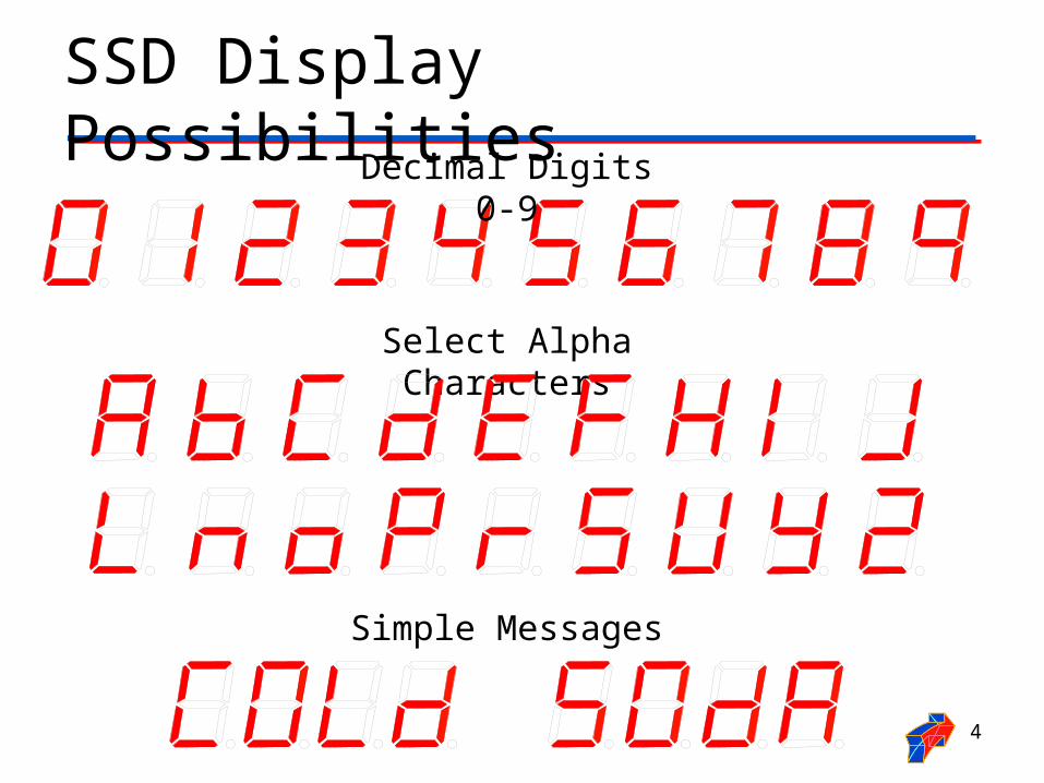
To Turn an LED ON . . .
• The ANODE must be at a higher voltage potential (1.5v) than the CATHODE.
• The amount of current flowing through the LED will determine the brightness of the LED.
• The amount of current is controlled by a series resistor. (not shown)
To understand how a seven-segment display works, we must review how an LED works.
CATHODE (‒) (+) ANODE
← Current Flow
5

LED Configuration – Anode @ 5 Volts
Switch @ 5v• Top Circuit• LED Off
Switch @ 0v• Bottom Circuit• LED On• ANODE @ 5v• CATHODE @ 0v (nearly)• The 220 resistor controls the
current.• A larger resistor . . . less current .
. . dimmer LED• A smaller resistor . . . more
current . . . brighter LED
Common AnodeConfiguration
(5v=Off / 0v=On)
6
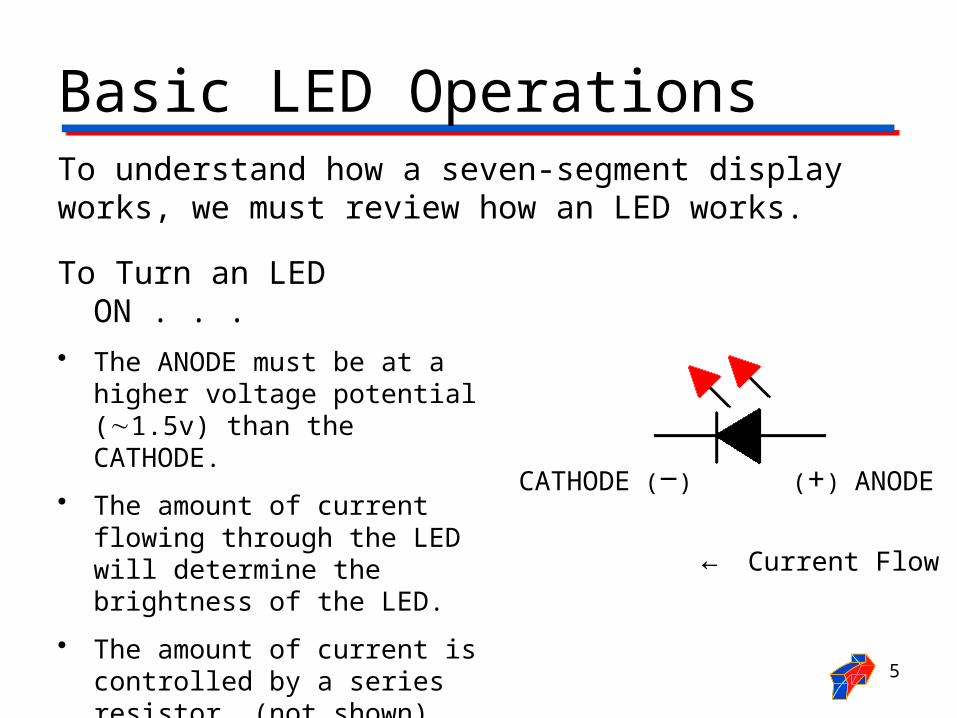
Example #1: Common Anode SSDExample
What value would be displayed in the common anode seven-segment display shown?
7
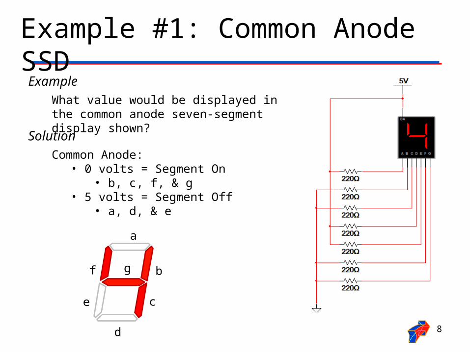
Example #1: Common Anode SSDExample
What value would be displayed in the common anode seven-segment display shown?
Solution
Common Anode:• 0 volts = Segment On
• b, c, f, & g• 5 volts = Segment Off
• a, d, & e
a
b
c
d
e
gf
8

LED Configuration – Cathode @ Ground
Switch @ 5v• Top Circuit• LED On• ANODE @ 5v (nearly)• CATHODE @ 0v• The 220 resistor controls the
current.• A larger resistor . . . less
current . . . dimmer LED• A smaller resistor . . . more
current . . . brighter LED
Switch @ 0v• Bottom Circuit• LED Off
Common Cathode SSD Configuration (5v=On / 0v=Off)
9

Example #2: Common Cathode SSDExample
What value would be displayed in the common cathode seven-segment display shown?
10
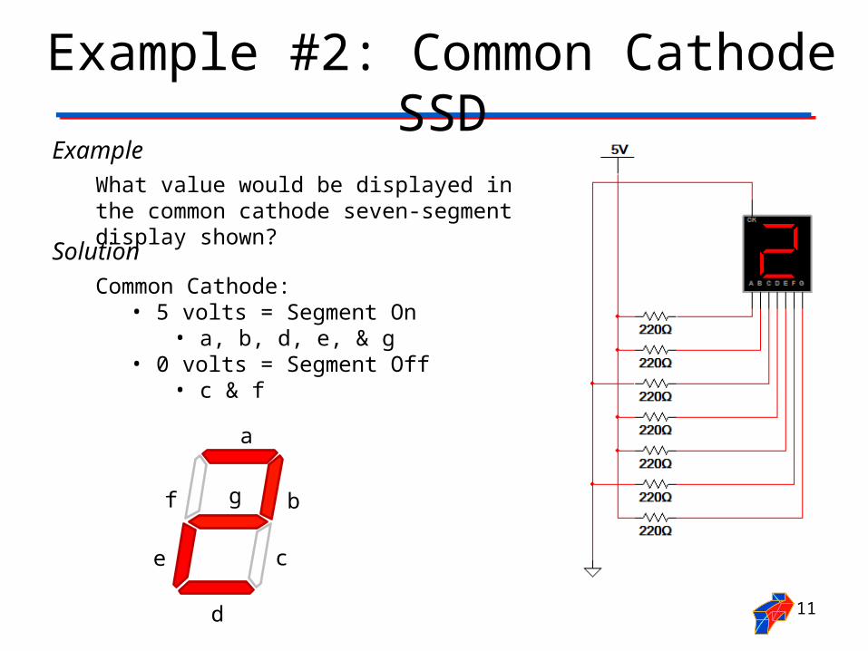
Example #2: Common Cathode SSDExample
What value would be displayed in the common cathode seven-segment display shown?
Solution
Common Cathode:• 5 volts = Segment On
• a, b, d, e, & g• 0 volts = Segment Off
• c & f
a
b
c
d
e
gf
11

Resistor Values for SSD• The resistor value determines the amount of current that
is flowing through the LED in the SSD.
• This is why they are sometimes called current limiting resistors.
• The amount of current determines how luminous (bright) the LED will be.
• If the resistor is too large, the current will be too small and the LED will not be visible.
• If the resistor is too small, the current will be too large and the LED will be damaged.
• So, how do you select the correct value? You must read the data sheet for the SSD that you are using. 12
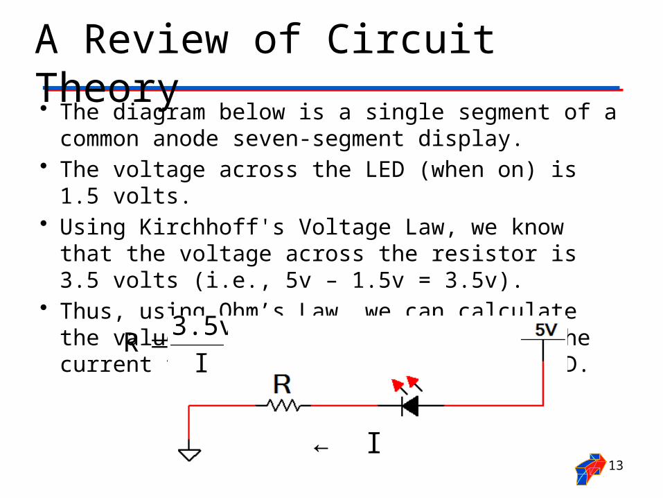
A Review of Circuit Theory• The diagram below is a single segment of a common
anode seven-segment display.• The voltage across the LED (when on) is 1.5 volts.• Using Kirchhoff's Voltage Law, we know that the voltage
across the resistor is 3.5 volts (i.e., 5v – 1.5v = 3.5v).• Thus, using Ohm’s Law, we can calculate the value of the
resistor if we know the current that is to flow through the LED.
I
3.5vR
← I13
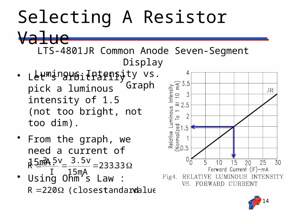
Selecting A Resistor Value
• Let’s arbitrarily pick a luminous intensity of 1.5 (not too bright, not too dim).
• From the graph, we need a current of 15mA.
• Using Ohm’s Law :
LTS-4801JR Common Anode Seven-Segment DisplayLuminous Intensity vs. Forward Current Graph
value) standard (closest 220R
33.23315mA
3.5v
I
3.5vR
14
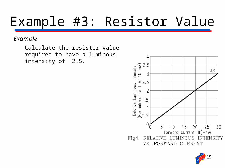
Example #3: Resistor ValueExample
Calculate the resistor value required to have a luminous intensity of 2.5.
15
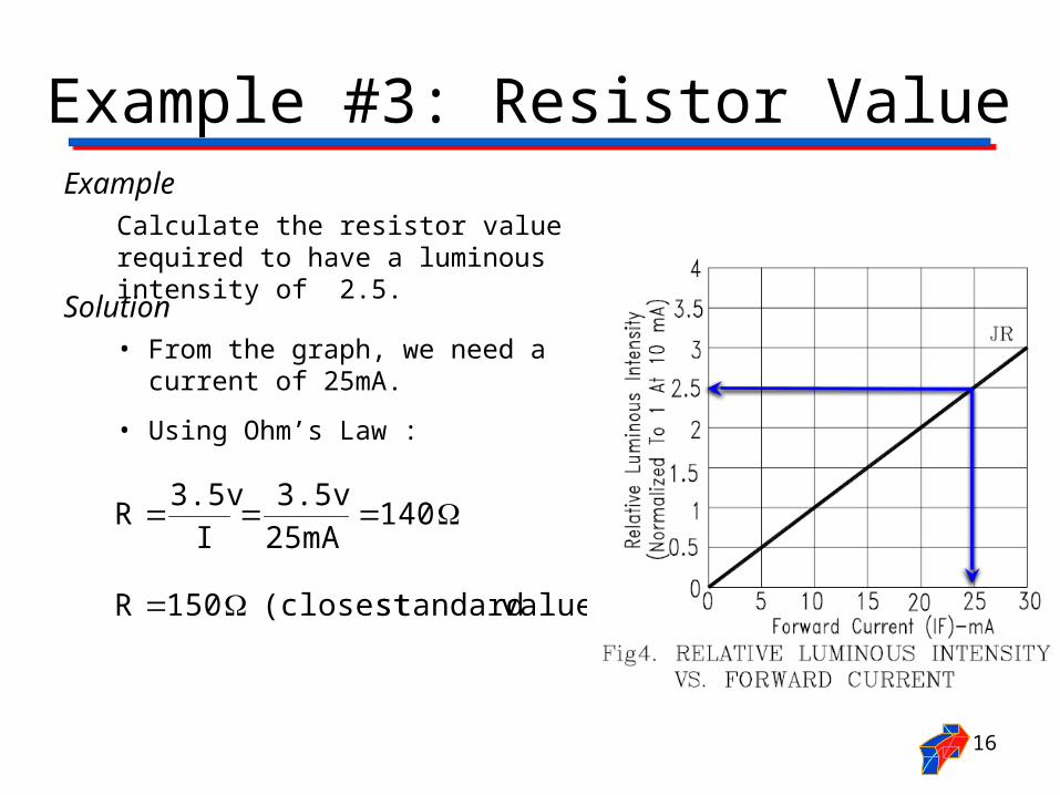
Example #3: Resistor ValueExample
Calculate the resistor value required to have a luminous intensity of 2.5.
Solution• From the graph, we need a
current of 25mA.
• Using Ohm’s Law :
value) standard (closest 150R
14025mA
3.5v
I
3.5vR
16


![University of Aveiro, Portugal palmeida@ua · 7 7 7 7 7 7 7 7 7 7 7 7 5: is LT-superregular by blocks. jFjis very large. Can be used in Network Coding [Mahmood, Badr, Khisti, 2015].](https://static.fdocuments.in/doc/165x107/5fd5938c11949f2fc04395ea/university-of-aveiro-portugal-palmeidaua-7-7-7-7-7-7-7-7-7-7-7-7-5-is-lt-superregular.jpg)
![[XLS]dev.eiopa.europa.eu · Web view2 6 6 7/7/2014 8 7/7/2014 1 7 7 7/7/2014 9 7/7/2014 1 8 8 7/7/2014 10 7/7/2014 1 9 9 7/7/2014 11 7/7/2014 1 10 10 7/7/2014 12 7/7/2014 1 11 11](https://static.fdocuments.in/doc/165x107/5ae5800d7f8b9a8b2b8bf1f3/xlsdeveiopa-view2-6-6-772014-8-772014-1-7-7-772014-9-772014-1-8-8-772014.jpg)