7. Geometrical optics Human eye - UZH -...
15
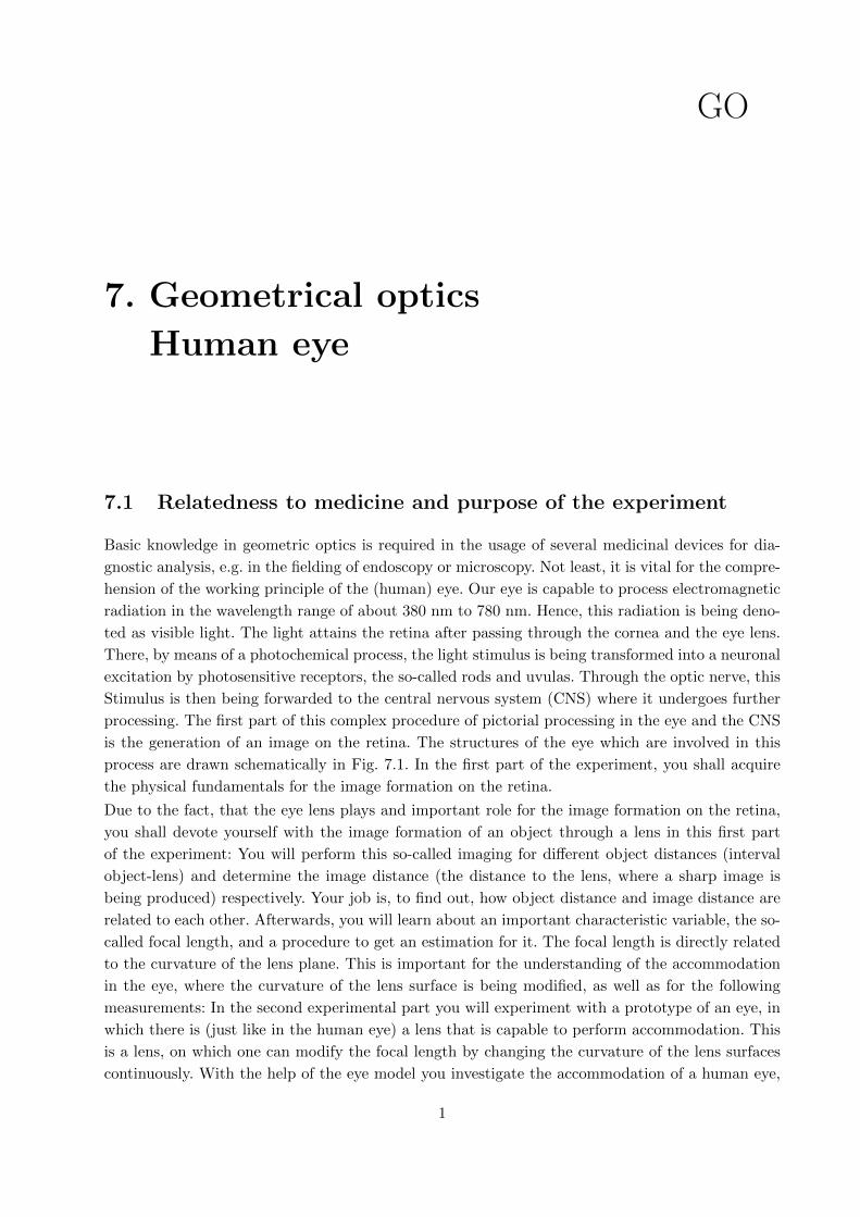
7. Geometrical optics Human eye GO 7.1 Relatedness to medicine and purpose of the experiment Basic knowledge in geometric optics is required in the usage of several medicinal devices for dia- gnostic analysis, e.g. in the fielding of endoscopy or microscopy. Not least, it is vital for the compre- hension of the working principle of the (human) eye. Our eye is capable to process electromagnetic radiation in the wavelength range of about 380 nm to 780 nm. Hence, this radiation is being deno- ted as visible light. The light attains the retina after passing through the cornea and the eye lens. There, by means of a photochemical process, the light stimulus is being transformed into a neuronal excitation by photosensitive receptors, the so-called rods and uvulas. Through the optic nerve, this Stimulus is then being forwarded to the central nervous system (CNS) where it undergoes further processing. The first part of this complex procedure of pictorial processing in the eye and the CNS is the generation of an image on the retina. The structures of the eye which are involved in this process are drawn schematically in Fig. 7.1. In the first part of the experiment, you shall acquire the physical fundamentals for the image formation on the retina. Due to the fact, that the eye lens plays and important role for the image formation on the retina, you shall devote yourself with the image formation of an object through a lens in this first part of the experiment: You will perform this so-called imaging for different object distances (interval object-lens) and determine the image distance (the distance to the lens, where a sharp image is being produced) respectively. Your job is, to find out, how object distance and image distance are related to each other. Afterwards, you will learn about an important characteristic variable, the so- called focal length, and a procedure to get an estimation for it. The focal length is directly related to the curvature of the lens plane. This is important for the understanding of the accommodation in the eye, where the curvature of the lens surface is being modified, as well as for the following measurements: In the second experimental part you will experiment with a prototype of an eye, in which there is (just like in the human eye) a lens that is capable to perform accommodation. This is a lens, on which one can modify the focal length by changing the curvature of the lens surfaces continuously. With the help of the eye model you investigate the accommodation of a human eye, 1
Transcript of 7. Geometrical optics Human eye - UZH -...
7. Geometrical optics
Human eye
GO
7.1 Relatedness to medicine and purpose of the experiment
Basic knowledge in geometric optics is required in the usage of several medicinal devices for dia-
gnostic analysis, e.g. in the fielding of endoscopy or microscopy. Not least, it is vital for the compre-
hension of the working principle of the (human) eye. Our eye is capable to process electromagnetic
radiation in the wavelength range of about 380 nm to 780 nm. Hence, this radiation is being deno-
ted as visible light. The light attains the retina after passing through the cornea and the eye lens.
There, by means of a photochemical process, the light stimulus is being transformed into a neuronal
excitation by photosensitive receptors, the so-called rods and uvulas. Through the optic nerve, this
Stimulus is then being forwarded to the central nervous system (CNS) where it undergoes further
processing. The first part of this complex procedure of pictorial processing in the eye and the CNS
is the generation of an image on the retina. The structures of the eye which are involved in this
process are drawn schematically in Fig. 7.1. In the first part of the experiment, you shall acquire
the physical fundamentals for the image formation on the retina.
Due to the fact, that the eye lens plays and important role for the image formation on the retina,
you shall devote yourself with the image formation of an object through a lens in this first part
of the experiment: You will perform this so-called imaging for different object distances (interval
object-lens) and determine the image distance (the distance to the lens, where a sharp image is
being produced) respectively. Your job is, to find out, how object distance and image distance are
related to each other. Afterwards, you will learn about an important characteristic variable, the so-
called focal length, and a procedure to get an estimation for it. The focal length is directly related
to the curvature of the lens plane. This is important for the understanding of the accommodation
in the eye, where the curvature of the lens surface is being modified, as well as for the following
measurements: In the second experimental part you will experiment with a prototype of an eye, in
which there is (just like in the human eye) a lens that is capable to perform accommodation. This
is a lens, on which one can modify the focal length by changing the curvature of the lens surfaces
continuously. With the help of the eye model you investigate the accommodation of a human eye,
1

2 Geometrical optics
anterior chamber
cornea
pupil
iris
sphincter
lensretina
macula
vitreous body
derma
choroid
optic nerv
blind spot
Abbildung 7.1: Structure of the human eye.
i.e. the way to focus on objects in different distances. The limit of the accommodation capability
in the close-up range determines the near point. Besides, the eye model is capable to simulate an
“emmetropic”, a “myopic” (shortsighted) or an “hyperopic” (farsighted) eye. 1 Our goal is to get
to know the different consequences of those forms of ametropia (defective vision) and how to treat
them with suitable glasses.
7.2 Test execution
7.2.1 Properties of lenses
Qualitative Considerations
One can generate images with lenses which is one of their important properties. For example, the
lens of the eye generates an image of the observed object on the retina. Those kind of pictures, which
occur on the retina, a screen or a film of a camera are called real images. They are characterized
by the fact that all rays which are coming from an object are crossing each other in one point – the
image point. The entirety of all image points or pixels defines the real image. The prerequisite for
this situation is, that the picturing system forces the divergent ray bundle of the object to focus in
one point.
Only real images can be detected on the retina, a film or a screen!
In contrary, many optical systems, e.g. diffuser lenses or flat mirrors, produce virtual images. The
bundle of rays from the object does not run together but apparently comes off another point (the
1A third form of defective vision, the presbyopia, is being discussed in Part 7.3, Physikalische Grundlagen (German
version)only.
Geometrical optics 3
simplest example is an usual mirror). The totality of all those new points constitutes the so-called
virtual image. To convert such a virtual image into a real image, one needs another imaging system,
e.g. the eye or a camera.
� Through a diffuser lens (lens no. 2), observe an object which lies on the table. What is the
orientation of the object? Is it enlarged or scaled-down?
� Utilize a condenser lens (f = 100mm) as a loupe by looking at a font. Again, describe the
image.
� With the same lens, you can generate a real image by looking at an object, which is faraway.
Hows does the image looks like now?
� At which object distance does the transition from a virtual to a real image happen? (appro-
ximately)
� A loupe and a condenser lens always produce virtual images. Concluding your observati-
ons, what can you say about orientation (upright or reversed) of virtual and real images
respectively?
Virtual image:
Reel image:
Real imaging on a screen
For a further study of image formation, the following tools are available at the work station:
– An optical bench with a (black) lamp with an iris diaphragm (= variable pinhole aperture),
– a lens “f = 100 mm”,

4 Geometrical optics
– two lenses (1) and (2),
– an object (diapositive),
– a scale,
– as well as a matt screen, a mirror and a circular orifice.
First, the object shall be mapped on the screen with the aid of lens no. 1. Therefore, object, lens
and screen shall be fastened in place on the slider which can be moved on the optical bench. Try to
sharpen the image of the object on the screen by moving the lens and/or the screen. 2 The distance
from the middle of the lens to the object is denoted as the object distance g and the distance
from the middle of the lens to the screen (where the image is being created) one names the image
distance b .
diffusing screen
fg
lens screen
b
G
light source
F2F1
Abbildung 7.2: Image of an object by a thin condenser lens.
� Does this image have the same properties like the real image you had created before?
� Now, change the object distance and again and focus for maximum image sharpness. How
did the image and the image distance change?
Such kinds of changes shall explored systematically in the following:
2As long as the image has not reached the maximum sharpness, it is not reasonable to speak of an image distance
or an image size. Therefore, before reading out those quantities, set up an image as sharp as possible. Notice, that
every movement of a component has an influence on the image definition.
Geometrical optics 5
� Image the object for at least 5 different (preferably widely spread) object distances g with
maximum sharpness. Make sure you obtain both down-scaled and up-scaled images! For each
object distance g , measure the associated image distance b and fill in the results in the
following table.
object– and image distance for lens no. 1.
g [cm]
b [cm]
� How does the image distance change when you increase the object distance?
� How does the image size behave?
Focal length of lenses
� Using lens no. 1, check how and whether the image distance changes when you set up very
large object distances. Write down your observations.
You probably discovered that the image distance hardly changes in case of large object distances
whilst moving the object even further away from the lens. The image distance has a lower threshold,
which is characteristic for the particular lens and which is denoted as its focal length f . For a
situation where the object would lie “infinitely far” away from the lens and therefore one would
have an “infinitely large” object distance, one would measure exactly this lower threshold as focal
length which would now equal the image distance.
� For the largest possible object distance on the optical bench, measure the image distance and
state it as a (rough) estimate for the focal length of lens no. 1:
estimated focal length of lens (1):
The light rays, which emerged from the object that lies far away, run parallel to each other and
parallel rays 3 are going to be imaged in the focus when sent through a condenser lens.
3More exact: Rays, that run parallel to the so-called optical axis, see Part 7.3, Physikalische Grundlagen (German
version).

6 Geometrical optics
This property can be used to measure an unknown focal length of a lens. The basic requirement is
the creation of parallel light rays, which you shall accomplish in the following:
Preparation of parallel light
In geometric optics, the light path is always reversible. This means, that if parallel light rays falling
on a condenser lens become focal rays, rays that are coming from the focal and hitting the condenser
lens become parallel rays: The light source is being imaged on the pinhole aperture with the aid
of a condenser. The outgoing, divergent light bundle becomes parallel, provided that the pinhole
aperture lies in the focal plane of the lens.
f = 10 cm
bulb
lensaperture (iris)collimator mirror
Abbildung 7.3: Set-up for the making of parallel light.
• Mount the lamp with the pinhole aperture and the lens with the indicated focal length
f = 100 mm in such a way, that the gap aperture – middle of the lens roughly corresponds
to the focal length.
Since the location of the lens plane is unknown, the distance f is not adjustable sufficiently exact.
Therefore, one applies the so-called autocollimation method:
• Position the mirror, such that it reflects the incoming light bundle from the lens on the
aperture beside the hole (Fig. 7.3).
• Close the pinhole aperture as far as possible.
• Shift the lens until the image nearby the aperture is sharp and has the same diameter as the
aperture itself. The aperture is now sharply imaged onto itself.
The light behind the lens is now parallel.
� Again, measure the distance between the aperture and the middle of the lens: how well does
it match the indicated focal length?
Geometrical optics 7
• Remove the mirror. Pay attention not to move either the lamp or the lens, because we will
need the set-up in the following experiment.
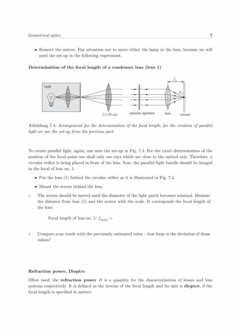
Determination of the focal length of a condenser lens (lens 1)
fL1
F2
f = 10 cm
bulb
annular aperture lens screen
Abbildung 7.4: Arrangement for the determination of the focal length; for the creation of parallel
light we use the set-up from the previous part.
To create parallel light, again, one uses the set-up in Fig. 7.3. For the exact determination of the
position of the focal point one shall only use rays which are close to the optical axis. Therefore, a
circular orifice is being placed in front of the lens. Now, the parallel light bundle should be imaged
in the focal of lens no. 1.
• Put the lens (1) behind the circular orifice as it is illustrated in Fig. 7.4.
• Mount the screen behind the lens.
� The screen should be moved until the diameter of the light patch becomes minimal. Measure
the distance from lens (1) and the screen with the scale. It corresponds the focal length of
the lens:
Focal length of lens no. 1: f lens1 =
� Compare your result with the previously estimated value – how large is the deviation of those
values?
Refraction power, Dioptre
Often used, the refraction power D is a quantity for the characterization of lenses and lens
systems respectively. It is defined as the inverse of the focal length and its unit is dioptre, if the
focal length is specified in meters:
8 Geometrical optics
Refraction power D =1
f; Unit: 1 Dioptre = 1 dpt = 1/m.
Remember: The bigger the refraction power the smaller the focal length of a lens.
� State the refraction power of lens no. 1 in dioptres.
D =
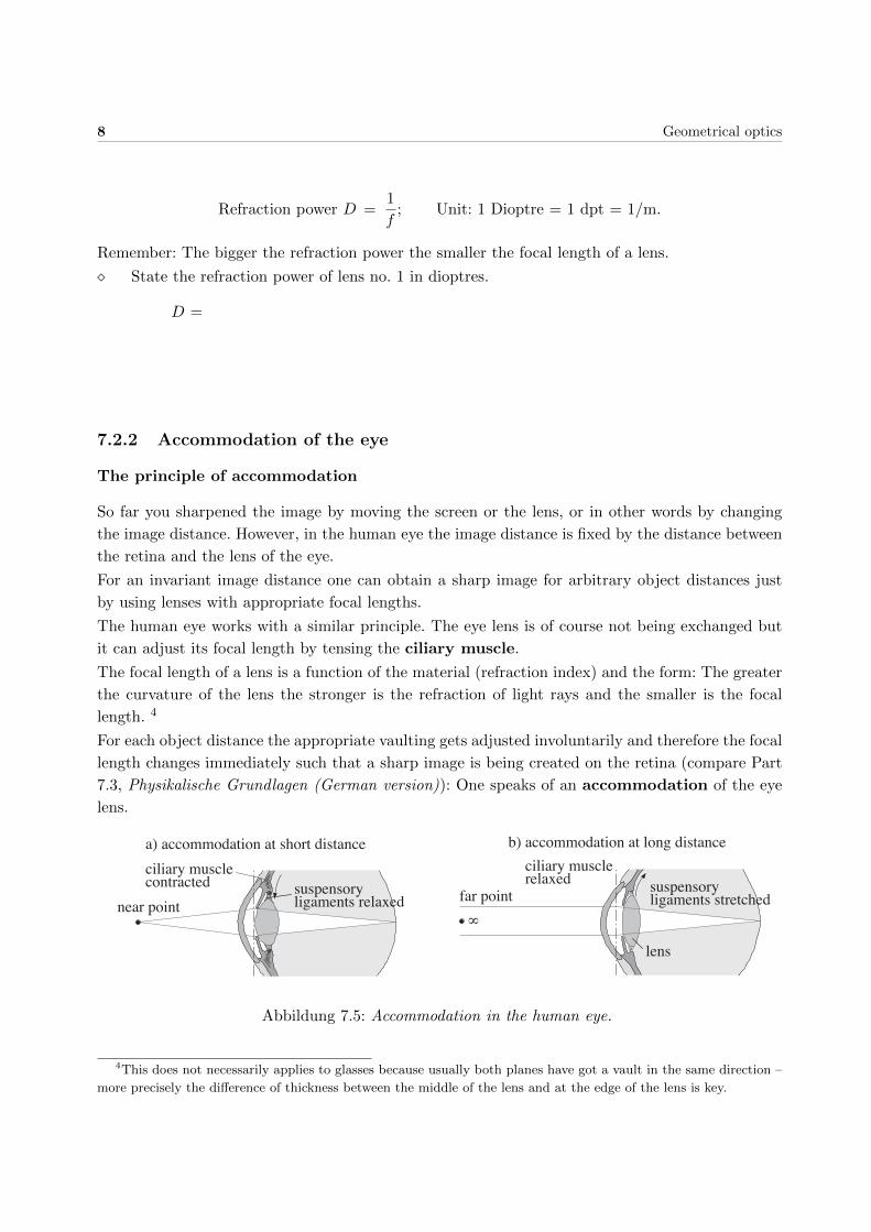
7.2.2 Accommodation of the eye
The principle of accommodation
So far you sharpened the image by moving the screen or the lens, or in other words by changing
the image distance. However, in the human eye the image distance is fixed by the distance between
the retina and the lens of the eye.
For an invariant image distance one can obtain a sharp image for arbitrary object distances just
by using lenses with appropriate focal lengths.
The human eye works with a similar principle. The eye lens is of course not being exchanged but
it can adjust its focal length by tensing the ciliary muscle.
The focal length of a lens is a function of the material (refraction index) and the form: The greater
the curvature of the lens the stronger is the refraction of light rays and the smaller is the focal
length. 4
For each object distance the appropriate vaulting gets adjusted involuntarily and therefore the focal
length changes immediately such that a sharp image is being created on the retina (compare Part
7.3, Physikalische Grundlagen (German version)): One speaks of an accommodation of the eye
lens.
∞
suspensory ligaments relaxed
lens
far point
ciliary musclecontracted
a) accommodation at short distance b) accommodation at long distance
near pointsuspensory ligaments stretched
ciliary musclerelaxed
Abbildung 7.5: Accommodation in the human eye.
4This does not necessarily applies to glasses because usually both planes have got a vault in the same direction –
more precisely the difference of thickness between the middle of the lens and at the edge of the lens is key.

Geometrical optics 9
You can review the connection between vault and focal length in cooperation with the assistant
at the magnet board in the lab. The lamp emits a bundle of parallel light rays. When passing the
different lenses the light rays are being distracted from their previous direction, in fact this effect
becomes stronger with larger curvatures of the lens.
The eye model
In the second experimental part you can investigate in the principles of image creation in the human
eye and the consequences of ametropia (defective vision).
air: n = 1n' = 1.3365
cornea
lens: n = 1.358
retina
Abbildung 7.6: Schematic illustration of the eye as an imaging system (compare Fig. 7.1).
Fig. 7.6 once again shows the important parts of the eye for image creation and the corresponding
components in the used eye model. The eye lens, which is capable of accommodation, is being
realized in the model by two foils in between where one can pour in water with a syringe (Fig. 7.7).
The filling quantity defines the vault of the lens faces and therefore the focal length. 5 This variation
happens continuously as it does in the real eye. The indication in millimetres on the syringe serves
as a gauge for the filling quantity of the lens.
For the experiment the following equipment is available:
– An optical bench with sliders and a scale,
– an illuminated object,
– the eye model with curved entry faces, a lens with variable focal length and a matt screen
(retina) (Fig. 7.7),
– two eyeglass lenses with indicated refraction powers: -0.5 dpt and +1 dpt.
5The variation of the filling quantity does not have any anatomical correspondence. The actual accommodation
mechanism is not realizable due to technical issues. However, in both cases an adjustment of the refraction power is
being realized by varying the curvature of the lens faces.

10 Geometrical optics
The whole eye model is flexible, the length of the eye can be adjusted by moving the matt screen:
Position 1 emmetropic (normal) eye,
Position 2 hyperopic (farsighted) eye ,
Position 3 myopic (shortsighted) eye.
BeG
BrL M (“retina”)
Abbildung 7.7: Set-up of the eye model. The markers function as distance measurements.
Here imply:
G = Object Be = Illumination
M = Matt screen Br = Eyeglass lens
L = Lens with continuously variable focal length
The accommodation range of the eye is limited by the maximal and minimal filling quantity of
30 ml and 60 ml respectively. The corresponding vaulting and refraction power of the lens defines
the furthermost and the nearest point for which one obtains a sharp image on the matt screen
(retina): They are called near point and far point respectively.
Please note:Do not touch the eye lens since it might get soiled or damaged!
� Observe the vaulting of the eye lens for the filling quantities stated above. Note your observa-
tions in the following table (use + and - to indicate large and small respectively). State in the
following columns whether this vaulting belongs to a large (+) or small (-) refraction power
and focal length respectively. Also state whether the position of the syringe corresponds to
the near– or far point.
Syringe position Vaulting Refraction power Focal length Near–/Far point
30 ml
60 ml
Geometrical optics 11
Accommodation of the emmetropic (normalsighted) eye
An emmetropic eye is given, if the eye sees sharp in very large distance while being in the not–
accommodated state (minimum filling quantity). This requirement is fulfilled for the eye model
when you hook in the matt screen at the position which is denoted by (1).
• Choose position (1) for the matt screen.
• Choose the object distance g to be about 28 – 30 cm.
• Adjust the amount of water in the lens until the image on the matt screen appears sharp.

12 Geometrical optics
� Note the syringe position. Measure the corresponding image distance bnormal and calculate
the focal length.
Syringe position [ml]:
Image distance bnormal =
Focal length (arises from the projection equation Eqn. (??) in Part 7.3, Physikalische
Grundlagen (German version)):
f = b·gb+g =
� With the focal length, calculate the refraction power of the lens in dioptres with same syringe
position (units!).
Refraction power D =
� Determine the minimal and maximal object distance for which you get a sharp image on the
matt screen by varying the amount of water in the lens, i.e. determine the near– and far point
of the eye.
Choose the syringe positions to be the following: 30 ml and 60 ml.
Near point at gnear =
Far point at gfar =
� Calculate the focal lengths and refraction powers for the near– and far point respectively.
Near point: fnear = → Dnah =
Far point: f far = → Dfern =
� Thus, how large is the accommodation width and the accommodation range of the normal
(emmetropic) eye?
Accommodation width = Difference of maximal and minimal refraction power [dpt]:
Accommodation range = Section between near– and far point, in which the object can
be imaged sharply:

Geometrical optics 13
Farsightedness (hyperopia)
The farsighted (hyperope) eye is, compared to the normal one, too short. Therefore, the matt screen
has to be locked into position (2).
� Move the matt screen to pos. (2) und measure the new image distance.
Image distance bfar =
� Again, determine the near– and far point of the eye for the same accommodation width as
for the normal sighted eye, i.e. for the syringe positions of 30 ml and 60 ml.
Near point gnear =
Far point gfar =
Accommodation range =
� Choose the appropriate eyeglass lens to improve the situation. Note the dioptre number.
Now, i.e. with glasses, where does the near point lie? (Move the object closer to the eye,
until the image gets sharp.)
Refraction power of the eyeglass lens: Dglasses =
Near point with glasses gnear =
� Compare your results with the ones for the normal sighted eye with special focus on the
accommodation range. Why is it recommended for far sighted people to wear the glasses for
long distances too? (Mind that the filling quantity in the lens of the model represents the
tension of the ciliary muscle! It might be helpful to investigate the influence of the eyeglass
lens from before on the image for long distances.)
14 Geometrical optics
Shortsightedness (myopia)
The shortsighted (myope) eye is, compared to the normal sighted eye, too long. Hence, the corre-
sponding mark (3) for the matt screen is located farther behind.
� Move the matt screen to position (3) and measure the new image distance.
Image distance bnear =
� Again, determine the near– and far point of the eye for the same accommodation width as
for the normal sighted eye, i.e. for syringe positions of 30 ml and 60 ml.
Near point gnear =
Far point gfar =
Accommodation range =
� Choose the appropriate eyeglass lens to improve the situation. Note the dioptre number.
Now, i.e. with glasses, where does the near point lie? (Move the object further afar from the
eye until the image appears sharp again.)
Refraction power of the eyeglass lens: Dglasses =
Far point with glasses gfar =
� Compare your results with the ones for the normal sighted eye with special focus on the
accommodation range. What kind of problems could occur for a short sighted person when
he wants to observe objects which lie in great distance? What effect causes the eyeglass lens
in this particular case?

Geometrical optics 15
Near point of the own eye
You can determine the near point of your own eyes roughly by fixating an object with your sight
and bringing it closer to the eye such that you can barely see it sharply.
� Let someone else measure the distance from the object to your eye (carefully!). Wearer of
glasses should perform the experiment with and without glasses and compare the results.
Near point right eye:
without glasses gnear = with glasses gnear =
Near point left eye:
without glasses gnear = with glasses gnear =
7.3 Physics behind this experiment
This section only exists in the German version of the lab manuals.