6x8 MATRIX LED DRIVER - ISSI · 6x8 MATRIX LED DRIVER Integrated Silicon Solution, Inc. – 1 Rev....
13
6x8 MATRIX LED DRIVER Integrated Silicon Solution, Inc. – www.issi.com 1 Rev. C, 03/22/2017 DESCRIPTION The IS32FL3738 is an automotive grade general purpose 6×8 LEDs matrix driver with 1/12 cycle rate. The device can be programmed via an I2C compatible interface. Each LED can be dimmed individually with 8-bit × 4 PWM data which allowing 512 steps of linear dimming. IS32FL3738 features 3 Auto Breathing Modes which are noted as ABM-1, ABM-2 and ABM-3. For each Auto Breathing Mode, there are 4 timing characters which include current rising / holding / falling / off time and 3 loop characters which include Loop-Beginning / Loop-Ending / Loop-Times. Every LED can be configured to be any Auto Breathing Mode or No-Breathing Mode individually. FEATURES Up to 48 LEDs (6×8) in dot matrix Programmable 6×8 (16 RGBs) matrix size with de-ghost function Selectable 3 Auto Breath Modes for each dot Auto Breath Loop Features interrupt pin inform MCU Auto Breath Loop completed Auto Breath offers 128 steps gamma current, interrupt and state look up registers 256 steps Global Current Setting Individual 512 PWM control steps Individual Auto Breath Mode select Individual open and short error detect function QUICK START Figure 1: Photo of IS32FL3738 Evaluation Board (V01A board with 12V DC input please refer to AppendixⅠ) RECOMMENDED EQUIPMENT 5.0V, 2A Micro USB Arduino IDE, www.arduino.cc/en/Main/Software Arduino code download from ISSI website ABSOLUTE MAXIMUM RATINGS ≤ 5.5V Micro USB DC power supply Caution: Do not exceed the conditions listed above, otherwise the board will be damaged. PROCEDURE The IS32FL3738 evaluation board is fully assembled, tested and comes programmed with evaluation software. Follow the steps listed below to verify board operation. Caution: Do not turn on the power supply until all connections are completed. 1) Connect the 5VDC USB power to the Micro USB. 2) Press K1 to cycle through a display mode. EVALUATION BOARD OPERATION The IS32FL3738 evaluation board drives16 RGB LEDs located underneath the light dispersing filter. Every press of the K1 switch will cycle through one of the 8 pre-programmed lighting sequences below: 1) White LED 2) Rainbow bar 3) Red color breath 4) Green color breath 5) Blue color breath 6) Pink color breath 7) Yellow color breath 8) Cyan color breath Note: IS32FL3738 solely controls the FxLED function on the evaluation board. ORDERING INFORMATION Part No. Temperature Range Package IS32FL3738-ZLA3-EB -40°C to +125°C (Automotive) eTSSOP-28, Lead-free Table 1: Ordering Information For pricing, delivery, and ordering information, please contacts ISSI’s analog marketing team at [email protected] or (408) 969-6600.
Transcript of 6x8 MATRIX LED DRIVER - ISSI · 6x8 MATRIX LED DRIVER Integrated Silicon Solution, Inc. – 1 Rev....

6x8 MATRIX LED DRIVER
Integrated Silicon Solution, Inc. – www.issi.com 1 Rev. C, 03/22/2017
DESCRIPTION
The IS32FL3738 is an automotive grade general purpose 6×8 LEDs matrix driver with 1/12 cycle rate. The device can be programmed via an I2C compatible interface. Each LED can be dimmed individually with 8-bit × 4 PWM data which allowing 512 steps of linear dimming.
IS32FL3738 features 3 Auto Breathing Modes which are noted as ABM-1, ABM-2 and ABM-3. For each Auto Breathing Mode, there are 4 timing characters which include current rising / holding / falling / off time and 3 loop characters which include Loop-Beginning / Loop-Ending / Loop-Times. Every LED can be configured to be any Auto Breathing Mode or No-Breathing Mode individually.
FEATURES
Up to 48 LEDs (6×8) in dot matrix Programmable 6×8 (16 RGBs) matrix size with
de-ghost function Selectable 3 Auto Breath Modes for each dot Auto Breath Loop Features interrupt pin inform
MCU Auto Breath Loop completed Auto Breath offers 128 steps gamma current,
interrupt and state look up registers 256 steps Global Current Setting Individual 512 PWM control steps Individual Auto Breath Mode select Individual open and short error detect function
QUICK START
Figure 1: Photo of IS32FL3738 Evaluation Board
(V01A board with 12V DC input please refer to AppendixⅠ)
RECOMMENDED EQUIPMENT
5.0V, 2A Micro USB Arduino IDE, www.arduino.cc/en/Main/Software Arduino code download from ISSI website
ABSOLUTE MAXIMUM RATINGS
≤ 5.5V Micro USB DC power supply
Caution: Do not exceed the conditions listed above, otherwise the board will be damaged.
PROCEDURE
The IS32FL3738 evaluation board is fully assembled, tested and comes programmed with evaluation software. Follow the steps listed below to verify board operation.
Caution: Do not turn on the power supply until all connections are completed.
1) Connect the 5VDC USB power to the Micro USB. 2) Press K1 to cycle through a display mode. EVALUATION BOARD OPERATION
The IS32FL3738 evaluation board drives16 RGB LEDs located underneath the light dispersing filter. Every press of the K1 switch will cycle through one of the 8 pre-programmed lighting sequences below:
1) White LED 2) Rainbow bar 3) Red color breath 4) Green color breath 5) Blue color breath 6) Pink color breath 7) Yellow color breath 8) Cyan color breath
Note: IS32FL3738 solely controls the FxLED function on the evaluation board.
ORDERING INFORMATION
Part No. Temperature Range Package
IS32FL3738-ZLA3-EB -40°C to +125°C (Automotive) eTSSOP-28, Lead-free
Table 1: Ordering Information
For pricing, delivery, and ordering information, please contacts ISSI’s analog marketing team at [email protected] or (408) 969-6600.

6x8 MATRIX LED DRIVER
Integrated Silicon Solution, Inc. – www.issi.com 2 Rev. C, 03/22/2017
SOFTWARE CONTROL
The evaluation board comes with an Arduino compatible microcontroller circuit preloaded with IS32FL3738 demonstration firmware, called a sketch. This allows the functionality of the IS32FL3738 to be verified before starting firmware development.
The Arduino hardware consists of an Atmel microcontroller with a bootloader allowing quick firmware updates. First download the latest Arduino Integrated Development Environment IDE (1.6.12 or greater) from www.arduino.cc/en/Main/Software. Then download the latest IS32FL3738 firmware (sketch) from the ISSI website www.issi.com/US/product-analog-automotive.shtml. When using the Arduino environment, please select Genuino UNO as shown below, then select the serial port. Follow the standard procedure to upload the latest IS32FL3738 firmware into the Arduino; then use the IDE to modify it. There is no additional software required to run the eval board.
EXT-SOFTWARE CONTROL
The IS32FL3738 can also be driven by an external IIC source.
Follow the steps below to configure the eval board for external control.
1) Open the two pins of J7 on the right side, to disable the onboard Arduino and enable external control (the SDA SCL and SDB become high impedance).
2) Default VIO is 5V, if you use a 3.3V IO, connect 3.3V to VIO pin in J7.
3) Connect SDB to VIO or high level IO 4) Connect external IIC to the IIC pins of J7 5) Start external IIC control.
Please refer to the datasheet to get more information about IS32FL3738

6x8 MATRIX LED DRIVER
Integrated Silicon Solution, Inc. – www.issi.com 3 Rev. C, 03/22/2017
Figure 2: IS32FL3738 Application Schematic
PE6/INT6/AIN01
UVCC2
D-3
D+4
UGND5
UCAP6
VBUS7
PB0/SS/PCINT08
PB1/SCLK/PCINT19
PB2/PDI/MOSI/PCINT2 10PB3/PDO/MISO/PCINT3
11PB7/OC0A/OC1C/RTS 12
RESET13
VCC14
GND15
XTAL216
XTAL117
PD0/OC0B/SCL/INT018
PD1/SDA/INT1 19PD2/RXD1/INT2
20PD3/TXD1/INT3 21
PD5/XCK1/CTS22
GND23
AVCC24
PD4/ICP1/ADC825
PD6/T1/OC4D/ADC9 26PD7/T0/OC4D/ADC10
27PB4/PCINT4/ADC11 28
PB5/PCINT5/OC1A/OC4B/ADC1229
PB6/PCINT6/OC1B/OC4B/ADC13 30PC6/OC3A/OC4A
31
PC7/ICP3/CLK0/OC4A32
PE2/HWB33
VCC34
GND35
PF7/ADC7/TDI 36PF6/ADC6/TDO
37PF5/ADC5/TMS
38PF4/ADC4/TCK
39PF1/ADC1
40PF0/ADC0
41
AREF42
GND43
AVCC44
U1
ATMEGA32U4
5V
10K
R1
100n
C11
100n
C10
GND
13
4 2
TS42
SMD-KEY-5P
GND
RD-RD+
Y1
16M
22pF
C12
22pF
C13
GND
1uF
C5
100nF
C6
GND
OSC_OUTOSC_IN
1uF
C7AVCC
1K
R7
1K
R8
RX
L
TX
ON 1K
R6
1K
R5
10KR4
UCAP
AREF
GND
5V
RX
Blue
Green
RXLED
IO13
TXLED
HWB
VUSB
A5
A4
A0
A1
A2
A3
D1/TX
D0/RX
D2/SDA
D3/SCL
SDB
D5
D6
KEY
IO12
IO11
IO10
IO9
IO8
MOSI
MISO
SCK
VCC1
USB_DM2
USB_DP3
NC4
GND5
J3
USB_Micro
MSMF050-2
F1VUSB
22RRP3B
22RRP3A
D-D+
RD+
RD-
CG0603MLC-05E
Z2 Z1
GND
1uFC14100nF
C9
10K
R2
USB_VCC
GND
11
33
55
22
44
66
J4
ICSP
MISO
SCK
RESET
5V
MOSI
GND
3 2
1
T1
FDN340P
VUSB VIN 5V
IN3
GN
D1
OUT2
U2
NCP1117-510KR9
100nF
C1
1uF
C3
100nF
C2
5V
GND
VIN
IN1
GND2
ON/OFF3
OUT4
NC/FB5
U4
LP2985-33DBVR
5V
GND
1uF
C4
3.3V
GND
3V3 REG5V REG5V SELECTOR(USB)
23
1
T2
PMV48XP
5V
11
22
33
44
55
66
77
88
99
1010
1111
1212
1313
1414
1515
1616
1717
J51 1
22
33
4 4
55
66
7 7
88
99
1010
1111
1212
1313
1414
1515
1616
1717
J6MOSIRXLED/SSD1/TXD0/RXRESETGNDD2/SDAD3/SCLD4D5D6D7IO8IO9IO10IO11IO12
SCKMISOVINGNDRESET5V
A5A4A3A2A1A0AREF3.3VIO13
GND
OUTIN
TX
RESET
D2
CD1206-S01575
Arduino
IS32FL3738
CS81
REST2
AVCC3
VIO4
SYNC5
SDA6
SCL7
ADDR8
INTB9
SDB10
GND11
SW112
SW213
PGND14
SW315
SW416
SW517
PGND18
SW619
CS120
CS221
PVCC22
CS323
CS424
CS525
CS626
PVCC27
CS728
U5
IS3738
0.1uF
C205V
5V
5V
R204.7K
R214.7K
R22100K
VIO
R24100K
R2320K
SDA
SCL
INTB
SDB
SYNC
REST
R25100K
GND
0.1uFC23
GND
VIO
CS1
CS2
CS3
CS4
CS5
CS6
CS7
CS8
SW1
SW2
SW3
SW4
SW5
SW6
0.1uF
C21
0.1uF
C22
ADDR
R26
1k
5V
K1MODE
GND
R2710K
0.1uFC24
5V
GND
KEY
R28
0R
R29100K
VCC
GND
A5
JP1
GND
GND
GND
MH2029-300Y
L2
11
22
33
44
55
66
77
88
99
1010
1111
1212
1313
J7
GNDGND
INTBSYNCADDR
VIO
SDBGND
SCLSDA5V_J7
D3
DFL240
A5A5-2
A5-2
1uFC261uFC25
GND
GND
5V
LED Matrix
LD1 LD2 LD3 LD4 LD5 LD6 LD14 LD15LD7 LD8 LD12 LD13LD9 LD10 LD11 LD16
CS1CS2CS3CS4CS5CS6CS7CS8
SW1SW2SW3SW4SW5SW6

6x8 MATRIX LED DRIVER
Integrated Silicon Solution, Inc. – www.issi.com 4 Rev. C, 03/22/2017
BILL OF MATERIALS - Arduino
Name Symbol Description Qty Supplier Part No.
MCU U1 Microcontroller 1 ATM ATMEGA32U4
LDO U2 Reduced voltage 1 ON NCP1117-5
LDO U4 Reduced voltage 1 TI LP2985-33DBVR
Triode T1 FET 1 FAIRCHILD FDN340P
Triode T2 FET 1 NXP PMV48XP
Crystal Y1 Crystal, 16MHz 1 Risym 3225 16MHz
Button K1 Button SMD 1 MT SMD-KEY-5P
LED ON,TX,RX LED, SMD Blue 3 EVERLIGHT 0603
LED L LED, SMD Green 1 EVERLIGHT 0603
F1 F1 SMD Fuse 1 MF MSMF050-2
Beads L2 Beads 1 BOURNS MH2029-300Y
Diode D2 Diode, SMD 1 BOURNS CD1206-S01575
Varistor Z1,Z2 Varistor 2 BOURNS CG0603MLC-05E
Resistor RP3A,PR3B RES,22R,1/16W,±5%,SMD 2 Yageo RC0603JR-0722RL
Resistor R5,R6,R7,R8 RES,1k,1/16W,±5%,SMD 4 Yageo RC0603JR-071KL
Resistor R1,R2,R4,R9 RES,10k,1/16W,±5%,SMD 4 Yageo RC0603JR-0710KL
Capacitor C12,C13 CAP,22pF,16V,±20%,SMD 2 Yageo CC0603KKX7R9BB22
Capacitor C1,C2,C6,
C9,C10,C11 CAP,100nF,16V,±20%,SMD 6 Yageo CC0603KKX7R9BB101
Capacitor C3,C4,C5,C7,C14 CAP,1µF,16V, ±20%,SMD 4 Yageo CC0603KKX7R9BB105
BILL OF MATERIALS – IS32FL3738
Name Symbol Description Qty Supplier Part No.
LED Driver U5 Matrix LED Driver 1 ISSI IS32FL3738
RGB LED LD1~LD16 RGB LED, SMD 16 ROHM SMLV56RGB1W1
Diode D3 Diode, SMD 1 DIODES DFLS240
Resistor R20,R21 RES,4.7k,1/16W,±5%,SMD 2 Yageo RC0603JR-074K7L
Resistor R22,R24,R25,R29 RES,100k,1/16W,±5%,SMD 4 Yageo RC0603JR-07100KL
Resistor R23 RES,20k,1/16W,±5%,SMD 1 Yageo RC0603JR-0720KL
Resistor R26 RES,1k,1/16W,±5%,SMD 1 Yageo RC0603JR-071KL
Resistor R27 RES,10k,1/16W,±5%,SMD 1 Yageo RC0603JR-0710KL
Resistor R28 RES,0k,1/16W,±5%,SMD 1 Yageo RC0603JR-070KL
Capacitor C20,C21,C22,C23,C24 CAP,0.1µF,16V,±20%,SMD 5 Yageo CC0603KKX7R9BB104
Capacitor C25,C26 CAP,1µF,16V,±20%,SMD 2 Yageo CC0603KKX7R9BB105
Button K1(Bottom) Button 1
Bill of Materials, refer to Figure 1 above.

6x8 MATRIX LED DRIVER
Integrated Silicon Solution, Inc. – www.issi.com 5 Rev. C, 03/22/2017
2
2 3
32
2 2
212345678910111214 13
97654321 8 10 11 12 13
222
221
1234567891011121314151617
1234567891011121314151617
1
1
0
0
0
0
2 3
1 0
Figure 3: Board Component Placement Guide - Top Layer
0
0
0
0
0
0
0
0
0
0
0 0
0
0
0
0
0
0
0
0
0
0
0
0 0
00 0 00 0 000 0 000 0 000 0 000 0 000 0 000 0 000 0 000 0 000 0 000 0 000 0 000 0 000 0 000 0 000 0
00 0 000 0 000 0 000 0 000 0 000 0 000 0 000 0 000 0 000 0 000 0 000 0 000 0 000 0 000 0 000 00
2
2 3
32
2 2
212345678910111214 13
1 2
97654321 8 10 11 12 13
12
1 2
1 2
1 2
1 2
1 2
1
2
1
2
1 2
1 2
29
12
222
221
1
2
5
4
3
1234567891011121314151617
1234567891011121314151617
1
2
4
3
1
1
0
0
0
0
1
2
1 2
3
1 2
3 1
2
1
2
1
2
1
2
1212
1
2
1
2
12
0
2
12
12
1
12
1
2
12
2 3
1 0
Figure 4: Board PCB Layout - Top Layer

6x8 MATRIX LED DRIVER
Integrated Silicon Solution, Inc. – www.issi.com 6 Rev. C, 03/22/2017
2
2 3
32
2 2
212345678910111214 13
97654321 8 10 11 12 13
222
221
1234567891011121314151617
1234567891011121314151617
1
1
0
0
0
0
2 3
1 0
Figure 5: Board Component Placement Guide - Bottom Layer
2
2 3
32
2 2
212345678910111214 13
121 2
97654321 8 10 11 12 13
1 2
1 2
222
221
1234567891011121314151617
1234567891011121314151617
121 2
1
1
0
0
0
0
4
5
1
2
3
12 1 2
1 2
2
1
1 2
1
2
12
2
1
12
4
3 2 1
1 2
1
2
12
1 2
1
2
12
2 3
1 012
Figure 6: Board PCB Layout - Bottom Layer
Copyright © 2017 Integrated Silicon Solution, Inc. All rights reserved. ISSI reserves the right to make changes to this specification and its products at any time without notice. ISSI assumes no liability arising out of the application or use of any information, products or services described herein. Customers are advised to obtain the latest version of this device specification before relying on any published information and before placing orders for products. Integrated Silicon Solution, Inc. does not recommend the use of any of its products in life support applications where the failure or malfunction of the product can reasonably be expected to cause failure of the life support system or to significantly affect its safety or effectiveness. Products are not authorized for use in such applications unless Integrated Silicon Solution, Inc. receives written assurance to its satisfaction, that: a.) the risk of injury or damage has been minimized; b.) the user assume all such risks; and c.) potential liability of Integrated Silicon Solution, Inc is adequately protected under the circumstances

6x8 MATRIX LED DRIVER
Integrated Silicon Solution, Inc. – www.issi.com 7 Rev. C, 03/22/2017
REVISION HISTORY
Revision Detail Information Date
A Initial release 2016.09.18
B 1. Deleted 12V, 1A power supply. 2. Update schematic and PCB. 3. Update bill of materials
2016.11.04
C Correct the PWM level to 512 levels, please check datasheet for more information. 2017.03.22
6x8 MATRIX LED DRIVER
Integrated Silicon Solution, Inc. – www.issi.com 8 Rev. C, 03/22/2017
APPENDIX Ⅰ: V01A GUIDE
QUICK START
Figure 7: Photo of IS32FL3738 Evaluation Board
RECOMMENDED EQUIPMENT V01A
5.0V, 2A Micro USB or 12V, 1A power supply
ABSOLUTE MAXIMUM RATINGS V01A
≤ 17V DC power supply ≤ 5.5V Micro USB DC power supply
Caution: Do not exceed the conditions listed above, otherwise the board will be damaged.
PROCEDURE V01A
The IS32FL3738 evaluation board is fully assembled and tested. Follow the steps listed below to verify board operation.
Caution: Do not turn on the power supply until all connections are completed.
1) Connect the 12VDC power to the connector or 5VDC USB power to the Micro USB.
2) Turn on the power supply, pay attention to the supply current. If the current exceeds 1A, please check for circuit fault.
EVALUATION BOARD OPERATION V01A
The IS32FL3738 evaluation board has three animation display modes. Press K1 to switch configurations.
1) White LED
2) Rainbow bar 3) Red LED breath 4) Green LED breath 5) Blue LED breath 6) Red and blue LED breath 7) Red and green LED breath 8) Blue and green LED breath
Note: IS32FL3738 solely controls the FxLED function on the evaluation board.
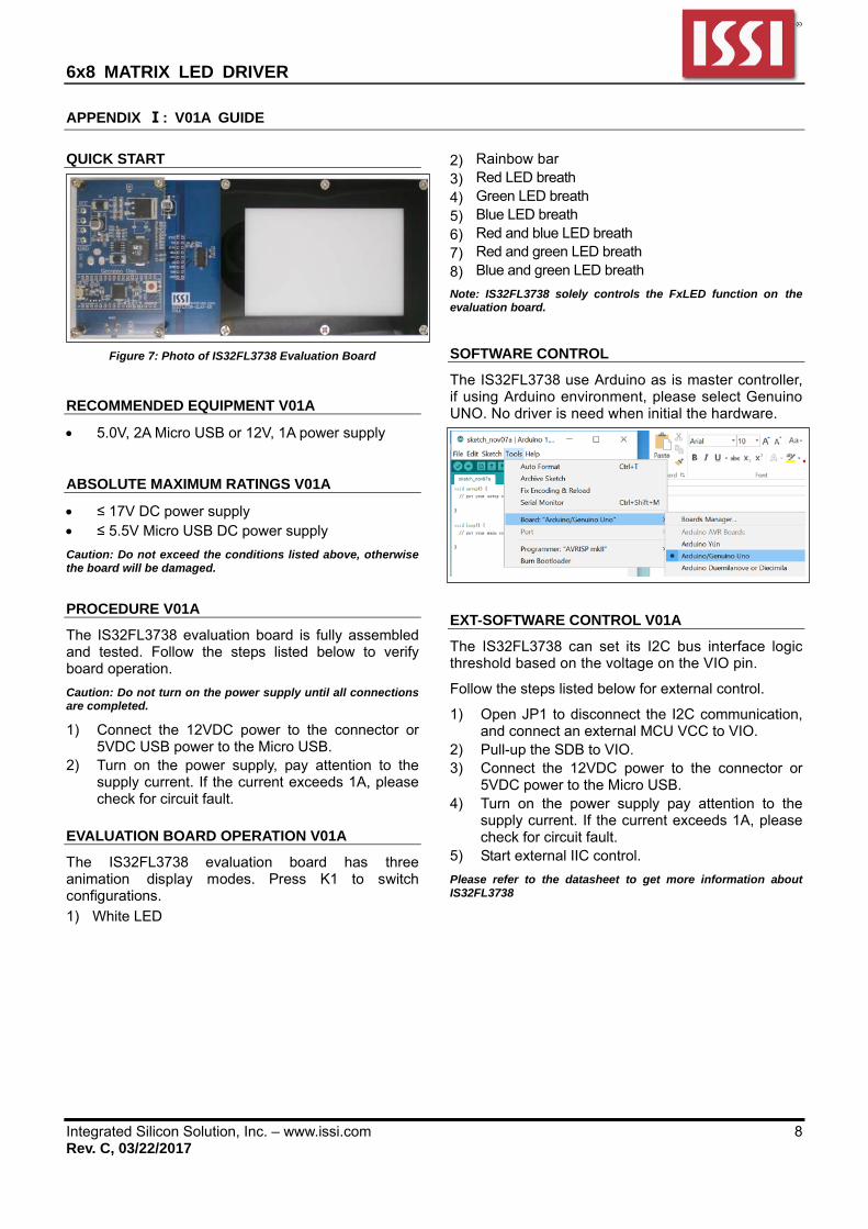
SOFTWARE CONTROL
The IS32FL3738 use Arduino as is master controller, if using Arduino environment, please select Genuino UNO. No driver is need when initial the hardware.
EXT-SOFTWARE CONTROL V01A
The IS32FL3738 can set its I2C bus interface logic threshold based on the voltage on the VIO pin.
Follow the steps listed below for external control.
1) Open JP1 to disconnect the I2C communication, and connect an external MCU VCC to VIO.
2) Pull-up the SDB to VIO. 3) Connect the 12VDC power to the connector or
5VDC power to the Micro USB. 4) Turn on the power supply pay attention to the
supply current. If the current exceeds 1A, please check for circuit fault.
5) Start external IIC control.
Please refer to the datasheet to get more information about IS32FL3738

6x8 MATRIX LED DRIVER
Integrated Silicon Solution, Inc. – www.issi.com 9 Rev. C, 03/22/2017
Figure 8: IS32FL3738 Application Schematic: V01A
PE6/INT6/AIN0 1
UVCC2
D-3
D+4
UGND5
UCAP6
VBUS 7
PB0/SS/PCINT08
PB1/SCLK/PCINT1 9PB2/PDI/MOSI/PCINT2 10
PB3/PDO/MISO/PCINT3 11PB7/OC0A/OC1C/RTS 12
RESET13
VCC14
GND15
XTAL216
XTAL117
PD0/OC0B/SCL/INT0 18PD1/SDA/INT1 19
PD2/RXD1/INT2 20PD3/TXD1/INT3 21
PD5/XCK1/CTS22
GND23
AVCC24
PD4/ICP1/ADC8 25PD6/T1/OC4D/ADC9 26
PD7/T0/OC4D/ADC10 27PB4/PCINT4/ADC11 28
PB5/PCINT5/OC1A/OC4B/ADC12 29PB6/PCINT6/OC1B/OC4B/ADC13 30
PC6/OC3A/OC4A 31
PC7/ICP3/CLK0/OC4A32
PE2/HWB33
VCC34
GND35
PF7/ADC7/TDI 36PF6/ADC6/TDO 37PF5/ADC5/TMS 38PF4/ADC4/TCK 39
PF1/ADC1 40PF0/ADC0 41
AREF42
GND43
AVCC44
U1
ATMEGA32U4
5V
MH2029-300Y
L2
10K
R1
100n
C11
100n
C10
GND
13
4 2
K1
SMD-KEY-5P
GND
RD-RD+
Y1
16M
22pF
C12
22pF
C13
GND
1uF
C5
100nF
C6
GND
OSC_OUTOSC_IN
1uF
C7AVCC
1K
R7
1K
R8
RX
L
TX
ON 1K
R6
1K
R5
10KR4
UCAP
AREF
GND
5V
RX
Blue
Green
RXLED
IO13
TXLED
HWB
VUSB
A5
A4
A0
A1
A2
A3
D1/TX
D0/RX
D2/SDA
D3/SCL
SDB
D5
D6
KEY
IO12
IO11
IO10
IO9
IO8
MOSI
MISO
SCK
VCC1
USB_DM2
USB_DP3
NC4
GND5
USB_Micro
MSMF050-2
F1VUSB
22R
R3
22R
R10
D-D+RD+
RD-
CG0603MLC-05E
Z2 Z1
GND
22uFC14100nF
C9
10K
R2
USB_VCC
GND
11
33
55
2 2
4 4
6 6
ICSPMISO
SCK
RESET
5V
MOSI
GND
3 2
1
T1
FDN340P
VUSB VIN 5V
IN3
GN
D1
OUT 2
U2
NCP1117-510KR9
100nF
C1
22uF
C3
100nF
C2
5V
GND
VIN
IN1
GND2ON/OFF3
OUT 4
NC/FB 5
U4
LP2985-33DBVR
5V
GND
1uF
C4
3.3V
GND
3V3 REG5V REG5V SELECTOR(USB)
23
1
T2
PMV48XP
5V
11
22
33
44
55
66
77
88
99
1010
1111
1212
1313
1414
1515
1616
1717
J51 1
2 2
3 3
44
5 5
6 6
7 7
8 8
9 9
10 10
11 11
1212
13 13
14 14
15 15
16 16
17 17
J6MOSIRXLED/SSD1/TXD0/RXRESETGNDD2/SDAD3/SCLD4D5D6D7IO8IO9IO10IO11IO12
SCKMISOVINGNDRESET5V
A5A4A3A2A1A0AREF3.3VIO13
GND
OUTIN
TX
RESET
D2
CD1206-S01575
Arduino
IS32FL3738
CS8 1
REST2
AVCC3
VIO 4
SYNC5
SDA6
SCL7
ADDR8
INTB9
SDB10
GND11
SW1 12SW2 13
PGND14
SW3 15SW4 16SW5 17
PGND18
SW6 19
CS1 20CS2 21
PVCC22
CS3 23CS4 24CS5 25CS6 26
PVCC27
CS7 28
U2
IS3738
0.1uFC14
5V
5V
5V
R64.7K
R74.7K
R9100K
GND
GND
GND
VIO
R10100K
R1420K
SDA
SCL
INTB
SDB
SYNC
REST
R8100K
GND
0.1uFC11
GND
VIO
CS1
CS2
CS3
CS4
CS5
CS6
CS7
CS8
SW1
SW2
SW3
SW4
SW5
SW6
0.1uFC13
0.1uFC12
ADDR
GND5
RT 6
VIN 7
BS 8SW1
COMP3
FB4
EN2
Thermal Pad 9
U1
IS32PM3415
R5
200K
R3
100K
R451K
C7330pF
C6NC
C3
0.1uF
C2
4.7uF
C4
0.1uF
C9
10uF
EN
EN
D2
SS36
L1
22uH
C5NC
VOUT
SW
GND1GND2VCC3VCC4
*
*
D1
SS36C1
100uF/25V
C16
100uF/25V
R162K
R212K
GND
C15
1uF
VIN3 Vout 2
AD
J1
U3
LM317
R15
390R
R16120R
C8
100uF/25V
VOUT 5V
GNDGND
K1MODE
GND
R1110K
0.1uFC9
5V
GND
KEY
R12
0R
R13
NC
5V
3V
R1851K
R1751K
VCC
GND
A5
JP1
GND
LED Matrix
LD1 LD2 LD3 LD4 LD5 LD6 LD14 LD15LD7 LD8 LD12 LD13LD9 LD10 LD11 LD16
CS1CS2CS3CS4CS5CS6CS7CS8
SW1SW2SW3SW4SW5SW6

6x8 MATRIX LED DRIVER
Integrated Silicon Solution, Inc. – www.issi.com 10 Rev. C, 03/22/2017
BILL OF MATERIALS (EVB Part)
Name Symbol Description Qty Supplier Part No.
Buck Chip U1 Buck Chip 1 ISSI IS32PM3415
LED Driver U2 Matrix LED Driver 1 ISSI IS32FL3738
LDO U3 Reduced voltage 1 ST LM317D2T
Diode LD1~LD16 RGB LED, SMD 16 ROHM SMLV56RGB1W1
Diode D1,D2 Diode, SMD 2 DIODES SS36
Resistor R5 RES,200k,1/16W,±5%,SMD 1 Yageo RC0603JR-07200KL
Resistor R3,R8,R9,R10 RES,100k,1/16W,±5%,SMD 4 Yageo RC0603JR-07100KL
Resistor R1 RES,62k,1/16W,±5%,SMD 1 Yageo RC0603JR-0762KL
Resistor R4,R17,R18 RES,51k,1/16W,±5%,SMD 3 Yageo RC0603JR-0751KL
Resistor R14 RES,20k,1/16W,±5%,SMD 1 Yageo RC0603JR-0720KL
Resistor R2 RES,12k,1/16W,±5%,SMD 1 Yageo RC0603JR-0712KL
Resistor R11 RES,10k,1/16W,±5%,SMD 1 Yageo RC0603JR-0710KL
Resistor R6,R7 RES,4.7k,1/16W,±5%,SMD 2 Yageo RC0603JR-074K7L
Resistor R15 RES,390R,1/16W,±5%,SMD 1 Yageo RC0603JR-07390RL
Resistor R16 RES,120R,1/16W,±5%,SMD 1 Yageo RC0603JR-07120RL
Resistor R12 RES,0R,1/16W,±5%,SMD 1 Yageo RC0603JR-070RL
Resistor R13 NC 1
Capacitor C15 CAP,1µF,16V,±20%,SMD 1 Yageo CC0603KKX7R9BB105
Capacitor C7 CAP,330pF,16V,±20%,SMD 1 Yageo CC0603KKX7R9BB331
Capacitor C4,12 CAP,4.7µF,16V, ±20%,SMD 2 Yageo CC0603KKX7R9BB476
Capacitor C6,C7 CAP,33pF,16V,±20%,SMD 2 Yageo CC0603KKX7R9BB330
Capacitor C8,C9,C10 CAP,0.1µF,16V,±20%,SMD 3 Yageo CC0603KKX7R9BB104
Button K1 Button SMD 1

6x8 MATRIX LED DRIVER
Integrated Silicon Solution, Inc. – www.issi.com 11 Rev. C, 03/22/2017
BILL OF MATERIALS (Genuino Uno Part)
Name Symbol Description Qty Supplier Part No.
MCU U1 Microcontroller 1 ATM ATMEGA32U4
LDO U2 Reduced voltage 1 ON NCP1117-5
LDO U4 Reduced voltage 1 TI LP2985-33DBVR
Triode T1 FET 1 FAIRCHILD FDN340P
Triode T2 FET 1 NXP PMV48XP
Crystal Y1 Crystal, 16MHz 1 Risym 3225 16MHz
Button K1 Button SMD 1 MT SMD-KEY-5P
LED ON,TX,RX LED, SMD Blue 3 EVERLIGHT 0603
LED L LED, SMD Greed 1 EVERLIGHT 0603
F1 F1 SMD Fuse 1 MF MSMF050-2
Beads L2 Beads 1 BOURNS RC0603JR-0712KL
Varistor Z1,Z2 Varistor 2 BOURNS CG0603MLC-05E
Resistor R3,R10 RES,22R,1/16W,±5%,SMD 2 Yageo RC0603JR-0722RL
Resistor R5,R6,R7,R8 RES,1k,1/16W,±5%,SMD 4 Yageo RC0603JR-071KL
Resistor R1,R2,R4 RES,10k,1/16W,±5%,SMD 3 Yageo RC0603JR-0710KL
Capacitor C12,C13 CAP,22pF,16V,±20%,SMD 2 Yageo CC0603KKX7R9BB22
Capacitor C1,C2,C6,
C9,C10,C11 CAP,100nF,16V,±20%,SMD 6 Yageo CC0603KKX7R9BB101
Capacitor C4,C5 CAP,1µF,16V, ±20%,SMD 2 Yageo CC0603KKX7R9BB105
Capacitor C3,C14 CAP,22µF,16V,±20%,SMD 2 Yageo CC0603KKX7R9BB226
Diode D2 Diode, SMD 1 BOURNS CD1206-S01575
Bill of Materials, refer to Figure 1 above.

6x8 MATRIX LED DRIVER
Integrated Silicon Solution, Inc. – www.issi.com 12 Rev. C, 03/22/2017
Figure 9: Board Component Placement Guide - Top Layer: V01A
Figure 10: Board PCB Layout - Top Layer: V01A

6x8 MATRIX LED DRIVER
Integrated Silicon Solution, Inc. – www.issi.com 13 Rev. C, 03/22/2017
Figure 11: Board Component Placement Guide - Bottom Layer: V01A
Figure 12: Board PCB Layout - Bottom Layer: V01A