6.Simple Shading Example -...
18
149 Chapter 6 6.Simple Shading Example Now that we’ve described the OpenGL Shading Language, let’s look at a simple example. In this example, we apply a brick pattern to an object. The brick pattern is calculated entirely within a fragment shader. If you’d prefer to skip ahead to the next chapter for a more in-depth discussion of the API that allows shaders to be defined and manipulated, feel free to do so. The shader for rendering a procedural brick pattern was the first interesting shader ever executed by the OpenGL Shading Language on programmable graphics hardware. It ran for the first time in March 2002, on the 3Dlabs Wildcat VP graphics accelerator. Dave Baldwin published the first GLSL brick fragment shader in a white paper that described the language des- tined to become the OpenGL Shading Language. His GLSL shader was based on a RenderMan shader by Darwyn Peachey that was published in the book, Texturing and Modeling: A Procedural Approach. Steve Koren and John Kessenich adapted Dave’s shader to get it working on real hardware for the first time, and it has subsequently undergone considerable refine- ment for inclusion in this book. This example, like most of the others in this book, consists of three essential components: the source code for the vertex shader, the source code for the fragment shader, and the application code that initializes and uses these shaders. This chapter focuses on the vertex and fragment shaders. The application code for using these shaders is discussed in Section 7.13, after the details of the OpenGL Shading Language API have been discussed. Rost.book Page 149 Tuesday, December 20, 2005 3:06 PM
Transcript of 6.Simple Shading Example -...

149
Chapter 6
6.Simple Shading Example
Now that we’ve described the OpenGL Shading Language, let’s look at a simple example. In this example, we apply a brick pattern to an object. The brick pattern is calculated entirely within a fragment shader. If you’d prefer to skip ahead to the next chapter for a more in-depth discussion of the API that allows shaders to be defined and manipulated, feel free to do so.
The shader for rendering a procedural brick pattern was the first interesting shader ever executed by the OpenGL Shading Language on programmable graphics hardware. It ran for the first time in March 2002, on the 3Dlabs Wildcat VP graphics accelerator. Dave Baldwin published the first GLSL brick fragment shader in a white paper that described the language des-tined to become the OpenGL Shading Language. His GLSL shader was based on a RenderMan shader by Darwyn Peachey that was published in the book, Texturing and Modeling: A Procedural Approach. Steve Koren and John Kessenich adapted Dave’s shader to get it working on real hardware for the first time, and it has subsequently undergone considerable refine-ment for inclusion in this book.
This example, like most of the others in this book, consists of three essential components: the source code for the vertex shader, the source code for the fragment shader, and the application code that initializes and uses these shaders. This chapter focuses on the vertex and fragment shaders. The application code for using these shaders is discussed in Section 7.13, after the details of the OpenGL Shading Language API have been discussed.
Rost.book Page 149 Tuesday, December 20, 2005 3:06 PM

150 Chapter 6: Simple Shading Example
With this first example, we take a little more time discussing the details in order to give you a better grasp of what’s going on. In examples later in the book, we focus mostly on the details that differ from previous examples.
6.1 Brick Shader Overview
One approach to writing shaders is to come up with a description of the effect that you’re trying to achieve and then decide which parts of the shader need to be implemented in the vertex shader, which need to be implemented in the fragment shader, and how the application will tie everything together.
In this example, we develop a shader that applies a computed brick pattern to all objects that are drawn. We don’t attempt the most realistic looking brick shader, but rather a fairly simple one that illustrates many of the con-cepts we introduced in the previous chapters. We don’t use textures for this brick pattern; the pattern itself is generated algorithmically. We can build a lot of flexibility into this shader by parameterizing the different aspects of our brick algorithm.
Let’s first come up with a description of the overall effect we’re after. We want
• A single light source
• Diffuse and specular reflection characteristics
• A brick pattern based on the position in modeling coordinates of the object being rendered—where the x coordinate is related to the brick horizontal position and the y coordinate is related to the brick vertical position
• Alternate rows of bricks offset by one-half the width of a single brick
• Easy-to-modify colors and ratios: brick color, mortar color, brick-to-brick horizontal distance, brick-to-brick vertical distance, brick width fraction (ratio of the width of a brick to the overall horizontal distance between two adjacent bricks), and brick height fraction (ratio of the height of a brick to the overall vertical distance between two adjacent bricks)
The brick geometry parameters that we use to control geometry and color are illustrated in Figure 6.1. Brick size and brick percentage parameters are both stored in user-defined uniform variables of type vec2. The horizontal distance between two bricks, including the width of the mortar, is provided by BrickSize.x. The vertical distance between two rows of bricks, including
Rost.book Page 150 Tuesday, December 20, 2005 3:06 PM

6.2 Vertex Shader 151
the height of the mortar, is provided by BrickSize.y. These two values are given in units of modeling coordinates. The fraction of BrickSize.x repre-sented by the brick only is provided by BrickPct.x. The fraction of BrickSize.y represented by the brick only is provided by BrickPct.y. These two values are in the range [0,1]. Finally, the brick color and the mortar color are repre-sented by the variables BrickColor and MortarColor.
Now that we’re armed with a firm grasp of our desired outcome, we’ll design our vertex shader, then our fragment shader, and then the application code that will tie it all together.
6.2 Vertex Shader
The vertex shader embodies the operations that occur on each vertex that is provided to OpenGL. To define our vertex shader, we need to answer three questions.
1. What data must be passed to the vertex shader for every vertex (i.e., attribute variables)?
2. What global state is required by the vertex shader (i.e., uniform variables)?
3. What values are computed by the vertex shader (i.e., varying variables)?
BrickSize.x = 0.30BrickPct.y = 0.85
BrickPct.x = 0.90
BrickColor = (1.0, 0.3, 0.2)
MortarColor = (0.85, 0.86, 0.84)
BrickSize.y = 0.15
Figure 6.1 Parameters for defining brick
Rost.book Page 151 Tuesday, December 20, 2005 3:06 PM

152 Chapter 6: Simple Shading Example
Let’s look at these questions one at a time.
We can’t draw any geometry at all without specifying a value for each vertex position. Furthermore, we can’t do any lighting unless we have a surface normal for each location for which we want to apply a lighting computa-tion. So at the very least, we need a vertex position and a normal for every incoming vertex. These attributes are already defined as part of OpenGL, and the OpenGL Shading Language provides built-in variables to refer to them (gl_Vertex and gl_Normal). If we use the standard OpenGL entry points for passing vertex positions and normals, we don’t need any user-defined attribute variables in our vertex shader. We can access the current values for vertex position and normal simply by referring to gl_Vertex and gl_Normal.
We need access to several pieces of OpenGL state for our brick algorithm. These are available to our shader as built-in uniform variables. We need to access the current modelview-projection matrix (gl_ModelViewProjection-Matrix) in order to transform our vertex position into the clipping coordinate system. We need to access the current modelview matrix (gl_ModelViewMatrix) in order to transform the vertex position into eye coordinates for use in the lighting computation. And we also need to transform our incoming nor-mals into eye coordinates by using OpenGL’s normal transformation matrix (gl_NormalMatrix, which is just the inverse transpose of the upper-left 3 × 3 subset of gl_ModelViewMatrix).
In addition, we need the position of a single light source. We could use the OpenGL lighting state and reference that state within our vertex shader, but to illustrate the use of uniform variables, we define the light source position as a uniform variable like this:1
uniform vec3 LightPosition;
We also need values for the lighting calculation to represent the contribu-tion from specular reflection and the contribution from diffuse reflection. We could define these as uniform variables so that they could be changed dynamically by the application, but to illustrate some additional features of the language, we define them as constants like this:
const float SpecularContribution = 0.3;const float DiffuseContribution = 1.0 - SpecularContribution;
1. The shaders in this book observe the convention of capitalizing the first letter of user-specified uniform, varying, attribute, and nonqualified global variable names to set them apart from local variables.
Rost.book Page 152 Tuesday, December 20, 2005 3:06 PM

6.2 Vertex Shader 153
Finally, we need to define the values that are passed on to the fragment shader. Every vertex shader must compute the homogeneous vertex posi-tion and store its value in the standard variable gl_Position, so we know that our brick vertex shader must do likewise. On the fly, we compute the brick pattern in the fragment shader as a function of the incoming geometry’s x and y values in modeling coordinates, so we define a varying variable called MCposition for this purpose. To apply the lighting effect on top of our brick, we do part of the lighting computation in the fragment shader and apply the final lighting effect after the brick/mortar color has been computed in the fragment shader. We do most of the lighting computation in the vertex shader and simply pass the computed light intensity to the fragment shader in a varying variable called LightIntensity. These two varying variables are defined like this:
varying float LightIntensity;varying vec2 MCposition;
We’re now ready to get to the meat of our brick vertex shader. We begin by declaring a main function for our vertex shader and computing the vertex position in eye coordinates:
void main(){ vec3 ecPosition = vec3(gl_ModelViewMatrix * gl_Vertex);
In this first line of code, our vertex shader defines a variable called ecPosition to hold the eye coordinate position of the incoming vertex. We compute the eye coordinate position by transforming the vertex position (gl_Vertex) by the current modelview matrix (gl_ModelViewMatrix). Because one of the operands is a matrix and the other is a vector, the * operator performs a matrix multi-plication operation rather than a component-wise multiplication.
The result of the matrix multiplication is a vec4, but ecPosition is defined as a vec3. There is no automatic conversion between variables of different types in the OpenGL Shading Language, so we convert the result to a vec3 by using a constructor. This causes the fourth component of the result to be dropped so that the two operands have compatible types. (Constructors provide an operation that is similar to type casting, but it is much more flex-ible, as discussed in Section 3.3). As we’ll see, the eye coordinate position is used a couple of times in our lighting calculation.
The lighting computation that we perform is a simple one. Some light from the light source is reflected in a diffuse fashion (i.e., in all directions). Where the viewing direction is very nearly the same as the reflection direction from the light source, we see a specular reflection. To compute the diffuse reflection, we need to compute the angle between the incoming light and
Rost.book Page 153 Tuesday, December 20, 2005 3:06 PM
154 Chapter 6: Simple Shading Example
the surface normal. To compute the specular reflection, we need to compute the angle between the reflection direction and the viewing direction. First, we transform the incoming normal:
vec3 tnorm = normalize(gl_NormalMatrix * gl_Normal);
This line defines a new variable called tnorm for storing the transformed normal (remember, in the OpenGL Shading Language, variables can be declared when needed). The incoming surface normal (gl_Normal, a built-in variable for accessing the normal value supplied through the standard OpenGL entry points) is transformed by the current OpenGL normal trans-formation matrix (gl_NormalMatrix). The resulting vector is normalized (converted to a vector of unit length) by the built-in function normalize, and the result is stored in tnorm.
Next, we need to compute a vector from the current point on the surface of the three-dimensional object we’re rendering to the light source position. Both of these should be in eye coordinates (which means that the value for our uniform variable LightPosition must be provided by the application in eye coordinates). The light direction vector is computed as follows:
vec3 lightVec = normalize(LightPosition - ecPosition);
The object position in eye coordinates was previously computed and stored in ecPosition. To compute the light direction vector, we subtract the object position from the light position. The resulting light direction vector is also normalized and stored in the newly defined local variable lightVec.
The calculations we’ve done so far have set things up almost perfectly to call the built-in function reflect. Using our transformed surface normal and the computed incident light vector, we can now compute a reflection vector at the surface of the object; however, reflect requires the incident vector (the direction from the light to the surface), and we’ve computed the direction to the light source. Negating lightVec gives us the proper vector:
vec3 reflectVec = reflect(-lightVec, tnorm);
Because both vectors used in this computation were unit vectors, the resulting vector is a unit vector as well. To complete our lighting calcula-tion, we need one more vector—a unit vector in the direction of the view-ing position. Because, by definition, the viewing position is at the origin (i.e., (0,0,0)) in the eye coordinate system, we can simply negate and nor-malize the computed eye coordinate position, ecPosition:
vec3 viewVec = normalize(-ecPosition);
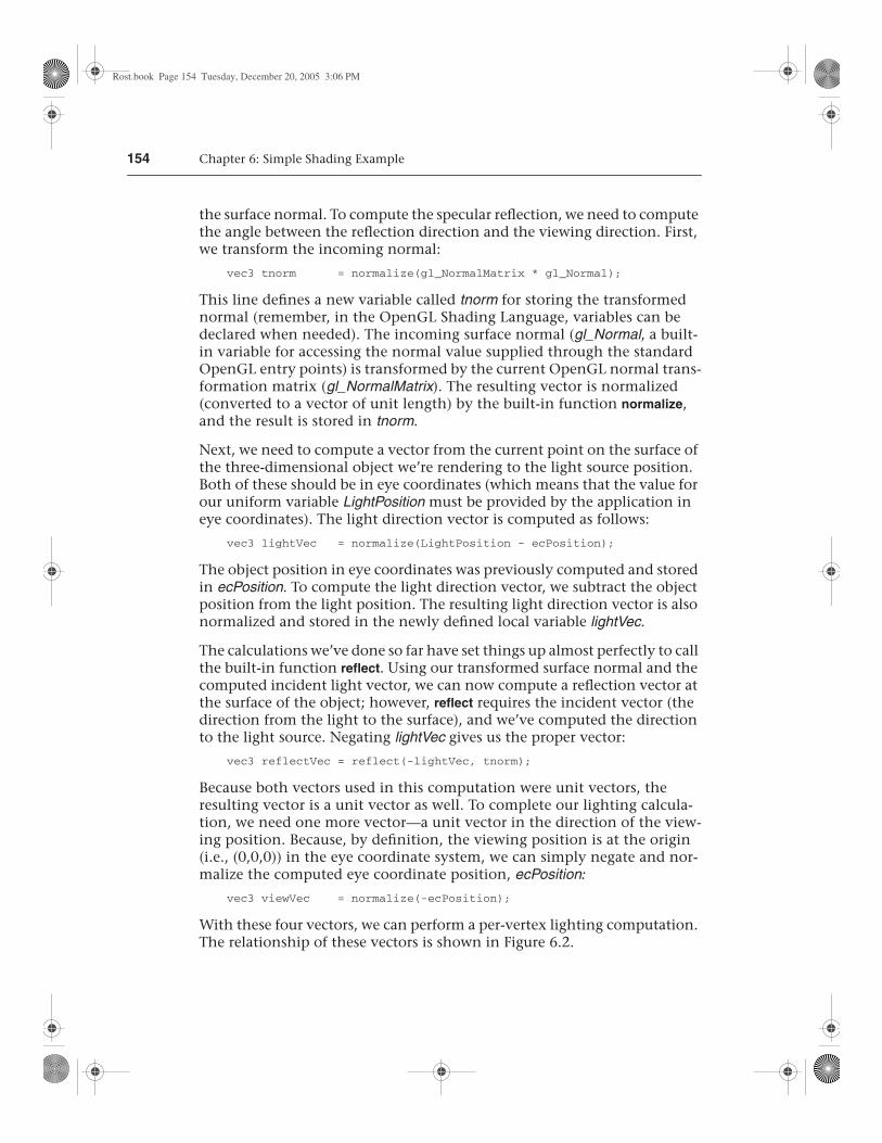
With these four vectors, we can perform a per-vertex lighting computation. The relationship of these vectors is shown in Figure 6.2.
Rost.book Page 154 Tuesday, December 20, 2005 3:06 PM
6.2 Vertex Shader 155
The modeling of diffuse reflection is based on the assumption that the inci-dent light is scattered in all directions according to a cosine distribution function. The reflection of light is strongest when the light direction vector and the surface normal are coincident. As the difference between the two angles increases to 90o, the diffuse reflection drops off to zero. Because both vectors have been normalized to produce unit vectors, we can determine the cosine of the angle between lightVec and tnorm by performing a dot product operation between those vectors. We want the diffuse contribution to be 0 if the angle between the light and the surface normal is greater than 90o (there should be no diffuse contribution if the light is behind the object), and the max function accomplishes this:
float diffuse = max(dot(lightVec, tnorm), 0.0);
The specular component of the light intensity for this vertex is computed by
float spec = 0.0; if (diffuse > 0.0) { spec = max(dot(reflectVec, viewVec), 0.0); spec = pow(spec, 16.0); }
lightVec
tnorm
viewVec
reflectVec
lightPositionecPosition
Figure 6.2 Vectors involved in the lighting computation for the brick vertex shader
Rost.book Page 155 Tuesday, December 20, 2005 3:06 PM
156 Chapter 6: Simple Shading Example
The variable for the specular reflection value is defined and initialized to 0. We compute a specular value other than 0 only if the angle between the light direction vector and the surface normal is less than 90o (i.e., the dif-fuse value is greater than 0) because we don’t want any specular highlights if the light source is behind the object. Because both reflectVec and viewVec are normalized, computing the dot product of these two vectors gives us the cosine of the angle between them. If the angle is near zero (i.e., the reflection vector and the viewing vector are almost the same), the resulting value is near 1.0. By raising the result to the 16th power in the subsequent line of code, we effectively “sharpen” the highlight, ensuring that we have a specular highlight only in the region where the reflection vector and the view vector are almost the same. The choice of 16 for the exponent value is arbitrary. Higher values produce more concentrated specular highlights, and lower values produce less concentrated highlights. This value could also be passed in as a uniform variable so that it can be easily modified by the end user.
All that remains is to multiply the computed diffuse and specular reflection values by the diffuseContribution and specularContribution constants and sum the two values:
LightIntensity = DiffuseContribution * diffuse + SpecularContribution * spec;
This value will be assigned to the varying variable LightIntensity and inter-polated between vertices. We also have one other varying variable to com-pute, and we can do that quite easily:
MCposition = gl_Vertex.xy;
When the brick pattern is applied to a geometric object, we want the brick pattern to remain constant with respect to the surface of the object, no mat-ter how the object is moved. We also want the brick pattern to remain con-stant with respect to the surface of the object, no matter what the viewing position. To generate the brick pattern algorithmically in the fragment shader, we need to provide a value at each fragment that represents a loca-tion on the surface. For this example, we provide the modeling coordinate at each vertex by setting our varying variable MCposition to the same value as our incoming vertex position (which is, by definition, in modeling coor-dinates).
We don’t need the z or w coordinate in the fragment shader, so we need a way to select just the x and y components of gl_Vertex. We could have used a constructor here (e.g., vec2(gl_Vertex)), but to show off another language feature, we use the component selector .xy to select the first two compo-nents of gl_Vertex and store them in our varying variable MCposition.
Rost.book Page 156 Tuesday, December 20, 2005 3:06 PM

6.3 Fragment Shader 157
All that remains to be done is what all vertex shaders must do: compute the homogeneous vertex position. We do this by transforming the incoming vertex value by the current modelview-projection matrix, using the built-in function ftransform:
gl_Position = ftransform();}
For clarity, the code for our vertex shader is provided in its entirety in Listing 6.1.
Listing 6.1 Source code for brick vertex shader
uniform vec3 LightPosition;
const float SpecularContribution = 0.3;const float DiffuseContribution = 1.0 - SpecularContribution;
varying float LightIntensity;varying vec2 MCposition;
void main(){ vec3 ecPosition = vec3(gl_ModelViewMatrix * gl_Vertex); vec3 tnorm = normalize(gl_NormalMatrix * gl_Normal); vec3 lightVec = normalize(LightPosition - ecPosition); vec3 reflectVec = reflect(-lightVec, tnorm); vec3 viewVec = normalize(-ecPosition); float diffuse = max(dot(lightVec, tnorm), 0.0); float spec = 0.0;
if (diffuse > 0.0) { spec = max(dot(reflectVec, viewVec), 0.0); spec = pow(spec, 16.0); }
LightIntensity = DiffuseContribution * diffuse + SpecularContribution * spec;
MCposition = gl_Vertex.xy; gl_Position = ftransform();}
6.3 Fragment Shader
The typical purpose of a fragment shader is to compute the color to be applied to a fragment or to compute the depth value for the fragment or both. In this case (and indeed with most fragment shaders), we’re concerned
Rost.book Page 157 Tuesday, December 20, 2005 3:06 PM
158 Chapter 6: Simple Shading Example
only about the color of the fragment. We’re perfectly happy using the depth value that’s been computed by the OpenGL rasterization stage. Therefore, the entire purpose of this shader is to compute the color of the current fragment.
Our brick fragment shader starts off by defining a few more uniform vari-ables than did the vertex shader. The brick pattern that will be rendered on our geometry is parameterized to make it easier to modify. The parameters that are constant across an entire primitive can be stored as uniform vari-ables and initialized (and later modified) by the application. This makes it easy to expose these controls to the end user for modification through user interface elements such as sliders and color pickers. The brick fragment shader uses the parameters that are illustrated in Figure 6.1. These are defined as uniform variables as follows:
uniform vec3 BrickColor, MortarColor;uniform vec2 BrickSize;uniform vec2 BrickPct;
We want our brick pattern to be applied consistently to our geometry in order to have the object look the same no matter where it is placed in the scene or how it is rotated. The key to determining the placement of the brick pattern is the modeling coordinate position that is computed by the vertex shader and passed in the varying variable MCposition:
varying vec2 MCposition;
This variable was computed at each vertex by the vertex shader in the pre-vious section, and it is interpolated across the primitive and made available to the fragment shader at each fragment location. Our fragment shader can use this information to determine where the fragment location is in relation to the algorithmically defined brick pattern. The other varying variable that is provided as input to the fragment shader is defined as follows:
varying float LightIntensity;
This varying variable contains the interpolated value for the light intensity that we computed at each vertex in our vertex shader. Note that both of the varying variables in our fragment shader are defined with the same type that was used to define them in our vertex shader. A link error would be gen-erated if this were not the case.
With our uniform and varying variables defined, we can begin with the actual code for the brick fragment shader:
void main(){ vec3 color; vec2 position, useBrick;
Rost.book Page 158 Tuesday, December 20, 2005 3:06 PM

6.3 Fragment Shader 159
In this shader, we do things more like we would in C and define all our local variables before they’re used at the beginning of our main function. In some cases, this can make the code a little cleaner or easier to read, but it is mostly a matter of personal preference and coding style. The first actual line of code in our brick fragment shader computes values for the local vec2 variable position:
position = MCposition / BrickSize;
This statement divides the fragment’s x position in modeling coordinates by the brick column width and the y position in modeling coordinates by the brick row height. This gives us a “brick row number” (position.y) and a “brick number” within that row (position.x). Keep in mind that these are signed, floating-point values, so it is perfectly reasonable to have negative row and brick numbers as a result of this computation.
Next, we use a conditional to determine whether the fragment is in a row of bricks that is offset (see Figure 6.3):
if (fract(position.y * 0.5) > 0.5) position.x += 0.5;
The “brick row number” (position.y) is multiplied by 0.5, the integer part is dropped by the fract function, and the result is compared to 0.5. Half the time (or every other row), this comparison is true, and the “brick number” value (position.x) is incremented by 0.5 to offset the entire row by half the width of a brick. This is illustrated by the graph in Figure 6.3.
0
1
1 2 3 4 5 6
2
position.y
fract(position.y * 0.5)
Amount added toposition.x
Figure 6.3 A graph of the function fract(position.y * 0.5) shows how the even/odd row determination is made. The result of this function is compared against 0.5. If the value is greater than 0.5, a value of 0.5 is added to position.x; otherwise, nothing is added. The result is that rows whose integer values are 1, 3, 5, …, are shifted half a brick position to the right.
Rost.book Page 159 Tuesday, December 20, 2005 3:06 PM
160 Chapter 6: Simple Shading Example
Following this, we compute the fragment’s location within the current brick:
position = fract(position);
This computation gives us the vertical and horizontal position within a sin-gle brick. This position serves as the basis for determining whether to use the brick color or the mortar color.
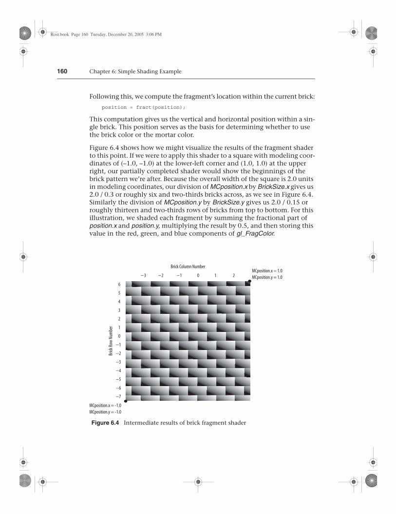
Figure 6.4 shows how we might visualize the results of the fragment shader to this point. If we were to apply this shader to a square with modeling coor-dinates of (–1.0, –1.0) at the lower-left corner and (1.0, 1.0) at the upper right, our partially completed shader would show the beginnings of the brick pattern we’re after. Because the overall width of the square is 2.0 units in modeling coordinates, our division of MCposition.x by BrickSize.x gives us 2.0 / 0.3 or roughly six and two-thirds bricks across, as we see in Figure 6.4. Similarly the division of MCposition.y by BrickSize.y gives us 2.0 / 0.15 or roughly thirteen and two-thirds rows of bricks from top to bottom. For this illustration, we shaded each fragment by summing the fractional part of position.x and position.y, multiplying the result by 0.5, and then storing this value in the red, green, and blue components of gl_FragColor.
MCposition.x = -1.0MCposition.y = -1.0
MCposition.x = 1.0MCposition.y = 1.0
6
5
4
3
2
1
0
−1
−2
−3
−4
−5
−6
−7
−3 −2 −1 0 1 2
Brick
Row
Num
ber
Brick Column Number
Figure 6.4 Intermediate results of brick fragment shader
Rost.book Page 160 Tuesday, December 20, 2005 3:06 PM
6.3 Fragment Shader 161
To complete our brick shader, we need a function that gives us a value of 1.0 when the brick color should be used and 0 when the mortar color should be used. If we can achieve this, we can end up with a simple way to choose the appropriate color. We know that we’re working with a horizontal com-ponent of the brick texture function and a vertical component. If we can create the desired function for the horizontal component and the desired function for the vertical component, we can just multiply the two values together to get our final answer. If the result of either of the individual func-tions is 0 (mortar color), the multiplication causes the final answer to be 0; otherwise, it is 1.0, and the brick color is used.
We use the step function to achieve the desired effect. The step function takes two arguments, an edge (or threshold) and a parameter to test against that edge. If the value of the parameter to be tested is less than the edge value, the function returns 0; otherwise, it returns 1.0. (Refer to Figure 5.11 for a graph of this function). In typical use, the step function produces a pattern of pulses (i.e., a square wave) whereby the function starts at 0 and rises to 1.0 when the threshold is reached. We can get a function that starts at 1.0 and drops to 0 just by reversing the order of the two arguments provided to this function:
useBrick = step(position, BrickPct);
In this line of code, we compute two values that tell us whether we are in the brick or in the mortar in the horizontal direction (useBrick.x) and in the ver-tical direction (useBrick.y). The built-in function step produces a value of 0 when BrickPct.x < position.x and a value of 1.0 when BrickPct.x >= position.x. Because of the fract function, we know that position.x varies from (0,1). The variable BrickPct is a uniform variable, so its value is constant across the primitive. This means that the value of useBrick.x is 1.0 when the brick color should be used and 0 when the mortar color should be used as we move hor-izontally. The same thing is done in the vertical direction, with position.y and BrickPct.y computing the value for useBrick.y. By multiplying useBrick.x by useBrick.y, we can get a value of 0 or 1.0 that lets us select the appropriate color for the fragment. The periodic step function for the horizontal com-ponent of the brick pattern is illustrated in Figure 6.5.
The values of BrickPct.x and BrickPct.y can be computed by the application to give a uniform mortar width in both directions based on the ratio of col-umn width to row height, or the values can be chosen arbitrarily to give a mortar appearance that looks right.
All that remains is to compute our final color value and store it in the special variable gl_FragColor:
color = mix(MortarColor, BrickColor, useBrick.x * useBrick.y); color *= LightIntensity; gl_FragColor = vec4(color, 1.0);}
Rost.book Page 161 Tuesday, December 20, 2005 3:06 PM

162 Chapter 6: Simple Shading Example
Here we compute the color of the fragment and store it in the local variable color. We use the built-in function mix to choose the brick color or the mortar color, depending on the value of useBrick.x * useBrick.y. Because useBrick.x and useBrick.y can have values of only 0 (mortar) or 1.0 (brick), we choose the brick color only if both values are 1.0; otherwise, we choose the mortar color.
The resulting value is then multiplied by the light intensity, and that result is stored in the local variable color. This local variable is a vec3, and gl_FragColor is defined as a vec4, so we create our final color value by using a constructor to add a fourth component (alpha) equal to 1.0 and assign the result to the built-in variable gl_FragColor.
The source code for the complete fragment shader is shown in Listing 6.2.
Listing 6.2 Source code for brick fragment shader
uniform vec3 BrickColor, MortarColor;uniform vec2 BrickSize;uniform vec2 BrickPct;
varying vec2 MCposition;varying float LightIntensity;
void main(){ vec3 color; vec2 position, useBrick;
0
1
1 2 3
BrickPct.x BrickPct.x+1 BrickPct.x+2
MortarColorBrickColor
Figure 6.5 The periodic step function that produces the horizontal component of the procedural brick pattern
Rost.book Page 162 Tuesday, December 20, 2005 3:06 PM

6.3 Fragment Shader 163
position = MCposition / BrickSize;
if (fract(position.y * 0.5) > 0.5) position.x += 0.5;
position = fract(position);
useBrick = step(position, BrickPct);
color = mix(MortarColor, BrickColor, useBrick.x * useBrick.y); color *= LightIntensity; gl_FragColor = vec4(color, 1.0);}
When comparing this shader to the vertex shader in the previous example, we notice one of the key features of the OpenGL Shading Language, namely, that the language used to write these two shaders is almost identical. Both shaders have a main function, some uniform variables, and some local vari-ables; expressions are the same; built-in functions are called in the same way; constructors are used in the same way; and so on. The only perceptible dif-ferences exhibited by these two shaders are (A) the vertex shader accesses built-in attribute variables, such as gl_Vertex and gl_Normal, (B) the vertex shader writes to the built-in variable gl_Position, whereas the fragment shader writes to the built-in variable gl_FragColor, and (C) the varying vari-ables are written by the vertex shader and are read by the fragment shader.
The application code to create and use these shaders is shown in Section 7.13, after the OpenGL Shading Language API has been presented. The result of rendering some simple objects with these shaders is shown in Figure 6.6. A color version of the result is shown in Color Plate 35.
Figure 6.6 A flat polygon, a sphere, and a torus rendered with the brick shaders
Rost.book Page 163 Tuesday, December 20, 2005 3:06 PM
164 Chapter 6: Simple Shading Example
6.4 Observations
A couple of problems with our shader make it unfit for anything but the simplest cases. Because the brick pattern is computed with the modeling coordinates of the incoming object, the apparent size of the bricks depends on the size of the object in modeling coordinates. The brick pattern might look fine with some objects, but the bricks may turn out much too small or much too large on other objects. At the very least, we should probably have a uniform variable in the vertex shader to scale the modeling coordinates. The application could allow the end user to adjust the scale factor to make the brick pattern look good on the object being rendered.
Another potential issue is that we’ve chosen to base the brick pattern on the object’s x and y coordinates in modeling space. This can result in some unrealistic-looking effects on objects that aren’t as regular as the objects shown in Figure 6.6. By using only the x and y coordinates of the object, we end up modeling bricks that are infinitely deep. The brick pattern looks fine when viewed from the front of the object, but when you look at it from the side, you’ll be able to see how the brick extends in depth. To get a truly three-dimensional brick shader, we’d need to add a third dimension to our procedural texture calculation and use the z component of the position in modeling coordinates to determine whether we were in brick or mortar in the z dimension as well (see if you can modify the shaders to do this).
If we look closely at our brick pattern, we also notice aliasing artifacts (jag-gies) along the transition from brick color to mortar color. These artifacts are due to the step function causing an instantaneous change from 0 to 1.0 (or from 1.0 to 0) when we cross the transition point between brick color and mortar color. Our shader has no alternative but to pick one color or the other for each fragment, and, because we cannot sample at a high enough frequency to represent this instantaneous change at the brick/mortar bor-der, aliasing artifacts occur. Instead of using the step function, we could have used the built-in smoothstep function. This function is like the step function, except that it defines two edges and a smooth interpolation between 0 and 1.0 between those two edges. This would have the effect of blurring the transition between the brick color and the mortar color, thus making the aliasing artifacts much less noticeable. A method for analyti-cally antialiasing the procedural brick texture is described in Section 17.4.5.
Despite these shortcomings, our brick shaders are perfectly good examples of a working OpenGL shader. Together, our brick vertex and fragment shad-ers illustrate a number of the interesting features of the OpenGL Shading Language.
Rost.book Page 164 Tuesday, December 20, 2005 3:06 PM
165
6.5 Summary
This chapter has applied the language concepts from previous chapters to the development of working shaders that create a procedurally defined brick pattern. The vertex shader is responsible for transforming the vertex posi-tion, passing along the modeling coordinate position of the vertex, and computing a light intensity value at each vertex, using a single simulated light source. The fragment shader is responsible for determining whether each fragment should be brick color or mortar color. Once this determina-tion is made, the light intensity value is applied to the chosen color, and the final color value is passed from the fragment shader so that it can ultimately be written in the frame buffer. The source code for these two shaders was dis-cussed line by line to explain clearly how they work. This pair of shaders illustrates many of the features of the OpenGL Shading Language and can be used as a springboard for doing bigger and better things with the language.
6.6 Further Information
This shader and others are available from the 3Dlabs developer Web site. Source code for getting started with OpenGL shaders is also available.
[1] 3Dlabs developer Web site. http://developer.3dlabs.com/
[2] Baldwin, Dave, OpenGL 2.0 Shading Language White Paper, Version 1.0, 3Dlabs, October, 2001.
[3] Ebert, David S., John Hart, Bill Mark, F. Kenton Musgrave, Darwyn Peachey, Ken Perlin, and Steven Worley, Texturing and Modeling: A Procedural Approach, Third Edition, Morgan Kaufmann Publishers, San Francisco, 2002. http://www.texturingandmodeling.com
[4] Kessenich, John, Dave Baldwin, and Randi Rost, The OpenGL Shading Language, Version 1.10, 3Dlabs, April 2004. http://www.opengl.org/documentation/spec.html
[5] Segal, Mark, and Kurt Akeley, The OpenGL Graphics System: A Specification (Version 2.0), Editor (v1.1): Chris Frazier, (v1.2–1.5): Jon Leech, (v2.0): Jon Leech and Pat Brown, Sept. 2004. http://www.opengl.org/documentation/spec.html
6.6 Further Information
Rost.book Page 165 Tuesday, December 20, 2005 3:06 PM

Rost.book Page 166 Tuesday, December 20, 2005 3:06 PM


![Error Reduction and Simplification for Shading Anti … Reduction...The shading anti-aliasing technique [Kaplanyan et al. 2016] is a simple solution for specular aliasing. This report](https://static.fdocuments.in/doc/165x107/5ecad9ce1f17ac05191723c9/error-reduction-and-simplification-for-shading-anti-reduction-the-shading-anti-aliasing.jpg)