6j-manual -
99
6J -2.4 GHz INSTRUCTION MANUAL for Futaba 6J-2.4GHz 6-channel, S-FHSS/FHSS Radio control system for Airplanes/Helicopters Futaba Corporation Technical updates available at: http://www.futaba-rc.com Entire Contents © Copyright 2011 1M23N24802
Transcript of 6j-manual -
6J-2.4GHz
INSTRUCTION MANUAL for Futaba 6J-2.4GHz
6-channel, S-FHSS/FHSS Radio control system
for Airplanes/Helicopters
Futaba Corporation
Technical updates available at: http://www.futaba-rc.com
Entire Contents © Copyright 2011 1M23N24802

2
TABLE OF CONTENTS
Introduction .............................................................3 Service ......................................................................3 Usage Precautions: ..................................................4 Contents and Specifications ...................................4 Introduction to the 6J- 2.4GHz System.................6 Transmitter controls ...............................................6 Radio Installation....................................................9 Receiver Installation: ............................................10 Receiver and Servo Connections .........................14 Charging NiCd/NiMH batteries ..........................16 Liquid Crystal Display (LCD) and Programming Controls..................................................................18 Programming the T6J-2.4GHz Radio .................19
(Common Functions) Parameter (PARA) .............................................20 Model Select Function (MODL)........................20 Model Name function ........................................21 Data Reset function (REST) ..............................22 ACRO/HELI Model type select function (TYPE). ...........................................................................23 Transmission Mode Selection (MODE) ............24 Throttle-Cut Function (TCUT) ..........................25 Battery F/S Fail Safe (S-FHSS Mode only) ......26 Servo Reversing (REVR) ..................................27 Dual Rates (ACRO) ..........................................28 Exponential Settings (EXPO) – (ACRO) ..........29 Dual Rates (HELI) ............................................30 Exponential Settings (EXPO) - HELI................32 End Point Adjustment (EPA) .............................33 Trim Settings (TRIM) ........................................34 Sub-Trims (STRM) ............................................36 (Airplane Only Programming) Programmable Mix 1 and 2 (PMX 1 and PMIX 2) (ACRO only) .....................................................37 Wing Type Selection- (ACRO only)..................38 Flaperon mixing (FLPR)- (ACRO only) ...........39 Flap trim (FLTR)- (ACRO only) .......................41 V-tail mixing (V-TL)- (ACRO only) .................42
Elevon mixing (ELVN)- (ACRO only)..............43 Throttle Curve (T-CV)- (ACRO only) ...............44 Pitch Curve (P-CV)- (ACRO only) ...................45 (Helicopter Only Programming) Normal throttle curve function (N-TH)- (HELI only)-..................................................................47 Normal pitch curve (N-PI)-(HELI only)............48 Idle Up throttle curve function (I-TH)- (HELI Only) ..................................................................49 Pitch Curve Idle UP (I-PI) - (HELI only) ..........51 Throttle hold function (HOLD)- (HELI only) ...52 Pitch Curve Hold (H-PI)- (HELI only)..............53 Revolution Mixing (REVO) - (HELI only) .......54 Gyro mixing function (GYRO)-(HELI only) ....55 Swash to throttle mixing (SW-T)-(HELI only)..57 Swash Ring (RING)...........................................57 Swashplate type selection and Swash AFR (SWSH) - (HELI only) ......................................58 Swashplate AFR (Adjustable Function Rate) - (HELI only) .......................................................60 Delay (DELY)- (HELI only)..............................61 Hovering Pitch (HOVP)- (HELI only) ..............62 (Other Programming function) Fail Safe (F/S) ....................................................63 TRNR Trainer function ......................................64 TIMER ...............................................................67
Flow Chart ACRO Mode Functions....................70 Adjustable length control sticks ..........................72 Changing the T6J Stick Mode .............................72 Flying Safety Guidelines.......................................73 Charge the batteries..............................................73 Flight Preparation.................................................74 Check the controls.................................................74 GLOSSARY...........................................................75
3
INTRODUCTION
Thank you for purchasing the Futaba 6J digital proportional R/C airplane/helicopter system. This radio has been designed and manufactured to provide you with many, many years of modeling enjoyment and fun. Whether this is your first venture into RIC or you're a seasoned veteran, the 6J offers something for everyone. If this is your first 'computer' radio, rest assured that this system is designed to make initial setup and field- tuning of your airplane andIor helicopter easier and more accurate than using a non-computer 'analog' radio. Experienced modelers will appreciate some of the 6J's advanced features and functions normally found on the more advanced radios. In either case, to make the best use of the Futaba 6J system, and to operate it safely, you should carefully read the instructions in their entirety prior to operation.
Every modeler has their own personal preferences on the proper steps to set-up and program their models. As such, it would be very difficult to create a manual that would satisfy all modelers accordingly. Thus, this manual has been designed to 'step you through' the programming of the T6J transmitter, following the function list of the system. If you wish to follow your own personal preference on setting up a model, please feel free to do so keeping in mind that some programming options will interact with others. For example, dual rates and EPA will influence one another.
Suggestion: If, while reading the instructions, you are unclear of some of the procedures or functions described or become 'stuck', please continue reading anyway. Oftentimes, the function or procedure will be explained again later in an alternate manner which will clarify the procedure or function. Another alternative is to connect the battery, servos, receiver, etc. to simulate your aircraft and actually program the radio accordingly. This will allow you to visually recognize the effects of your programming inputs. If utilizing this alternate method of familiarizing yourself with your radio, please ensure that your aircraft can not cause harm to yourself or others by disabling it accordingly.
Service (USA only) If any difficulties are encountered while setting up or operating your system, please consult the instruction manual first. For further assistance you may also refer to your hobby dealer, or contact the Futaba Service Center at the web site, email address, fax number, or telephone number below.
www.futaba-rc.com email: [email protected] Fax:
(217)-398-7721 Telephone: (217)-398-8970 (option 2)
As of this writing, the Futaba Service Center assistance is available from 8:00 AM to 5:00 PM Central Standard Time, Monday through Friday. This is subject to change at any time, however. If you are unable to resolve the difficulty, pack
the system in its original packaging. Please also include a note that provides a thorough and accurate description of the difficulties experienced. Please include the following information in your note:
• Symptoms • Inventory of enclosed items • The items that require repair • Contact information-name, address, telephone
number and email address • If items are to be considered for warranty repair,
please also include a copy of the proof of purchase or purchase receipt
The equipment should be sent to the Futaba Service Center at the address below:
Futaba Service Center 3002 North Apollo Drive Suite 1
Champaign, IL 61822
4
This product is to be used for the flying of radio controlled models only. Futaba is not responsible for the results of use of this product by the customer or for any alteration of this product including modification or incorporation into other devices by third parties. Modification will void any warranty and is done at the owner's risk and responsibility.
(USA only) Please protect the environment by disposing of rechargeable batteries responsibly. Throwing rechargeable batteries into the trash or municipal waste system is illegal in some areas. Call 1-800-BATTERY for information about NiCd battery recycling in your area.
USAGE PRECAUTIONS:
1) Please obey all regulations to enjoy safe modeling. 2) Please keep the model in sight at all times as large objects can negatively impact the RF signal. Please keep in mind that objects such as wire fences and wire mesh will also cause degradation of the RF signal.
CONTENTS AND SPECIFICATIONS
Transmitter: T6J- 2.4GHz FHSS system • 6-Channel - 2.4GHz FHSS transmitter • Transmitting on 2.4GHz band • Operating system: 2-stick, 6-channel system • Power supply: 4-AA 1.2V Dry Cell batteries; 4.8V
total (sold separately) • Current drain: 120mA
Receiver: R2006GS • 6-Channel FHSS receiver • Receiving on 2.4GHz band • Power requirement: 4.8 or 7.4 volts (shared with
servos)(*1) • Current drain: 80mA (at no signal) • Size: 1.69 x 0.94 x 0.31 inches (42.9 x 23.8 x 7.9
millimeters) • Weight: 0.30 Ounces (8.3 grams)
(*1) Note: Never use dry cell batteries for the R2006GS receiver as this may cause difficulties with the receiver's operation.
GLOSSARY
It will be helpful to understand the following terms before reading the rest of this manual. The terms are not in alphabetical order, but are in a logical order that prepares the reader for better understanding the next term. For additional terminology, please refer to the complete glossary that is located elsewhere in this manual.
5
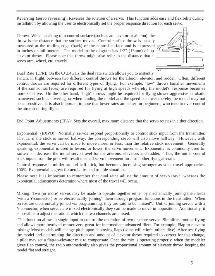
Reversing (servo reversing): Reverses the rotation of a servo. This function adds ease and flexibility during installation by allowing the user to electronically set the proper response direction for each servo.
Throw: When speaking of a control surface (such as an elevator or aileron), the throw is the distance that the surface moves. Control surface throw is usually measured at the trailing edge (back) of the control surface and is expressed in inches or millimeters. The model in the diagram has 1/2” (13mm) of up elevator throw. Please note that throw might also refer to the distance that a servo arm, wheel, etc. travels.
Dual Rate (D/R): On the 6J 2.4GHz the dual rate switch allows you to instantly switch, in flight, between two different control throws for the aileron, elevator, and rudder. Often, different control throws are required for different types of flying. For example, "low" throws (smaller movements of the control surfaces) are required for flying at high speeds whereby the model's response becomes more sensitive. On the other hand, "high" throws might be required for flying slower aggressive aerobatic maneuvers such as hovering, or when landing the model and the speed is slower thereby the model may not be as sensitive. It is also important to note that lower rates are better for beginners, who tend to over-control the aircraft during flight.
End Point Adjustments (EPA): Sets the overall, maximum distance that the servo rotates in either direction.
Exponential (EXPO): Normally, servos respond proportionally to control stick input from the transmitter. That is, if the stick is moved halfway, the corresponding servo will also move halfway. However, with exponential, the servo can be made to move more, or less, than the relative stick movement. Generally speaking, exponential is used to lessen, or lower, the servo movement. Exponential is commonly used to 'soften' or decrease the initial servo travel for the ailerons, elevators and rudder. Thus, the initial control stick inputs from the pilot will result in small servo movement for a smoother flying aircraft. Control response is milder around half-stick, but becomes increasing stronger as stick travel approaches 100%. Exponential is great for aerobatics and trouble situations. Please note it is important to remember that dual rates adjust the amount of servo travel whereas the exponential adjustments determine where most of the travel will occur.
Mixing: Two (or more) servos may be made to operate together either by mechanically joining their leads (with a Y-connector) or be electronically 'joining' them through program functions in the transmitter. When servos are electronically joined via programming, they are said to be "mixed". Unlike joining servos with a Y-connector, when servos are mixed electronically they can be made to move in opposition. Additionally, it is possible to adjust the ratio at which the two channels are mixed. This function allows a single input to control the operation of two or more servos. Simplifies routine flying
and allows more involved maneuvers-great for intermediate-advanced fliers. For example, Flap-to-elevator mixing: Most models will change pitch upon deploying flaps (some will climb; others dive). After test flying the model and determining the direction and amount of elevator throw required to correct for this change, a pilot may set a flap-to-elevator mix to compensate. Once the mix is operating properly, when the modeler gives flap control, the radio automatically also gives the proportional amount of elevator throw, keeping the model flat and straight.
INTRODUCTION TO THE 6J- 2.4GHZ SYSTEM
Important! Always turn on the transmitter first, then the receiver. When turning off the system, always turn off the receiver first. The receiver should never be on without the transmitter on. Following this procedure will prevent damage to the servos and/or control surfaces. Or, in the case of electric-powered models, the motor may unexpectedly turn on causing severe injury.
Transmitter One of the many advantages of a computerized transmitter, like the T6J, is that they allow for functionality for both airplane and helicopter applications. ACRO mode: This is the model selection that should be utilized for control of fixed wing, (airplane) aircraft. External switches operate dual rates (DIR), landing gear and trainer cord or "buddy box" capabilities. Programming features include servo reversing and EPA on all channels, dual rates, exponentials and programmable mixing. Additionally, any one of four, factory-set, pre-programmed mixers including flaperon and V-tail, elevon mixing may be selected. HELI mode: The T6J also includes the necessary programming necessary to control rotary wing (helicopter) models. The T6J includes dual rate (D/R), idle up, throttle hold, and gyro sensitivity can be operated by the switches. Additional, programming features include servo reversing and EPA on all channels, dual rates, exponentials, throttle curve, pitch curve, throttle hold and pitch to rudder mixing (REVO). Additionally, any one of four factory-set, preprogrammed "swashplate type" mixers, including three different servo type 3-s, or 3-E, may be selected.
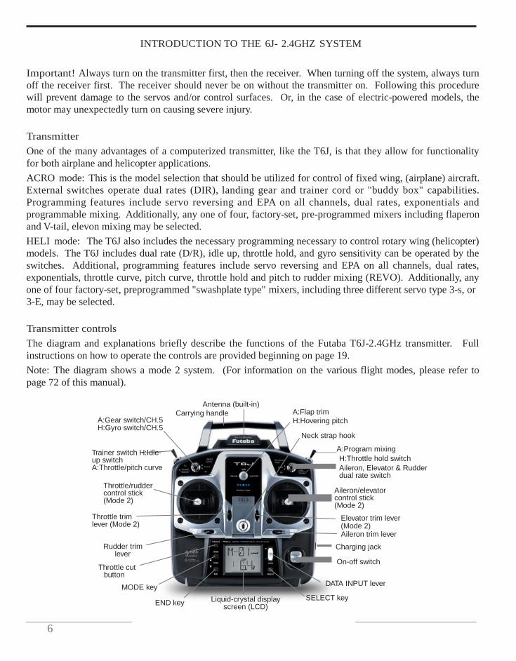
Transmitter controls The diagram and explanations briefly describe the functions of the Futaba T6J-2.4GHz transmitter. Full instructions on how to operate the controls are provided beginning on page 19. Note: The diagram shows a mode 2 system. (For information on the various flight modes, please refer to page 72 of this manual).
A:Gear switch/CH.5 H:Gyro switch/CH.5
Trainer switch H:Idle-up switch A:Throttle/pitch curve
Throttle/rudder control stick (Mode 2)
Throttle trim lever (Mode 2)
Rudder trim
lever
Throttle cut button
MODE key
Antenna (built-in) Carrying handle
A:Flap trim H:Hovering pitch
Neck strap hook
A:Program mixing H:Throttle hold switch Aileron, Elevator & Rudder dual rate switch
Aileron/elevator control stick (Mode 2)
Elevator trim lever (Mode 2) Aileron trim lever
Charging jack
On-off switch
DATA INPUT lever
END key Liquid-crystal display
screen (LCD) SELECT key
6
7
Descriptions:
Note: A: indicates functions that are only found when the T6J is in the ACRO (airplane) mode. H: indicates functions that are only found when the T6J is in the HELI (helicopter) mode. If neither an A: or H: is indicated the function is applicable to both ACRO and HELI modes.
Aileron, Elevator and Rudder dual rate switch: use this switch to select between two aileron, elevator and rudder control throw settings. The throws can be set up however you prefer. Generally speaking, when the switch is in the 'up' position, the control throws are greater ("high rate"). Conversely, when the switch is in the 'down' position, the throws are reduced ("low rate"). This switch also controls the exponential rates, if applicable. Note: The T6J allows modelers to assign the dual rates to various switches. Please refer to the dual rate section of this manual for additional information.
A: Flaps/channel 6- This switch operates the servo connected to channel six in the receiver. If your model is equipped with flaps, this is the control used to operate them accordingly. VR (rotary knob) is the default control for this channel. Note: The T6J allows modelers to assign the flaps to various switches, or the rotary knob, as desired. Please refer to the flapsIflaperon section of this manual for additional information.
H: Throttle hold switch- This switch will "hold" the engine in an idling position and disengage it from the throttle stick. It is commonly used to practice autorotation skills for helicopter pilots.
Neck strap hook: Some modelers prefer to fly with the optional neck straps. Available separately, the neck strap allows the transmitter to hang around the neck and relieve some of the weight from your hands.
Aileron/elevator control stick: Operates the servos connected to channel 1 (aileron) and channel 2 (elevator) in the receiver. (Mode 2)
Trim levers (all): Used to shift the neutral or center position of each servo as labeled in the diagram. Once any trim lever is operated, the trim position is displayed on the LCD screen.
Note: The throttle trim lever is intended to fine-tune the throttle servo when the engine is at idle. Throttle trim does not affect the throttle servo when the throttle control stick is all the way up (so idle rpm can be adjusted without affecting throttle settings through the rest of the stick movement).
Charging jack: Port used for charging the transmitter batteries (if applicable). The T6J does not include rechargeable transmitter batteries or the AC charger. However, these items are available separately at your local hobby shop, if desired.
On/Off switch: Used to power the T6J on or off.
DATA Input Lever: Used to change the values of the various functions displayed on the LCD screen.
8
Liquid Crystal Display: Commonly referred to as LCD, this is the screen of the transmitter that displays the programming modes, values entered, etc.
MODE key: Used to scroll through and display the different functions.
SELECT key: Used to display the values for the current function.
Throttle cut button: This button activates the throttle cut function and is used to fully close the carburetor and shut off the engine.
Throttle/Rudder control stick: Operates the servos connected to channel 3 (throttle) and channel 4 (rudder) in the receiver. (Mode 2)
Trainer switch: Operates the trainer functions. To operate as a trainer switch, the transmitter must be connected to another transmitter via a trainer cord (sold separately). See page ?? for more information on this feature.
H: Idle Up switch: This switch operates to change the flight condition which sets the throttle curve and pitch curve for mid-air maneuvers (rolls, loops, stall turns) and 3D flight.
A: Retractable landing gear switch/channel 5: This switch operates the servo connected to channel 5 in the receiver. If your model has retractable landing gear, this is the control used to extend and retract the gear.
H: Gyro switch/channel 5: You can connect your gyro's sensitivity adjustment connector to channel 5 of the receiver to operate the gyro. The T6J offers two different sensitivity settings.
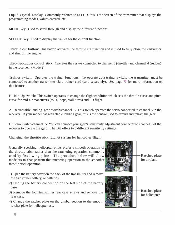
Changing the throttle stick ratchet system for helicopter flight:
Generally speaking, helicopter pilots prefer a smooth operation of the throttle stick rather than the ratcheting operation commonly used by fixed wing pilots. The procedure below will allow modelers to change from this ratcheting operation to the smoother throttle stick operation.
1) Open the battery cover on the back of the transmitter and remove the transmitter battery, or batteries.
2) Unplug the battery connection on the left side of the battery case.
3) Remove the four transmitter rear case screws and remove the rear case.
4) Change the ratchet plate on the gimbal section to the smooth ratchet plate for helicopter use.
Ratchet plate for airplane Ratchet plate for helicopter

9
RADIO INSTALLATION
Follow these guidelines to properly mount the servos, receiver and battery.
• Make certain that the alignment tab on the battery, switch and servo connectors are oriented correctly and that the "keys" on the connectors correspond to the notch in the receiver or connectors before plugging them in. When unplugging connectors never pull directly on the wires. Instead, pull directly on the plastic connectors. Doing so will prevent any damage to the wires.
• If any servo wires are not long enough to reach the desired connection point, Futaba offers a complete range
of servo extensions which may be purchased separately for this application.
• Always mount the servos with the supplied rubber grommets. Do not over-tighten the screws. No part of the servo casing should contact the mounting rails, servo tray or any other part of the airplane/helicopter structure. If they do so, vibration will be transmitted to the servo itself causing premature wear and/or servo failure.
Servo
Rubber
grommet Servo
Rubber
grommet
• Note the small numbers (1-4) molded into each arm of the Futaba 4-arm servo arms. The numbers indicate how many degrees each arm is 'off' from 90 degrees. These may be used to correct slight manufacturing deviances between servos and ensure the proper geometric set-up for the aircraft.
• To center the servos, connect them to the receiver and turn on
the transmitter followed by the receiver. Center the trims on the transmitter, then find the arm that will be perfectly perpendicular (90 degrees) to the pushrod when placed on the servo.
• After the servos are installed, operate each servo over its full travel and check that the pushrods and servo arms do not bind or contact each other. Also, make sure that the controls do not require excess force to operate. If there is any objectionable buzzing sound coming from a servo, there is probably too much resistance in the control. Find and correct the difficulty.
• Use the mounting plate from the receiver on/off switch as a template for the cutout and screw holes.
Mount the switch on the side of the fuselage opposite the engine exhaust and in a location where it won't be inadvertently turned on or off during handling or storage of the aircraft. The cutout should allow for a full range of motion from the switch in both directions. Be certain that the switch moves without and restrictions and that it 'snaps' from on to off.
• When you install the switch harness in the helicopter, please use the switch cover. Generally, sandwich
the frame by the switch and switch cover and securely tighten the screws. Different models might require different installations. In that case, please follow the directions supplied by the manufacturer.
10
• To prevent the servo lead wires from being broken by vibration during flight, provide a bit of slack so that the wire is not pulling against the servo or connector going to the receiver. In addition, periodically check the wire during pre-flight routine.
Fasten about 5-10cm from the servo outlet so that the lead wire is neat.
Margin in the lead wire.
IMPORTANT: In order to maximize the performance and enjoyment of the Futaba T6J transmitter, please read this section carefully and completely.
Receiver Installation:
• In order to obtain the best possible performance from your 2.4GHz aircraft receiver, we have developed the
following guidelines and suggestions.
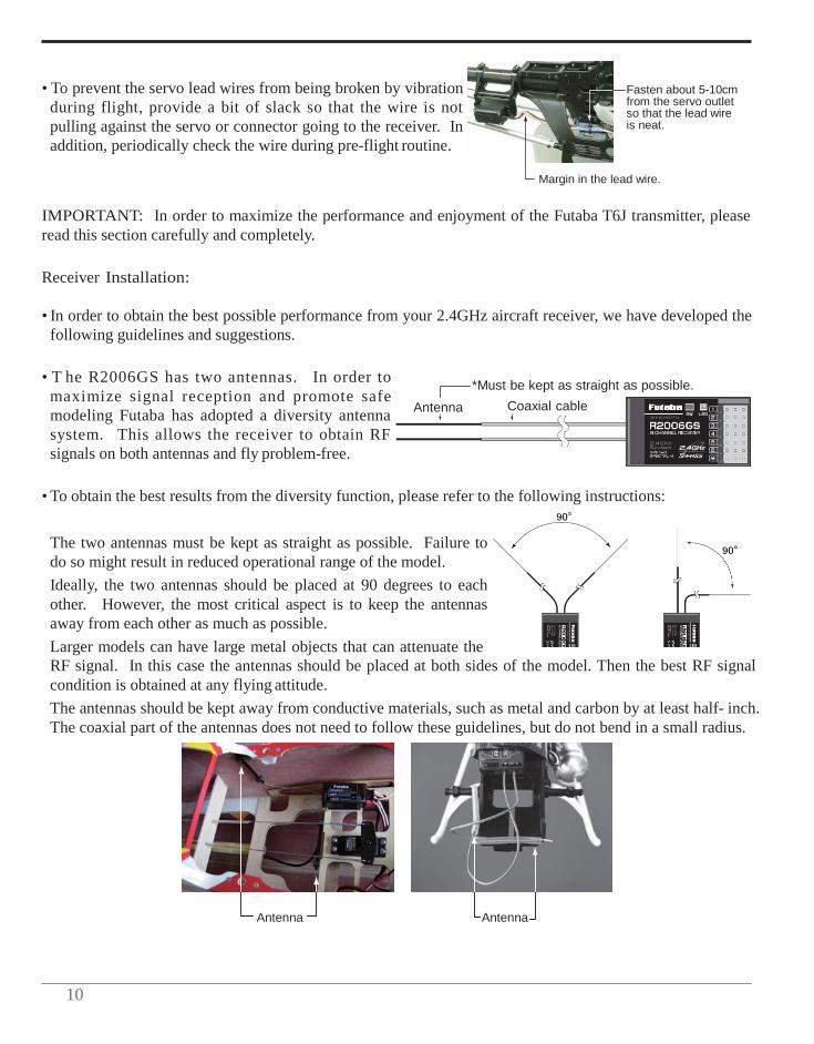
• T he R2006GS has two antennas. In order to maximize signal reception and promote safe modeling Futaba has adopted a diversity antenna system. This allows the receiver to obtain RF signals on both antennas and fly problem-free.
Antenna
*Must be kept as straight as possible.
Coaxial cable
• To obtain the best results from the diversity function, please refer to the following instructions:
The two antennas must be kept as straight as possible. Failure to do so might result in reduced operational range of the model. Ideally, the two antennas should be placed at 90 degrees to each other. However, the most critical aspect is to keep the antennas away from each other as much as possible. Larger models can have large metal objects that can attenuate the RF signal. In this case the antennas should be placed at both sides of the model. Then the best RF signal condition is obtained at any flying attitude. The antennas should be kept away from conductive materials, such as metal and carbon by at least half- inch. The coaxial part of the antennas does not need to follow these guidelines, but do not bend in a small radius.
Antenna Antenna
1
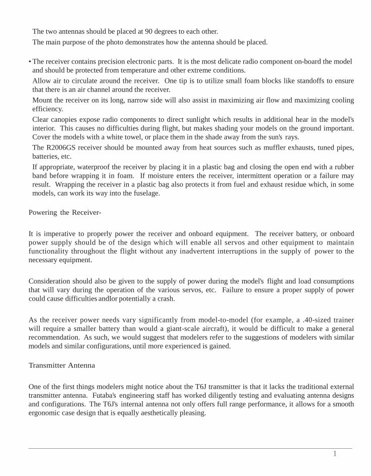
The two antennas should be placed at 90 degrees to each other. The main purpose of the photo demonstrates how the antenna should be placed.
• The receiver contains precision electronic parts. It is the most delicate radio component on-board the model and should be protected from temperature and other extreme conditions. Allow air to circulate around the receiver. One tip is to utilize small foam blocks like standoffs to ensure that there is an air channel around the receiver. Mount the receiver on its long, narrow side will also assist in maximizing air flow and maximizing cooling efficiency. Clear canopies expose radio components to direct sunlight which results in additional hear in the model's interior. This causes no difficulties during flight, but makes shading your models on the ground important. Cover the models with a white towel, or place them in the shade away from the sun's rays. The R2006GS receiver should be mounted away from heat sources such as muffler exhausts, tuned pipes, batteries, etc. If appropriate, waterproof the receiver by placing it in a plastic bag and closing the open end with a rubber band before wrapping it in foam. If moisture enters the receiver, intermittent operation or a failure may result. Wrapping the receiver in a plastic bag also protects it from fuel and exhaust residue which, in some models, can work its way into the fuselage.
Powering the Receiver-
It is imperative to properly power the receiver and onboard equipment. The receiver battery, or onboard power supply should be of the design which will enable all servos and other equipment to maintain functionality throughout the flight without any inadvertent interruptions in the supply of power to the necessary equipment.
Consideration should also be given to the supply of power during the model's flight and load consumptions that will vary during the operation of the various servos, etc. Failure to ensure a proper supply of power could cause difficulties andIor potentially a crash.
As the receiver power needs vary significantly from model-to-model (for example, a .40-sized trainer will require a smaller battery than would a giant-scale aircraft), it would be difficult to make a general recommendation. As such, we would suggest that modelers refer to the suggestions of modelers with similar models and similar configurations, until more experienced is gained.
Transmitter Antenna
One of the first things modelers might notice about the T6J transmitter is that it lacks the traditional external transmitter antenna. Futaba's engineering staff has worked diligently testing and evaluating antenna designs and configurations. The T6J's internal antenna not only offers full range performance, it allows for a smooth ergonomic case design that is equally aesthetically pleasing.
12
RANGE CHECK THE RADIO
A range check must be performed before the first flight of a new model. It is not necessary to do a range check before every flight (but is not a bad idea to perform a range check before the first flight of each day). A range check is the final opportunity to reveal any radio malfunctions, and to be certain the system has adequate operational range.
We have installed a special "Power Down Mode" in the T6J in order to perform an operational ground range check. During this mode, the RF power is reduced in order to test the operational range of the T6J.
When activated, the "Power Down Mode" will be effective for 90 seconds prior to automatically reverting to the full range mode. In most instances, 90 seconds is more than an adequate amount of time to allow for a complete range check.
To activate the Power Down Mode and Perform A Range Check:
1) To activate the "Power Down Mode" please hold down the MODE key and then turn the transmitter switch on. When this mode is active the blue LED on the front of the transmitter will begin blinking and the transmitter will provide users with an audible and visual indication that the transmitter is in the "Power Down Mode”.
Audibly, the transmitter will beep one time every three seconds until it reaches the 90 second time limit. At which time the transmitter will beep two times and then return to the full power mode.
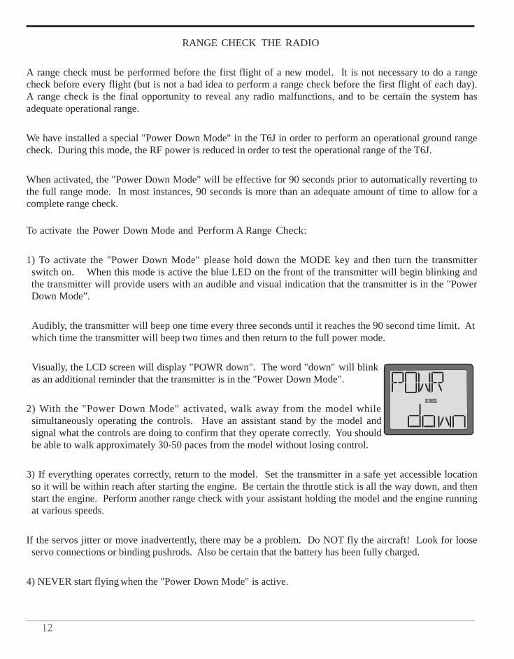
Visually, the LCD screen will display "POWR down". The word "down" will blink as an additional reminder that the transmitter is in the "Power Down Mode".
2) With the "Power Down Mode" activated, walk away from the model while simultaneously operating the controls. Have an assistant stand by the model and signal what the controls are doing to confirm that they operate correctly. You should be able to walk approximately 30-50 paces from the model without losing control.
3) If everything operates correctly, return to the model. Set the transmitter in a safe yet accessible location so it will be within reach after starting the engine. Be certain the throttle stick is all the way down, and then start the engine. Perform another range check with your assistant holding the model and the engine running at various speeds.
If the servos jitter or move inadvertently, there may be a problem. Do NOT fly the aircraft! Look for loose servo connections or binding pushrods. Also be certain that the battery has been fully charged.
4) NEVER start flying when the "Power Down Mode" is active.
1
LINKING PROCEDURE
Each transmitter has an individually assigned, unique identification code. In order to start the operation, the receiver must be linked with the identification code of the transmitter with which it is being paired. Once the link is made, the ID code is stored in the receiver and no further linking is necessary unless the receiver is to be used with another transmitter. In the case of this T6J transmitter/receiver set, the linking has already been completed at the factory. However, it is always a good safety precaution to perform this linking procedure once again, regardless.
If you've purchased a spare or additional receiver, it will be necessary to link this new receiver with your existing transmitter. In order to do so, follow the procedure below:
1) Place the transmitter and the receiver close to one another. Generally speaking, as long as the transmitter and receiver are within 39.5" (one meter), the linking procedure will proceed without any difficulties.
2) Turn on the transmitter.
3) Check the LED that is located on the face of the T6J transmitter. When the blue LED is on, and solid (no blinking), the RF signal is being transmitted.
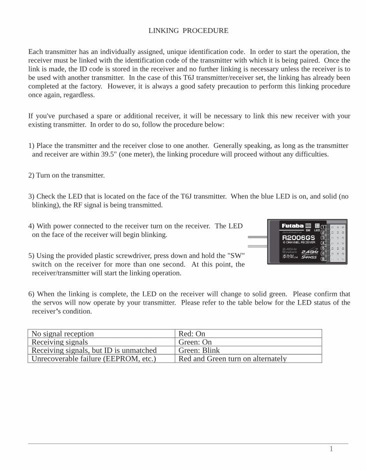
4) With power connected to the receiver turn on the receiver. The LED on the face of the receiver will begin blinking.
5) Using the provided plastic screwdriver, press down and hold the "SW" switch on the receiver for more than one second. At this point, the receiver/transmitter will start the linking operation.
6) When the linking is complete, the LED on the receiver will change to solid green. Please confirm that the servos will now operate by your transmitter. Please refer to the table below for the LED status of the receiver's condition.
No signal reception Red: On Receiving signals Green: On Receiving signals, but ID is unmatched Green: Blink Unrecoverable failure (EEPROM, etc.) Red and Green turn on alternately
14
RECEIVER AND SERVO CONNECTIONS
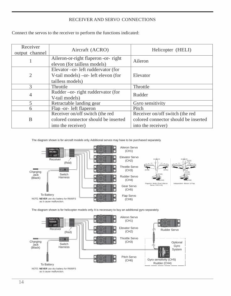
Connect the servos to the receiver to perform the functions indicated:
Receiver output channel
Aircraft (ACRO)
Helicopter (HELI)
1 Aileron-or-right flaperon -or- right elevon (for tailless models)
Aileron
2
Elevator –or- left ruddervator (for V-tail models) –or- left elevon (for tailless models)
Elevator
3 Throttle Throttle
4 Rudder –or- right ruddervator (for V-tail models)
Rudder
5 Retractable landing gear Gyro sensitivity 6 Flap -or- left flaperon Pitch
B
Receiver on/off switch (the red colored connector should be inserted into the receiver)
Receiver on/off switch (the red colored connector should be inserted into the receiver)
The diagram shown is for aircraft models only. Additional servos may have to be purchased separately.
Aileron Servo (CH1)
Charging
Receiver
(Red)
Elevator Servo
(CH2) Throttle Servo
(CH3)
(CH6)
(CH1)
(CH1)
(CH6)
Jack (Black)
To Battery
Switch Harness Rudder Servo
(CH4)
Gear Servo (CH5)
Flap Servo
(CH2)
(CH4)
Flaperon Mode (Dual Aileron Servo, CH1 & 6)
(CH2)
(CH4)
Independent Aileron & Flap
NOTE: NEVER use dry battery for R606FS as it cause malfunction.
(CH6)
The diagram shown is for helicopter models only. It is necessary to buy an additional gyro separately.
Aileron Servo
(CH1)
Receiver (Red)
Elevator Servo (CH2)
Rudder Servo
Charging
Jack (Black)
Switch
Harness
Throttle Servo
(CH3)
Optional
Gyro System
To Battery NOTE: NEVER use dry battery for R606FS
as it cause malfunction.
Pitch Servo (CH6)
Gyro sensitivity (CH5)
Rudder (CH4)
1
ALARMS AND WARNINGS
The T6J offers several different warnings and alarms that will sound if certain safety factors aren't met. For example, whether you are in airplane or helicopter mode, should the batteries drop lower than the recommended safe voltage, an alarm will sound. When in the helicopter mode there are several additional warnings/alarms that may sound: stick position, throttle hold and/or idle up activated.
These are built-in safety features to ensure the longevity of your model and your enjoyment of the hobby. We strongly suggest adhering to the warnings accordingly.
Transmitter Battery voltage-
The T6J transmitter offers a programmable low voltage alarm that warns modelers when the transmitter voltage drops below the preset low-battery setting. If you are flying when this alarm sounds, please land as quickly and safely as possible to avoid any potential difficulties.
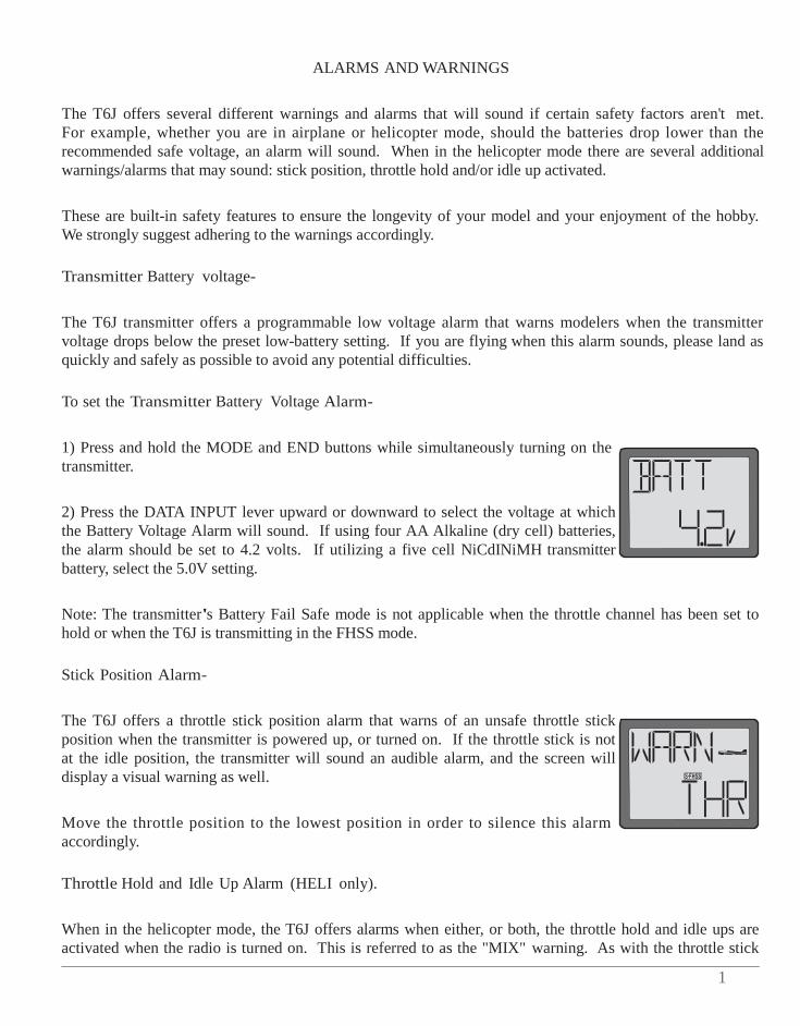
To set the Transmitter Battery Voltage Alarm-
1) Press and hold the MODE and END buttons while simultaneously turning on the transmitter.
2) Press the DATA INPUT lever upward or downward to select the voltage at which the Battery Voltage Alarm will sound. If using four AA Alkaline (dry cell) batteries, the alarm should be set to 4.2 volts. If utilizing a five cell NiCdINiMH transmitter battery, select the 5.0V setting.
Note: The transmitter's Battery Fail Safe mode is not applicable when the throttle channel has been set to hold or when the T6J is transmitting in the FHSS mode.
Stick Position Alarm-
The T6J offers a throttle stick position alarm that warns of an unsafe throttle stick position when the transmitter is powered up, or turned on. If the throttle stick is not at the idle position, the transmitter will sound an audible alarm, and the screen will display a visual warning as well.
Move the throttle position to the lowest position in order to silence this alarm accordingly.
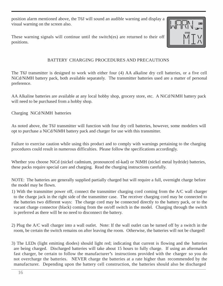
Throttle Hold and Idle Up Alarm (HELI only).
When in the helicopter mode, the T6J offers alarms when either, or both, the throttle hold and idle ups are activated when the radio is turned on. This is referred to as the "MIX" warning. As with the throttle stick
16
position alarm mentioned above, the T6J will sound an audible warning and display a visual warning on the screen also.
These warning signals will continue until the switch(es) are returned to their off positions.
BATTERY CHARGING PROCEDURES AND PRECAUTIONS
The T6J transmitter is designed to work with either four (4) AA alkaline dry cell batteries, or a five cell NiCd/NiMH battery pack, both available separately. The transmitter batteries used are a matter of personal preference.
AA Alkaline batteries are available at any local hobby shop, grocery store, etc. A NiCd/NiMH battery pack will need to be purchased from a hobby shop.
Charging NiCd/NiMH batteries
As noted above, the T6J transmitter will function with four dry cell batteries, however, some modelers will opt to purchase a NiCd/NiMH battery pack and charger for use with this transmitter.
Failure to exercise caution while using this product and to comply with warnings pertaining to the charging procedures could result in numerous difficulties. Please follow the specifications accordingly.
Whether you choose NiCd (nickel cadmium, pronounced nI-kad) or NiMH (nickel metal hydride) batteries, these packs require special care and charging. Read the charging instructions carefully.
NOTE: The batteries are generally supplied partially charged but will require a full, overnight charge before the model may be flown. 1) With the transmitter power off, connect the transmitter charging cord coming from the A/C wall charger
to the charge jack in the right side of the transmitter case. The receiver charging cord may be connected to the batteries two different ways: The charge cord may be connected directly to the battery pack, or to the vacant charge connector (black) coming from the on/off switch in the model. Charging through the switch is preferred as there will be no need to disconnect the battery.
2) Plug the A/C wall charger into a wall outlet. Note: If the wall outlet can be turned off by a switch in the room, be certain the switch remains on after leaving the room. Otherwise, the batteries will not be charged!
3) The LEDs (light emitting diodes) should light red; indicating that current is flowing and the batteries are being charged. Discharged batteries will take about 15 hours to fully charge. If using an aftermarket fast charger, be certain to follow the manufacturer's instructions provided with the charger so you do not overcharge the batteries. NEVER charge the batteries at a rate higher than recommended by the manufacturer. Depending upon the battery cell construction, the batteries should also be discharged
1
periodically to prevent a condition called "memory". If, for example, only two flights are made each time you go flying, the batteries will not have "reached" very far down into their full capacity. After doing this several times the batteries will "remember" and eventually "think" they can supply only enough power for two flights. After two flights the batteries may not provide enough power to operate the system, thus causing a crash. To erase any potential memory, cycle the NiCd batteries by discharging, then charging them with a commercial battery cycler, or leave the system on and "exercise" the servos by moving the transmitter sticks until the servos are moving very slowly, indicating that the battery is discharged. Cycling should be done every one to two months, even during the winter or periods of long storage. If using a cycler with a readout, note the capacity after the batteries have been cycled. If there is a noticeable drop in capacity the batteries should be replaced.
Note: Charging your batteries with a Futaba A/C battery charger is always safe. However, fast charging with an aftermarket charger is acceptable as long as you know how to properly operate the charger. Never charge at a rate higher than suggested by the manufacturer. If not done correctly, fast charging can damage the batteries.
Battery Care and Precautions
Below you will find some general rules and guidelines which should be adhered to when charging transmitter and/or receiver battery packs. These are included to serve only as general guidelines, and are not intended to replace or supersede the information provided by the battery and/or charger manufacturer. For complete information, please refer to the instructions that are included with the battery pack(s) and/or chargers that accompany the products purchased.
• Do not allow children to charge battery packs without adult supervision. • Do not charge battery packs that have been damaged in any way. We strongly suggest frequent inspection
of the battery packs to ensure that no damage has occurred. • Do not to allow batteries to overheat! If overheated, disconnect the battery from the charger immediately
and allow to cool. • Do not mix cells- all cells should be of the same material, configuration, etc. • Do not deep cycle NiMH batteries as permanent damage could result. • Never charge batteries on a surface that may become hot, or may be impacted by the heat. • Immediately end the charging procedure if either the batteries or charger itself become overly hot. • NiMH cells do not exhibit the "memory effect" like NiCd cells, so little cycling is needed. Store NiMH
packs with some voltage remaining on the cells (refer to battery supplier). • NiMH cells have a self-discharge rate of approximately 20-25% (compared to 15% for NiCd batteries). It is
important to recharge NiMH batteries immediately prior to use. • Never connect the battery in reverse. Reverse connection will cause the battery to overheat or will damage
the inside of the charger. • Do not add an additional charge after charging. • Never charge with a current exceeding the nominal capacity (lC) of the rechargeable battery. • If a battery is charged with a current exceeding 1C, the battery will overheat and deteriorate. • Do not connect two battery packs or more to one output terminal. • Avoid extremely cold and hot places and the direct sunlight when you charge batteries. • It is recommended to perform charging within the 10 ~ 30°C (50-85°F) range. Otherwise, it may cause
abnormal charging and overheat.
18
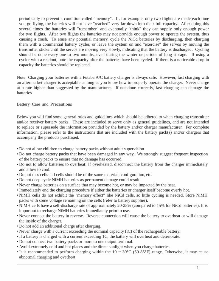
LIQUID CRYSTAL DISPLAY (LCD) AND PROGRAMMING CONTROLS
THR-CUT
MODE key - use to select desired function while programming
To open programming menu; Press MODE key for one second.
MODE
FUNC
DATA
DATA INPUT lever - use this to input numbers or settings
To close programming menu; Press END key for one second.
END SELECT
END key - use to select desired function while programming
SELECT key - use to select items within function to be set or changed in the screen
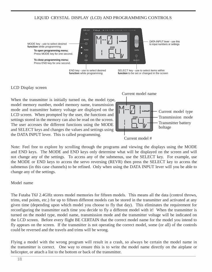
LCD Display screen
When the transmitter is initially turned on, the model type, model memory number, model memory name, transmission mode and transmitter battery voltage are displayed on the LCD screen. When prompted by the user, the functions and settings stored in the memory can also be read on the screen. The user accesses the different functions using the MODE and SELECT keys and changes the values and settings using the DATA INPUT lever. This is called programming.
Current model name
Current model #
Current model type Transmission mode Transmitter battery boltage
Note: Feel free to explore by scrolling through the programs and viewing the displays using the MODE and END keys. The MODE and END keys only determine what will be displayed on the screen and will not change any of the settings. To access any of the submenus, use the SELECT key. For example, use the MODE or END keys to access the servo reversing (REVR) then press the SELECT key to access the submenus (in this case channels) to be refined. Only when using the DATA INPUT lever will you be able to change any of the settings.
Model name
The Futaba T6J 2.4GHz stores model memories for fifteen models. This means all the data (control throws, trims, end points, etc.) for up to fifteen different models can be stored in the transmitter and activated at any given time (depending upon which model you choose to fly that day). This eliminates the requirement for reconfiguring the transmitter each time you decide to fly a different model with it! When the transmitter is turned on the model type, model name, transmission mode and the transmitter voltage will be indicated on the LCD screen. Before every flight BE CERTAIN that the correct model name for the model you intend to fly appears on the screen. If the transmitter is not operating the correct model, some (or all) of the controls could be reversed and the travels and trims will be wrong.
Flying a model with the wrong program will result in a crash, so always be certain the model name in the transmitter is correct. One way to ensure this is to write the model name directly on the airplane or helicopter, or attach a list to the bottom or back of the transmitter.
1
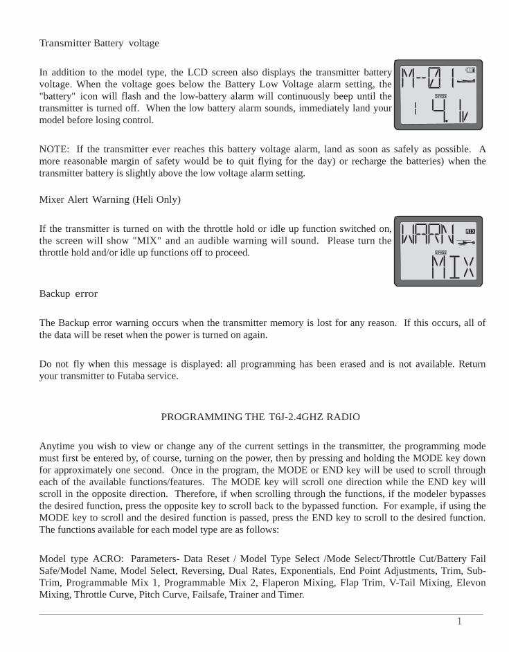
Transmitter Battery voltage
In addition to the model type, the LCD screen also displays the transmitter battery voltage. When the voltage goes below the Battery Low Voltage alarm setting, the "battery" icon will flash and the low-battery alarm will continuously beep until the transmitter is turned off. When the low battery alarm sounds, immediately land your model before losing control.
NOTE: If the transmitter ever reaches this battery voltage alarm, land as soon as safely as possible. A more reasonable margin of safety would be to quit flying for the day) or recharge the batteries) when the transmitter battery is slightly above the low voltage alarm setting.
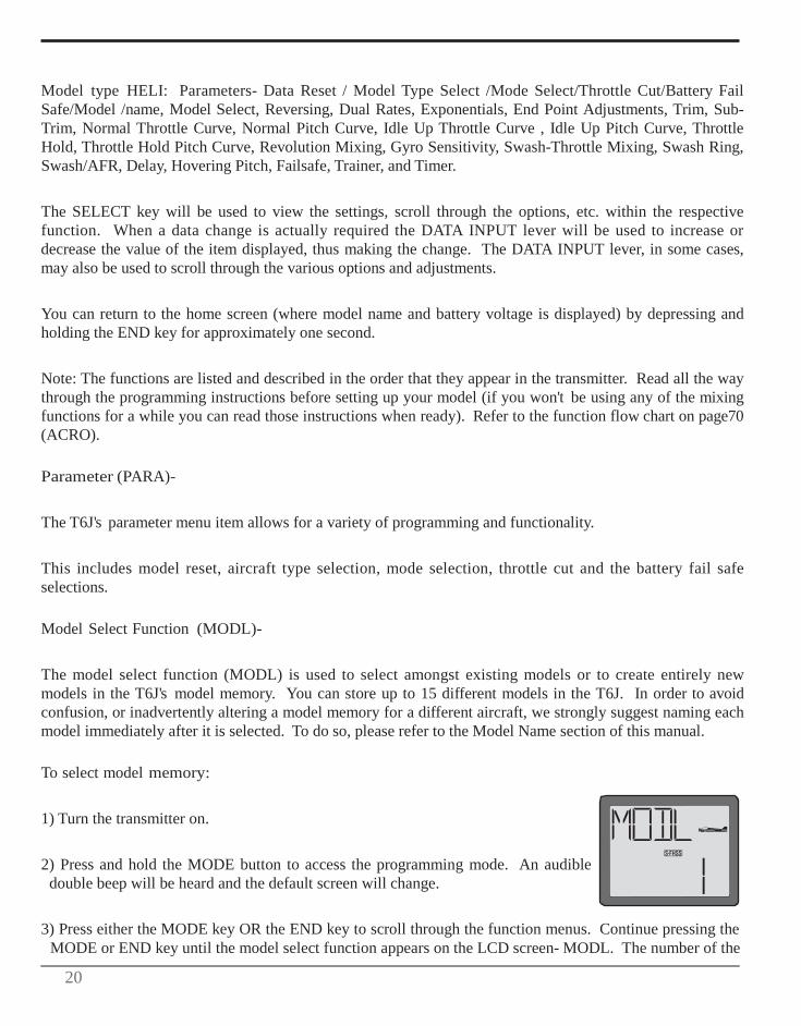
Mixer Alert Warning (Heli Only)
If the transmitter is turned on with the throttle hold or idle up function switched on, the screen will show "MIX" and an audible warning will sound. Please turn the throttle hold and/or idle up functions off to proceed.
Backup error
The Backup error warning occurs when the transmitter memory is lost for any reason. If this occurs, all of the data will be reset when the power is turned on again.
Do not fly when this message is displayed: all programming has been erased and is not available. Return your transmitter to Futaba service.
PROGRAMMING THE T6J-2.4GHZ RADIO
Anytime you wish to view or change any of the current settings in the transmitter, the programming mode must first be entered by, of course, turning on the power, then by pressing and holding the MODE key down for approximately one second. Once in the program, the MODE or END key will be used to scroll through each of the available functions/features. The MODE key will scroll one direction while the END key will scroll in the opposite direction. Therefore, if when scrolling through the functions, if the modeler bypasses the desired function, press the opposite key to scroll back to the bypassed function. For example, if using the MODE key to scroll and the desired function is passed, press the END key to scroll to the desired function. The functions available for each model type are as follows:
Model type ACRO: Parameters- Data Reset / Model Type Select /Mode Select/Throttle Cut/Battery Fail Safe/Model Name, Model Select, Reversing, Dual Rates, Exponentials, End Point Adjustments, Trim, Sub- Trim, Programmable Mix 1, Programmable Mix 2, Flaperon Mixing, Flap Trim, V-Tail Mixing, Elevon Mixing, Throttle Curve, Pitch Curve, Failsafe, Trainer and Timer.
20
Model type HELI: Parameters- Data Reset / Model Type Select /Mode Select/Throttle Cut/Battery Fail Safe/Model /name, Model Select, Reversing, Dual Rates, Exponentials, End Point Adjustments, Trim, Sub- Trim, Normal Throttle Curve, Normal Pitch Curve, Idle Up Throttle Curve , Idle Up Pitch Curve, Throttle Hold, Throttle Hold Pitch Curve, Revolution Mixing, Gyro Sensitivity, Swash-Throttle Mixing, Swash Ring, Swash/AFR, Delay, Hovering Pitch, Failsafe, Trainer, and Timer.
The SELECT key will be used to view the settings, scroll through the options, etc. within the respective function. When a data change is actually required the DATA INPUT lever will be used to increase or decrease the value of the item displayed, thus making the change. The DATA INPUT lever, in some cases, may also be used to scroll through the various options and adjustments.
You can return to the home screen (where model name and battery voltage is displayed) by depressing and holding the END key for approximately one second.
Note: The functions are listed and described in the order that they appear in the transmitter. Read all the way through the programming instructions before setting up your model (if you won't be using any of the mixing functions for a while you can read those instructions when ready). Refer to the function flow chart on page70 (ACRO).
Parameter (PARA)-
The T6J's parameter menu item allows for a variety of programming and functionality.
This includes model reset, aircraft type selection, mode selection, throttle cut and the battery fail safe selections.
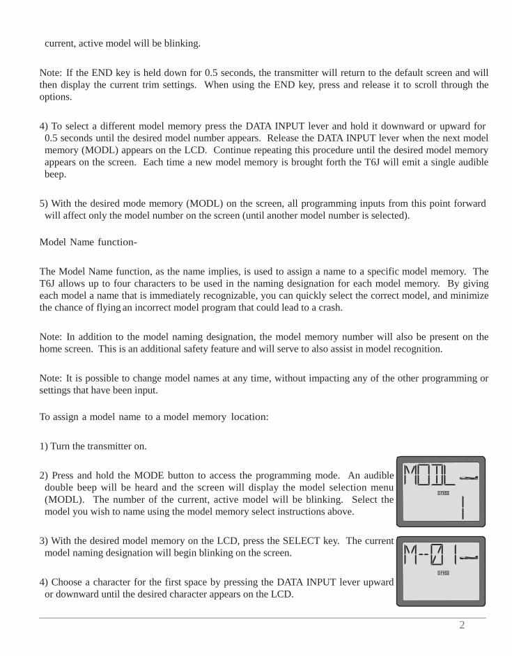
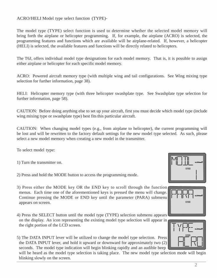
Model Select Function (MODL)-
The model select function (MODL) is used to select amongst existing models or to create entirely new models in the T6J's model memory. You can store up to 15 different models in the T6J. In order to avoid confusion, or inadvertently altering a model memory for a different aircraft, we strongly suggest naming each model immediately after it is selected. To do so, please refer to the Model Name section of this manual.
To select model memory:
1) Turn the transmitter on.
2) Press and hold the MODE button to access the programming mode. An audible double beep will be heard and the default screen will change.
3) Press either the MODE key OR the END key to scroll through the function menus. Continue pressing the MODE or END key until the model select function appears on the LCD screen- MODL. The number of the
2
current, active model will be blinking.
Note: If the END key is held down for 0.5 seconds, the transmitter will return to the default screen and will then display the current trim settings. When using the END key, press and release it to scroll through the options.
4) To select a different model memory press the DATA INPUT lever and hold it downward or upward for 0.5 seconds until the desired model number appears. Release the DATA INPUT lever when the next model memory (MODL) appears on the LCD. Continue repeating this procedure until the desired model memory appears on the screen. Each time a new model memory is brought forth the T6J will emit a single audible beep.
5) With the desired mode memory (MODL) on the screen, all programming inputs from this point forward will affect only the model number on the screen (until another model number is selected).
Model Name function-
The Model Name function, as the name implies, is used to assign a name to a specific model memory. The T6J allows up to four characters to be used in the naming designation for each model memory. By giving each model a name that is immediately recognizable, you can quickly select the correct model, and minimize the chance of flying an incorrect model program that could lead to a crash.
Note: In addition to the model naming designation, the model memory number will also be present on the home screen. This is an additional safety feature and will serve to also assist in model recognition.
Note: It is possible to change model names at any time, without impacting any of the other programming or settings that have been input.
To assign a model name to a model memory location:
1) Turn the transmitter on.
2) Press and hold the MODE button to access the programming mode. An audible double beep will be heard and the screen will display the model selection menu (MODL). The number of the current, active model will be blinking. Select the model you wish to name using the model memory select instructions above.
3) With the desired model memory on the LCD, press the SELECT key. The current model naming designation will begin blinking on the screen.
4) Choose a character for the first space by pressing the DATA INPUT lever upward or downward until the desired character appears on the LCD.
22
5) Use the SELECT key to choose the next character.
6) Repeat this procedure for the remaining two spaces. When completed, press and hold the END button. Confirm the model name on the home page.
Data Reset function (REST)-
All the data for any model memory can be reset to the original factory defaults. Often this function is performed to get a "fresh start" and clear the memory before inputting new model settings. It is also used to eliminate a model that no longer exists, from the T6J's model memory.
Note: Data reset function only resets the defaults for the model that appears on screen. It does NOT reset the entire transmitter.
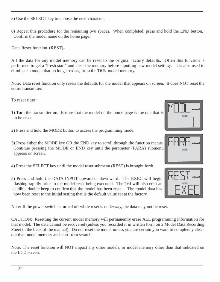
To reset data:
1) Turn the transmitter on. Ensure that the model on the home page is the one that is to be reset.
2) Press and hold the MODE button to access the programming mode.
3) Press either the MODE key OR the END key to scroll through the function menus. Continue pressing the MODE or END key until the parameter (PARA) submenu appears on screen.
4) Press the SELECT key until the model reset submenu (REST) is brought forth.
5) Press and hold the DATA INPUT upward or downward. The EXEC will begin flashing rapidly prior to the model reset being executed. The T6J will also emit an audible double beep to confirm that the model has been reset. The model data has now been reset to the initial setting that is the default value set at the factory.
Note: If the power switch is turned off while reset is underway, the data may not be reset.
CAUTION: Resetting the current model memory will permanently erase ALL programming information for that model. The data cannot be recovered (unless you recorded it in written form on a Model Data Recording Sheet in the back of the manual). Do not reset the model unless you are certain you want to completely clear- out that model memory and start from scratch.
Note: The reset function will NOT impact any other models, or model memory other than that indicated on the LCD screen.
2
ACRO/HELI Model type select function (TYPE)-
The model type (TYPE) select function is used to determine whether the selected model memory will bring forth the airplane or helicopter programming. If, for example, the airplane (ACRO) is selected, the programming features and functions which are available will be airplane-related. If, however, a helicopter (HELI) is selected, the available features and functions will be directly related to helicopters.
The T6J, offers individual model type designations for each model memory. That is, it is possible to assign either airplane or helicopter for each specific model memory.
ACRO: Powered aircraft memory type (with multiple wing and tail configurations. See Wing mixing type selection for further information, page 38).
HELI: Helicopter memory type (with three helicopter swashplate type. See Swashplate type selection for further information, page 58).
CAUTION: Before doing anything else to set up your aircraft, first you must decide which model type (include wing mixing type or swashplate type) best fits this particular aircraft.
CAUTION: When changing model types (e.g., from airplane to helicopter), the current programming will be lost and will be rewritten to the factory default settings for the new model type selected. As such, please select a new model memory when creating a new model in the transmitter.
To select model type:
1) Turn the transmitter on.
2) Press and hold the MODE button to access the programming mode.
3) Press either the MODE key OR the END key to scroll through the function menus. Each time one of the aforementioned keys is pressed the menu will change. Continue pressing the MODE or END key until the parameter (PARA) submenu appears on screen.
4) Press the SELECT button until the model type (TYPE) selection submenu appears on the display. An icon representing the existing model type selection will appear in the right portion of the LCD screen.
5) The DATA INPUT lever will be utilized to change the model type selection. Press the DATA INPUT lever, and hold it upward or downward for approximately two (2) seconds. The model type indication will begin blinking rapidly and an audible beep will be heard as the model type selection is taking place. The new model type selection mode will begin blinking slowly on the screen.
24
Note: HELI indicates that the T6J will utilize the helicopter programming and functionality. ACRO represents the airplane model type selection.
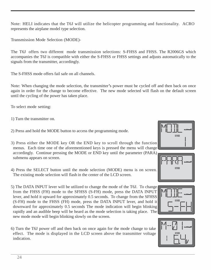
Transmission Mode Selection (MODE)-
The T6J offers two different mode transmission selections: S-FHSS and FHSS. The R2006GS which accompanies the T6J is compatible with either the S-FHSS or FHSS settings and adjusts automatically to the signals from the transmitter, accordingly.
The S-FHSS mode offers fail safe on all channels.
Note: When changing the mode selection, the transmitter's power must be cycled off and then back on once again in order for the change to become effective. The new mode selected will flash on the default screen until the cycling of the power has taken place.
To select mode setting:
1) Turn the transmitter on.
2) Press and hold the MODE button to access the programming mode.
3) Press either the MODE key OR the END key to scroll through the function menus. Each time one of the aforementioned keys is pressed the menu will change accordingly. Continue pressing the MODE or END key until the parameter (PARA) submenu appears on screen.
4) Press the SELECT button until the mode selection (MODE) menu is on screen. The existing mode selection will flash in the center of the LCD screen.
5) The DATA INPUT lever will be utilized to change the mode of the T6J. To change from the FHSS (FH) mode to the SFHSS (S-FH) mode, press the DATA INPUT lever, and hold it upward for approximately 0.5 seconds. To change from the SFHSS (S-FH) mode to the FHSS (FH) mode, press the DATA INPUT lever, and hold it downward for approximately 0.5 seconds The mode indication will begin blinking rapidly and an audible beep will be heard as the mode selection is taking place. The new mode mode will begin blinking slowly on the screen.
6) Turn the T6J power off and then back on once again for the mode change to take effect. The mode is displayed in the LCD screen above the transmitter voltage indication.

2
Throttle-Cut Function (TCUT)-
The Throttle Cut function is intended to be used for shutting off the engine, or disarming the speed control in electric-powered models. Pressing the "THR Cut" button, will shut off the engine, or disarm the ESC, accordingly. In internal combustion models, the throttle cut feature prevents inadvertently shutting off of the engine when lowering the throttle stick all the way (such as when coming in for a landing). When used in electric-powered applications, it will prevent inadvertent operation of the speed control.
As mentioned above, the T6J offers two versions of the Throttle-Cut (TCUT) function. The normal (NOR) is to be used for internal combustion engines. The electronic speed control (ESC) is to be used for electric- powered models.
To program the Throttle-Cut (TCUT) Function (Normal):
1) At the model select screen, press either the MODE or END button until the PARA (Parameter) screen appears.
2) Press SELECT until the TCUT (Throttle-Cut) screen appears. The normal (NOR) mode should be indicated in the right portion of the LCD.
3) Observing the carburetor barrel's opening, press and hold the throttle-cut button (THR CUT) on the left side of the transmitter. The carburetor barrel should be fully closed (thus shutting off the engine).
If not, adjust the travel position of the throttle servo in the End Point Adjustments function so that the carburetor closes fully. Use the throttle trim to open the carburetor barrel so the engine will idle at the desired RPM when the throttle stick is all the way down.
Note: When the throttle-cut button is released, the throttle servo will regain functionality.
To program the Throttle-Cut (TCUT) Function (ESC):
1) Turn the transmitter on.
2) Press and hold the MODE button to access the programming mode.
3) Press either the MODE or END button until the PARA (Parameter) screen appears.
4) Press SELECT until the TCUT (Throttle-Cut) menu screen appears. The normal (NOR) mode should be indicated in the right portion of the LCD.
26
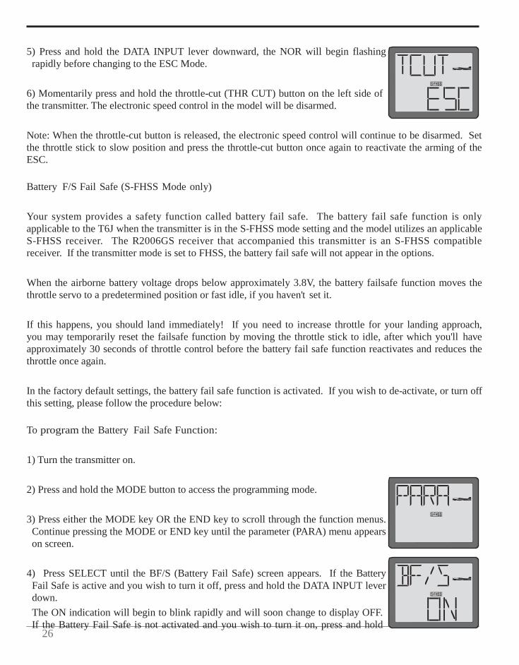
5) Press and hold the DATA INPUT lever downward, the NOR will begin flashing
rapidly before changing to the ESC Mode.
6) Momentarily press and hold the throttle-cut (THR CUT) button on the left side of the transmitter. The electronic speed control in the model will be disarmed.
Note: When the throttle-cut button is released, the electronic speed control will continue to be disarmed. Set the throttle stick to slow position and press the throttle-cut button once again to reactivate the arming of the ESC.
Battery F/S Fail Safe (S-FHSS Mode only)
Your system provides a safety function called battery fail safe. The battery fail safe function is only applicable to the T6J when the transmitter is in the S-FHSS mode setting and the model utilizes an applicable S-FHSS receiver. The R2006GS receiver that accompanied this transmitter is an S-FHSS compatible receiver. If the transmitter mode is set to FHSS, the battery fail safe will not appear in the options.
When the airborne battery voltage drops below approximately 3.8V, the battery failsafe function moves the throttle servo to a predetermined position or fast idle, if you haven't set it.
If this happens, you should land immediately! If you need to increase throttle for your landing approach, you may temporarily reset the failsafe function by moving the throttle stick to idle, after which you'll have approximately 30 seconds of throttle control before the battery fail safe function reactivates and reduces the throttle once again.
In the factory default settings, the battery fail safe function is activated. If you wish to de-activate, or turn off this setting, please follow the procedure below:
To program the Battery Fail Safe Function:
1) Turn the transmitter on.
2) Press and hold the MODE button to access the programming mode.
3) Press either the MODE key OR the END key to scroll through the function menus. Continue pressing the MODE or END key until the parameter (PARA) menu appears on screen.
4) Press SELECT until the BF/S (Battery Fail Safe) screen appears. If the Battery Fail Safe is active and you wish to turn it off, press and hold the DATA INPUT lever down. The ON indication will begin to blink rapidly and will soon change to display OFF. If the Battery Fail Safe is not activated and you wish to turn it on, press and hold
2
the DATA INPUT lever upward. The OFF indication will begin to blink rapidly and will soon change to display ON.
5) Press and hold the END button to exit the programming menu.
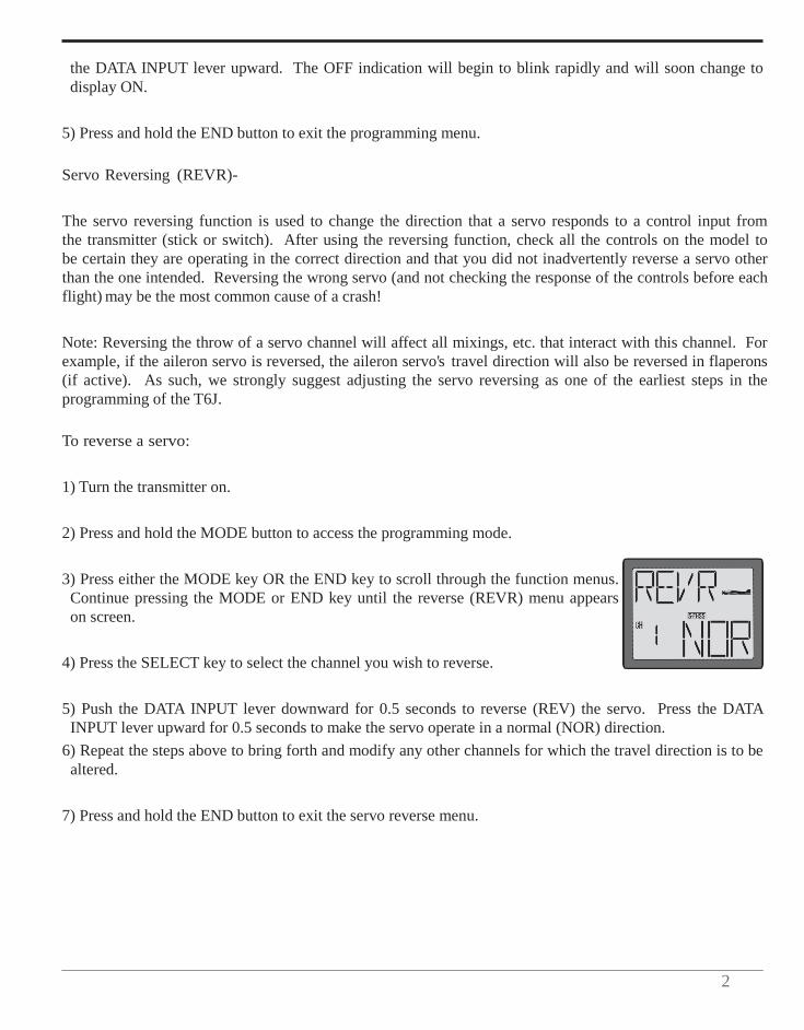
Servo Reversing (REVR)-
The servo reversing function is used to change the direction that a servo responds to a control input from the transmitter (stick or switch). After using the reversing function, check all the controls on the model to be certain they are operating in the correct direction and that you did not inadvertently reverse a servo other than the one intended. Reversing the wrong servo (and not checking the response of the controls before each flight) may be the most common cause of a crash!
Note: Reversing the throw of a servo channel will affect all mixings, etc. that interact with this channel. For example, if the aileron servo is reversed, the aileron servo's travel direction will also be reversed in flaperons (if active). As such, we strongly suggest adjusting the servo reversing as one of the earliest steps in the programming of the T6J.
To reverse a servo:
1) Turn the transmitter on.
2) Press and hold the MODE button to access the programming mode.
3) Press either the MODE key OR the END key to scroll through the function menus. Continue pressing the MODE or END key until the reverse (REVR) menu appears on screen.
4) Press the SELECT key to select the channel you wish to reverse.
5) Push the DATA INPUT lever downward for 0.5 seconds to reverse (REV) the servo. Press the DATA INPUT lever upward for 0.5 seconds to make the servo operate in a normal (NOR) direction.
6) Repeat the steps above to bring forth and modify any other channels for which the travel direction is to be altered.
7) Press and hold the END button to exit the servo reverse menu.
28
Dual Rates/Exponential Settings-
Dual Rates/Exponential Settings vary slightly between the airplane (ACRO) mode and the helicopter (HELI) mode. As such, the information pertaining to these functions will be separated into ACRO and HELI sections below. Please adhere to the section that pertains to the model for which you are programming the T6J transmitter.
ACRO Dual Rates/Exponential Information:
Dual Rates (ACRO): Commonly abbreviated as "DIR", dual rate is the ability to change the travel distance of a servo or servos, affecting the overall travel of the servo(s). Thus, decreasing the percentage value for a given servo will reduce the travel amount of the channel respectively. For example, if the elevator of the aircraft travels 1/2” at the high rate and maximum stick input, and a value of 50% is input for the low rate, when the switch is moved to the low rate position, the servo moves exactly half as far per stick position. Following this example, if the elevator control input is all the way up, the maximum travel is now 1/4” The T6J transmitter offers dual rates on the aileron, elevator and rudder channels. The dual rates are assignable to any of the switches on the transmitter and all are simultaneously activated by the dual rate switch selected.
The amount of travel decrease for each control may be set between 0% and 140% of the values set for the end points (explained in End Point Adjustment on page 33).
Note: It is possible to set a dual rate value to zero, thus causing no response from that channel when the dual rates are activated. If the dual rates are inadvertently set to zero, a crash could result.
Note: When performing the initial model setup, the EPA's should be set prior to setting the dual rates. When setting the EPA's for the first time on a new model, the dual rates should be set to 100%.
D/R Dual Rate Settings (ACRO)
To select the Switch/position to control the dual rates:
Prior to programming the dual rates for the aileron, elevator or rudder channels, we suggest selection of the switch that will be utilized to control the rate settings.
1) Turn the transmitter on.
2) Press and hold the MODE button to access the programming mode.
3) Press either the MODE key OR the END key to scroll through the function menus. Each time one of the aforementioned keys is pressed the menu will change accordingly. Continue pressing the MODE or END
2
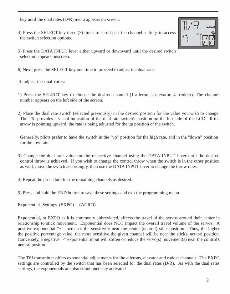
key until the dual rates (D/R) menu appears on screen.
4) Press the SELECT key three (3) times to scroll past the channel settings to access the switch selection options.
5) Press the DATA INPUT lever either upward or downward until the desired switch selection appears onscreen.
6) Next, press the SELECT key one time to proceed to adjust the dual rates.
To adjust the dual rates:
1) Press the SELECT key to choose the desired channel (1-aileron, 2-elevator, 4- rudder). The channel number appears on the left side of the screen.
2) Place the dual rate switch (selected previously) in the desired position for the value you wish to change. The T6J provides a visual indication of the dual rate switch's position on the left side of the LCD. If the arrow is pointing upward, the rate is being adjusted for the up position of the switch.
Generally, pilots prefer to have the switch in the "up" position for the high rate, and in the "down" position for the low rate.
3) Change the dual rate value for the respective channel using the DATA INPUT lever until the desired control throw is achieved. If you wish to change the control throw when the switch is in the other position as well, move the switch accordingly, then use the DATA INPUT lever to change the throw rates.
4) Repeat the procedure for the remaining channels as desired.
5) Press and hold the END button to save these settings and exit the programming menu.
Exponential Settings (EXPO) – (ACRO)
Exponential, or EXPO as it is commonly abbreviated, affects the travel of the servos around their center in relationship to stick movement. Exponential does NOT impact the overall travel volume of the servos. A positive exponential "+" increases the sensitivity near the center (neutral) stick position. Thus, the higher the positive percentage value, the more sensitive the given channel will be near the stick's neutral position. Conversely, a negative "-" exponential input will soften or reduce the servo(s) movement(s) near the control's neutral position.
The T6J transmitter offers exponential adjustments for the ailerons, elevator and rudder channels. The EXPO settings are controlled by the switch that has been selected for the dual rates (D/R). As with the dual rates settings, the exponentials are also simultaneously activated.
30
The amount of travel decrease for each control may be set between -100% and +100% of the values set for the end points (explained in End Point Adjustment on page 33).
To set the exponentials:
1) Turn the transmitter on.
2) Press and hold the MODE button to access the programming mode.
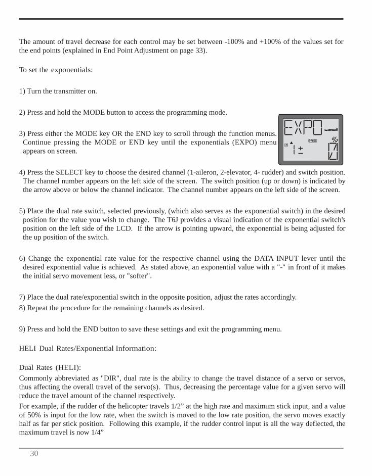
3) Press either the MODE key OR the END key to scroll through the function menus. Continue pressing the MODE or END key until the exponentials (EXPO) menu appears on screen.
4) Press the SELECT key to choose the desired channel (1-aileron, 2-elevator, 4- rudder) and switch position. The channel number appears on the left side of the screen. The switch position (up or down) is indicated by the arrow above or below the channel indicator. The channel number appears on the left side of the screen.
5) Place the dual rate switch, selected previously, (which also serves as the exponential switch) in the desired position for the value you wish to change. The T6J provides a visual indication of the exponential switch's position on the left side of the LCD. If the arrow is pointing upward, the exponential is being adjusted for the up position of the switch.
6) Change the exponential rate value for the respective channel using the DATA INPUT lever until the desired exponential value is achieved. As stated above, an exponential value with a "-" in front of it makes the initial servo movement less, or "softer".
7) Place the dual rate/exponential switch in the opposite position, adjust the rates accordingly. 8) Repeat the procedure for the remaining channels as desired.
9) Press and hold the END button to save these settings and exit the programming menu.
HELI Dual Rates/Exponential Information:
Dual Rates (HELI): Commonly abbreviated as "DIR", dual rate is the ability to change the travel distance of a servo or servos, thus affecting the overall travel of the servo(s). Thus, decreasing the percentage value for a given servo will reduce the travel amount of the channel respectively. For example, if the rudder of the helicopter travels 1/2” at the high rate and maximum stick input, and a value of 50% is input for the low rate, when the switch is moved to the low rate position, the servo moves exactly half as far per stick position. Following this example, if the rudder control input is all the way deflected, the maximum travel is now 1/4”
3
The T6J transmitter offers dual rates on the aileron, elevator and rudder channels. The dual rates are assignable to switches A, B or IDL on the transmitter and are simultaneously activated by the dual rate switch selected.
The amount of travel decrease for each control may be set between 0% and 140% of the values set for the end points (explained in End Point Adjustment on page 33).
Note: It is possible to set a dual rate value to zero, thus causing no response from that channel when the dual rates are activated. If the dual rates are inadvertently set to zero, a crash could result.
Note: When performing initial model setup, the EPA's should be set prior to setting the dual rates. When setting the EPA's for the first time on a new model, the dual rates should be set to 100%.
Dual Rate Settings (HELI)
To select the Switch/position to control the dual rates:
Prior to programming the dual rates for the aileron, elevator or rudder channels, we suggest selection of the switch that will be utilized to control the rate settings.
1) Turn the transmitter on.
2) Press and hold the MODE button to access the programming mode. An audible double beep will be heard and the default screen will change accordingly.
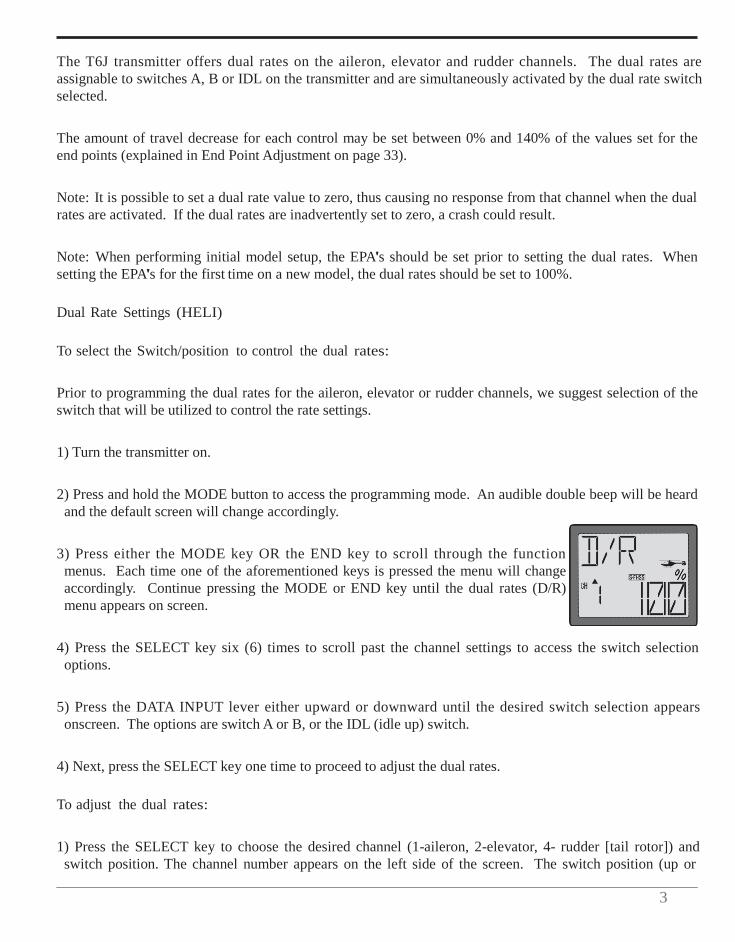
3) Press either the MODE key OR the END key to scroll through the function menus. Each time one of the aforementioned keys is pressed the menu will change accordingly. Continue pressing the MODE or END key until the dual rates (D/R) menu appears on screen.
4) Press the SELECT key six (6) times to scroll past the channel settings to access the switch selection options.
5) Press the DATA INPUT lever either upward or downward until the desired switch selection appears onscreen. The options are switch A or B, or the IDL (idle up) switch.
4) Next, press the SELECT key one time to proceed to adjust the dual rates.
To adjust the dual rates:
1) Press the SELECT key to choose the desired channel (1-aileron, 2-elevator, 4- rudder [tail rotor]) and switch position. The channel number appears on the left side of the screen. The switch position (up or
32
down) is indicated by the flashing arrow above or below the channel indicator.
2) Observing the up/down switch position indicator, change the dual rate value for the respective channel using the DATA INPUT lever until the desired control throw is achieved.
Again, if the arrow is pointing upward, the rate is being adjusted for the up position of the switch.
Generally, pilots prefer to have the switch in the "up" position for the high rate, and in the "down" position for the low rate.
3) Press the SELECT key to change the switch position indicator to the opposite position.
Note: This assumes that the modeler has adjusted the up switch position. If the down switch position was adjusted, the SELECT key will move to the next channel or switch selection menu as the case may be.
4) Change the dual rate value for the respective channel using the DATA INPUT lever until the desired control throw is achieved.
5) Repeat the procedure for the remaining channels and switch positions as desired.
6) Press and hold the END button to save these settings and exit the programming menu.
Exponential Settings (EXPO) - HELI
Exponential, or EXPO as it is commonly abbreviated, affects the travel of the servos around their center in relationship to stick movement. Exponential does NOT impact the overall travel volume of the servos. A positive exponential "+" increases the sensitivity near the center (neutral) stick position. Thus, the higher the positive percentage value, the more sensitive the given channel will be near the stick's neutral position. Conversely, a negative "-" exponential input will soften or reduce the servo(s) movement(s) near the control's neutral position.
The T6J transmitter offers exponential adjustments for the ailerons, elevator and rudder channels. The EXPO settings are controlled by the switch that has been selected for the dual rates (D/R). As with the dual rates settings, the exponentials are also simultaneously activated.
The amount of travel decrease for each control may be set between -100% and +100% of the values set for the end points (explained in End Point Adjustment on page ??).
To set the exponentials:
1) Turn the transmitter on.
3
2) Press and hold the MODE button to access the programming mode.
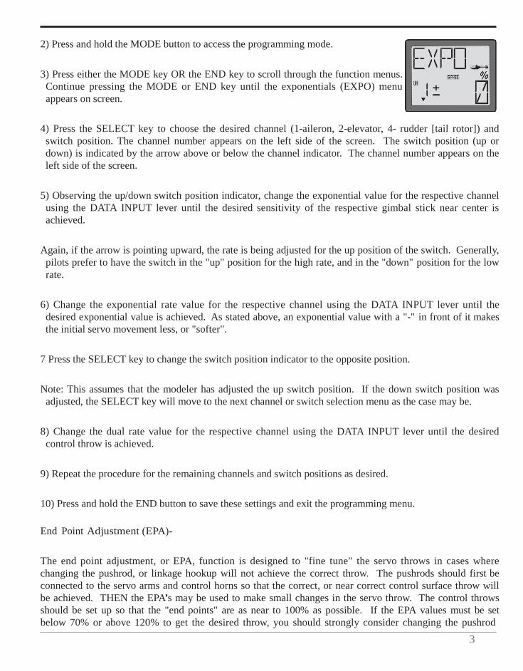
3) Press either the MODE key OR the END key to scroll through the function menus. Continue pressing the MODE or END key until the exponentials (EXPO) menu appears on screen.
4) Press the SELECT key to choose the desired channel (1-aileron, 2-elevator, 4- rudder [tail rotor]) and switch position. The channel number appears on the left side of the screen. The switch position (up or down) is indicated by the arrow above or below the channel indicator. The channel number appears on the left side of the screen.
5) Observing the up/down switch position indicator, change the exponential value for the respective channel using the DATA INPUT lever until the desired sensitivity of the respective gimbal stick near center is achieved.
Again, if the arrow is pointing upward, the rate is being adjusted for the up position of the switch. Generally, pilots prefer to have the switch in the "up" position for the high rate, and in the "down" position for the low rate.
6) Change the exponential rate value for the respective channel using the DATA INPUT lever until the desired exponential value is achieved. As stated above, an exponential value with a "-" in front of it makes the initial servo movement less, or "softer".
7 Press the SELECT key to change the switch position indicator to the opposite position.
Note: This assumes that the modeler has adjusted the up switch position. If the down switch position was adjusted, the SELECT key will move to the next channel or switch selection menu as the case may be.
8) Change the dual rate value for the respective channel using the DATA INPUT lever until the desired control throw is achieved.
9) Repeat the procedure for the remaining channels and switch positions as desired.
10) Press and hold the END button to save these settings and exit the programming menu.
End Point Adjustment (EPA)-
The end point adjustment, or EPA, function is designed to "fine tune" the servo throws in cases where changing the pushrod, or linkage hookup will not achieve the correct throw. The pushrods should first be connected to the servo arms and control horns so that the correct, or near correct control surface throw will be achieved. THEN the EPA's may be used to make small changes in the servo throw. The control throws should be set up so that the "end points" are as near to 100% as possible. If the EPA values must be set below 70% or above 120% to get the desired throw, you should strongly consider changing the pushrod
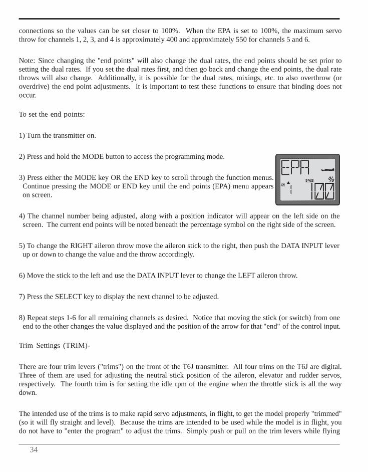
34
connections so the values can be set closer to 100%. When the EPA is set to 100%, the maximum servo throw for channels 1, 2, 3, and 4 is approximately 400 and approximately 550 for channels 5 and 6.
Note: Since changing the "end points" will also change the dual rates, the end points should be set prior to setting the dual rates. If you set the dual rates first, and then go back and change the end points, the dual rate throws will also change. Additionally, it is possible for the dual rates, mixings, etc. to also overthrow (or overdrive) the end point adjustments. It is important to test these functions to ensure that binding does not occur.
To set the end points:
1) Turn the transmitter on.
2) Press and hold the MODE button to access the programming mode.
3) Press either the MODE key OR the END key to scroll through the function menus. Continue pressing the MODE or END key until the end points (EPA) menu appears on screen.
4) The channel number being adjusted, along with a position indicator will appear on the left side on the screen. The current end points will be noted beneath the percentage symbol on the right side of the screen.
5) To change the RIGHT aileron throw move the aileron stick to the right, then push the DATA INPUT lever up or down to change the value and the throw accordingly.
6) Move the stick to the left and use the DATA INPUT lever to change the LEFT aileron throw.
7) Press the SELECT key to display the next channel to be adjusted.
8) Repeat steps 1-6 for all remaining channels as desired. Notice that moving the stick (or switch) from one end to the other changes the value displayed and the position of the arrow for that "end" of the control input.
Trim Settings (TRIM)-
There are four trim levers ("trims") on the front of the T6J transmitter. All four trims on the T6J are digital. Three of them are used for adjusting the neutral stick position of the aileron, elevator and rudder servos, respectively. The fourth trim is for setting the idle rpm of the engine when the throttle stick is all the way down.
The intended use of the trims is to make rapid servo adjustments, in flight, to get the model properly "trimmed" (so it will fly straight and level). Because the trims are intended to be used while the model is in flight, you do not have to "enter the program" to adjust the trims. Simply push or pull on the trim levers while flying
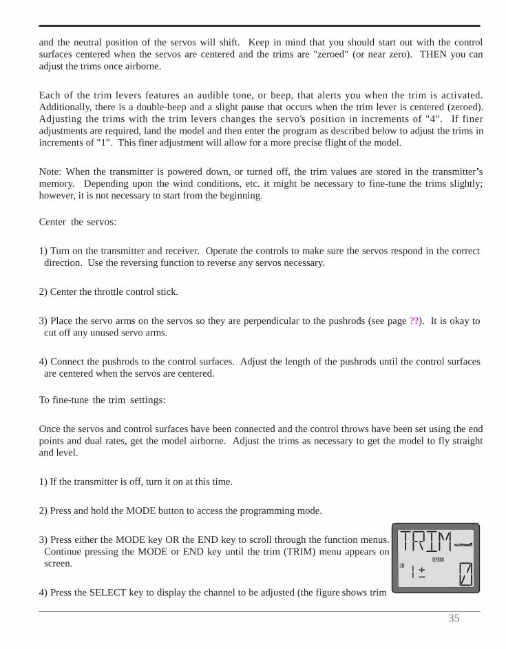
35
and the neutral position of the servos will shift. Keep in mind that you should start out with the control surfaces centered when the servos are centered and the trims are "zeroed" (or near zero). THEN you can adjust the trims once airborne.
Each of the trim levers features an audible tone, or beep, that alerts you when the trim is activated. Additionally, there is a double-beep and a slight pause that occurs when the trim lever is centered (zeroed). Adjusting the trims with the trim levers changes the servo's position in increments of "4". If finer adjustments are required, land the model and then enter the program as described below to adjust the trims in increments of "1". This finer adjustment will allow for a more precise flight of the model.
Note: When the transmitter is powered down, or turned off, the trim values are stored in the transmitter's memory. Depending upon the wind conditions, etc. it might be necessary to fine-tune the trims slightly; however, it is not necessary to start from the beginning.
Center the servos:
1) Turn on the transmitter and receiver. Operate the controls to make sure the servos respond in the correct direction. Use the reversing function to reverse any servos necessary.
2) Center the throttle control stick.
3) Place the servo arms on the servos so they are perpendicular to the pushrods (see page ??). It is okay to cut off any unused servo arms.
4) Connect the pushrods to the control surfaces. Adjust the length of the pushrods until the control surfaces are centered when the servos are centered.
To fine-tune the trim settings:
Once the servos and control surfaces have been connected and the control throws have been set using the end points and dual rates, get the model airborne. Adjust the trims as necessary to get the model to fly straight and level.
1) If the transmitter is off, turn it on at this time.
2) Press and hold the MODE button to access the programming mode.
3) Press either the MODE key OR the END key to scroll through the function menus. Continue pressing the MODE or END key until the trim (TRIM) menu appears on screen.
4) Press the SELECT key to display the channel to be adjusted (the figure shows trim
36
adjustments for CH1).
5) Adjust the trim using the DATA INPUT lever. Note that initially, the values change in increments of "1", but if the DATA INPUT lever is held long enough the values will change more rapidly.
6) Press the SELECT key to bring forth the trim values for the remaining channels. To change the values for these channels, repeat step 3 above for each channel that requires trim adjustments.
7) Press and hold the END button to exit the programming mode.
8) Verify that you are satisfied with the trim settings by flying the model once again.
Note: it is generally best to fine-tune the trims of your model on a very calm day as windy conditions will impact the flight characteristics of the model.
To view the trim settings:
Once the model has been flown and the trims are adjusted accordingly, it is possible to easily and rapidly view the trim setting adjustments.
1) Turn the transmitter on. If the transmitter is already on, ensure that it is in the default display mode.
2) With the home page displayed, press and hold the END key. The T6J will then scroll through the trim settings for each of the respective channels. The channel is indicated on the left side of the screen; whereas the trim input will be located on the right side of the LCD.
Sub-Trims (STRM)-
The sub-trims are generally used to off-set the center position of the servos if you are unable to achieve perfect mechanical linkages. The T6J transmitter allows for sub-trim adjustments on all six channels. Rather than inputting extremely high sub-trim values, we suggest adjusting the respective control linkages first. Ensure that the linkages are as perfect as possible prior to adjusting the sub-trims. Extremely high sub-trim values will significantly impact the travel of the respective servo(s).
To adjust the Sub-Trim settings:
1) Turn the transmitter on.
2) Press and hold the MODE button to access the programming mode.
3) Press either the MODE key OR the END key to scroll through the function menus. Each time one of the aforementioned keys is pressed the menu will change accordingly. Continue pressing the MODE or END

37
key until the sub-trims (STRM) menu appears on screen.
4) Press the SELECT button to choose the channel for which you wish to adjust the sub-trims. The channel is indicated on the left side of the LCD screen.
5) Press the DATA INPUT lever to change the sub-trim value for the selected channel. Please note the travel direction of the sub-trim adjustment is indicated by a flashing "+" or a "-"on the left side of the LCD next to the channel indication. The travel value of the sub-trim is indicated by a flashing numeric value on the right side of the screen.
6) Repeat steps 1-3 for all channels as desired.
Note: If programming a helicopter (HELI) model, please skip ahead to the section entitled "Heli Only Programming”, the information that follows is only applicable to airplane (ACRO) models.
Programmable Mix 1 and 2 (PMX 1 and PMIX 2) - (ACRO only)
Unlike the "wing mixing" function (explained later) where the channels to be mixed are factory-set, the T6J also contains two programmable mixes where you, the pilot, determine the channels to be mixed. Programmable mixes could be used to correct unwanted flight tendencies (by mixing rudder to aileron, or aileron to rudder for example).
Note: Programmable Mixes 1 and 2 are programmed in the exact same manner and methodology. As such, we will only explain how to program one of the mixes. Should a second mix be necessary, follow this procedure once again for the second mix accordingly.
To set up a programmable mix:
1) Turn the transmitter on.
2) Press and hold the MODE button to access the programming mode.
3) Press either the MODE key OR the END key to scroll through the function menus. Each time one of the aforementioned keys is pressed the menu will change accordingly. Continue pressing the MODE or END key until the first programmable mix (PMX 1) menu appears on screen.
4) Push the DATA INPUT lever upward for 0.5 seconds. This will cause the INH display to flash rapidly before changing to a flashing ON display.
5) Press the SELECT key twice to call the screen for selecting channels to control "MAS" (Master) mixing. Then select the channel by pushing DATA INPUT lever.
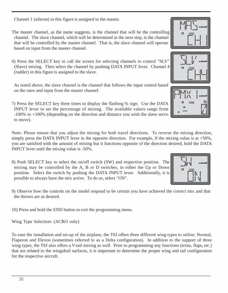
38
Channel 1 (aileron) in this figure is assigned to the master.
The master channel, as the name suggests, is the channel that will be the controlling channel. The slave channel, which will be determined in the next step, is the channel that will be controlled by the master channel. That is, the slave channel will operate based on input from the master channel.
6) Press the SELECT key to call the screen for selecting channels to control "SLV" (Slave) mixing. Then select the channel by pushing DATA INPUT lever. Channel 4 (rudder) in this figure is assigned to the slave.
As noted above, the slave channel is the channel that follows the input control based on the rates and input from the master channel.
7) Press the SELECT key three times to display the flashing % sign. Use the DATA INPUT lever to set the percentage of mixing. The available values range from -100% to +100% (depending on the direction and distance you wish the slave servo to move).
Note: Please ensure that you adjust the mixing for both travel directions. To reverse the mixing direction, simply press the DATA INPUT lever in the opposite direction. For example, if the mixing value is at +50%, you are satisfied with the amount of mixing but it functions opposite of the direction desired, hold the DATA INPUT lever until the mixing value is -50%.
8) Push SELECT key to select the on/off switch (SW) and respective position. The mixing may be controlled by the A, B or D switches, in either the Up or Down position. Select the switch by pushing the DATA INPUT lever. Additionally, it is possible to always have the mix active. To do so, select "ON".
9) Observe how the controls on the model respond to be certain you have achieved the correct mix and that the throws are as desired.
10) Press and hold the END button to exit the programming menu.
Wing Type Selection- (ACRO only)
To ease the installation and set-up of the airplane, the T6J offers three different wing types to utilize: Normal, Flaperon and Elevon (sometimes referred to as a Delta configuration). In addition to the support of three wing types, the T6J also offers a V-tail mixing as well. Prior to programming any functions (trims, flaps, etc.) that are related to the wingsItail surfaces, it is important to determine the proper wing and tail configuration for the respective aircraft.
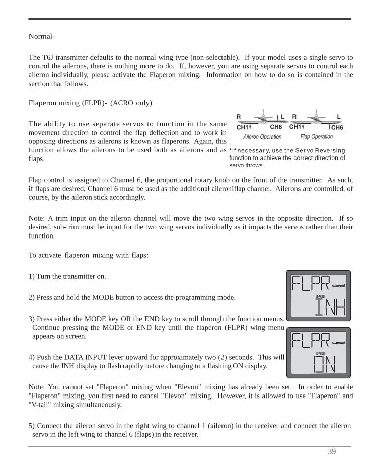
39
Normal-
The T6J transmitter defaults to the normal wing type (non-selectable). If your model uses a single servo to control the ailerons, there is nothing more to do. If, however, you are using separate servos to control each aileron individually, please activate the Flaperon mixing. Information on how to do so is contained in the section that follows.
Flaperon mixing (FLPR)- (ACRO only)
The ability to use separate servos to function in the same movement direction to control the flap deflection and to work in opposing directions as ailerons is known as flaperons. Again, this function allows the ailerons to be used both as ailerons and as flaps.
*If necessar y, use the Ser vo Reversing function to achieve the correct direction of servo throws.
Flap control is assigned to Channel 6, the proportional rotary knob on the front of the transmitter. As such, if flaps are desired, Channel 6 must be used as the additional aileronIflap channel. Ailerons are controlled, of course, by the aileron stick accordingly.
Note: A trim input on the aileron channel will move the two wing servos in the opposite direction. If so desired, sub-trim must be input for the two wing servos individually as it impacts the servos rather than their function.
To activate flaperon mixing with flaps:
1) Turn the transmitter on.
2) Press and hold the MODE button to access the programming mode.
3) Press either the MODE key OR the END key to scroll through the function menus. Continue pressing the MODE or END key until the flaperon (FLPR) wing menu appears on screen.
4) Push the DATA INPUT lever upward for approximately two (2) seconds. This will cause the INH display to flash rapidly before changing to a flashing ON display.
Note: You cannot set "Flaperon" mixing when "Elevon" mixing has already been set. In order to enable "Flaperon" mixing, you first need to cancel "Elevon" mixing. However, it is allowed to use "Flaperon" and "V-tail" mixing simultaneously.
5) Connect the aileron servo in the right wing to channel 1 (aileron) in the receiver and connect the aileron servo in the left wing to channel 6 (flaps) in the receiver.

40
6) If you need to set aileron differential, press the SELECT key to display the flashing
"%" sign. Use the DATA INPUT lever to set the percentage of aileron differential from -100% to +100%.
The "-"direction indicates decreasing amount of movement toward the upward from the aileron surface, while "+" direction indicates decreasing amount of movement toward the downward from the aileron surface.
Aileron differential adjusts the travel of each aileron. Generally it is used to create a larger upward aileron travel (reducing the amount of downward aileron travel) to create a more axial roll rate; reducing unwanted yaw of the aircraft.
7) Once the mix has been activated, move the servos to their full extremes to make certain they are not overdriving the controls. If necessary, adjust the linkages to achieve the correct control throws.
8) Press and hold the END key to exit the programming menu.
To activate flaperon mixing without flaps:
1) Turn the transmitter on.
2) Press and hold the MODE button to access the programming mode.
3) Press either the MODE key OR the END key to scroll through the function menus. Continue pressing the MODE or END key until the flaperon (FLPR) wing menu appears on screen.
4) Push the DATA INPUT lever upward for approximately two (2) seconds. This will cause the INH display to flash rapidly before changing to a flashing ON display.
5) Connect the aileron servo in the right wing to channel 1 (aileron) in the receiver and connect the aileron servo in the left wing to an unused channel from 3-6, depending upon the model aircraft.
Note: When using a channel other than channel 6, other programming options and functionality will be affected accordingly. For example, channel 3 is used as the throttle control in Futaba transmitters. If channel 3 is selected as the left aileron channel, it will not be operational from the throttle stick, only the aileron.
6) If you need to set aileron differential, press the SELECT key to display the flashing "%" sign. Use the DATA INPUT lever to set the percentage of aileron differential from -100% to +100%.
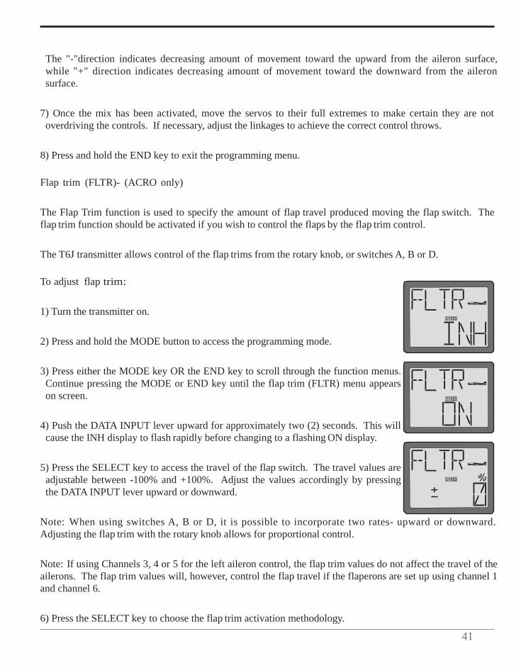
41
The "-"direction indicates decreasing amount of movement toward the upward from the aileron surface, while "+" direction indicates decreasing amount of movement toward the downward from the aileron surface.
7) Once the mix has been activated, move the servos to their full extremes to make certain they are not overdriving the controls. If necessary, adjust the linkages to achieve the correct control throws.
8) Press and hold the END key to exit the programming menu.
Flap trim (FLTR)- (ACRO only)
The Flap Trim function is used to specify the amount of flap travel produced moving the flap switch. The flap trim function should be activated if you wish to control the flaps by the flap trim control.
The T6J transmitter allows control of the flap trims from the rotary knob, or switches A, B or D.
To adjust flap trim:
1) Turn the transmitter on.
2) Press and hold the MODE button to access the programming mode.
3) Press either the MODE key OR the END key to scroll through the function menus. Continue pressing the MODE or END key until the flap trim (FLTR) menu appears on screen.
4) Push the DATA INPUT lever upward for approximately two (2) seconds. This will cause the INH display to flash rapidly before changing to a flashing ON display.
5) Press the SELECT key to access the travel of the flap switch. The travel values are adjustable between -100% and +100%. Adjust the values accordingly by pressing the DATA INPUT lever upward or downward.
Note: When using switches A, B or D, it is possible to incorporate two rates- upward or downward. Adjusting the flap trim with the rotary knob allows for proportional control.
Note: If using Channels 3, 4 or 5 for the left aileron control, the flap trim values do not affect the travel of the ailerons. The flap trim values will, however, control the flap travel if the flaperons are set up using channel 1 and channel 6.
6) Press the SELECT key to choose the flap trim activation methodology.
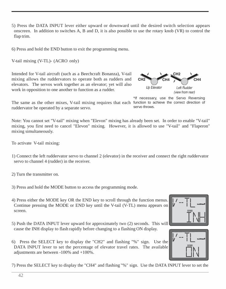
42
5) Press the DATA INPUT lever either upward or downward until the desired switch selection appears onscreen. In addition to switches A, B and D, it is also possible to use the rotary knob (VR) to control the flap trim.
6) Press and hold the END button to exit the programming menu.
V-tail mixing (V-TL)- (ACRO only)
Intended for V-tail aircraft (such as a Beechcraft Bonanza), V-tail mixing allows the ruddervators to operate both as rudders and elevators. The servos work together as an elevator; yet will also work in opposition to one another to function as a rudder.
The same as the other mixes, V-tail mixing requires that each ruddervator be operated by a separate servo.
*If necessary, use the Servo Reversing function to achieve the correct direction of servo throws.
Note: You cannot set "V-tail" mixing when "Elevon" mixing has already been set. In order to enable "V-tail" mixing, you first need to cancel "Elevon" mixing. However, it is allowed to use "V-tail" and "Flaperon" mixing simultaneously.
To activate V-tail mixing:
1) Connect the left ruddervator servo to channel 2 (elevator) in the receiver and connect the right ruddervator servo to channel 4 (rudder) in the receiver.
2) Turn the transmitter on.
3) Press and hold the MODE button to access the programming mode.
4) Press either the MODE key OR the END key to scroll through the function menus. Continue pressing the MODE or END key until the V-tail (V-TL) menu appears on screen.
5) Push the DATA INPUT lever upward for approximately two (2) seconds. This will cause the INH display to flash rapidly before changing to a flashing ON display.
6) Press the SELECT key to display the "CH2" and flashing "%" sign. Use the DATA INPUT lever to set the percentage of elevator travel rates. The available adjustments are between -100% and +100%.
7) Press the SELECT key to display the "CH4" and flashing "%" sign. Use the DATA INPUT lever to set the

43
percentage of rudder travel rates. The available adjustments are between -100% and +100%.
8) Once this mix has been activated, move the servos to their full extremes to make certain they are not overdriving the controls. If necessary, adjust the linkages to achieve the correct control throws.
Note: It is important to ensure that no binding occurs when providing full elevator and full rudder inputs. This will maximize the inputs from both channels and provide you with the worst-case scenario.
9) Press and hold the END button to exit the programming menu.
Elevon mixing (ELVN)- (ACRO only)
Intended for tailless, "flying wing" models such as delta wings and flying wings, elevon mixing mixes channel 1 (aileron) to channel 2 (elevator) allowing the elevons to operate in unison (as elevators) or in opposition (as ailerons). This function requires that each elevon be operated by a separate servo.
Note: The Elevon function can not be utilized when either the V-Tail or Flaperons are active. If either V-tail or flaperons are activated, it will not be possible to activate the elevon mixing function.
To activate elevon mixing:
*If necessary, use the Servo Reversing function to achieve the correct direction of servo throws.
CH1 CH2
1) Connect the servo in the right wing channel to channel 2 (elevator) in the receiver and connect the servo in the left wing to channel 1 (aileron) in the receiver.
2) Turn the transmitter on.
3) Press and hold the MODE button to access the programming mode.
4) Press either the MODE key OR the END key to scroll through the function menus. Continue pressing the MODE or END key until the elevon (ELVN) menu appears on screen.
You cannot set "Elevon" mixing when "Flaperon" or "V-TL" mixing has already been set. In order to enable "Elevon" mixing, you first need to cancel both "Flaperon" and "V-tail" mixing.
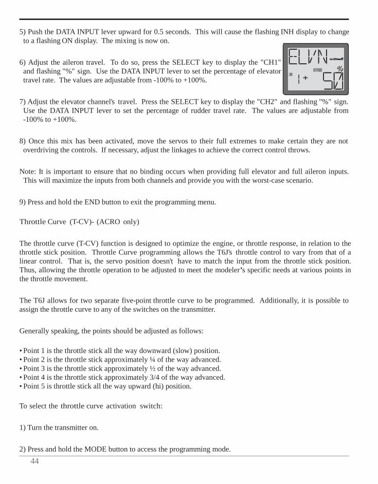
44
5) Push the DATA INPUT lever upward for 0.5 seconds. This will cause the flashing INH display to change
to a flashing ON display. The mixing is now on.
6) Adjust the aileron travel. To do so, press the SELECT key to display the "CH1" and flashing "%" sign. Use the DATA INPUT lever to set the percentage of elevator travel rate. The values are adjustable from -100% to +100%.
7) Adjust the elevator channel's travel. Press the SELECT key to display the "CH2" and flashing "%" sign. Use the DATA INPUT lever to set the percentage of rudder travel rate. The values are adjustable from -100% to +100%.
8) Once this mix has been activated, move the servos to their full extremes to make certain they are not overdriving the controls. If necessary, adjust the linkages to achieve the correct control throws.
Note: It is important to ensure that no binding occurs when providing full elevator and full aileron inputs. This will maximize the inputs from both channels and provide you with the worst-case scenario.
9) Press and hold the END button to exit the programming menu.
Throttle Curve (T-CV)- (ACRO only)
The throttle curve (T-CV) function is designed to optimize the engine, or throttle response, in relation to the throttle stick position. Throttle Curve programming allows the T6J's throttle control to vary from that of a linear control. That is, the servo position doesn't have to match the input from the throttle stick position. Thus, allowing the throttle operation to be adjusted to meet the modeler's specific needs at various points in the throttle movement.
The T6J allows for two separate five-point throttle curve to be programmed. Additionally, it is possible to assign the throttle curve to any of the switches on the transmitter.
Generally speaking, the points should be adjusted as follows:
• Point 1 is the throttle stick all the way downward (slow) position. • Point 2 is the throttle stick approximately ¼ of the way advanced. • Point 3 is the throttle stick approximately ½ of the way advanced. • Point 4 is the throttle stick approximately 3/4 of the way advanced. • Point 5 is throttle stick all the way upward (hi) position.
To select the throttle curve activation switch:
1) Turn the transmitter on.
2) Press and hold the MODE button to access the programming mode.
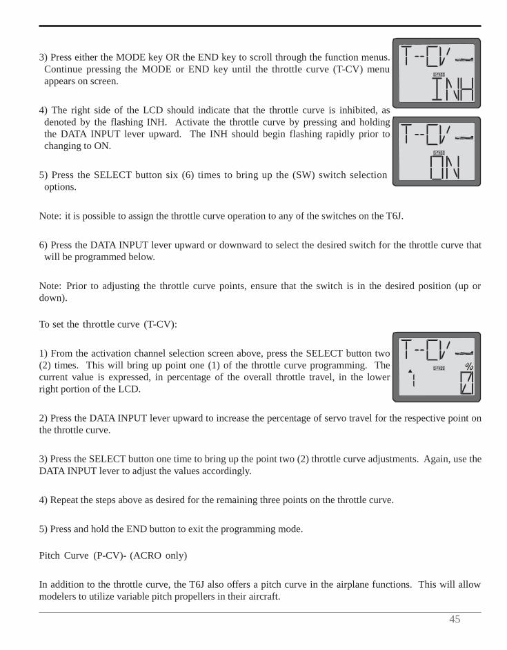
45
3) Press either the MODE key OR the END key to scroll through the function menus. Continue pressing the MODE or END key until the throttle curve (T-CV) menu appears on screen.
4) The right side of the LCD should indicate that the throttle curve is inhibited, as denoted by the flashing INH. Activate the throttle curve by pressing and holding the DATA INPUT lever upward. The INH should begin flashing rapidly prior to changing to ON.
5) Press the SELECT button six (6) times to bring up the (SW) switch selection options.
Note: it is possible to assign the throttle curve operation to any of the switches on the T6J.
6) Press the DATA INPUT lever upward or downward to select the desired switch for the throttle curve that will be programmed below.
Note: Prior to adjusting the throttle curve points, ensure that the switch is in the desired position (up or down).
To set the throttle curve (T-CV):
1) From the activation channel selection screen above, press the SELECT button two (2) times. This will bring up point one (1) of the throttle curve programming. The current value is expressed, in percentage of the overall throttle travel, in the lower right portion of the LCD.
2) Press the DATA INPUT lever upward to increase the percentage of servo travel for the respective point on the throttle curve.
3) Press the SELECT button one time to bring up the point two (2) throttle curve adjustments. Again, use the DATA INPUT lever to adjust the values accordingly.
4) Repeat the steps above as desired for the remaining three points on the throttle curve.
5) Press and hold the END button to exit the programming mode.
Pitch Curve (P-CV)- (ACRO only)
In addition to the throttle curve, the T6J also offers a pitch curve in the airplane functions. This will allow modelers to utilize variable pitch propellers in their aircraft.
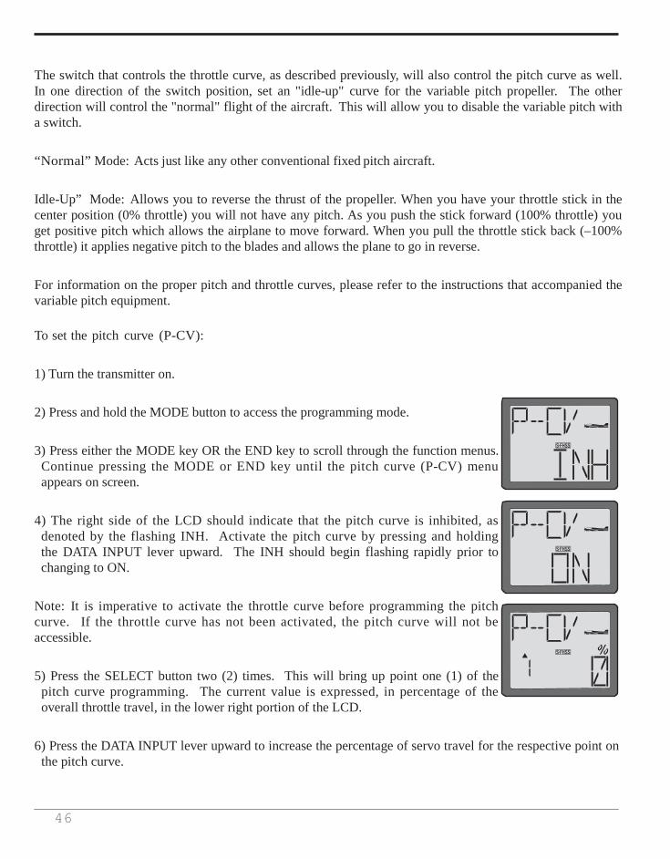
46
The switch that controls the throttle curve, as described previously, will also control the pitch curve as well. In one direction of the switch position, set an "idle-up" curve for the variable pitch propeller. The other direction will control the "normal" flight of the aircraft. This will allow you to disable the variable pitch with a switch.
“Normal” Mode: Acts just like any other conventional fixed pitch aircraft.
Idle-Up” Mode: Allows you to reverse the thrust of the propeller. When you have your throttle stick in the center position (0% throttle) you will not have any pitch. As you push the stick forward (100% throttle) you get positive pitch which allows the airplane to move forward. When you pull the throttle stick back (–100% throttle) it applies negative pitch to the blades and allows the plane to go in reverse.
For information on the proper pitch and throttle curves, please refer to the instructions that accompanied the variable pitch equipment.
To set the pitch curve (P-CV):
1) Turn the transmitter on.
2) Press and hold the MODE button to access the programming mode.
3) Press either the MODE key OR the END key to scroll through the function menus. Continue pressing the MODE or END key until the pitch curve (P-CV) menu appears on screen.
4) The right side of the LCD should indicate that the pitch curve is inhibited, as denoted by the flashing INH. Activate the pitch curve by pressing and holding the DATA INPUT lever upward. The INH should begin flashing rapidly prior to changing to ON.
Note: It is imperative to activate the throttle curve before programming the pitch curve. If the throttle curve has not been activated, the pitch curve will not be accessible.
5) Press the SELECT button two (2) times. This will bring up point one (1) of the pitch curve programming. The current value is expressed, in percentage of the overall throttle travel, in the lower right portion of the LCD.
6) Press the DATA INPUT lever upward to increase the percentage of servo travel for the respective point on the pitch curve.

47
7) Press the SELECT button one time to bring up the point two (2) pitch curve adjustments. Again, use the
DATA INPUT lever to adjust the values accordingly.
8) Repeat the steps above as desired for the remaining three points on the pitch curve.
9) Move the assigned throttle/pitch curve switch to the opposite position and program the desired points accordingly.
10) Press and hold the END button to exit the programming mode.
Helicopter Only Programming: The information which follows is only applicable to helicopter (HELI) models. If you are programming an airplane (ACRO) model, please skip ahead to the Fail Safe information which is applicable to both airplane and helicopter model memories.
Normal throttle curve function (N-TH)- (HELI only)-
The throttle curve (T-CV) function is designed to optimize the engine, or throttle response, in relation to the throttle stick position. Throttle Curve programming allows the T6J's throttle control to vary from that of a linear control. That is, the servo position doesn't have to match the input from the throttle stick position. Thus, allowing the throttle operation to be adjusted to meet the modeler's specific needs at various points in the throttle movement.
A 5-point throttle curve is utilized to best match the blade collective pitch to the engine RPM for consistent load on the engine. Throttle curve can be adjusted from 0-100% each point. This normal throttle curve creates a basic curve for hovering. Use this function together with the normal pitch curve (see Normal pitch curve) so that the engine RPM remains fairly constant regardless of pitch changes.
While each helicopter manufacturer will have specific recommendations for your flying style, generally speaking, the points should be adjusted as follows:
• Point 1 is shown initially which is throttle stick all the way downward (slow) position. • Point 2 is the throttle stick approximately ¼ of the way advanced. • Point 3 is the throttle stick approximately ½ of the way advanced. • Point 4 is the throttle stick approximately 3/4 of the way advanced. • Point 5 is throttle stick all the way upward (hi) position.
To set the normal throttle curve:
1) Turn the transmitter on.
2) Press and hold the MODE button to access the programming mode.
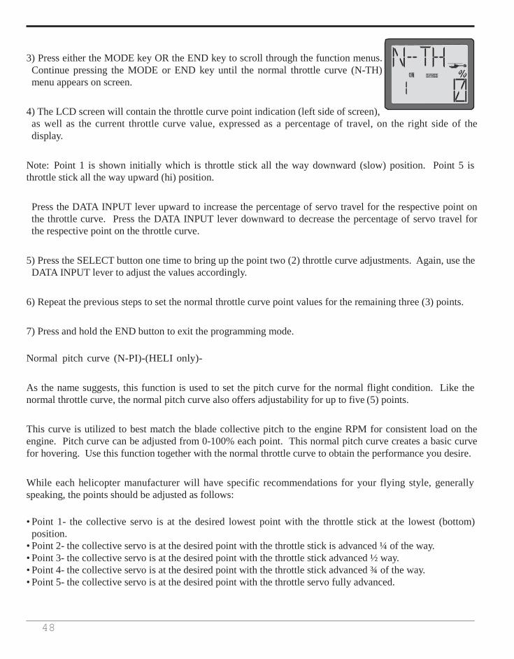
48
3) Press either the MODE key OR the END key to scroll through the function menus. Continue pressing the MODE or END key until the normal throttle curve (N-TH) menu appears on screen.
4) The LCD screen will contain the throttle curve point indication (left side of screen), as well as the current throttle curve value, expressed as a percentage of travel, on the right side of the display.
Note: Point 1 is shown initially which is throttle stick all the way downward (slow) position. Point 5 is throttle stick all the way upward (hi) position.
Press the DATA INPUT lever upward to increase the percentage of servo travel for the respective point on the throttle curve. Press the DATA INPUT lever downward to decrease the percentage of servo travel for the respective point on the throttle curve.
5) Press the SELECT button one time to bring up the point two (2) throttle curve adjustments. Again, use the DATA INPUT lever to adjust the values accordingly.
6) Repeat the previous steps to set the normal throttle curve point values for the remaining three (3) points.
7) Press and hold the END button to exit the programming mode.
Normal pitch curve (N-PI)-(HELI only)-
As the name suggests, this function is used to set the pitch curve for the normal flight condition. Like the normal throttle curve, the normal pitch curve also offers adjustability for up to five (5) points.
This curve is utilized to best match the blade collective pitch to the engine RPM for consistent load on the engine. Pitch curve can be adjusted from 0-100% each point. This normal pitch curve creates a basic curve for hovering. Use this function together with the normal throttle curve to obtain the performance you desire.
While each helicopter manufacturer will have specific recommendations for your flying style, generally speaking, the points should be adjusted as follows:
• Point 1- the collective servo is at the desired lowest point with the throttle stick at the lowest (bottom)
position. • Point 2- the collective servo is at the desired point with the throttle stick is advanced ¼ of the way. • Point 3- the collective servo is at the desired point with the throttle stick advanced ½ way. • Point 4- the collective servo is at the desired point with the throttle stick advanced ¾ of the way. • Point 5- the collective servo is at the desired point with the throttle servo fully advanced.
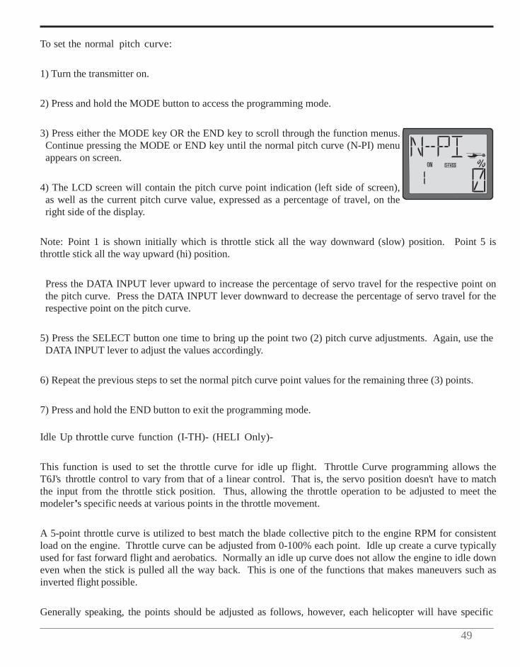
49
To set the normal pitch curve:
1) Turn the transmitter on.
2) Press and hold the MODE button to access the programming mode.
3) Press either the MODE key OR the END key to scroll through the function menus. Continue pressing the MODE or END key until the normal pitch curve (N-PI) menu appears on screen.
4) The LCD screen will contain the pitch curve point indication (left side of screen), as well as the current pitch curve value, expressed as a percentage of travel, on the right side of the display.
Note: Point 1 is shown initially which is throttle stick all the way downward (slow) position. Point 5 is throttle stick all the way upward (hi) position.
Press the DATA INPUT lever upward to increase the percentage of servo travel for the respective point on the pitch curve. Press the DATA INPUT lever downward to decrease the percentage of servo travel for the respective point on the pitch curve.
5) Press the SELECT button one time to bring up the point two (2) pitch curve adjustments. Again, use the DATA INPUT lever to adjust the values accordingly.
6) Repeat the previous steps to set the normal pitch curve point values for the remaining three (3) points.
7) Press and hold the END button to exit the programming mode.
Idle Up throttle curve function (I-TH)- (HELI Only)-
This function is used to set the throttle curve for idle up flight. Throttle Curve programming allows the T6J's throttle control to vary from that of a linear control. That is, the servo position doesn't have to match the input from the throttle stick position. Thus, allowing the throttle operation to be adjusted to meet the modeler's specific needs at various points in the throttle movement.
A 5-point throttle curve is utilized to best match the blade collective pitch to the engine RPM for consistent load on the engine. Throttle curve can be adjusted from 0-100% each point. Idle up create a curve typically used for fast forward flight and aerobatics. Normally an idle up curve does not allow the engine to idle down even when the stick is pulled all the way back. This is one of the functions that makes maneuvers such as inverted flight possible.
Generally speaking, the points should be adjusted as follows, however, each helicopter will have specific

50
recommendations for the style of flight desired:
• Point 1 is shown initially which is throttle stick all the way downward (slow) position. • Point 2 is the throttle stick approximately ¼ of the way advanced. • Point 3 is the throttle stick approximately ½ of the way advanced. • Point 4 is the throttle stick approximately 3/4 of the way advanced. • Point 5 is throttle stick all the way upward (hi) position.
To set the idle up throttle curve:
1) Turn the transmitter on.
2) Press and hold the MODE button to access the programming mode. An audible double beep will be heard and the default screen will change accordingly.
3) Press either the MODE key OR the END key to scroll through the function menus. Continue pressing the MODE or END key until the idle up throttle curve (I-TH) menu appears on screen.
4) Push the DATA INPUT lever upward for 0.5 seconds. This will cause the flashing INH display to change to a flashing ON display. Now the I-TH function is activated, although depending upon the position of the idle up switch, it may not be on.
5) Push the SELECT key. The LCD screen will contain the throttle curve point indication (left side of screen), as well as the current throttle curve value, expressed as a percentage of travel, on the right side of the display.
Note: Point 1 is shown initially which is throttle stick all the way downward (slow) position. Point 5 is throttle stick all the way upward (hi) position.
Press the DATA INPUT lever upward to increase the percentage of servo travel for the respective point on the throttle curve. Press the DATA INPUT lever downward to decrease the percentage of servo travel for the respective point on the throttle curve.
6) Press the SELECT button one time to bring up the point two (2) throttle curve adjustments. Again, use the DATA INPUT lever to adjust the values accordingly.
7) Repeat the previous steps to set the idle up throttle curve point values for the remaining three (3) points.
8) Press the DATA INPUT lever either upward or downward to select Switch A, B or C as the idle up activation switch.
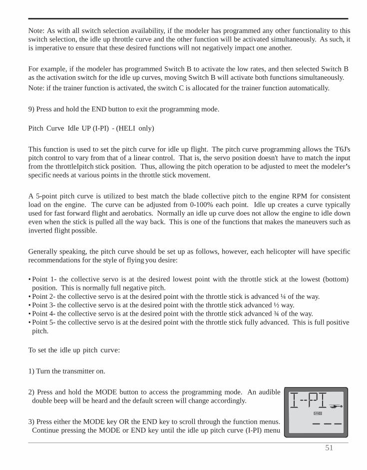
51
Note: As with all switch selection availability, if the modeler has programmed any other functionality to this switch selection, the idle up throttle curve and the other function will be activated simultaneously. As such, it is imperative to ensure that these desired functions will not negatively impact one another.
For example, if the modeler has programmed Switch B to activate the low rates, and then selected Switch B as the activation switch for the idle up curves, moving Switch B will activate both functions simultaneously. Note: if the trainer function is activated, the switch C is allocated for the trainer function automatically.
9) Press and hold the END button to exit the programming mode.
Pitch Curve Idle UP (I-PI) - (HELI only)
This function is used to set the pitch curve for idle up flight. The pitch curve programming allows the T6J's pitch control to vary from that of a linear control. That is, the servo position doesn't have to match the input from the throttleIpitch stick position. Thus, allowing the pitch operation to be adjusted to meet the modeler's specific needs at various points in the throttle stick movement.
A 5-point pitch curve is utilized to best match the blade collective pitch to the engine RPM for consistent load on the engine. The curve can be adjusted from 0-100% each point. Idle up creates a curve typically used for fast forward flight and aerobatics. Normally an idle up curve does not allow the engine to idle down even when the stick is pulled all the way back. This is one of the functions that makes the maneuvers such as inverted flight possible.
Generally speaking, the pitch curve should be set up as follows, however, each helicopter will have specific recommendations for the style of flying you desire:
• Point 1- the collective servo is at the desired lowest point with the throttle stick at the lowest (bottom)
position. This is normally full negative pitch. • Point 2- the collective servo is at the desired point with the throttle stick is advanced ¼ of the way. • Point 3- the collective servo is at the desired point with the throttle stick advanced ½ way. • Point 4- the collective servo is at the desired point with the throttle stick advanced ¾ of the way. • Point 5- the collective servo is at the desired point with the throttle stick fully advanced. This is full positive
pitch.
To set the idle up pitch curve:
1) Turn the transmitter on.
2) Press and hold the MODE button to access the programming mode. An audible double beep will be heard and the default screen will change accordingly.
3) Press either the MODE key OR the END key to scroll through the function menus. Continue pressing the MODE or END key until the idle up pitch curve (I-PI) menu
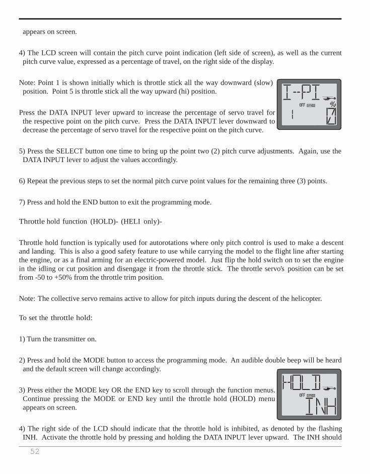
52
appears on screen.
4) The LCD screen will contain the pitch curve point indication (left side of screen), as well as the current pitch curve value, expressed as a percentage of travel, on the right side of the display.
Note: Point 1 is shown initially which is throttle stick all the way downward (slow) position. Point 5 is throttle stick all the way upward (hi) position.
Press the DATA INPUT lever upward to increase the percentage of servo travel for the respective point on the pitch curve. Press the DATA INPUT lever downward to decrease the percentage of servo travel for the respective point on the pitch curve.
5) Press the SELECT button one time to bring up the point two (2) pitch curve adjustments. Again, use the DATA INPUT lever to adjust the values accordingly.
6) Repeat the previous steps to set the normal pitch curve point values for the remaining three (3) points.
7) Press and hold the END button to exit the programming mode.
Throttle hold function (HOLD)- (HELI only)-
Throttle hold function is typically used for autorotations where only pitch control is used to make a descent and landing. This is also a good safety feature to use while carrying the model to the flight line after starting the engine, or as a final arming for an electric-powered model. Just flip the hold switch on to set the engine in the idling or cut position and disengage it from the throttle stick. The throttle servo's position can be set from -50 to +50% from the throttle trim position.
Note: The collective servo remains active to allow for pitch inputs during the descent of the helicopter.
To set the throttle hold:
1) Turn the transmitter on.
2) Press and hold the MODE button to access the programming mode. An audible double beep will be heard and the default screen will change accordingly.
3) Press either the MODE key OR the END key to scroll through the function menus. Continue pressing the MODE or END key until the throttle hold (HOLD) menu appears on screen.
4) The right side of the LCD should indicate that the throttle hold is inhibited, as denoted by the flashing INH. Activate the throttle hold by pressing and holding the DATA INPUT lever upward. The INH should
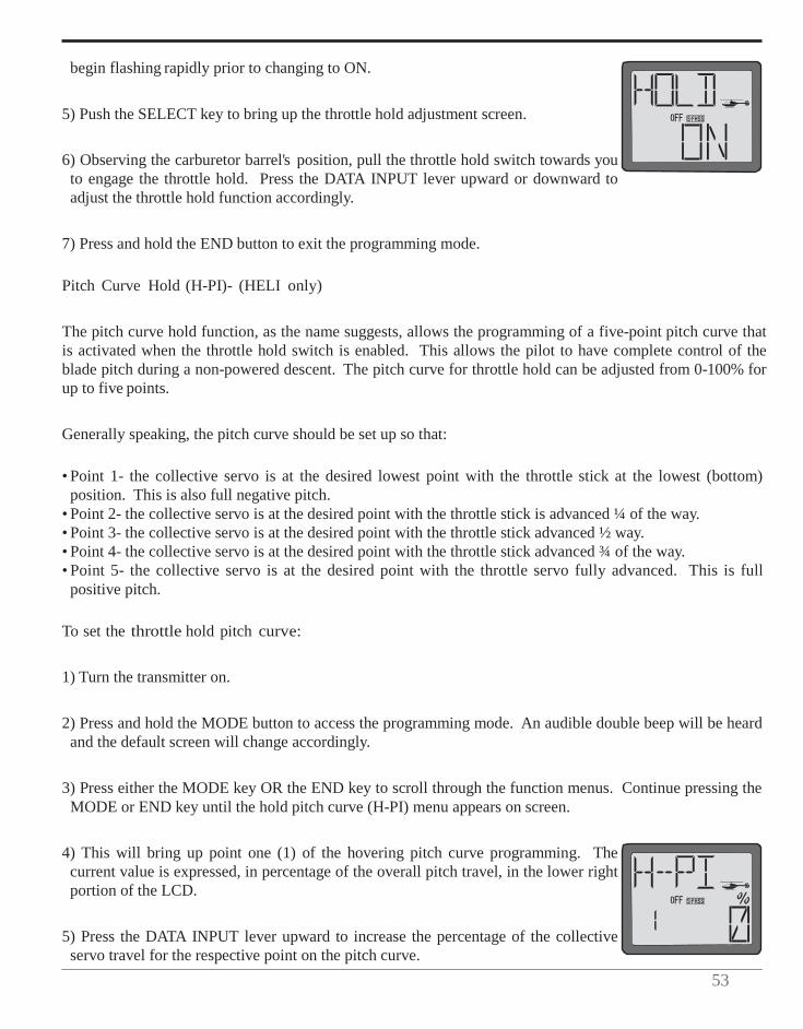
53
begin flashing rapidly prior to changing to ON.
5) Push the SELECT key to bring up the throttle hold adjustment screen.
6) Observing the carburetor barrel's position, pull the throttle hold switch towards you to engage the throttle hold. Press the DATA INPUT lever upward or downward to adjust the throttle hold function accordingly.
7) Press and hold the END button to exit the programming mode.
Pitch Curve Hold (H-PI)- (HELI only)
The pitch curve hold function, as the name suggests, allows the programming of a five-point pitch curve that is activated when the throttle hold switch is enabled. This allows the pilot to have complete control of the blade pitch during a non-powered descent. The pitch curve for throttle hold can be adjusted from 0-100% for up to five points.
Generally speaking, the pitch curve should be set up so that:
• Point 1- the collective servo is at the desired lowest point with the throttle stick at the lowest (bottom) position. This is also full negative pitch.
• Point 2- the collective servo is at the desired point with the throttle stick is advanced ¼ of the way. • Point 3- the collective servo is at the desired point with the throttle stick advanced ½ way. • Point 4- the collective servo is at the desired point with the throttle stick advanced ¾ of the way. • Point 5- the collective servo is at the desired point with the throttle servo fully advanced. This is full
positive pitch.
To set the throttle hold pitch curve:
1) Turn the transmitter on.
2) Press and hold the MODE button to access the programming mode. An audible double beep will be heard and the default screen will change accordingly.
3) Press either the MODE key OR the END key to scroll through the function menus. Continue pressing the MODE or END key until the hold pitch curve (H-PI) menu appears on screen.
4) This will bring up point one (1) of the hovering pitch curve programming. The current value is expressed, in percentage of the overall pitch travel, in the lower right portion of the LCD.
5) Press the DATA INPUT lever upward to increase the percentage of the collective servo travel for the respective point on the pitch curve.
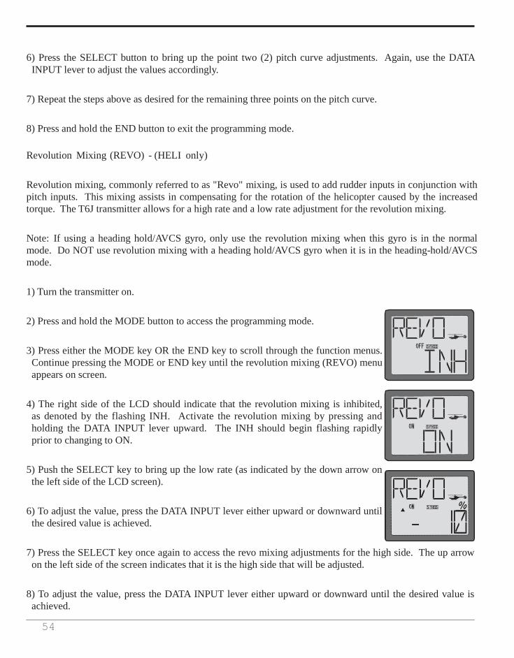
54
6) Press the SELECT button to bring up the point two (2) pitch curve adjustments. Again, use the DATA INPUT lever to adjust the values accordingly.
7) Repeat the steps above as desired for the remaining three points on the pitch curve.
8) Press and hold the END button to exit the programming mode.
Revolution Mixing (REVO) - (HELI only)
Revolution mixing, commonly referred to as "Revo" mixing, is used to add rudder inputs in conjunction with pitch inputs. This mixing assists in compensating for the rotation of the helicopter caused by the increased torque. The T6J transmitter allows for a high rate and a low rate adjustment for the revolution mixing.
Note: If using a heading hold/AVCS gyro, only use the revolution mixing when this gyro is in the normal mode. Do NOT use revolution mixing with a heading hold/AVCS gyro when it is in the heading-hold/AVCS mode.
1) Turn the transmitter on.
2) Press and hold the MODE button to access the programming mode.
3) Press either the MODE key OR the END key to scroll through the function menus. Continue pressing the MODE or END key until the revolution mixing (REVO) menu appears on screen.
4) The right side of the LCD should indicate that the revolution mixing is inhibited, as denoted by the flashing INH. Activate the revolution mixing by pressing and holding the DATA INPUT lever upward. The INH should begin flashing rapidly prior to changing to ON.
5) Push the SELECT key to bring up the low rate (as indicated by the down arrow on the left side of the LCD screen).
6) To adjust the value, press the DATA INPUT lever either upward or downward until the desired value is achieved.
7) Press the SELECT key once again to access the revo mixing adjustments for the high side. The up arrow on the left side of the screen indicates that it is the high side that will be adjusted.
8) To adjust the value, press the DATA INPUT lever either upward or downward until the desired value is achieved.
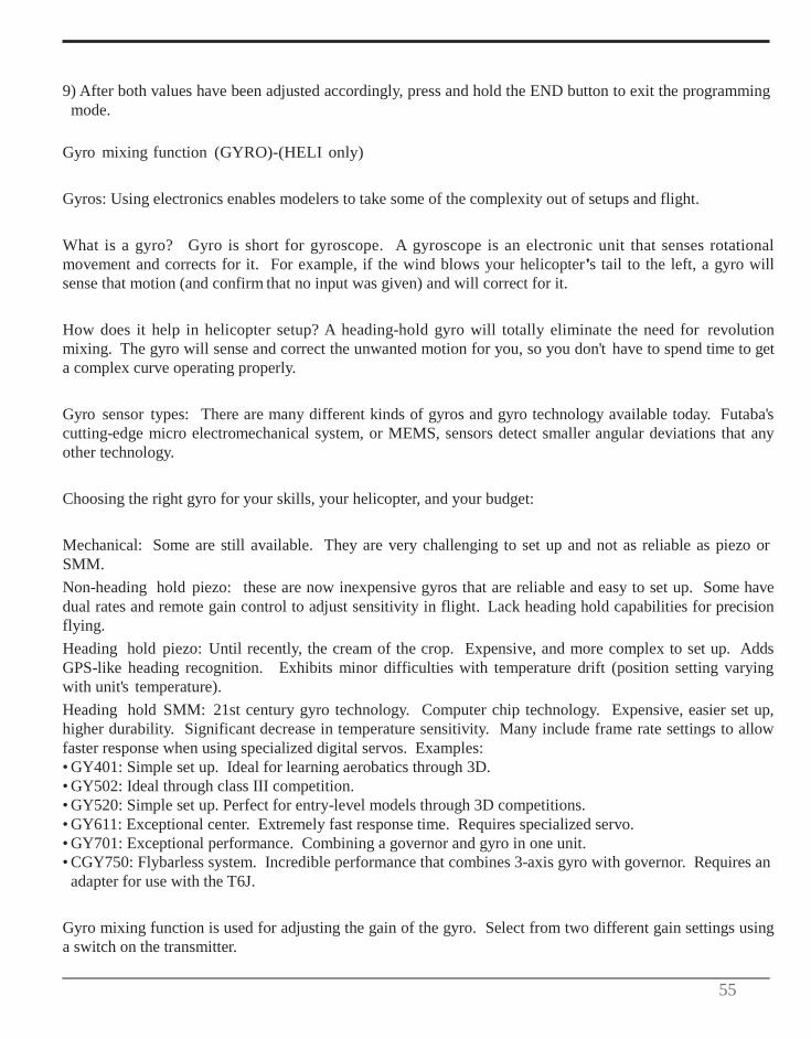
55
9) After both values have been adjusted accordingly, press and hold the END button to exit the programming mode.
Gyro mixing function (GYRO)-(HELI only)
Gyros: Using electronics enables modelers to take some of the complexity out of setups and flight.
What is a gyro? Gyro is short for gyroscope. A gyroscope is an electronic unit that senses rotational movement and corrects for it. For example, if the wind blows your helicopter's tail to the left, a gyro will sense that motion (and confirm that no input was given) and will correct for it.
How does it help in helicopter setup? A heading-hold gyro will totally eliminate the need for revolution mixing. The gyro will sense and correct the unwanted motion for you, so you don't have to spend time to get a complex curve operating properly.
Gyro sensor types: There are many different kinds of gyros and gyro technology available today. Futaba's cutting-edge micro electromechanical system, or MEMS, sensors detect smaller angular deviations that any other technology.
Choosing the right gyro for your skills, your helicopter, and your budget:
Mechanical: Some are still available. They are very challenging to set up and not as reliable as piezo or SMM. Non-heading hold piezo: these are now inexpensive gyros that are reliable and easy to set up. Some have dual rates and remote gain control to adjust sensitivity in flight. Lack heading hold capabilities for precision flying. Heading hold piezo: Until recently, the cream of the crop. Expensive, and more complex to set up. Adds GPS-like heading recognition. Exhibits minor difficulties with temperature drift (position setting varying with unit's temperature). Heading hold SMM: 21st century gyro technology. Computer chip technology. Expensive, easier set up, higher durability. Significant decrease in temperature sensitivity. Many include frame rate settings to allow faster response when using specialized digital servos. Examples: • GY401: Simple set up. Ideal for learning aerobatics through 3D. • GY502: Ideal through class III competition. • GY520: Simple set up. Perfect for entry-level models through 3D competitions. • GY611: Exceptional center. Extremely fast response time. Requires specialized servo. • GY701: Exceptional performance. Combining a governor and gyro in one unit. • CGY750: Flybarless system. Incredible performance that combines 3-axis gyro with governor. Requires an
adapter for use with the T6J.
Gyro mixing function is used for adjusting the gain of the gyro. Select from two different gain settings using a switch on the transmitter.
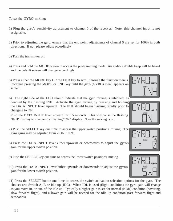
56
To set the GYRO mixing:
1) Plug the gyro's sensitivity adjustment to channel 5 of the receiver. Note: this channel input is not assignable.
2) Prior to adjusting the gyro, ensure that the end point adjustments of channel 5 are set for 100% in both directions. If not, please adjust accordingly.
3) Turn the transmitter on.
4) Press and hold the MODE button to access the programming mode. An audible double beep will be heard and the default screen will change accordingly.
5) Press either the MODE key OR the END key to scroll through the function menus. Continue pressing the MODE or END key until the gyro (GYRO) menu appears on screen.
6) The right side of the LCD should indicate that the gyro mixing is inhibited, as denoted by the flashing INH. Activate the gyro mixing by pressing and holding the DATA INPUT lever upward. The INH should begin flashing rapidly prior to changing to ON. Push the DATA INPUT lever upward for 0.5 seconds. This will cause the flashing "INH" display to change to a flashing "ON" display. Now the mixing is on.
7) Push the SELECT key one time to access the upper switch position's mixing. The gyro gains may be adjusted from -100-+100%.
8) Press the DATA INPUT lever either upwards or downwards to adjust the gyro's gain for the upper switch position.
9) Push the SELECT key one time to access the lower switch position's mixing.
10) Press the DATA INPUT lever either upwards or downwards to adjust the gyro's gain for the lower switch position.
11) Press the SELECT button one time to access the switch activation selection options for the gyro. The choices are: Switch A, B or Idle up (IDL). When IDL is used (flight condition) the gyro gain will change as you move in, or out, of the idle up. Typically a higher gain is set for normal (NOR) condition (hovering, slow forward flight); and a lower gain will be needed for the idle up condition (fast forward flight and aerobatics).
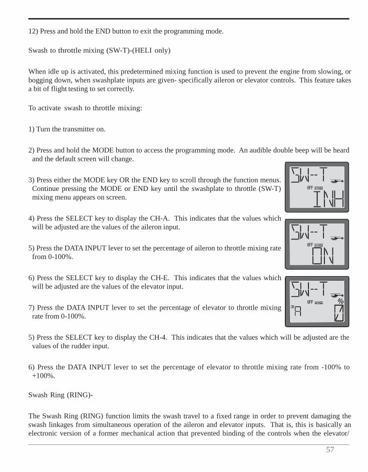
57
12) Press and hold the END button to exit the programming mode.
Swash to throttle mixing (SW-T)-(HELI only)
When idle up is activated, this predetermined mixing function is used to prevent the engine from slowing, or bogging down, when swashplate inputs are given- specifically aileron or elevator controls. This feature takes a bit of flight testing to set correctly.
To activate swash to throttle mixing:
1) Turn the transmitter on.
2) Press and hold the MODE button to access the programming mode. An audible double beep will be heard and the default screen will change.
3) Press either the MODE key OR the END key to scroll through the function menus. Continue pressing the MODE or END key until the swashplate to throttle (SW-T) mixing menu appears on screen.
4) Press the SELECT key to display the CH-A. This indicates that the values which will be adjusted are the values of the aileron input.
5) Press the DATA INPUT lever to set the percentage of aileron to throttle mixing rate from 0-100%.
6) Press the SELECT key to display the CH-E. This indicates that the values which will be adjusted are the values of the elevator input.
7) Press the DATA INPUT lever to set the percentage of elevator to throttle mixing rate from 0-100%.
5) Press the SELECT key to display the CH-4. This indicates that the values which will be adjusted are the values of the rudder input.
6) Press the DATA INPUT lever to set the percentage of elevator to throttle mixing rate from -100% to +100%.
Swash Ring (RING)-
The Swash Ring (RING) function limits the swash travel to a fixed range in order to prevent damaging the swash linkages from simultaneous operation of the aileron and elevator inputs. That is, this is basically an electronic version of a former mechanical action that prevented binding of the controls when the elevator/

58
aileron inputs are maximized.
This is very useful for 3D aerobatics. The Ring function is adjustable from 50-200%.
Futaba should create a gimbal stick diagram that depicts the swash ring and value effects. A circle could surround the gimbal. For example, show diagram with 50, 100 and 200% values input.
To set the swash ring:
1) Turn the transmitter on.
2) Press and hold the MODE button to access the programming mode. An audible double beep will be heard and the default screen will change accordingly.
3) Press either the MODE key OR the END key to scroll through the function menus. Each time one of the aforementioned keys is pressed the menu will change accordingly. Continue pressing the MODE or END key until the swash ring (RING) menu appears on screen.
4) The right side of the LCD should indicate that the swash ring is inhibited, as denoted by the flashing INH. Activate the swash ring by pressing and holding the DATA INPUT lever upward. The INH should begin flashing rapidly prior to changing to ON.
5) Press the SELECT key to call up the default value (50%).
6) To adjust the RING value, press the DATA INPUT lever upward until the desired value is achieved.
Observing your helicopter, ensure that the swash ring function has eliminated any undesired movement or binding when the extreme aileron/elevator inputs are given.
7) Press and hold the END button to exit the programming menu.
Swashplate type selection and Swash AFR (SWSH) - (HELI only)
The Swashplate type selection is utilized to select the swashplate type that matches the respective helicopter for which you are programming the transmitter. The T6J transmitter offers four Swashplate type selections to choose from: H-1, HE3, H-3 and HR3.
Prior to explaining the differences in the selections available to you, it is important to have a basic understanding of CCPM and "normal" swashplate types.
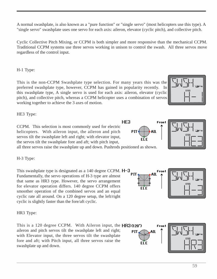
59
A normal swashplate, is also known as a "pure function" or "single servo" (most helicopters use this type). A "single servo" swashplate uses one servo for each axis: aileron, elevator (cyclic pitch), and collective pitch.
Cyclic Collective Pitch Mixing, or CCPM is both simpler and more responsive than the mechanical CCPM. Traditional CCPM systems use three servos working in unison to control the swash. All three servos move regardless of the control input.
H-1 Type:
This is the non-CCPM Swashplate type selection. For many years this was the preferred swashplate type, however, CCPM has gained in popularity recently. In this swashplate type, A single servo is used for each axis: aileron, elevator (cyclic pitch), and collective pitch, whereas a CCPM helicopter uses a combination of servos working together to achieve the 3 axes of motion.
HE3 Type:
CCPM. This selection is most commonly used for electric helicopters. With aileron input, the aileron and pitch servos tilt the swashplate left and right; with elevator input, the servos tilt the swashplate fore and aft; with pitch input, all three servos raise the swashplate up and down. Pushrods positioned as shown.
H-3 Type:
This swashplate type is designated as a 140 degree CCPM. Fundamentally, the servo operations of H-3 type are almost that same as HR3 type. However, the servo arrangement for elevator operation differs. 140 degree CCPM offers smoother operation of the combined servos and an equal cyclic rate all around. On a 120 degree setup, the left/right cyclic is slightly faster than the fore/aft cyclic.
HR3 Type:
This is a 120 degree CCPM. With Aileron input, the aileron and pitch servos tilt the swashplate left and right; with Elevator input, the three servos tilt the swashplate fore and aft; with Pitch input, all three servos raise the swashplate up and down.

60
To select the swashplate types:
1) Turn the transmitter on.
2) Press and hold the MODE button to access the programming mode.
3) Press either the MODE key OR the END key to scroll through the function menus. Continue pressing the MODE or END key until the swash (SWSH) menu appears on screen.
4) To select the swashplate type, press the DATA INPUT lever upward or downward for about two seconds. When you are changing swashplate types to H-1, HE3, H-3 or HR3 the display flashes slow, becomes rapid and then returns slow flashing with confirmation sound.
5) Press and hold the END button to exit the programming menu.
Swashplate AFR (Adjustable Function Rate) - (HELI only)
If any of the three CCPM Swashplate types (H3, HE3, or HR3) have been selected, the Swashplate AFR (adjustable function rate) settings will automatically be activated as well. It is possible to individually modify the values for the aileron, elevator and pitch servos to fine-tune the amount of travel and travel direction of the swashplate inputs.
Prior to adjusting the swashplate AFR, it is important to properly set the linkage and servo horns for the aileron, elevator and pitch servos according to the helicopter manufacturer's instructions. The correct geometry of these settings is imperative to a smooth, successful and correctly set-up CCPM helicopter.
Collective and pitch directions, as well as overall throw (all three servos working together) are controlled by the Swash AFR. To begin, set up it is recommended that the pitch curve be set in a straight line (0, 25, 50, 75 and 100), this will be set to the correct curves as shown in the Pitch Curve section on page ??. Initially the values displayed on the transmitter will be +50% for all three channels.
Check all three servos to move in the same direction by the throttle stick operation. At this point, it doesn't worry even if the swashplate works in the reverse direction for the stick operation. If one of these servos operate oppositely for other servos, you will need to change the travel direction of the servo in the servo reversing (REVR) menu. Please refer to page ?? for information on how to do so.
Next, check the cyclic directions (aileron and elevator) and the collective (pitch) direction. If the swashplate is working in the reverse direction for each stick operation, it will be necessary to change the respective swashplate AFR value to -50%.
With everything functioning in the proper direction it is time to adjust the overall throw for each function. Typically you will use a pitch gauge to assist in the adjustment of the pitch AFR to achieve the amount of
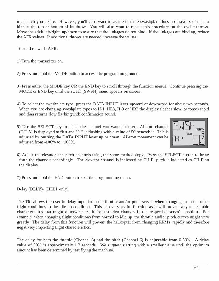
61
total pitch you desire. However, you'll also want to assure that the swashplate does not travel so far as to bind at the top or bottom of its throw. You will also want to repeat this procedure for the cyclic throws. Move the stick left/right, up/down to assure that the linkages do not bind. If the linkages are binding, reduce the AFR values. If additional throws are needed, increase the values.
To set the swash AFR:
1) Turn the transmitter on.
2) Press and hold the MODE button to access the programming mode.
3) Press either the MODE key OR the END key to scroll through the function menus. Continue pressing the MODE or END key until the swash (SWSH) menu appears on screen.
4) To select the swashplate type, press the DATA INPUT lever upward or downward for about two seconds. When you are changing swashplate types to H-1, HE3, H-3 or HR3 the display flashes slow, becomes rapid and then returns slow flashing with confirmation sound.
5) Use the SELECT key to select the channel you wanted to set. Aileron channel (CH-A) is displayed at first and "%" is flashing with a value of 50 beneath it. This is adjusted by pushing the DATA INPUT lever up or down. Aileron movement can be adjusted from -100% to +100%.
6) Adjust the elevator and pitch channels using the same methodology. Press the SELECT button to bring forth the channels accordingly. The elevator channel is indicated by CH-E; pitch is indicated as CH-P on the display.
7) Press and hold the END button to exit the programming menu.
Delay (DELY)- (HELI only)
The T6J allows the user to delay input from the throttle and/or pitch servos when changing from the other flight conditions to the idle-up condition. This is a very useful function as it will prevent any undesirable characteristics that might otherwise result from sudden changes in the respective servo's position. For example, when changing flight conditions from normal to idle up, the throttle andIor pitch curves might vary greatly. The delay from this function will prevent the helicopter from changing RPM's rapidly and therefore negatively impacting flight characteristics.
The delay for both the throttle (Channel 3) and the pitch (Channel 6) is adjustable from 0-50%. A delay value of 50% is approximately 1.2 seconds. We suggest starting with a smaller value until the optimum amount has been determined by test flying the machine.
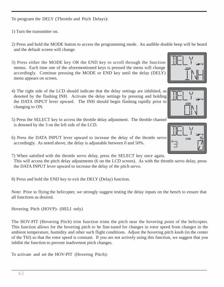
62
To program the DELY (Throttle and Pitch Delays):
1) Turn the transmitter on.
2) Press and hold the MODE button to access the programming mode. An audible double beep will be heard and the default screen will change.
3) Press either the MODE key OR the END key to scroll through the function menus. Each time one of the aforementioned keys is pressed the menu will change accordingly. Continue pressing the MODE or END key until the delay (DELY) menu appears on screen.
4) The right side of the LCD should indicate that the delay settings are inhibited, as denoted by the flashing INH. Activate the delay settings by pressing and holding the DATA INPUT lever upward. The INH should begin flashing rapidly prior to changing to ON.
5) Press the SELECT key to access the throttle delay adjustment. The throttle channel is denoted by the 3 on the left side of the LCD.
6) Press the DATA INPUT lever upward to increase the delay of the throttle servo accordingly. As noted above, the delay is adjustable between 0 and 50%.
7) When satisfied with the throttle servo delay, press the SELECT key once again. This will access the pitch delay adjustments (6 on the LCD screen). As with the throttle servo delay, press the DATA INPUT lever upward to increase the delay of the pitch servo.
8) Press and hold the END key to exit the DELY (Delay) function.
Note: Prior to flying the helicopter, we strongly suggest testing the delay inputs on the bench to ensure that all functions as desired.
Hovering Pitch (HOVP)- (HELI only)
The HOV-PIT (Hovering Pitch) trim function trims the pitch near the hovering point of the helicopter. This function allows for the hovering pitch to be fine-tuned for changes in rotor speed from changes in the ambient temperature, humidity and other such flight conditions. Adjust the hovering pitch knob (in the center of the T6J) so that the rotor speed is constant. If you are not actively using this function, we suggest that you inhibit the function to prevent inadvertent pitch changes.
To activate and set the HOV-PIT (Hovering Pitch):
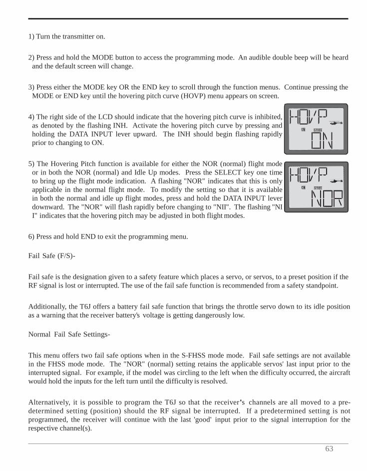
63
1) Turn the transmitter on.
2) Press and hold the MODE button to access the programming mode. An audible double beep will be heard and the default screen will change.
3) Press either the MODE key OR the END key to scroll through the function menus. Continue pressing the MODE or END key until the hovering pitch curve (HOVP) menu appears on screen.
4) The right side of the LCD should indicate that the hovering pitch curve is inhibited, as denoted by the flashing INH. Activate the hovering pitch curve by pressing and holding the DATA INPUT lever upward. The INH should begin flashing rapidly prior to changing to ON.
5) The Hovering Pitch function is available for either the NOR (normal) flight mode or in both the NOR (normal) and Idle Up modes. Press the SELECT key one time to bring up the flight mode indication. A flashing "NOR" indicates that this is only applicable in the normal flight mode. To modify the setting so that it is available in both the normal and idle up flight modes, press and hold the DATA INPUT lever downward. The "NOR" will flash rapidly before changing to "NII". The flashing "NI I" indicates that the hovering pitch may be adjusted in both flight modes.
6) Press and hold END to exit the programming menu.
Fail Safe (F/S)-
Fail safe is the designation given to a safety feature which places a servo, or servos, to a preset position if the RF signal is lost or interrupted. The use of the fail safe function is recommended from a safety standpoint.
Additionally, the T6J offers a battery fail safe function that brings the throttle servo down to its idle position as a warning that the receiver battery's voltage is getting dangerously low.
Normal Fail Safe Settings-
This menu offers two fail safe options when in the S-FHSS mode mode. Fail safe settings are not available in the FHSS mode mode. The "NOR" (normal) setting retains the applicable servos' last input prior to the interrupted signal. For example, if the model was circling to the left when the difficulty occurred, the aircraft would hold the inputs for the left turn until the difficulty is resolved.
Alternatively, it is possible to program the T6J so that the receiver's channels are all moved to a pre- determined setting (position) should the RF signal be interrupted. If a predetermined setting is not programmed, the receiver will continue with the last 'good' input prior to the signal interruption for the respective channel(s).

64
To set the Fail Safe Function:
1) Turn the transmitter on.
2) Press and hold the MODE button to access the programming mode.
3) Press either the MODE key OR the END key to scroll through the function menus. Continue pressing the MODE or END key until the fail safe (F/S) menu appears on screen.
4) Place the switches, sticks and/or rotary knob in the desired fail safe positions. Press and hold the DATA INPUT lever downward to retain these current positions as the Fail Safe settings. Press the SELECT button to scroll through the channels individually to view the saved fail safe positions.
Note: Should you wish to adjust each channel's fail safe position separately, it is possible to do so. Simply use the SELECT button to scroll to the desired channel and then hold the DATA INPUT lever downward as in step 4, above.
We strongly suggest verification of the fail safe function prior to flight of the model. This will ensure that all channels will function as so desired. To verify the F/S function has been correctly set, turn off the transmitter, the servos should move to the positions as determined in step two (4) above.
If you wish to eliminate a preset position for any of the channels, use the SELECT button to choose the desired channel. Next, press and hold the DATA INPUT lever upward. The previously saved position value will be replaced with "NOR" or normal setting.
5) Press and hold the END button to exit the programming menu.
TRNR Trainer function-
The T6J offers a programmable trainer function. There are three trainer modes available for Channels 1-4. If applicable, Channels 5 and 6, offer two trainer modes. The trainer function makes it possible for the instructor to choose which functions or channels are to be used for the student's flight instruction. By retaining certain controls, this will make training of the student easier and the student is more likely to progress at a more rapid rate. The instructor can add controls and complexity to the student lessons at any time by assigning additional channels as so desired.
When the instructor activates the trainer switch, the student will gain control of all assigned channels and functionality of the aircraft. When released, the instructor regains all control of the aircraft.
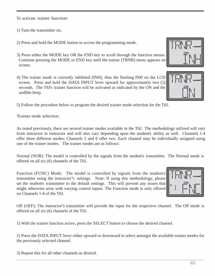
65
To activate trainer function:
1) Turn the transmitter on.
2) Press and hold the MODE button to access the programming mode.
3) Press either the MODE key OR the END key to scroll through the function menus. Continue pressing the MODE or END key until the trainer (TRNR) menu appears on screen.
4) The trainer mode is currently inhibited (INH), thus the flashing INH on the LCD screen. Press and hold the DATA INPUT lever upward for approximately two (2) seconds. The T6J's trainer function will be activated as indicated by the ON and the audible beep.
5) Follow the procedure below to program the desired trainer mode selection for the T6J.
Trainer mode selection:
As noted previously, there are several trainer modes available in the T6J. The methodology utilized will vary from instructor to instructor and will also vary depending upon the student's ability as well. Channels 1-4 offer three different modes; Channels 5 and 6 offer two. Each channel may be individually assigned using one of the trainer modes. The trainer modes are as follows:
Normal (NOR): The model is controlled by the signals from the student's transmitter. The Normal mode is offered on all six (6) channels of the T6J.
Function (FUNC) Mode: The model is controlled by signals from the student's transmitter using the instructor's settings. Note: If using this methodology, please set the student's transmitter to the default settings. This will prevent any issues that might otherwise arise with varying control inputs. The Function mode is only offered on Channels 1-4 of the T6J.
Off (OFF): The instructor's transmitter will provide the input for the respective channel. The Off mode is offered on all six (6) channels of the T6J.
1) With the trainer function active, press the SELECT button to choose the desired channel.
2) Press the DATA INPUT lever either upward or downward to select amongst the available trainer modes for the previously selected channel.
3) Repeat this for all other channels as desired.
66
4) To exit the trainer menu, press and hold the END button. This will bring forth the home page.
5) Upon completion of the trainer mode selection, please ensure that all functions as anticipated. To do so, connect the student's transmitter and the instructor's transmitter accordingly, and activate the trainer function on the instructor's transmitter by depressing Switch C on the top of the T6J transmitter.
Connecting the Instructor's and the Student's Transmitters for Training:
CAUTION: Some transmitters 'map' channels in a different order than that of the 6J. If the student transmitter is something other than another 6J, prior to flight it is strongly suggested that you verify that all channels (control surfaces, etc.) are working correctly in both transmitters.
Trainer switch-
To utilize the trainer function, the appropriate trainer cord (available separately) and a second Futaba transmitter (usually provided by your flight instructor or RIC club) will be required. When two radios are connected with the trainer cord, they are both capable of operating the model, but it's usually best for the instructor to hold the radio that has been setup for the plane to be flown (as it is already programmed to fly the model). When the instructor holds the trainer switch on his radio, the student will have control. When the instructor wishes to regain control he simply releases the switch.
Trainer cord-
Instructor's TX Student's TX Trainer cord
6J 10C, 9C, 7C, 6EX, 4EX Micro type for 12FG 14MZ, 12Z, 12FG, 8FG, 6J
Micro type 14MZ, 12Z, 12FG, 8FG, 10C, 9C, 7C, 6EX, 4EX
6J
If connecting the T6J-2.4GHz to another T6J-2.4GHz with the small, square "micro" trainer jack, use the "micro to micro" (MM-TC) trainer cord (FUTM4415). Never connect the T6J-2.4GHz trainer system with Futaba radios that have the large round "DIN" connector type as it will cause your T6J-2.4GHz to malfunction. The T6J-2.4GHz transmitter may be connected to another T6J-2.4GHz, or any T4EX, T6EXA, T9C, T12Z, T14MZ, FX-40 series transmitter.
To use the trainer function:
1) It is best for the instructor to use the transmitter that is already set up for the model to be flown.
2) If the student's radio has PCMIPPM capability, set it to PPM.

67
3) If the student's radio has a plug-in RF module, remove the module.
4) If the student's transmitter is a 72MHz, collapse the antenna accordingly.
5) With both transmitters off, connect the trainer cord to both radios. (On the T6J-2.4GHz the trainer jack is located in the center of the rear of the case). Do not force the plug into the transmitter and note that the plug is "keyed" so it can go in only one way.
6) Turn on the instructor's transmitter. DO NOT turn on the student's transmitter. It will automatically "power up", but will not transmit a signal. Set the reversing and trims of the student's radio to match that of the instructor's. If both the instructor and the student use T6J-2.4GHz, the FIS function's set-up must be the same in both transmitters.
7) Turn on the receiver switch in the model. Depress the trainer switch on the instructor's radio. Use the student's radio to operate the controls (ailerons, elevator, rudder, etc.) and observe how they respond. Make any adjustments necessary to the student's transmitter to get the controls to respond correctly.
8) Check to see that the trims are in "sync" by toggling the trainer switch back and forth a few times. The controls on the model should remain stationary. If the controls do not remain stationary, this indicates that the trim settings on the student's radio do not match those on the instructor's radio. Adjust the student's trims as necessary.
Note: When the instructor initially depresses the trainer switch on his transmitter, there will be approximately a one (1) second delay before the student takes control. In most situations this momentary delay will go unnoticed.
TIMER
The T6J offers three timers: count up, count down and model. The count up (stopwatch) and count down timer are programmable and feature an audible alarm when the programmed time limits have been reached. The model timer, as the name suggests, is used to track time of the model.
Countdown times sound one short beep each second during the last 10 (ten) seconds of the countdown function and one long tone when at the programmed time. The timer will then display a minus (-) sign and continue tracking the time.
The count up timer will also beep one short beep each second for the last ten (10) seconds and then one long tone at the programmed time. Additionally, the count up timer will continue counting upwards, there will not be a minus (-) sign, however.
As noted above, the model timer is used to track the time of the model. This is a count up timer and starts when the respective model memory is selected and the T6J is powered up.

68
The countdown and count up timers may be assigned to switches A, B or D (either up or down position), always ON or activated by the throttle stick movement. The countdown and count up timers may be programmed to track up to 99 minutes and 59 seconds. The model timer tracks the model's time up to 99 hours and 59 minutes.
It is also important to note that the timers are stored independently with each model, meaning that when switching between models, the timer associated with the model is brought up automatically.
The Model (MDL) timer is the default setting for the timer function. It is automatically activated and there is no programming necessary. The countdown timer is indicated by the "d" on the left portion of the LCD. A count up timer is indicated by a "U". To return to the transmitter voltage, press the SELECT button once again.
To reset the Model Timer:
As noted above, the model timer is not programmable. If a countdown or count up timer has not been activated in the T6J, the model timer will begin counting up automatically when the transmitter is turned on.
1) To view the time from the default screen, press the SELECT button. The transmitter voltage will be replaced by the MDL timer on the LCD.
2) To reset the model timer, press and hold the DATA INPUT lever either upward or downward. The LCD timer will return to 0:00. The T6J will also confirm the reset with an audible double beep.
To Set the Countdown or Count Up Timer:
1) Turn the transmitter on.
2) Press and hold the MODE button to access the programming mode.
3) Press either the MODE key OR the END key to scroll through the function menus. Continue pressing the MODE or END key until the timer (TIMR) menu appears on screen.
4) The MDL (Model) timer will be flashing on the screen. Press the DATA INPUT lever either upward or downward to select between the UP (count up) or DWN (count-down) timers.
5) Press the SELECT button to confirm the desired timer function. This will also move to the timer setting screen.
69
6) Use the DATA INPUT lever to adjust the timer's minute indications accordingly. Pushing upward will
increase the minute selection, to a maximum of 99 minutes. Pressing downward will decrease the minutes to a minimum of 00.
7) When satisfied, press the SELECT key again to move to the seconds adjustments. The seconds are adjustable from a minimum of 00 to a maximum of 59.
8) Pressing SELECT once again will move to the timer starting method screen. Press the DATA INPUT lever upward or downward to select accordingly. The options are:
• + SWA- Switch A(ON in the down position) • - SWA- Switch A(ON in the up position) • + SWB- Switch B(ON in the down position) • - SWB- Switch B(ON in the up position) • + SWD- Switch D(ON in the down position) • - SWD- Switch D(ON in the up position) • THR- Throttle stick movement activation, activates at approximately1/3 throttle • ON- The timer is always activated
Note: To stop the timer when activated, simply move the respective switch or stick to the opposite position. For example, if +SWA is selected and the timer is activated, simply move Switch A to the down position and the timer will stop accordingly. To reactivate the timer, move it to the up position once again.
To reset the timer, press and hold the DATA INPUT lever momentarily when the timer is displayed on the LCD.
9) Press and hold the END button to exit the programming menu.
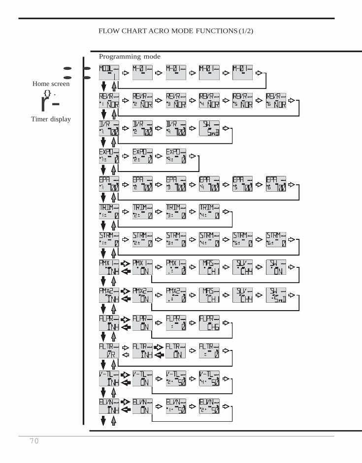
70
::
FLOW CHART ACRO MODE FUNCTIONS (1/2)
Home screen
r{}-. Timer display
Programming mode

71
FLOW CHART ACRO MODE FUNCTIONS (2/2)
MODE key
END key
SELECT key
DATA +/- lever
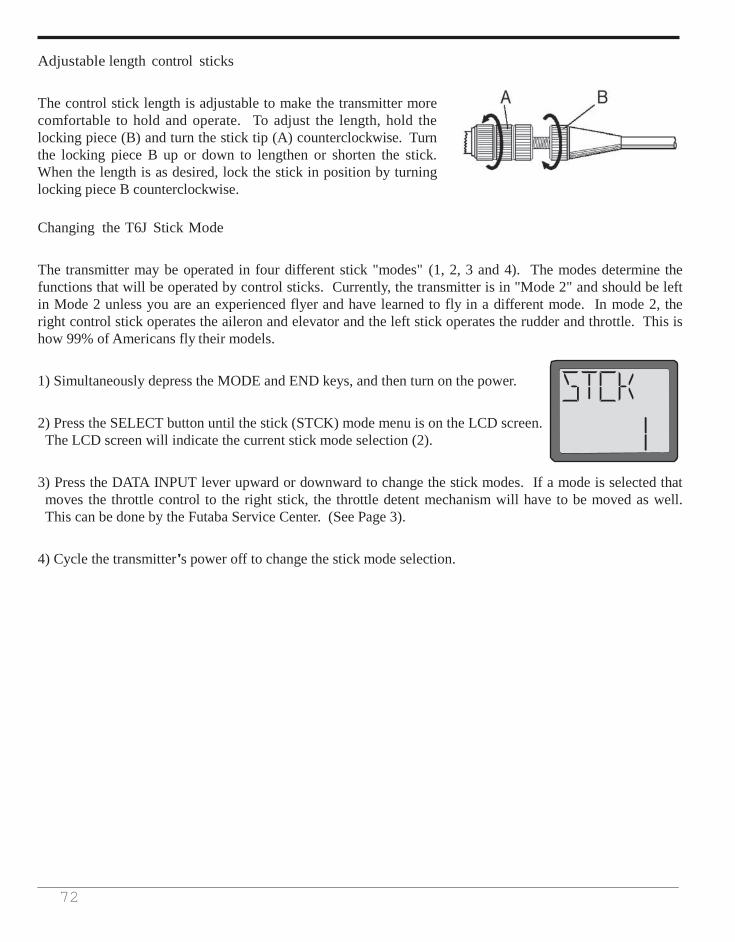
72
Adjustable length control sticks
The control stick length is adjustable to make the transmitter more comfortable to hold and operate. To adjust the length, hold the locking piece (B) and turn the stick tip (A) counterclockwise. Turn the locking piece B up or down to lengthen or shorten the stick. When the length is as desired, lock the stick in position by turning locking piece B counterclockwise.
Changing the T6J Stick Mode
The transmitter may be operated in four different stick "modes" (1, 2, 3 and 4). The modes determine the functions that will be operated by control sticks. Currently, the transmitter is in "Mode 2" and should be left in Mode 2 unless you are an experienced flyer and have learned to fly in a different mode. In mode 2, the right control stick operates the aileron and elevator and the left stick operates the rudder and throttle. This is how 99% of Americans fly their models.
1) Simultaneously depress the MODE and END keys, and then turn on the power.
2) Press the SELECT button until the stick (STCK) mode menu is on the LCD screen. The LCD screen will indicate the current stick mode selection (2).
3) Press the DATA INPUT lever upward or downward to change the stick modes. If a mode is selected that moves the throttle control to the right stick, the throttle detent mechanism will have to be moved as well. This can be done by the Futaba Service Center. (See Page 3).
4) Cycle the transmitter's power off to change the stick mode selection.
73
FLYING SAFETY GUIDELINES
Find a suitable flying site (for USA)
If you are a beginning modeler and not yet a member of an RIC club, joining a club and flying at a site specifically intended for R/C model aircraft is highly recommended. In addition to joining a club, we strongly recommend joining the AMA (Academy of Model Aeronautics). Among other benefits, the AMA provides insurance to its members who fly at sanctioned sites and events. Additionally, training programs and instructors are available at AMA club sites to help you get started the right way. Contact the AMA at the address or toll-free phone number below:
Academy of Model Aeronautics
5161 East Memorial Drive Muncie, IN 47302-9252 Tel: 1-(800)-435-9262 Fax: 1-(765)-741-0057
Or via the internet at: http://www.modelaircraft.org
Charge the batteries
Second to the pilot's flight skills, one of the most important factors that can determine a model's longevity is the state-of-charge of the batteries- especially the on-board receiver pack. Inadequate charging and failing to monitor a battery's voltage may lead to low battery power, causing loss of control and a crash. To avoid this, always charge the batteries the night before you go flying. If ever uncertain how much "charge" is left in a battery, it is wiser to err on the side of caution, rather than trying to get in one last flight! Due to the number of factors that determine receiver battery power consumption (such as the number and type of servos in your model, the type of flying you do, how much resistance is built into the controls, the size of the model, etc.), it is not possible to recommend how many flights one can get on a charge. The best way to monitor battery power and calculate how much flight time you have left is to use a volt meter to check the batteries after each flight. This can be done through the battery charging plug coming from the switch. There are many small, hand-held volt meters available specially intended for R/C use. The Hobbico® Digital Voltmeter MKIII™ is one such unit. An on-board volt meter mounted directly on the model (HCAP0330) can also be used.
74
Flight Preparation
Flight preparation is to be done at the flying field.
If you are an inexperienced pilot, be certain your flight instructor performs these following checks with you.
Check the controls
1) Get the frequency clip from the frequency control board at your flying site if the site has a clip for 2.4GHz.
2) Mount the wing to the fuselage. Turn on the transmitter, then the receiver (remember to do this in reverse order when turning off the system). Be certain the correct memory matching the model you will be flying is the one on the LCD screen.
3) Operate and observe the controls. Look for inadvertent movement and listen for abnormal servo sounds. If problems are noted, correct them before flying. Look for binding pushrods or servo arms or pushrods that interfere with each other.
4) One at a time, operate each control on the airplane using the sticks on the transmitter to make certain each control is responding correctly. This must be done before every flight. (There are several types of malfunctions that can be discovered by performing this elementary task, thus saving your model!)
Do Not fly in the rain!
Moisture may enter the transmitter through the antenna or stick openings and cause erratic operation or loss of control. If you must fly in wet weather during a contest, be sure to cover the transmitter with a plastic bag or other waterproof cover.
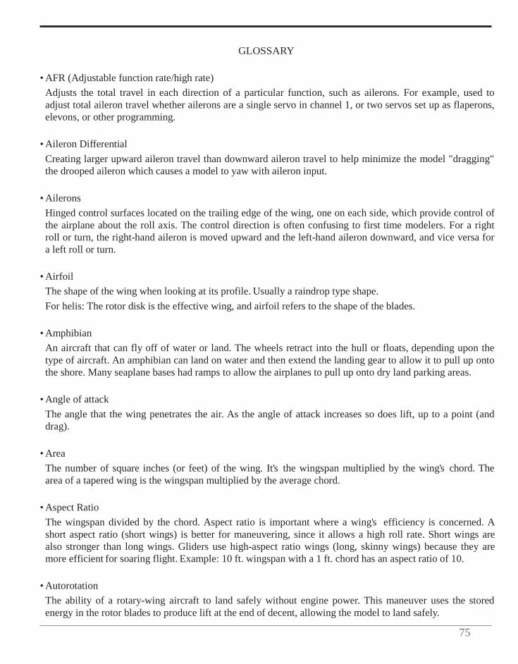
75
GLOSSARY
• AFR (Adjustable function rate/high rate) Adjusts the total travel in each direction of a particular function, such as ailerons. For example, used to adjust total aileron travel whether ailerons are a single servo in channel 1, or two servos set up as flaperons, elevons, or other programming.
• Aileron Differential
Creating larger upward aileron travel than downward aileron travel to help minimize the model "dragging" the drooped aileron which causes a model to yaw with aileron input.
• Ailerons
Hinged control surfaces located on the trailing edge of the wing, one on each side, which provide control of the airplane about the roll axis. The control direction is often confusing to first time modelers. For a right roll or turn, the right-hand aileron is moved upward and the left-hand aileron downward, and vice versa for a left roll or turn.
• Airfoil
The shape of the wing when looking at its profile. Usually a raindrop type shape. For helis: The rotor disk is the effective wing, and airfoil refers to the shape of the blades.
• Amphibian An aircraft that can fly off of water or land. The wheels retract into the hull or floats, depending upon the type of aircraft. An amphibian can land on water and then extend the landing gear to allow it to pull up onto the shore. Many seaplane bases had ramps to allow the airplanes to pull up onto dry land parking areas.
• Angle of attack
The angle that the wing penetrates the air. As the angle of attack increases so does lift, up to a point (and drag).
• Area
The number of square inches (or feet) of the wing. It's the wingspan multiplied by the wing's chord. The area of a tapered wing is the wingspan multiplied by the average chord.
• Aspect Ratio
The wingspan divided by the chord. Aspect ratio is important where a wing's efficiency is concerned. A short aspect ratio (short wings) is better for maneuvering, since it allows a high roll rate. Short wings are also stronger than long wings. Gliders use high-aspect ratio wings (long, skinny wings) because they are more efficient for soaring flight. Example: 10 ft. wingspan with a 1 ft. chord has an aspect ratio of 10.
• Autorotation
The ability of a rotary-wing aircraft to land safely without engine power. This maneuver uses the stored energy in the rotor blades to produce lift at the end of decent, allowing the model to land safely.

76
• Axis
The line around which a body rotates.
• BEC (Battery Eliminator Circuitry) Allows receiver to draw power from a main battery pack, eliminating the need for (and weight of) a receiver battery.
• Ball Bearing Servo's output shaft is supported with bearings for increased performance and accuracy.
• Ball Link Connection using a ball, and a link which rotates on the ball. Used to connect the servo to a control surface or lever.
• Backlash
Term describing the amount of play between gears, or gear mesh. If too loose, the gear can slip, or strip the teeth. Too tight, and excessive wear is caused.
• Base Load Antenna
A rigid, short antenna mounted to the model. Used to replace the longer receiver antenna.
• Battery Fail safe function Determines how to regain throttle control after a receiver low battery warning.
• Bell and Hiller Control system used in helicopters. Changes pitch of blades in relation to their position via a swashplate. A flybar with paddles is used to gain responsiveness. The two systems are linked with Control Levers.
• Binding What occurs when the friction at a joint is stronger than the linkage.
• Boring holes in the sky Having fun flying an RIC airplane, without any pre-determined flight pattern.
• "Buddy" or Trainer Box Two similar transmitters that are wired together with a "trainer cord." This is most useful when learning to fly-it's the same as having dual controls. The instructor can take control by using the "trainer switch" on his transmitter.
• CA
Abbreviation for cyanoacrylate. An instant type glue that is available in various viscosities (Thin, Medium, Thick, and Gel). These glues are ideal for the assembly of wood airplanes and other materials. NOTE: Most
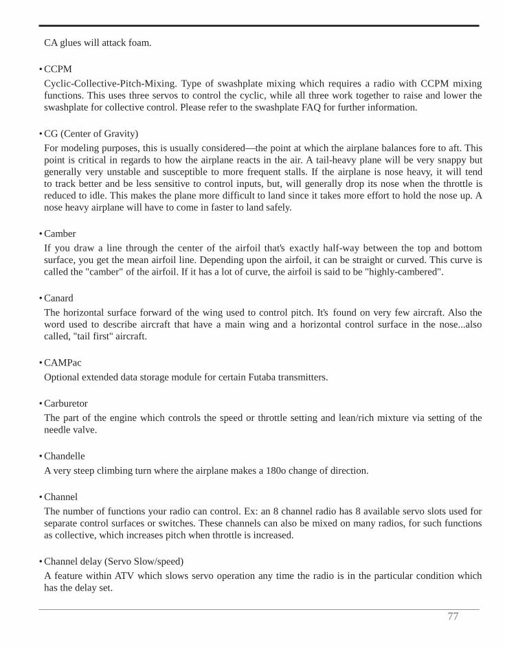
77
CA glues will attack foam.
• CCPM Cyclic-Collective-Pitch-Mixing. Type of swashplate mixing which requires a radio with CCPM mixing functions. This uses three servos to control the cyclic, while all three work together to raise and lower the swashplate for collective control. Please refer to the swashplate FAQ for further information.
• CG (Center of Gravity)
For modeling purposes, this is usually considered—the point at which the airplane balances fore to aft. This point is critical in regards to how the airplane reacts in the air. A tail-heavy plane will be very snappy but generally very unstable and susceptible to more frequent stalls. If the airplane is nose heavy, it will tend to track better and be less sensitive to control inputs, but, will generally drop its nose when the throttle is reduced to idle. This makes the plane more difficult to land since it takes more effort to hold the nose up. A nose heavy airplane will have to come in faster to land safely.
• Camber
If you draw a line through the center of the airfoil that's exactly half-way between the top and bottom surface, you get the mean airfoil line. Depending upon the airfoil, it can be straight or curved. This curve is called the "camber" of the airfoil. If it has a lot of curve, the airfoil is said to be "highly-cambered".
• Canard
The horizontal surface forward of the wing used to control pitch. It's found on very few aircraft. Also the word used to describe aircraft that have a main wing and a horizontal control surface in the nose...also called, "tail first" aircraft.
• CAMPac
Optional extended data storage module for certain Futaba transmitters.
• Carburetor The part of the engine which controls the speed or throttle setting and lean/rich mixture via setting of the needle valve.
• Chandelle
A very steep climbing turn where the airplane makes a 180o change of direction.
• Channel The number of functions your radio can control. Ex: an 8 channel radio has 8 available servo slots used for separate control surfaces or switches. These channels can also be mixed on many radios, for such functions as collective, which increases pitch when throttle is increased.
• Channel delay (Servo Slow/speed)
A feature within ATV which slows servo operation any time the radio is in the particular condition which has the delay set.

78
• Charge Jack
The plug receptacle of the switch harness into which the charger is plugged to charge the airborne battery. An expanded scale voltmeter (ESV) can also be plugged into it to check battery voltage between flights. It is advisable to mount the charge jack in an accessible area of the fuselage so an ESV can be used without removing the wing.
• Charger
Device used to recharge batteries and usually supplied with the radio if NiCd batteries are included.
• Chord The "depth" of the wing, its distance from leading edge to trailing edge. One of the components used to determine wing area. May vary from root to tip.
• Collective pitch (Air only)
Used to regulate variable pitch props to slow model and keep engine running in vertical dives and provide maximum torque in model's vertical climbs. Idle trim is used for how high the idle is when in reverse pitch (diving) and the pitch trim finely adjusts the amount of pitch at full throttle to avoid over-propping the engine.
• Control Surface
Any one of the various moveable portions of the wings, tail surfaces, or canard.
• Conventional Gear The landing gear arrangement where the airplane has a main gear and a tailwheel.
• Coreless motor In a conventional servo, the motor has a steel core armature wrapped in wire that spins inside the magnets. In a coreless design, the armature uses a thin wire mesh that forms a cup that spins around the outside of the magnet eliminating the heavy steel core. A coreless motor does not have magnets as standard servo motors do, so they have a smoother, more constant, and stronger action. Regular servo motors have either 3 or 5 magnets (poles) which when the armature is between these, the servo motor is at its weakest.
• Cowl
The large molded fairing around an engine. It serves two purposes when done right: It helps the airflow go smoothly around the front of the airplane, and also provides a proper path for cooling air around the engine.
• Cyclic
Term used for the horizontal controls used to determine the attitude of the helicopter. Also known as elevator and aileron.
• Dead Stick
Slang term for a landing without engine power. An example: "I ran out of fuel at 50 feet and had to dead stick”.
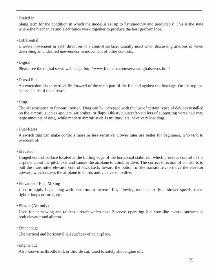
79
• Dialed In
Slang term for the condition in which the model is set up to fly smoothly and predictably. This is the state where the mechanics and electronics work together to produce the best performance.
• Differential
Uneven movement in each direction of a control surface. Usually used when discussing ailerons or when describing an undesired unevenness in movement of other controls.
• Digital
Please see the digital servo web page: http://www.futabarc.com/servos/digitalservos.html
• Dorsal Fin An extension of the vertical fin forward of the main part of the fin, and against the fuselage. On the top, or "dorsal" side of the aircraft.
• Drag The air resistance to forward motion. Drag can be increased with the use of certain types of devices installed on the aircraft, such as spoilers, air brakes, or flaps. Old-style aircraft with lots of supporting wires had very large amounts of drag, while modern aircraft such as military jets, have very low drag.
• Dual Rates
A switch that can make controls more or less sensitive. Lower rates are better for beginners, who tend to overcontrol.
• Elevator
Hinged control surface located at the trailing edge of the horizontal stabilizer, which provides control of the airplane about the pitch axis and causes the airplane to climb or dive. The correct direction of control is to pull the transmitter elevator control stick back, toward the bottom of the transmitter, to move the elevator upward, which causes the airplane to climb, and vice versa to dive.
• Elevator-to-Flap Mixing
Used to apply flaps along with elevators to increase lift, allowing modeler to fly at slower speeds, make tighter loops or turns, etc.
• Elevon (Air only)
Used for delta wing and tailless aircraft which have 2 servos operating 2 aileron-like control surfaces as both elevator and aileron.
• Empennage
The vertical and horizontal tail surfaces of an airplane.
• Engine cut Also known as throttle kill, or throttle cut. Used to safely shut engine off.
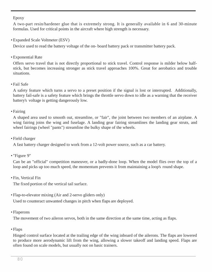
80
Epoxy A two-part resin/hardener glue that is extremely strong. It is generally available in 6 and 30-minute formulas. Used for critical points in the aircraft where high strength is necessary.
• Expanded Scale Voltmeter (ESV)
Device used to read the battery voltage of the on- board battery pack or transmitter battery pack.
• Exponential Rate Offers servo travel that is not directly proportional to stick travel. Control response is milder below half- stick, but becomes increasing stronger as stick travel approaches 100%. Great for aerobatics and trouble situations.
• Fail Safe
A safety feature which turns a servo to a preset position if the signal is lost or interrupted. Additionally, battery fail-safe is a safety feature which brings the throttle servo down to idle as a warning that the receiver battery's voltage is getting dangerously low.
• Fairing
A shaped area used to smooth out, streamline, or "fair", the joint between two members of an airplane. A wing fairing joins the wing and fuselage. A landing gear fairing streamlines the landing gear struts, and wheel fairings (wheel "pants") streamline the bulky shape of the wheels.
• Field charger
A fast battery charger designed to work from a 12-volt power source, such as a car battery.
• "Figure 9" Can be an "official" competition maneuver, or a badly-done loop. When the model flies over the top of a loop and picks up too much speed, the momentum prevents it from maintaining a loop's round shape.
• Fin, Vertical Fin
The fixed portion of the vertical tail surface.
• Flap-to-elevator mixing (Air and 2-servo gliders only) Used to counteract unwanted changes in pitch when flaps are deployed.
• Flaperons The movement of two aileron servos, both in the same direction at the same time, acting as flaps.
• Flaps Hinged control surface located at the trailing edge of the wing inboard of the ailerons. The flaps are lowered to produce more aerodynamic lift from the wing, allowing a slower takeoff and landing speed. Flaps are often found on scale models, but usually not on basic trainers.
81
• Flare
The point during the landing approach in which the pilot gives an increased amount of up elevator to smooth the touchdown of the airplane.
• Flight Box
A special box used to hold and transport all equipment used at the flying field.
• Flight Pack or Airborne Pack All of the radio equipment installed in the airplane, i.e., Receiver, Servos, Battery, Switch harness.
• Floats Long, canoe-shaped structures that allow an airplane to land on water. They are not a part of the aircraft structure, but suspended below the fuselage on struts. Also called "Pontoons".
• Flutter
A phenomenon whereby the elevator or aileron control surface begins to oscillate violently in flight. This can sometimes cause the surface to break away from the aircraft and cause a crash. There are many reasons for this, but the most common are excessive hinge gap or excessive "slop" in the pushrod connections and control horns. If you ever hear a low-pitched buzzing sound, reduce throttle and land immediately.
• Flyback
Decrease in angle held by a servo which is being commanded by an AVCS gyro when the input is released. For example, a rudder servo might be at full deflection when rudder input is held. When the rudder stick is released but the model has not yet turned as far as the AVCS gyro has read your input to tell it to move, the servo will continue to hold input. However, it may "flyback" or decrease the angle at which it is holding slightly. This is perfectly normal.
• Flying Boat
The type of aircraft where the fuselage has the lower portion shaped like a power boat. The plane lands on water directly onto the fuselage. There may be small floats suspended from the wings to keep the plane level when it's in the water.
• Fore, Forward
Towards the front. Used such as "...the forward edge of the rib...", or as in "...with fore and aft movement....”
• Function menu
Used to assign specific features to specific stick, switch, and knob positions. For example, flap control can be moved to a switch by simply changing function assignments.
• Fuselage
The body of an airplane or helicopter.
82
• Gain
Gyro sensitivity. When too low, the tail will not hold position well. When too high, the surface being dampened by the gyro will tend to wag, or hunt for center.
• Glitch
Momentary radio problem that never happens unless you are over trees or a swamp.
• Glow Plug The heat source for igniting the fuel/air mixture in the engine. When starting the engine a battery is used to heat the filament. After the engine is running, the battery can be removed. The wire filament inside the plug is kept hot by the "explosions" in the engine's cylinder. See next heading and "Idle Bar" plug.
• Grease-in
A very smooth, gentle landing without a hint of a bounce.
• Gyro A gyro is an electro-mechanical, or electronic device which aids in the control of an R/C model. The gyro senses motion in one axis, and directs the servo to counter that motion. The sensor, which can be a mechanical gyroscope, or an electronic piezo crystal, detects unwanted movement. The gyro then instructs the servo to counter for that motion. At all times, the radio commands will override the gyro command. The level of control the gyro had is adjusted by the GAIN setting. Mechanical Gyro: uses a mechanical gyroscope (similar to the child's toy) to sense movement. Piezo Gyro: uses a piezo crystal to sense movement. Non-Heading-hold vs. heading hold: A standard (nonHH) gyro senses movement and makes an effort to counter that movement as long as it feels it. Therefore, it is NOT going to return the model to the exact heading prior to the movement. Heading Hold (or AVCS) gyros will lock the model into one position, and accurately correct for movement by sensing rate of change and returning at that same rate. SMM technology: utilizes a microchip to sense movement and provide all readings. Experiences minimal effect from temperature change, commonly known as 'temperature drift' which affects piezo and some mechanical gyros.
• Gyro sensitivity
Used to create stick priority or activate each rate of a dual rate gyro based on stick position. This preprogrammed mix decreases the gain of the gyro directly proportional to the amount of rudder stick given (or steps the gyro down from high to low rate on dual rate gyros.)
• Heading Hold
This describes a type of Gyro which senses rotation, and maintains direction. This is accomplished by sensing the rate of motion, and the time of motion, then compensating for the distance. While this sounds complicated, the effect is that if you have the model dialed in, and point the nose north, with a heading hold gyro on the yaw axis the model will continue to face north until you command it to yaw. See also Heading Lock. This is not recommended for aircraft use while in flight due to the requirement to use YAW (rudder) command to turn the model. Often used for ground use only for perfect take off and landing runs.
83
• Heading Lock
Slang term for Heading Hold Gyro.
• Helicopter Radio A remote control radio system designed specifically for use with helicopter models. The helicopter radio differs from an aircraft radio in a few ways. First, the heli radio needs mixing functions specific to helicopters, and usually a minimum of five channels. Collective mixing for collective pitch helicopters is a necessity. Second is the throttle stick, which is ratcheted in airplane transmitters, will not have the clicking feel on the heli version. This is due to the precise control needed on the heli collective stick to achieve and sustain a controlled hover. The specific radio requirements will vary from user to user, and the parameters used will vary from helicopter to helicopter. Note that many radios produced have both airplane and helicopter programming in a single radio.
• Horizontal Stabilizer
The horizontal tail surface at the back of the fuselage which provides aerodynamic pitch stability to the airplane.
• Hover
To maintain a stationary position in which the model is not climbing, diving, rolling or yawing.
• Hovering offset (Heli programming only) Adjusts the center point of the pitch curves, including the hovering pitch curve, to fine-tune the hovering point when it is not exactly center throttle stick position.
• Hovering pitch (Heli programming only)
This is a pre-programmed hovering-type mix which gives an in-flight adjustment to the pitch curve at and around center stick (or the hovering point if that point is not at center throttle stick, then the center-point of this feature is adjusted with the hovering offset command) to give very fine-tuning for easiest hovering.
• Idle Up
This is a setting on the transmitter which limits the throttle minimum. Particularly useful for FFF and 3D stunt flying.
• Immelmann A maneuver originally used to reverse direction in combat. The airplane noses up and over onto its back. It then rolls upright and continues in the direction opposite to the original direction. It was invented by the World War I German pilot Max Immelmann, whose airplane could perform the maneuver, and others couldn't. It got him out of a lot of trouble in combat until the Allied aircraft designs caught-up and allowed their planes to perform the maneuver, too.
• Inhibit
Makes a feature inactive and unable to be used. When a function is inhibited, it cannot be used even if the assigned switch is moved to the on position. Setting a feature to INH turns off its functionality without losing any settings. Only visible in specific features.

84
• Intake
An air inlet on an aircraft. You can have a carburetor intake, cooling intake, air conditioning intake (on full- size aircraft), and so on. Named because it "takes in" air, and because "intake" is a better-sounding word than "takes in".
• Inverted
To fly a model upside-down.
• Inverted Flight Control Activates inverted flight programming for helis, which reverses the direction of the rudder, pitch and elevator servos, and sets up inverted flight pitch high-side and low-side. Inverted programming is used to allow the radio inputs to be identical to upright flight while the model is inverted. Note: this approach to hovering is seldom used. Instead, idle-ups are used and the modeler learns to understand and respond to the controls' reversal in inverted flight.
• Landing Gear
The assemblies that include the wheels and the wheel struts. The word "gear" is used in the sense of "equipment", as opposed to the "toothed wheel" meaning of "gear". The British call the landing gear the "undercarriage".
• Lateral Balance
The left-right or side-to-side balance of an airplane. An airplane that is laterally balanced will track better through loops and other maneuvers.
• Leading Edge (LE)
The very front edge of the wing or stabilizer. This is the edge that hits the air first.
• Linear Mix Directly proportional.
• Loop A vertical circle in the air. The plane noses up, keeps rotating until it's on its back, and then comes down and around to describe a vertical circle in the air.
• Main Gear
Also Main Landing Gear. The large, heavy-duty landing gear struts and wheels that support most of the weight of the airplane. They are usually under the wing or under the fuselage near the center of the aircraft. Any other landing gear struts and wheels are noticeably smaller.
• Master Mix Mode
Mix option which causes slave channel to operate based on master channel's ATV, not AFR or DIR settings.
• Metal gears
85
Drive gears within a servo which are made of one or multiple metal types. Metal gears tend to wear more rapidly than nylon gears when in the same installation, and so require more frequent service to maintain optimum accuracy; however, metal gears are more durable in the case of severe vibration, flutter, or physical shock.
• Mixing
Allows a single input to control the operation of two or more servos. Simplifies routine flying and allows more involved maneuvers-great for intermediate-advanced fliers. For example, Flap-to-elevator mixing: Most models will change pitch upon deploying flaps (some will climb; others dive). After test flying the model and determining the direction and amount of elevator throw required to correct for this change, a pilot may set a flap-to-elevator mix to compensate. Once the mix is operating properly, when the modeler gives flap control, the radio automatically also gives the proportional amount of elevator throw, keeping the model flat and straight.
• NiCd = Nickel Cadmium battery
Rechargeable batteries which are typically used as power for radio transmitters and receivers.
• Nitro = Nitromethane A fuel additive which increases a model engine's ability to idle low and improves high-speed performance. Ideal nitro content varies from engine to engine. Refer to the engine manufacturer's instructions for best results. Nitro content in fuel is indicated by the percent of the fuel.
• Nose Gear
The strut and wheel that's under the nose of some aircraft.
• Nylon gears Drive gears within a servo are made of nylon. Nylon gears show slower wear than metal gears, but are more prone to failure due to severe vibration, flutter, or physical shock to the servo.
• PPM
Pulse Position Modulation.
• Peak This is the point at which a battery will no longer accept a charge, and converts the energy to heat. This is damaging to the battery pack, and potentially hazardous.
• Peak Charger
This type of charger will eliminate the guesswork. When the battery has reached peak, the charger reverts to a maintenance charge rate, which will not damage the pack.
• Pitch Axis
The airplane axis controlled by the elevator. Pitch is illustrated by holding the airplane at each wingtip. Raising or lowering the nose is the pitch movement. This is how the climb or dive is controlled.
86
Pitch Curve The programming function of the radio which aids in setting the hover point, and end points of the blade pitch in the collective mix. Pitch to rudder (Heli programming only) Also known as a revolution mix or a tail rotor mix, counters the torque caused by adding pitch with opposite direction rudder command to keep the helicopter from rotating or revolving as a result of the increased torque. Not required with the use of a heading-hold gyro, which self-counters the torque-caused movement.
• Pitch Trim
Offsets the entire heli pitch curve, increasing or decreasing responsiveness proportionally at all points.
• Programmable mix (Pmix) Used to cause specific servo responses to specific inputs separate from the basic control set-ups. For example, used to mix 2 servos to operate in tandem to move a rudder on giant scale aircraft, or to mix smoke activation based upon throttle stick position.
• Pull-Pull
A linkage setup using two rods or wires. One is pulled for one direction, the other is pulled for the other.
Push-Pull A linkage setup using two rods. One rod pushes, while the other pulls.
• RPM How fast something turns. It means Revolutions Per Minute. It is both singular and plural.
• Receiver (Rx) The radio unit in the aircraft which receives the transmitter signal and relays the control to the servos. This is somewhat similar to the radio you may have in your family automobile, except the radio in the airplane perceives commands from the transmitter, while the radio in your car perceives music from the radio station.
• Reflex
If a wing has an airfoil that curves down from the high point, and then curves back up, it's said to be "reflexed". Reflex is the size of that reverse curve.
• Reset (Return to default) Used to reset timers, also a model submenu used to reset part or all of a specific model's settings.
• Resonance This is the increased vibration (or amplitude of oscillation) of system when acted upon by a force whose frequency is close to or equal to the normal frequency of the system. When the resonance of many parts of a machine are in synch, the whole machine will vibrate at a greater rate and can be damaged. Resonance can cause difficulties in an aircraft, particularly when using a vibration mount with an improperly balanced
87
propeller/spinner. For helis: Keep in mind that a helicopter has many rotating parts, and they all cause resonance. The helicopter will need to be tuned to reduce the amount of vibration.
• Retract Servo
Specifically used for mechanical retracts. It is a non-proportional servo which only moves 180 degrees. That is to say this servo is either "off" (gear up and fully locked) or "on" (gear down and fully locked). No ATV, EPA, or AST adjustments can be made on these servos because they are not proportional. The linkage must be set up properly to allow this servo to operate at its full range and do its job-securing your model's landing gear in a gear-up or gear-down position.
• Retracts
Short for retractable landing gear. Wheels and struts that fold up into the aircraft to get them out of the airstream and present less resistance to the airflow.
• Revolution Mixing
The function of the radio which mixes throttle to rudder, preventing the rotation of the helicopter during throttle increase or decrease.
• Roll (maneuver)
The aircraft keeps the nose pointed in one direction while it rolls over on its back and then upright again.
• Roll Axis The airplane axis controlled by the ailerons. Roll is illustrated by holding the airplane by the nose and tail. Dropping either wingtip is the roll movement. This is used to bank or turn the airplane. Many aircraft are not equipped with ailerons and the Roll and Yaw motions are controlled by the rudder. This is one reason why most trainer aircraft have a larger amount of dihedral.
• Rudder
Hinged control surface located at the trailing edge of the vertical stabilizer, which provides control of the airplane about the Yaw axis and causes the airplane to Yaw left or right. Left rudder movement causes the airplane to Yaw left, and right rudder movement causes it to Yaw right.
• Rudder Offset
In radios with idle up functions, this specifies the amount of tail rotor pitch in the different idle up conditions.
• Rudder-to-Aileron
Mix used to counteract undesirable roll which often happens with rudder input, especially in knife edge, also called roll coupling.
• Rudder-to-Throttle
This heli mix adds a small amount of throttle to counter the added load on the main gear from increasing the pitch of the tail blades, helping to maintain a constant headspeed during rudder application. (This is a minor
88
effect and is not a critical mix for most helicopters.) Ruddervator Ruddervators are on a v-tail. Both of the ruddervators move up and down for pitch control and both move left or right for yaw control.
• Rx
Abbreviation for receiver.
• SMT = Surface Mount Technology Ultralight, solid-state components which offer greater vibration resistance and reliability.
• Seaplane An airplane that has floats, or pontoons, attached to allow it to land on water.
• Servo The electro-mechanical device which moves the control surfaces or throttle of the aircraft according to commands from the receiver. The radio device which does the physical work inside the aircraft.
• Servo Reversing
Reverses the rotation of a servo with the flip of a switch. Adds ease and flexilibility during installation.
• Servo Output Arm The removable arm or wheel which bolts to the output shaft of a servo and connects to the pushrod.
• Slats Moveable surfaces on the leading edge of the wing that helps airflow in low-speed flight. They enable the wing to fly at lower airspeeds than without them by directing the airflow over the wing and preventing separation of the airflow. Basically, they are retractable slots. All modern jetliners have slats, which open when landing flaps are lowered. Some aircraft intended for very short takeoff and landing have slats that open and close automatically, depending upon airspeed and angle of attack.
• Slip
A maneuver where the airplane's controls are used to make the fuselage fly at an angle to the line of flight. This causes a tremendous increase in drag, and allows an airplane without landing flaps to increase its angle of descent without picking up a lot of speed.
• Slop
Unwanted, excessive free movement in a control system. Often caused by a hole in a servo arm or control horn that is too big for the pushrod wire or clevis pin. This condition allows the control surface to move without transmitter stick movement. Also, see flutter.
• Slot
A specially-shaped slot in the wing just behind the leading edge. This directs airflow from below to the top
89
of the wing, and helps low-speed flight by delaying the stall. Because they are permanently-mounted, they do add drag. See also "Slats"
• Slow Roll
A very slow version of the roll.
• Snap Roll A type of rolling maneuver that is very quick and violent. It's basically a spin where the flight path is in any direction chosen by the pilot. Improper speed control during a landing approach can also make the model snap over on one wing and enter a spin. Since it's close to the ground, there's not enough room to recover, and a crash results.
• Snap Roll Switch
Combines rudder, elevator and aileron movement to cause the aircraft to snap or spin on the flip of a switch.
• Solo Your first totally unassisted flight that results in a controlled landing.
• Span, also "Wingspan" The widest straight-line distance between the two wingtips.
• Speed Brakes Large panels that fold out of the aircraft structure to provide a lot of extra drag to the air. They are not part of the wing structure, but are usually mounted on the fuselage. Military jets most often have speed brakes, which fold out of the fuselage. Some airliners use spoilers as speed brakes when at altitude.
• Speed Flap
The middle control surface on a 6-trailing-edge-surface glider or the inboard control surface on a 4-surface glider.
• Spin
A maneuver where at least one wing is stalled and the two wings are operating at very different angles of attack. This causes the airplane to rotate around its middle while it descends at a high rate of speed. When it's done on purpose, it is a precision maneuver, with the pilot trying to get the airplane to rotate an exact number of turns from entry to exit. When it's done accidentally, it can easily result in a crash. Many models crash when the pilot enters an accidental spin too close to the ground. This is caused by improper speed control during the landing approach.
• Spinner
The bullet-shaped fairing on the nose of the airplane around the propeller. This smooths the airflow around the propeller hub and also makes the airplane looks much better.
90
• Split-S
Basically a reverse Immelmann. The aircraft rolls onto its back, and then the nose comes down to finish a 1I2-loop. The direction of flight is changed 180o.
• Spoiler(s) Control surfaces on the wing that destroy lift. They "spoil" it. They are used on sailplanes because they can steepen the very flat glide of the aircraft, which makes landings much easier. On full-size aircraft, spoilers are also used to kill lift on landing to make sure the airplane is firmly on the ground. They also add a lot of drag to help with aerodynamic braking.
• Stabilator
Stabilizer+elevator, also called full-flying tail. Stabilizer incidence controlled by pilot in lieu of an elevator.
• Stall What happens when the angle of attack is too great to generate lift regardless of airspeed. (Every airfoil has an angle of attack at which it generates maximum lift—the airfoil will stall beyond this angle).
• Stick setting
Used to assign the specific feature(s) to a particular gimbals' movement.
• Strut Basically this is a supporting member. A wing strut supports the wing, and goes from the fuselage to the wing. Cabane struts are on biplanes, and support the upper wing over the fuselage. A landing gear strut is the portion that holds the wheel assembly to the airplane, and away from the wing or fuselage.
• Sub-Trim
This is a trim function on many computer radios, allowing trim function during set-up, and still allowing the full trim function in flight.
• Swashplate adjustment (Heli programming only)
This feature includes swash-to-throttle mixing, used to add throttle during cyclic commands for constant engine RPM. It also includes swash rotation, used to correct for a model whose set-up has the swash plate shifted a certain angle from the pre-defined swash plate types in the model menu (SWSH) or to fine-tune roll or looping maneuvers due to rotor blade phasing differences.
• Swashplate type (Heli programming only)
Selects specific helicopter swash plate geometry, such as "CCPM," which uses a 4-servo swash plate set- up. Swash plate rotation can then be adjusted in SWSH in the condition menu if your helicopter's specific geometry does not match the positioning of the stock swash types.
• Tachometer
An optical sensor designed specifically to count light impulses through a turning propeller and read out the engine RPM.
91
• Taildragger
The nickname of an airplane that sits on its tail with the two main wheels in front and a tailwheel in the rear.
• Tailskid On old World War I type aircraft, or pioneer-type aircraft, there was no tailwheel. A wooden skid was used to support the tail of the airplane. While this helps slow the airplane during landing, it is useless as an aid to steering on the ground. The real aircraft with tailskids had to be maneuvered on the ground by ground crews, who put the tail on a small cart and towed the airplane where they wanted it. For small distances, the tail was picked-up by hand and the airplane pushed into position by the ground crew.
• Tailwheel
The small wheel at the tail of the airplane. This is found on the type of airplane that have the two large wheels in the front, and the small one in the rear. The airplane sits on its tail.
• Throttle
The control that allows the pilot to change the speed of the engine.
• Throttle Curve The programming function of the radio which allows throttle operation to be adjusted to meet the modeler's specific needs at various points along the throttle movement.
• Throttle Hold
A radio function which locks the throttle at a fixed point while a switch is activated. This function is used to hold the throttle in an idle. Useful when starting, as well as for autorotations.
• Thrust
The forward force provided by the airplane's engine. This is the force that drives the airplane forward.
• Torque The force which tends to cause rotation.
• Trailing Edge (TE) The rearmost edge of the wing or stabilizer.
• Trainer Airplane A model designed to be inherently stable and fly at low speeds, to give first-time modelers time to think and react as they learn to fly.
• Trainer System
Allows trainer to link radios with a student via a cord, and to instantly take control of student's craft in- flight.
92
• Transmitter (Tx)
The hand-held radio controller. This is the unit that sends out the commands that you input. Tricycle Gear The landing gear arrangement where the airplane has main gear and a nose gear. Trim menu Used to memorize current digital trim positions, set trim type, % of trim delay when switching from condition to condition, sound on or off when trimmers used, rate of trim response at 2 different lengths of time held, and having trims affect all conditions or only the current condition. For example, store trim positions to memory once model is perfectly trimmed. Adjust CG and re-fly, re-trim. Amount of trim change caused by adjustment to aircraft is now easily measured. To activate additional features of trim menu, select the specific trimmer and adjust as desired.
• Tx
Abbreviation for transmitter.
• Undercamber This means that the lower surface of the wing has a hollow curve when observed from front to back. A thin wing with a high camber will be undercambered.
• V-tail model Mixing (Air and gliders only)
Used on a V-tail model to have 2 servos operate 2 control surfaces as both rudder and elevator.
• Ventral Fin A small vertical surface on the bottom of the aft fuselage. Usually a long, slim triangle that is narrow at the front, and widens toward the rear. It usually ends at the rudder hinge line.
• Vertical Fin
The non-moving surface that is perpendicular to the horizontal stabilizer and provides yaw stability. This is the surface to which the rudder attaches.
• Washout
An intentional twist in the wing, causing the wing tips to have a lower angle of attack than the wing root. In other words, the trailing edge is higher than the leading edge at the wing tips. Washout helps prevent tip stalls, and helps the "PT" family of trainers recover, hands-off, from unwanted spiral dives.
• Wheel Pants
The large fairings used to streamline the wheels of an aircraft that has non-retracting or "fixed" landing gear (so-called because it's "fixed" in place).
• Wing The main lifting surface of an airplane.

93
• Winglet
A small vertical surface at the tips of the wings. They help direct the turbulent airflow that all wings have at the tips. They make the wings more efficient.
• Yaw
The nose-left and nose-right movement of the airplane. This is controlled by the rudder.
• Yaw Axis The airplane axis controlled by the rudder. Yaw is illustrated by hanging the airplane level by a wire located at the center of gravity. Left or right movement of the nose is the Yaw movement.
FUTABA CORPORATION Phone: +81 475 32 6982, Facsimile: +81 475 32 6983 1080 Yabutsuka, Chosei-mura, Chosei-gun, Chiba-ken, 299-4395, Japan
©FUTABA CORPORATION 2011, 02 (1)

各式遙控器中英對照表
A
AB.ABK.ABRAKE-------阻流閥。滑翔機之 3CH.阻流閥。減速用。 ACCE -----------------------加速。與專用汽化器使用之混合(MIXING)。 補正混控修正用。 ACRO ----------------------飛機模式類型。 ACT -----------------------機能動作 (使用時程式機能顯示)。 AI.AIL ----------------------副翼動作 (Futaba 在 1CH 動,JR 在第 2 動)。 AI-DIF ----------------------副翼差異可使左右副翼動作發動之機能調整。 AIL-FL----------------------副翼→襟翼。副翼→襟翼混合。(飛機用)。 ALL ------------------全部。 ALVATR -------------------副翼和升降舵。能產生組合副翼與升降舵之動作的混合一起使用連動。 ATL ------------------------只在油門低速產生微調動作之機能。 ATV ------------------------可單獨調整伺服器動作之機能左邊或右邊%比大小向量調整
B BFLY -------------------蝶形(V 型飛機)混合滑翔機之制動混合。
C
CH1 -------------------頻道 1(Futaba 為左右、JR 為油門) CH2 -------------------頻道 2(Futaba 為上下、JR 為左右) CH3 -------------------頻道 3(Futaba 為油門、JR 為上下) CH4 -------------------頻道 4(Futaba 為尾舵、JR 為尾舵)-直升機用時為接陀螺儀 RUDD 線。 CH5 -------------------頻道 5(Futaba 為直升機陀螺儀用飛機為-收腳、JR 為收腳或放鞭炮用)。 CH6 AUX1 ---------------頻道 6(Futaba 為飛機襟翼、升機為螺旋漿 、JR 為飛機襟翼、直升機為 螺旋漿用)。 CH7 AUX2 ---------------頻道 7(Futaba 為飛機阻流閥減速用、JR 又可-為陀螺儀用)。 CH8 AUX3 --------------頻道 8(同上功能或 B‧BCLL 找機子用)。 CH9 AUX4 -------------頻道 9(同上功能或射影機用)。 CH10 AUX5 --------------頻道 9(同上功能或用電源指示燈用)。 CNTR ----------------中央。開關的中央 COPY -----------------複寫。數據機之複寫(可程式複製或傳輸)。 CROSS -----------------交叉位置。使用開關的背面飛行機能使用時,低側螺矩交叉之處(Futaba 特殊功能使開關變換位置)。
D

95
D/R- ----------------A、E、R 舵腳轉換機能(大動作小動作比率調整)

DATARST -------------數據復位(RESET 將設定好的記憶清除)。 DELAY --------------延遲回路 DISP ----------------顯示。微調之顯示方法。 DOWN ----------------下側。
E EG/S -------------------引擎啟動裝置。引擎啟動裝置開關機能
ELELE ------------------升降舵,2CH 動(JR 為第 3 動)。 ELEVON ------------------副翼升降舵組合副翼與升降舵之動作的機能調整。 ERROR -------------------錯誤當機。(請在從開)。 ERROR BACKUP -----支持系統錯誤,設定之數據全部消失當出現此訊息時請立即送修。(記憶電 池沒電了)。 ERROR LOW BATT---低電池錯誤,電池電壓下降。(請自行充電即可)。 ERROR MDL SEL ------模型挑選錯誤,資料庫之錯誤顯示。(程式錯誤)。 EXP- ---------------對應搖桿動作之伺服器動作。指數感度快慢設定。 EXT-MEM ------------擴張記憶。外部記憶。(Futaba 有,JR 沒有)。
F
F/S ------------------安全控制裝置。正常電波無法接收信號時之各伺服器的動作位置設定。(防止 干擾時所設定用)。 FL,FLP ------------------襟翼 6CH。(JR 為陀螺儀用)。 FLP→A1 ----------------襟翼→副翼。襟翼→副翼混合。(飛機用)。 FLPRON ----------------副襟翼。使副翼擁有襟翼功能之機能。 FLPTRM ----------------襟翼微調。襟翼之微調功能。(修正用)。 FREE ----------------自由。無設定安全裝置開關。(避免功能開關因撥到而設定的保護開關裝置)。
G
GE,GEA -----------------齒輪。第 5CH。(飛機收腳用,直升機 F 陀螺儀用)。 GLID1FLP ----------------滑翔機、飛機-1 襟翼。滑翔機用之混合左右各一伺服機。 GLID2FLP ---------------滑翔機、飛機-2 襟翼。滑翔機用之混合。 GY,GYR ------------------陀螺儀 5CH。(收信機輸出控制用)。
H HELISWH1 ---------------一般直升機用混合型。
HELISWH2 ---------------特殊 CCPM 直升機用混合型。 HLDP ----------------保持位置油門保持時之油門固定不動位置。 HOLD ------------------保持進行自轉著陸時之油門保持(SLOW)低速機能。 HOV-PI -----------------停懸螺距懸停遙桿在中立時之螺距旋鈕微調機能。
HOV-TH -----------------停懸油門懸停遙桿在中立時之油門旋鈕微調機能。
I
IDL-1 --------------------定速切換 1 時翻跟斗、540 度旋轉等的上空飛行之設定。(引擎定速特技第 一段設定機能)。 IDL-2 --------------------定速切換 2。翻滾表演等上空飛行的設定。(例 3D 等動作)。 IDL-DN --------------------定速切換利用開關使引擎轉速下降之機能。 INH --------------------INHIBIT。機能停止。(功能設定沒用時所顯示)。 INIT --------------------INTIALIZE。資料庫之格式化。(重新,此功能少-用必免當機修理)。 INVERT,INVR ------------INVERTED。使用開關,背面飛行機能。(倒飛和正飛飛行操控方向同。(3D 飛行則操控相反)。
L L/D --------------------LEFT/DOWN 快速翻滾方向切換向下。
L/U --------------------LEFT/UP 快速翻滾方向切換向上。 LIN ---------------------LINEAR。直線的。以油門遙桿操作混合之方向。 LINK -------------------連動 程式混合中之機能。(一次同時進行兩個伺服之動作,例如飛行動作補 正)。 LOCK --------------------鎖住。不能使機能運作。
M
MANU -------------------手動。以開關操作。(不用進入程式內設定)。 MOD --------------------調變。變調之信號型式。(PCM、PPM 之類)。 MODEL -------------------模型。模型機能。(多台模型記憶功能切換之用)。
N NAME ---------------------模型機能之名稱。(可將各設定記憶好的程式加以命名)。
NEGA ----------------------NEGATIVE。畫面之微調顯示以明暗表示 NEXT ← → ---------------有次畫面。(程式內,程式再進入指示)。 NORM -------------------標準飛行。停懸等一般飛行之基本設定。(初學者專用)。 NULL ---------------------零、無。(表示此功能開關設定無)。
O OFF - -------------------程式功能機能 OFF 沒開或電源開關 OFF。
OFST-1 --------------------OFF-SET1。利用開關之微調補正 OFST-2 --------------------OFF-SET2。利用開關之微調補正 OK? --------------------可以嗎?(執行程式功能前的確認)。 ON -----------------------程式功能機能 OFF 沒開或電源開關 ON。

P PARA --------------------參數。參數機能。
PCM ---------------------PULSM CODE MODUL-ATION 的略稱。脈波電碼調節。(變調電波之信號型 式)。 PI-PIT --------------------螺距。6CH。(直升機第五伺服機螺旋漿動作使用)。 PI-CRV --------------------螺距曲線。以五個螺距點之動作所作之曲線調整。 PI-TRM -------------------螺距微調。(可做飛行中的修正調整)。 PMIX --------------------任意頻道間之混合。(伺服機的混合連動的意思)。 POS ----------------------位置。場所。(所設定的開關位置可任意的變換位置 Futaba 才有的功能)。 POSI ----------------------POSITIVE。程式功能畫面之微調顯示是以白底點黑線的方式呈現目前所在 執行的程式指示。 PPM ----------------------脈波位置調節之略稱(變調之信號型式)。
R
R/D ----------------------右下。快速轉動方向轉換補正調整。 R/U ----------------------右上。快速轉動方向轉換補正調整。 REVERS,REV --------------正反向。伺服器之動作方向變換機能調整。 REVOLU ------------------抑制主旋翼之反動旋轉的混合尾舵機能力補正使得上升或下降時直升機 不會產生旋轉偏移現像。 RU,RUD ------------------方向舵,第 4CH。(接陀螺儀控制尾部)。
S SAFE -----------------------安全裝置開關。
SEL ------------------------選擇。模型之選擇。(切換顯示功能)。 SEL ------------------------設定。決定。(切換設定功能通用字語)。 SNAP,SNP -----------------快速滾動。以開關操作快速滾動的機能。 SPEED -------------------速度。速度混合。 START ------------------爬昇功能。爬昇混合。 STEP -------------------步近。微調的不進量。(數位式可調整大小量)。 STICK,STK ------------桿。 SUBTRM ---------------程式內伺服機個別之中心點調整機能。(內中心點微調,IDL-1、IDL2 可再 做調整)。 SW ------------------------開機。(電源開關)。
T TH,THR --------------------油門。(Futaba 第 3CH、JR 為第 1CH)。
TH-CRV --------------------油門曲線。以五個油門點之動作所作之曲線調整。
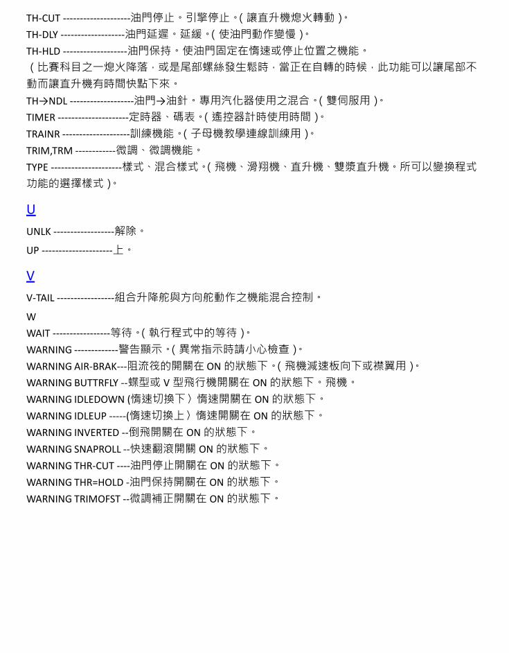
TH-CUT --------------------油門停止。引擎停止。(讓直升機熄火轉動)。 TH-DLY -------------------油門延遲。延緩。(使油門動作變慢)。 TH-HLD -------------------油門保持。使油門固定在惰速或停止位置之機能。 (比賽科目之一熄火降落,或是尾部螺絲發生鬆時,當正在自轉的時候,此功能可以讓尾部不 動而讓直升機有時間快點下來。 TH→NDL -------------------油門→油針。專用汽化器使用之混合。(雙伺服用)。 TIMER ---------------------定時器、碼表。(遙控器計時使用時間)。 TRAINR --------------------訓練機能。(子母機教學連線訓練用)。 TRIM,TRM ------------微調、微調機能。 TYPE ---------------------樣式、混合樣式。(飛機、滑翔機、直升機、雙漿直升機。所可以變換程式 功能的選擇樣式)。
U UNLK ------------------解除。
UP ---------------------上。
V V-TAIL -----------------組合升降舵與方向舵動作之機能混合控制。
W WAIT -----------------等待。(執行程式中的等待)。 WARNING -------------警告顯示。(異常指示時請小心檢查)。 WARNING AIR-BRAK---阻流筏的開關在 ON 的狀態下。(飛機減速板向下或襟翼用)。 WARNING BUTTRFLY --蝶型或 V 型飛行機開關在 ON 的狀態下。飛機。 WARNING IDLEDOWN (惰速切換下〉惰速開關在 ON 的狀態下。 WARNING IDLEUP -----(惰速切換上〉惰速開關在 ON 的狀態下。 WARNING INVERTED --倒飛開關在 ON 的狀態下。 WARNING SNAPROLL --快速翻滾開關 ON 的狀態下。 WARNING THR-CUT ----油門停止開關在 ON 的狀態下。 WARNING THR=HOLD -油門保持開關在 ON 的狀態下。 WARNING TRIMOFST --微調補正開關在 ON 的狀態下。


![IMQ[Z - Wing On Travel...^:/RmW>Zdr\? qWHc5ZnA6 qWHc5Zi6 5g,aU]-ofZ.F^>]N2rAUy 5z@===_6 9V:8A[kc @6 6j,WT/aN 6j,WT/aN [YdFc6 Fc6 YHOKU=CXB](https://static.fdocuments.in/doc/165x107/60cb98904212e375db272fc5/imqz-wing-on-travel-rmwzdr-qwhc5zna6-qwhc5zi6-5gau-ofzfn2rauy.jpg)