6968020110 1V2 ART Plus ENG 100203 - akapela.ru Art Plus Operators Manual.pdf · 4.9 TMJ...
32
Blue X Imaging Srl Via Idiomi 1/8-33 20090 Assago ITALY e-mail [email protected] for Oy AJAT Ltd Tietotie 3 FIN-02150 Espoo Finland [email protected] ART Plus Dental Panoramic X-Ray Operator’s Manual
-
Upload
nguyenthuan -
Category
Documents
-
view
223 -
download
1
Transcript of 6968020110 1V2 ART Plus ENG 100203 - akapela.ru Art Plus Operators Manual.pdf · 4.9 TMJ...
Blue X Imaging Srl Via Idiomi 1/8-33 20090 Assago ITALY e-mail [email protected] for Oy AJAT Ltd Tietotie 3 FIN-02150 Espoo Finland [email protected]
ART Plus Dental Panoramic X-Ray
Operator’s Manual
ART Plus – Operator’s Manual
2/32 6968020110 Version 2.0
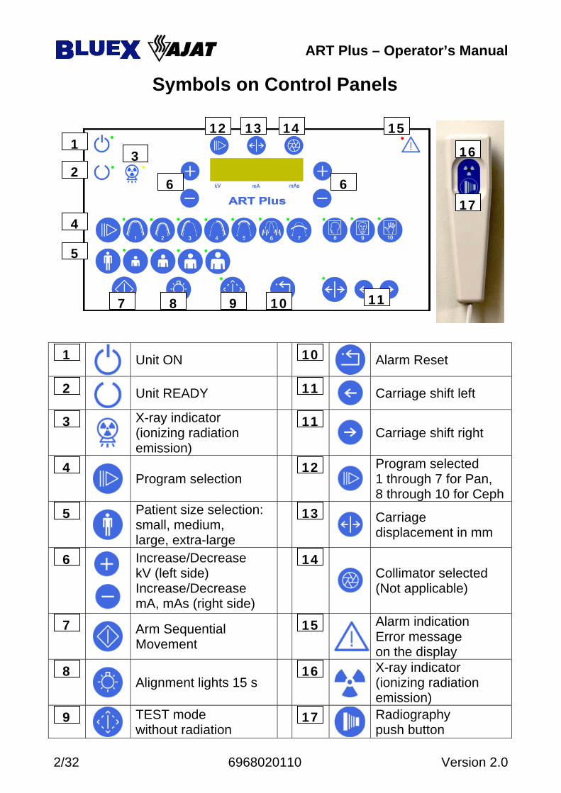
Unit ON Alarm Reset
Unit READY Carriage shift left
X-ray indicator (ionizing radiation emission)
Carriage shift right
Program selection Program selected 1 through 7 for Pan, 8 through 10 for Ceph
Patient size selection: small, medium, large, extra-large
Carriage displacement in mm
Increase/Decrease kV (left side) Increase/Decrease mA, mAs (right side)
Collimator selected (Not applicable)
Arm Sequential Movement
Alarm indication Error message on the display
Alignment lights 15 s X-ray indicator (ionizing radiation emission)
TEST mode without radiation Radiography
push button 17 9
16 8
15 7
14 6
13 5
12 4
11 3
11 2
10 1
1
2 3
4
5
6
7 8 9 11 10
12 13 14 15
6
16
17
Symbols on Control Panels
ART Plus – Operator’s Manual
Version 2.0 6968020110 3/32
Manufactured by
Blue X Imaging S.r.l. Via Mario Idiomi 1/8-33 20090 Assago ITALY
tel.+39.0245712171 - fax +39.0245703385 e-mail [email protected] - www.bluex.it
for
Oy AJAT Ltd Tietotie 3
FIN-02150 ESPOO FINLAND Tel: +358-40-568 1865 - Fax: +358-9-4559 0753
e-mail [email protected] - www.ajat.fi
ART Plus Dental Panoramic X-ray
Operator’s Manual – English Edition
Version 2.0 February 2010
Printed 2/3/2010 8:33:00 AM Code 69 680 20110
ART Plus – Operator’s Manual
4/32 6968020110 Version 2.0
1. INTRODUCTION ...................................................................................... 5
1.1 Purpose .............................................................................................. 5 1.2 Product Documentation ..................................................................... 5 1.3 Notice to installers ............................................................................. 6 1.4 Notice to Users .................................................................................. 6 1.5 Warning ............................................................................................. 6 1.6 Safety Issues ...................................................................................... 7
2. GENERAL .................................................................................................. 8 2.1 Indications for Use ............................................................................ 8 2.2 Theory of Operation .......................................................................... 9 2.3 Control panels ................................................................................. 10 2.4 Functions ......................................................................................... 11 2.5 Panoramic Magnification Factor ..................................................... 12 2.6 Provisions for safety ........................................................................ 13
3. DIGITAL IMAGING ............................................................................... 14 3.1 System Architecture ........................................................................ 14 3.2 Computer Specifications ................................................................. 14 3.3 AJAT Panoramic Imaging ............................................................... 15
4. PANORAMIC RADIOLOGY .................................................................. 16 4.1 Panoramic Programs ....................................................................... 16 4.2 Trial Session .................................................................................... 16 4.3 Technique Factors ........................................................................... 17 4.4 Positioning Accessories ................................................................... 17 4.5 The Aiming Lights .......................................................................... 18 4.6 Resetting Carriage in Patient Entry Position ................................... 18 4.7 Patient Positioning .......................................................................... 19 4.8 Adjustment of displayed layer ......................................................... 21 4.9 TMJ projections .............................................................................. 22 4.10 Maxillary Sinuses ............................................................................ 22 4.11 Panoramic Exposure ........................................................................ 23
5. MAINTENANCE ..................................................................................... 24 5.1 Cleaning .......................................................................................... 24 5.2 Disinfecting ..................................................................................... 24 5.3 Servicing ......................................................................................... 24 5.4 Disposing of Obsolete Equipment ................................................... 25
6. CLASSIFICATION .................................................................................. 25 Appendix A Error Messages ............................................................................. 26 Appendix B Icons .............................................................................................. 27 Appendix C Technical Data .............................................................................. 28 Appendix D Labels ........................................................................................... 29 Appendix E Cooling Curves ............................................................................. 30 Appendix F Fuse Table .................................................................................... 31
Table of Contents
ART Plus – Operator’s Manual
Version 2.0 6968020110 5/32
1. INTRODUCTION
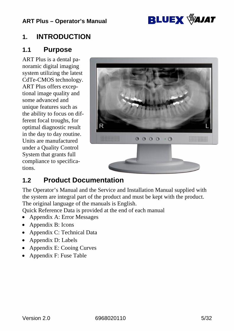
1.1 Purpose ART Plus is a dental pa-noramic digital imaging system utilizing the latest CdTe-CMOS technology. ART Plus offers excep-tional image quality and some advanced and unique features such as the ability to focus on dif-ferent focal troughs, for optimal diagnostic result in the day to day routine. Units are manufactured under a Quality Control System that grants full compliance to specifica-tions.
1.2 Product Documentation The Operator’s Manual and the Service and Installation Manual supplied with the system are integral part of the product and must be kept with the product. The original language of the manuals is English. Quick Reference Data is provided at the end of each manual • Appendix A: Error Messages • Appendix B: Icons • Appendix C: Technical Data • Appendix D: Labels • Appendix E: Cooing Curves • Appendix F: Fuse Table
ART Plus – Operator’s Manual
6/32 6968020110 Version 2.0
1.3 Notice to installers Obligations of the installer are: • To make sure that the line voltage specified be the Manufacturer of the
equipment is available and within the specified range. • For safety reasons verify that a proper switch is available to disconnect the
equipment from mains when needed during installation • To install and test the equipment with due diligence according to the
installation instructions from the Manufacturer.
1.4 Notice to Users It is the responsibility of the User: • To use the system following the instructions and recommendations contained
in the Operator’s Manual. • To maintain the equipment in compliance by following the
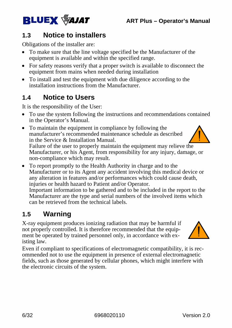
manufacturer’s recommended maintenance schedule as described in the Service & Installation Manual. Failure of the user to properly maintain the equipment may relieve the Manufacturer, or his Agent, from responsibility for any injury, damage, or non-compliance which may result.
• To report promptly to the Health Authority in charge and to the Manufacturer or to its Agent any accident involving this medical device or any alteration in features and/or performances which could cause death, injuries or health hazard to Patient and/or Operator. Important information to be gathered and to be included in the report to the Manufacturer are the type and serial numbers of the involved items which can be retrieved from the technical labels.
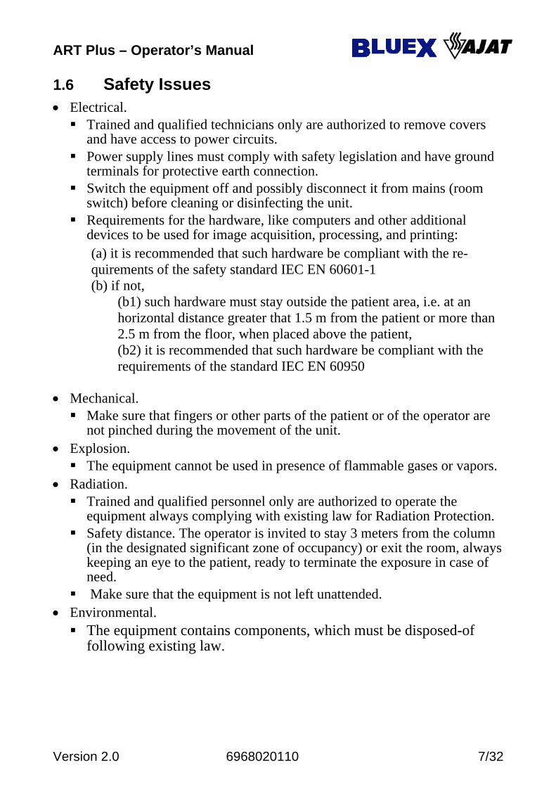
1.5 Warning X-ray equipment produces ionizing radiation that may be harmful if not properly controlled. It is therefore recommended that the equip-ment be operated by trained personnel only, in accordance with ex-isting law. Even if compliant to specifications of electromagnetic compatibility, it is rec-ommended not to use the equipment in presence of external electromagnetic fields, such as those generated by cellular phones, which might interfere with the electronic circuits of the system.
ART Plus – Operator’s Manual
Version 2.0 6968020110 7/32
1.6 Safety Issues • Electrical.
Trained and qualified technicians only are authorized to remove covers and have access to power circuits.
Power supply lines must comply with safety legislation and have ground terminals for protective earth connection.
Switch the equipment off and possibly disconnect it from mains (room switch) before cleaning or disinfecting the unit.
Requirements for the hardware, like computers and other additional devices to be used for image acquisition, processing, and printing:
(a) it is recommended that such hardware be compliant with the re-quirements of the safety standard IEC EN 60601-1
(b) if not, (b1) such hardware must stay outside the patient area, i.e. at an
horizontal distance greater that 1.5 m from the patient or more than 2.5 m from the floor, when placed above the patient,
(b2) it is recommended that such hardware be compliant with the requirements of the standard IEC EN 60950
• Mechanical.
Make sure that fingers or other parts of the patient or of the operator are not pinched during the movement of the unit.
• Explosion. The equipment cannot be used in presence of flammable gases or vapors.
• Radiation. Trained and qualified personnel only are authorized to operate the
equipment always complying with existing law for Radiation Protection. Safety distance. The operator is invited to stay 3 meters from the column
(in the designated significant zone of occupancy) or exit the room, always keeping an eye to the patient, ready to terminate the exposure in case of need.
Make sure that the equipment is not left unattended. • Environmental.
The equipment contains components, which must be disposed-of following existing law.
ART Plus – Operator’s Manual
8/32 6968020110 Version 2.0
1
2
3
4 4
2. GENERAL
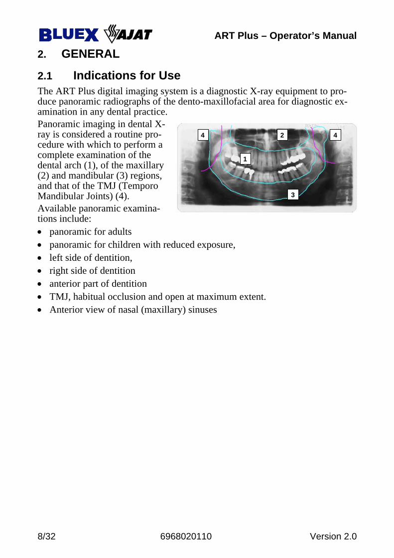
2.1 Indications for Use The ART Plus digital imaging system is a diagnostic X-ray equipment to pro-duce panoramic radiographs of the dento-maxillofacial area for diagnostic ex-amination in any dental practice. Panoramic imaging in dental X-ray is considered a routine pro-cedure with which to perform a complete examination of the dental arch (1), of the maxillary (2) and mandibular (3) regions, and that of the TMJ (Temporo Mandibular Joints) (4). Available panoramic examina-tions include: • panoramic for adults • panoramic for children with reduced exposure, • left side of dentition, • right side of dentition • anterior part of dentition • TMJ, habitual occlusion and open at maximum extent. • Anterior view of nasal (maxillary) sinuses
ART Plus – Operator’s Manual
Version 2.0 6968020110 9/32
M
L
N K
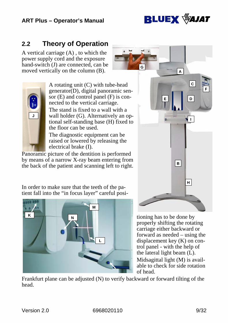
2.2 Theory of Operation A vertical carriage (A) , to which the power supply cord and the exposure hand-switch (J) are connected, can be moved vertically on the column (B).
A rotating unit (C) with tube-head generator(D), digital panoramic sen-sor (E) and control panel (F) is con-nected to the vertical carriage. The stand is fixed to a wall with a wall holder (G). Alternatively an op-tional self-standing base (H) fixed to the floor can be used. The diagnostic equipment can be raised or lowered by releasing the electrical brake (I).
Panoramic picture of the dentition is performed by means of a narrow X-ray beam entering from the back of the patient and scanning left to right. In order to make sure that the teeth of the pa-tient fall into the “in focus layer” careful posi-
tioning has to be done by properly shifting the rotating carriage either backward or forward as needed – using the displacement key (K) on con-trol panel - with the help of the lateral light beam (L). Midsagittal light (M) is avail-able to check for side rotation of head.
Frankfurt plane can be adjusted (N) to verify backward or forward tilting of the head.
A
B
C
D E
G
H
J I
F
ART Plus – Operator’s Manual
10/32 6968020110 Version 2.0
13
4
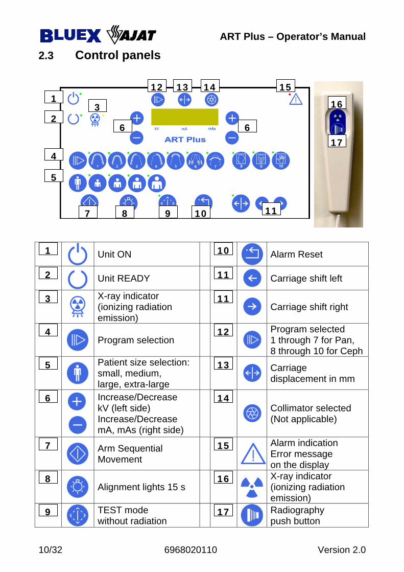
2.3 Control panels
Unit ON Alarm Reset
Unit READY Carriage shift left
X-ray indicator (ionizing radiation emission)
Carriage shift right
Program selection Program selected 1 through 7 for Pan, 8 through 10 for Ceph
Patient size selection: small, medium, large, extra-large
Carriage displacement in mm
Increase/Decrease kV (left side) Increase/Decrease mA, mAs (right side)
Collimator selected (Not applicable)
Arm Sequential Movement
Alarm indication Error message on the display
Alignment lights 15 s X-ray indicator (ionizing radiation emission)
TEST mode without radiation Radiography
push button 17 9
16 8
15 7
14 6
13 5
12 4
11 3
11 2
10 1
1
2 3
4
5
6
7 8 9 11 10
12 13 14 15
6
16
17
ART Plus – Operator’s Manual
Version 2.0 6968020110 11/32
2.4 Functions
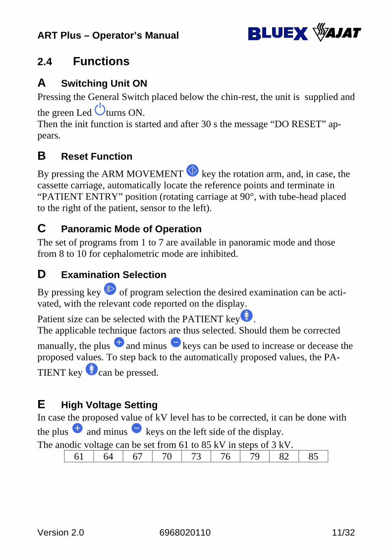
A Switching Unit ON Pressing the General Switch placed below the chin-rest, the unit is supplied and the green Led turns ON. Then the init function is started and after 30 s the message “DO RESET” ap-pears.
B Reset Function
By pressing the ARM MOVEMENT key the rotation arm, and, in case, the cassette carriage, automatically locate the reference points and terminate in “PATIENT ENTRY” position (rotating carriage at 90°, with tube-head placed to the right of the patient, sensor to the left).
C Panoramic Mode of Operation The set of programs from 1 to 7 are available in panoramic mode and those from 8 to 10 for cephalometric mode are inhibited.
D Examination Selection
By pressing key of program selection the desired examination can be acti-vated, with the relevant code reported on the display. Patient size can be selected with the PATIENT key . The applicable technique factors are thus selected. Should them be corrected manually, the plus and minus keys can be used to increase or decease the proposed values. To step back to the automatically proposed values, the PA-TIENT key can be pressed.
E High Voltage Setting In case the proposed value of kV level has to be corrected, it can be done with the plus and minus keys on the left side of the display. The anodic voltage can be set from 61 to 85 kV in steps of 3 kV. 61 64 67 70 73 76 79 82 85
ART Plus – Operator’s Manual
12/32 6968020110 Version 2.0
F Anodic Current Setting In case the proposed value of mA level has to be corrected, it can be done with the plus and minus keys on the right side of the display. The anodic current can be set from 4 to 10 mA. 4.0 5.0 6.3 8.0 10
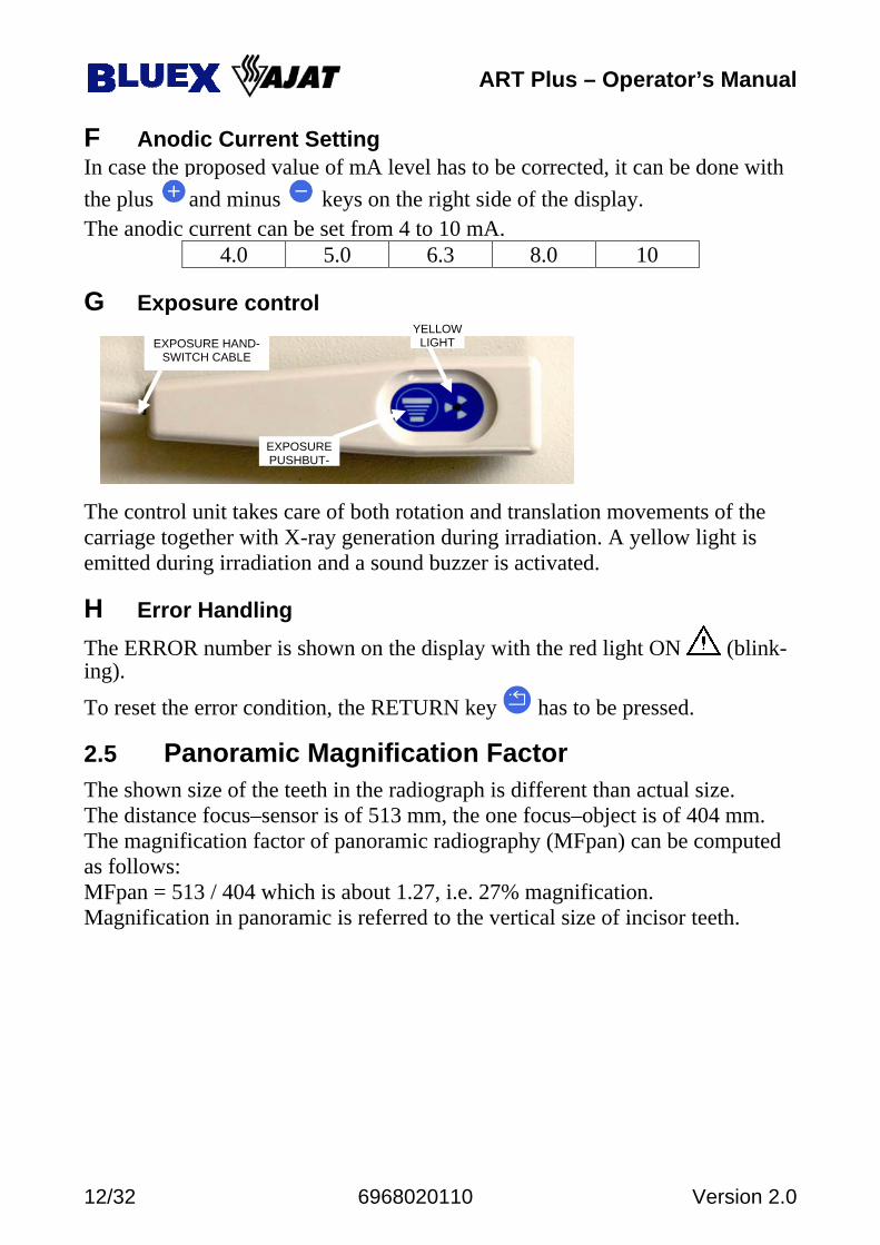
G Exposure control The control unit takes care of both rotation and translation movements of the carriage together with X-ray generation during irradiation. A yellow light is emitted during irradiation and a sound buzzer is activated.
H Error Handling The ERROR number is shown on the display with the red light ON (blink-ing).
To reset the error condition, the RETURN key has to be pressed.
2.5 Panoramic Magnification Factor The shown size of the teeth in the radiograph is different than actual size. The distance focus–sensor is of 513 mm, the one focus–object is of 404 mm. The magnification factor of panoramic radiography (MFpan) can be computed as follows: MFpan = 513 / 404 which is about 1.27, i.e. 27% magnification. Magnification in panoramic is referred to the vertical size of incisor teeth.
YELLOWLIGHT
EXPOSURE PUSHBUT-
EXPOSURE HAND-SWITCH CABLE
ART Plus – Operator’s Manual
Version 2.0 6968020110 13/32
2.6 Provisions for safety Correct status of the unit and proper adjustment of movable parts are indicated by the READY light . If system is not in the READY condition, press the ARM MOVEMENT key
to initialize the system. After each exposure the unit enters a waiting period to cool down. During the waiting time the READY indicator blinks and exposures cannot be made. Count down register is displayed. If a failure happens when system is switched ON or during exposure, the ER-ROR indicator will light up. This indicator is also lit for incorrect operations (e.g. push-button released dur-ing exposure). The number displayed represents the error code (see appendix A). Press the ALARM RESET key to acknowledge and cancel the error indica-tion.
ART Plus – Operator’s Manual
14/32 6968020110 Version 2.0
3. DIGITAL IMAGING
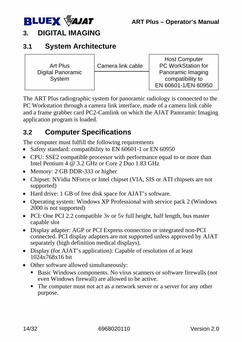
3.1 System Architecture The ART Plus radiographic system for panoramic radiology is connected to the PC Workstation through a camera link interface, made of a camera link cable and a frame grabber card PC2-Camlink on which the AJAT Panoramic Imaging application program is loaded.
3.2 Computer Specifications The computer must fulfill the following requirements • Safety standard: compatibility to EN 60601-1 or EN 60950 • CPU: SSE2 compatible processor with performance equal to or more than
Intel Pentium 4 @ 3.2 GHz or Core 2 Duo 1.83 GHz • Memory: 2 GB DDR-333 or higher • Chipset: NVidia NForce or Intel chipset (VIA, SIS or ATI chipsets are not
supported) • Hard drive: 1 GB of free disk space for AJAT’s software. • Operating system: Windows XP Professional with service pack 2 (Windows
2000 is not supported) • PCI: One PCI 2.2 compatible 3v or 5v full height, half length, bus master
capable slot • Display adapter: AGP or PCI Express connection or integrated non-PCI
connected. PCI display adapters are not supported unless approved by AJAT separately (high definition medical displays).
• Display (for AJAT’s application): Capable of resolution of at least 1024x768x16 bit
• Other software allowed simultaneously: Basic Windows components. No virus scanners or software firewalls (not
even Windows firewall) are allowed to be active. The computer must not act as a network server or a server for any other
purpose.
Art Plus
Digital Panoramic System
Host Computer PC WorkStation for Panoramic Imaging
compatibility to EN 60601-1/EN 60950
Camera link cable
ART Plus – Operator’s Manual
Version 2.0 6968020110 15/32
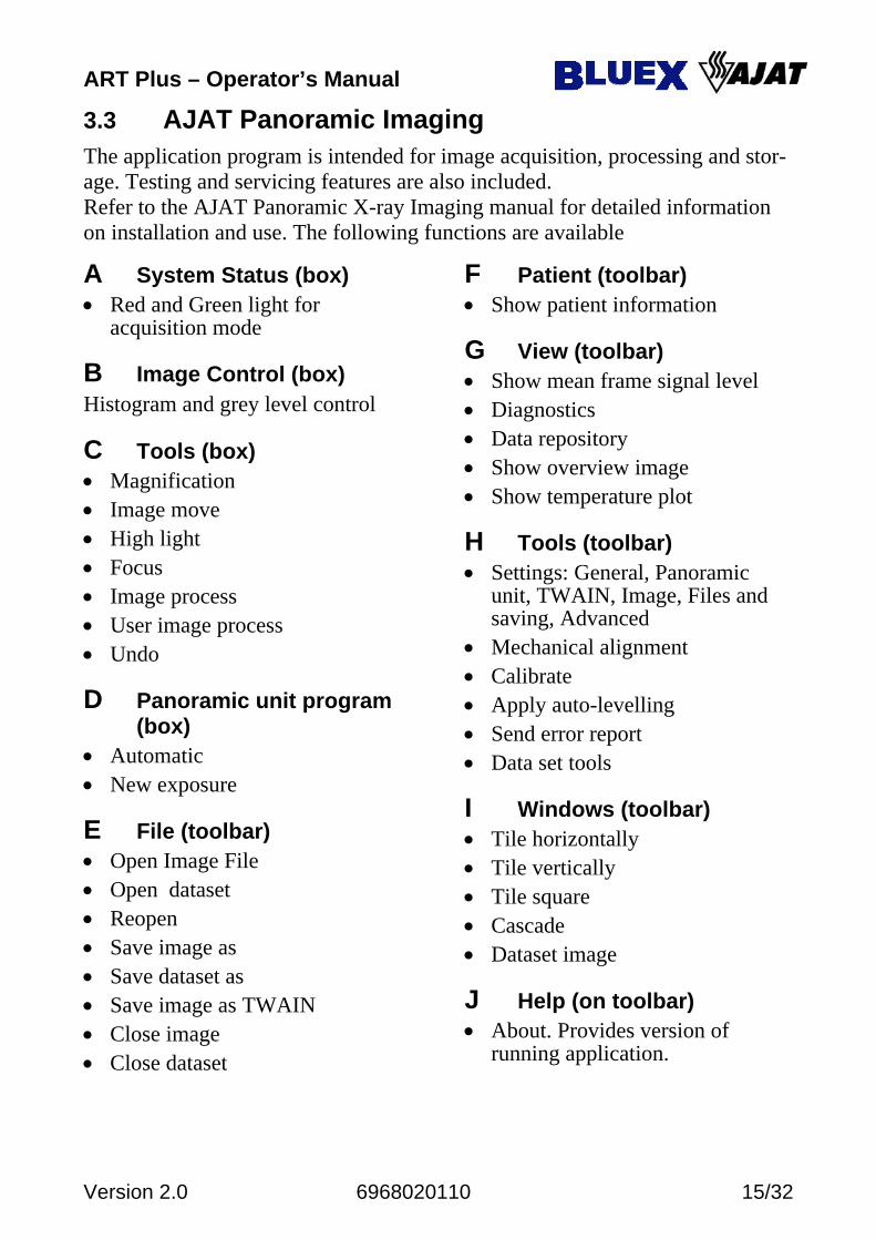
3.3 AJAT Panoramic Imaging The application program is intended for image acquisition, processing and stor-age. Testing and servicing features are also included. Refer to the AJAT Panoramic X-ray Imaging manual for detailed information on installation and use. The following functions are available
A System Status (box) • Red and Green light for
acquisition mode
B Image Control (box) Histogram and grey level control
C Tools (box) • Magnification • Image move • High light • Focus • Image process • User image process • Undo
D Panoramic unit program (box)
• Automatic • New exposure
E File (toolbar) • Open Image File • Open dataset • Reopen • Save image as • Save dataset as • Save image as TWAIN • Close image • Close dataset
F Patient (toolbar) • Show patient information
G View (toolbar) • Show mean frame signal level • Diagnostics • Data repository • Show overview image • Show temperature plot
H Tools (toolbar) • Settings: General, Panoramic
unit, TWAIN, Image, Files and saving, Advanced
• Mechanical alignment • Calibrate • Apply auto-levelling • Send error report • Data set tools
I Windows (toolbar) • Tile horizontally • Tile vertically • Tile square • Cascade • Dataset image
J Help (on toolbar) • About. Provides version of
running application.
ART Plus – Operator’s Manual
16/32 6968020110 Version 2.0
4. PANORAMIC RADIOLOGY
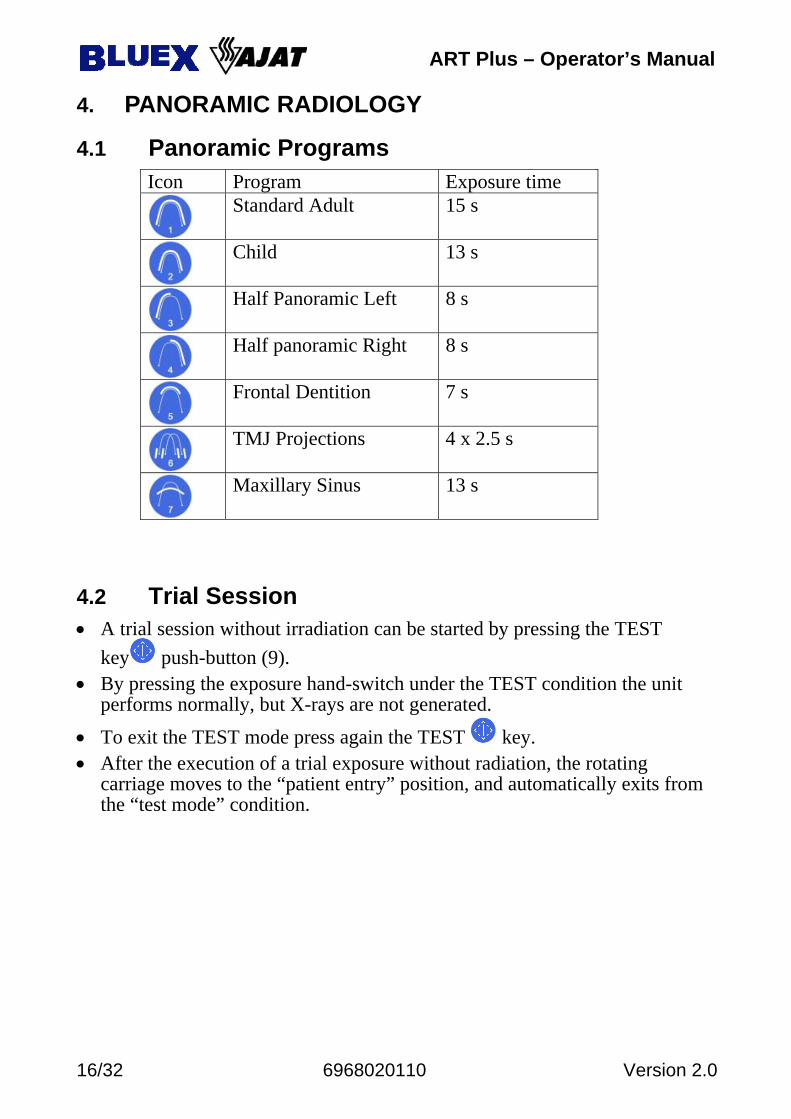
4.1 Panoramic Programs Icon Program Exposure time
Standard Adult 15 s
Child 13 s
Half Panoramic Left 8 s
Half panoramic Right 8 s
Frontal Dentition 7 s
TMJ Projections 4 x 2.5 s
Maxillary Sinus 13 s
4.2 Trial Session • A trial session without irradiation can be started by pressing the TEST
key push-button (9). • By pressing the exposure hand-switch under the TEST condition the unit
performs normally, but X-rays are not generated.
• To exit the TEST mode press again the TEST key. • After the execution of a trial exposure without radiation, the rotating
carriage moves to the “patient entry” position, and automatically exits from the “test mode” condition.
ART Plus – Operator’s Manual
Version 2.0 6968020110 17/32
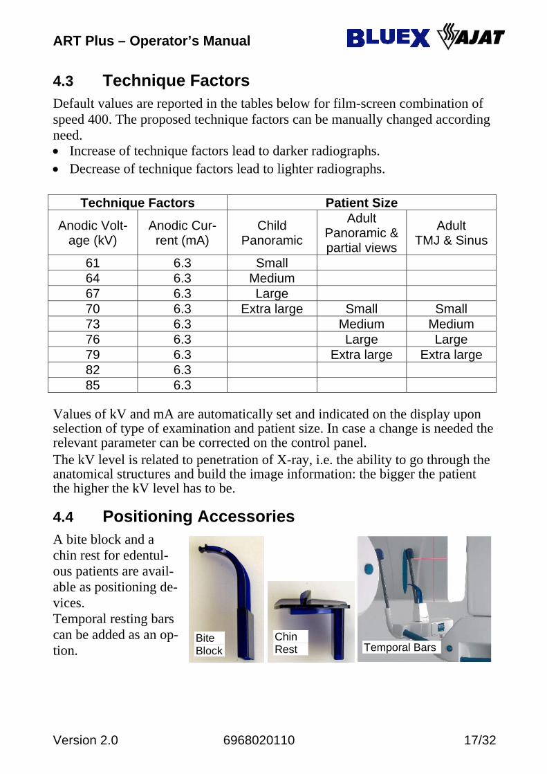
4.3 Technique Factors Default values are reported in the tables below for film-screen combination of speed 400. The proposed technique factors can be manually changed according need. • Increase of technique factors lead to darker radiographs. • Decrease of technique factors lead to lighter radiographs.
Technique Factors Patient Size
Anodic Volt-age (kV)
Anodic Cur-rent (mA)
Child Panoramic
Adult Panoramic & partial views
Adult TMJ & Sinus
61 6.3 Small 64 6.3 Medium 67 6.3 Large 70 6.3 Extra large Small Small 73 6.3 Medium Medium 76 6.3 Large Large 79 6.3 Extra large Extra large 82 6.3 85 6.3
Values of kV and mA are automatically set and indicated on the display upon selection of type of examination and patient size. In case a change is needed the relevant parameter can be corrected on the control panel. The kV level is related to penetration of X-ray, i.e. the ability to go through the anatomical structures and build the image information: the bigger the patient the higher the kV level has to be.
4.4 Positioning Accessories A bite block and a chin rest for edentul-ous patients are avail-able as positioning de-vices. Temporal resting bars can be added as an op-tion.
Chin Rest
Bite Block Temporal Bars

ART Plus – Operator’s Manual
18/32 6968020110 Version 2.0
4.5 The Aiming Lights The unit is equipped with a set of LASER lights for the three alignment planes: • Median Sagittal. It
divides the head of the patient in left and right side. Check to be done for the light beam to fall in the middle of the face.
• Frankfurt Horizontal Plane. This beam source can be moved up and down to align just above the ear hole and allow the operator to check for correct orientation of the head (forward or backward tilting of the head).
• Lateral Vertical Plane. It defines the center of the focal trough for the frontal teeth (incisors), i.e. the correct position of the carriage (backward or forward displacement of the rotating carriage) to have the teeth structures falling into the focal trough.
The laser light beams are activated with ALIGNMENT LIGHTS key on the control panel and stay on for 15 s. The laser aiming system is a Class I laser product. Avoid during patient positioning unnecessary exposure of the eyes of the patient or of the operator to the laser radiation. Also pay attention that the laser beams are not intercepted by any optical device.
4.6 Resetting Carriage in Patient Entry Position • The carriage is in PATIENT ENTRY position when the tube housing
assembly is on the right. The laser lights can be switched on and the alignment of patient performed. In case of different position:
push briefly the X-ray pushbutton or the ARM MOVEMENT key on the control panel to rotate forward
keep pressed briefly the RETURN key until it starts for backward rotation, from the READY position to PATIENT ENTRY position.
ART Plus – Operator’s Manual
Version 2.0 6968020110 19/32
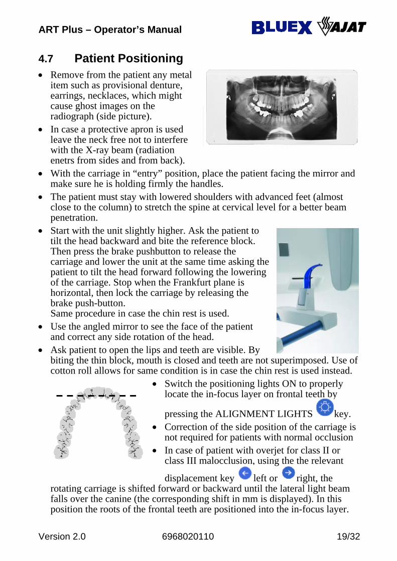
4.7 Patient Positioning • Remove from the patient any metal
item such as provisional denture, earrings, necklaces, which might cause ghost images on the radiograph (side picture).
• In case a protective apron is used leave the neck free not to interfere with the X-ray beam (radiation enetrs from sides and from back).
• With the carriage in “entry” position, place the patient facing the mirror and make sure he is holding firmly the handles.
• The patient must stay with lowered shoulders with advanced feet (almost close to the column) to stretch the spine at cervical level for a better beam penetration.
• Start with the unit slightly higher. Ask the patient to tilt the head backward and bite the reference block. Then press the brake pushbutton to release the carriage and lower the unit at the same time asking the patient to tilt the head forward following the lowering of the carriage. Stop when the Frankfurt plane is horizontal, then lock the carriage by releasing the brake push-button. Same procedure in case the chin rest is used.
• Use the angled mirror to see the face of the patient and correct any side rotation of the head.
• Ask patient to open the lips and teeth are visible. By biting the thin block, mouth is closed and teeth are not superimposed. Use of cotton roll allows for same condition is in case the chin rest is used instead.
• Switch the positioning lights ON to properly locate the in-focus layer on frontal teeth by
pressing the ALIGNMENT LIGHTS key. • Correction of the side position of the carriage is
not required for patients with normal occlusion • In case of patient with overjet for class II or
class III malocclusion, using the the relevant
displacement key left or right, the rotating carriage is shifted forward or backward until the lateral light beam falls over the canine (the corresponding shift in mm is displayed). In this position the roots of the frontal teeth are positioned into the in-focus layer.
ART Plus – Operator’s Manual
20/32 6968020110 Version 2.0
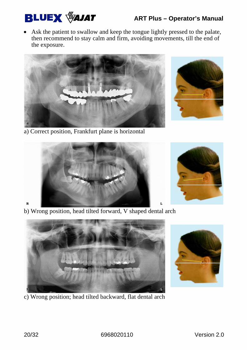
• Ask the patient to swallow and keep the tongue lightly pressed to the palate, then recommend to stay calm and firm, avoiding movements, till the end of the exposure.
a) Correct position, Frankfurt plane is horizontal
b) Wrong position, head tilted forward, V shaped dental arch
c) Wrong position; head tilted backward, flat dental arch
ART Plus – Operator’s Manual
Version 2.0 6968020110 21/32
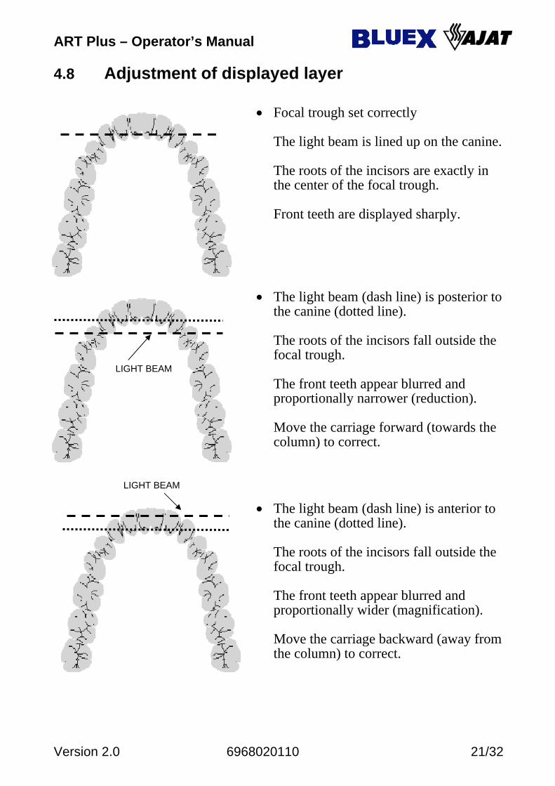
4.8 Adjustment of displayed layer • Focal trough set correctly
The light beam is lined up on the canine. The roots of the incisors are exactly in the center of the focal trough. Front teeth are displayed sharply.
• The light beam (dash line) is posterior to
the canine (dotted line). The roots of the incisors fall outside the focal trough. The front teeth appear blurred and proportionally narrower (reduction). Move the carriage forward (towards the column) to correct.
• The light beam (dash line) is anterior to
the canine (dotted line). The roots of the incisors fall outside the focal trough. The front teeth appear blurred and proportionally wider (magnification). Move the carriage backward (away from the column) to correct.
LIGHT BEAM
LIGHT BEAM
ART Plus – Operator’s Manual
22/32 6968020110 Version 2.0
1 2 3 4
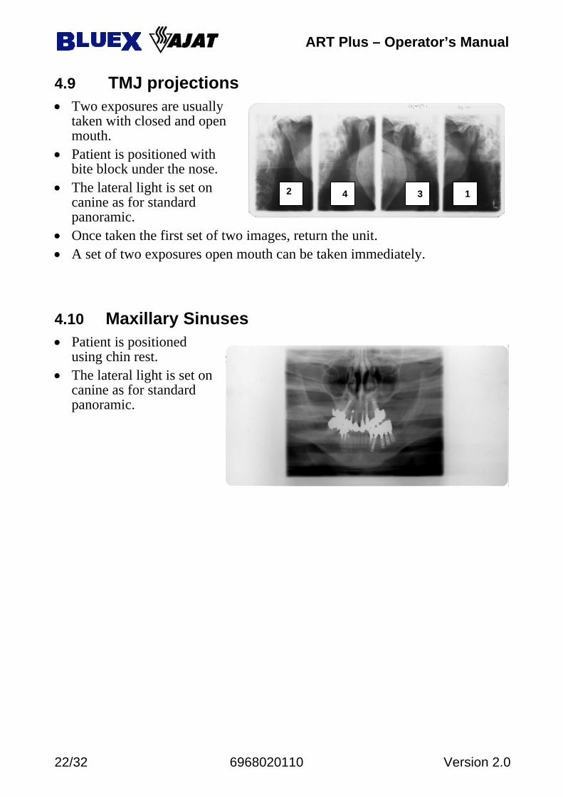
4.9 TMJ projections • Two exposures are usually
taken with closed and open mouth.
• Patient is positioned with bite block under the nose.
• The lateral light is set on canine as for standard panoramic.
• Once taken the first set of two images, return the unit. • A set of two exposures open mouth can be taken immediately.
4.10 Maxillary Sinuses • Patient is positioned
using chin rest. • The lateral light is set on
canine as for standard panoramic.
ART Plus – Operator’s Manual
Version 2.0 6968020110 23/32
4.11 Panoramic Exposure • Activate on computer the AJAT Panoramic Imaging application and make
sure the Green Light on System Status Box is turned ON.
• The READY light on the control panel has to be ON too. • The operator is invited to stay behind the patient, three meters from the
column, always keeping an eye to the patient, ready to terminate the exposure in case of need, at any time.
• Press the exposure hand-switch and hold it down during the whole cycle until the acoustical and optical alarms are terminated and the rotating carriage and the cassette holder stop.
• Press the hand switch or the ARM MOVEMENT key. The rotating unit performs the first part of return function to make it easier for the patient to exit.
• Press the hand switch or the ARM MOVEMENT key to return to the initial position for patient entry. Last used data are stored and appear on the display: Program number, patient size, carriage shift, used collimator, kV level, mA value.
• Press the hand switch to have the rotating arm moving to the START position. In case the patient is not properly positioned, the rotating arm can be brough to the PATIENT ENTRY position by pressing for few second the ALARM RESET key.
• Error messages to be handled by the operator: 11 - Exposure Aborted During Irradiation. 12 - Exposure Aborted Before Irradiation. 20 - Exposure aborted after irradiation. 29 - Data Acquisition System Not Ready. The AJAT Panoramic Imaging
program on computer has to be started first to make sure data acquisition will be performed during radiographic exposure.
ART Plus – Operator’s Manual
24/32 6968020110 Version 2.0
5. MAINTENANCE
5.1 Cleaning Switch the equipment off and possibly disconnect it from mains (room switch) before cleaning or disinfecting the unit. Use a mild soap to remove finger or other dirty marks paying attention not to have liquid substances enter into the equipment. Plastic covers can be wiped with a soft cloth and light detergent.
5.2 Disinfecting Parts which can come in touch with the patient must be cleaned with a deter-gent (such as 2% solution of ammonia) and then disinfected making sure sol-vents or corrosive disinfectants are NOT used. The bite block can be sterilized at 121°C.
5.3 Servicing It is the responsibility of the User to maintain the equipment in compliance with the standard. Failure of the User to properly maintain the equipment may relieve the Manufacturer, or its Agent, from responsibility for any injury, dam-age or non compliance which may result. Any defect or malfunction should be corrected immediately by qualified per-sonnel with adequate training. To be performed regularly: • Cleaning and disinfecting of the parts in touch of the patient. • Checking the condition of the cables for the vertical movement of the
carriage. If even only one wire of the strands of the steel rope is broken, the steel rope must be replaced immediately.
WARNING. Any defective item affecting a safe use must be re-paired or replaced. Maintenance to the equipment must be per-formed at least once a year by qualified personnel. The following actions to be done: • Complete check of system performance (kV, mA, mAs, s) • Check for proper working condition of all mechanical and electrical safety
features. • Lubrication of accessible parts. Specific lubrication of movable parts has to
be done by Technical Service at least every two years.
ART Plus – Operator’s Manual
Version 2.0 6968020110 25/32
5.4 Disposing of Obsolete Equipment A radiological system is made of different materials which include many kinds of metals (iron, aluminum, lead, copper and others), plastic mate-rials, electronic components and dielectric oil in the tank of the X-ray tube. The "crossed-out wheeled bin" symbol on the product indicates that the product at the end of its useful life must not be disposed of as unsorted municipal waste but has to be collected separately and delivered to specialized operators for re-cycling or disposal of waste of electrical and electronic equipment (WAEE), in compliance with existing laws. By doing in this way possible negative effects on human health and environ-ment are prevented, and recycling of the component materials is promoted. Pe-nalties are applicable to illicit disposal. Oy AJAT Ltd and its local Dealers commit to fulfill obligations related to the management of WAEE of professional nature, according to the provisions of the European directives 2002/96/EC and 2003/108/EC. 6. CLASSIFICATION • IEC: ART Plus is a Class I, type B equipment • IEC: ART Plus includes Class I lasers as aiming lights for patient
positioning (IEC 60825-1). ART Plus complies with the following standards. IEC 601-1 General requirements for safety IEC 601-1-2 Electromagnetic compatibility IEC 601-1-3 General requirements for radiation protection in diagnostic
X-ray equipment IEC 601-2-7 Particular requirements for the safety of high voltage genera-
tors of diagnostic X-ray generators IEC 601-2-28 Particular requirements for the safety of X-ray source as-
semblies and X-ray tube assemblies for medical diagnosis 21CFR1020.30 Performance Standards for Ionizing Radiation Emitting
Products: Diagnostic X-ray Systems and their major Compo-nents
21CFR1020.31 Performance Standards for Ionizing Radiation Emitting Products: Radiographic Equipment
21CFR1040.10 Performance Standard for Light Emitting Products: Laser products
IEC 60825-1 Safety of laser products. Part 1: Equipment classification, requirements and user’s guide
ART Plus – Operator’s Manual
26/32 6968020110 Version 2.0
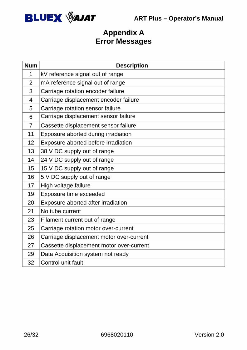
Appendix A Error Messages
Num Description
1 kV reference signal out of range 2 mA reference signal out of range 3 Carriage rotation encoder failure 4 Carriage displacement encoder failure 5 Carriage rotation sensor failure 6 Carriage displacement sensor failure 7 Cassette displacement sensor failure
11 Exposure aborted during irradiation 12 Exposure aborted before irradiation 13 38 V DC supply out of range 14 24 V DC supply out of range 15 15 V DC supply out of range 16 5 V DC supply out of range 17 High voltage failure 19 Exposure time exceeded 20 Exposure aborted after irradiation 21 No tube current 23 Filament current out of range 25 Carriage rotation motor over-current 26 Carriage displacement motor over-current 27 Cassette displacement motor over-current 29 Data Acquisition system not ready 32 Control unit fault
ART Plus – Operator’s Manual
Version 2.0 6968020110 27/32
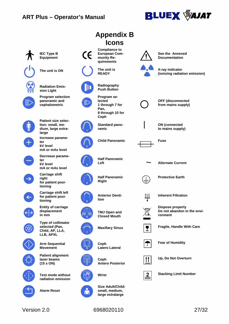
Appendix B Icons
IEC Type B Equipment
Compliance to European Com-munity Re-quirements
See the Annexed Documentation
The unit is ON
The unit is READY
X-ray indicator (ionizing radiation emission)
Radiation Emis-sion Light
Radiography Push Button
Program selectionpanoramic and cephalometric
Program se-lected 1 through 7 for Pan, 8 through 10 for Ceph
OFF (disconnected from mains supply)
Patient size selec-tion: small, me-dium, large extra-large
Standard pano-ramic
ON (connected to mains supply)
Increase parame-ter kV level mA or mAs level
Child Panoramic
Fuse
Decrease parame-ter kV level mA or mAs level
Half Panoramic Left
~ Alternate Current
Carriage shift right for patient posi-tioning
Half Panoramic Right
Protective Earth
Carriage shift left for patient posi-tioning
Anterior Denti-tion
Inherent Filtration
Entity of carriage displacement in mm
TMJ Open and Closed Mouth
Dispose properly Do not abandon in the envi-ronment
Type of collimator selected (Pan, Child, AP, LLA, LLB, APXL
Maxillary Sinus
Fragile, Handle With Care
Arm Sequential Movement
Ceph Latero Lateral
Fear of Humidity
Patient alignment laser beams (15 s ON)
Ceph Antero Posterior
Up, Do Not Overturn
Test mode without radiation emission
Wrist
Stacking Limit Number
Alarm Reset
Size Adult/Child:small, medium, large extralarge
ART Plus – Operator’s Manual
28/32 6968020110 Version 2.0
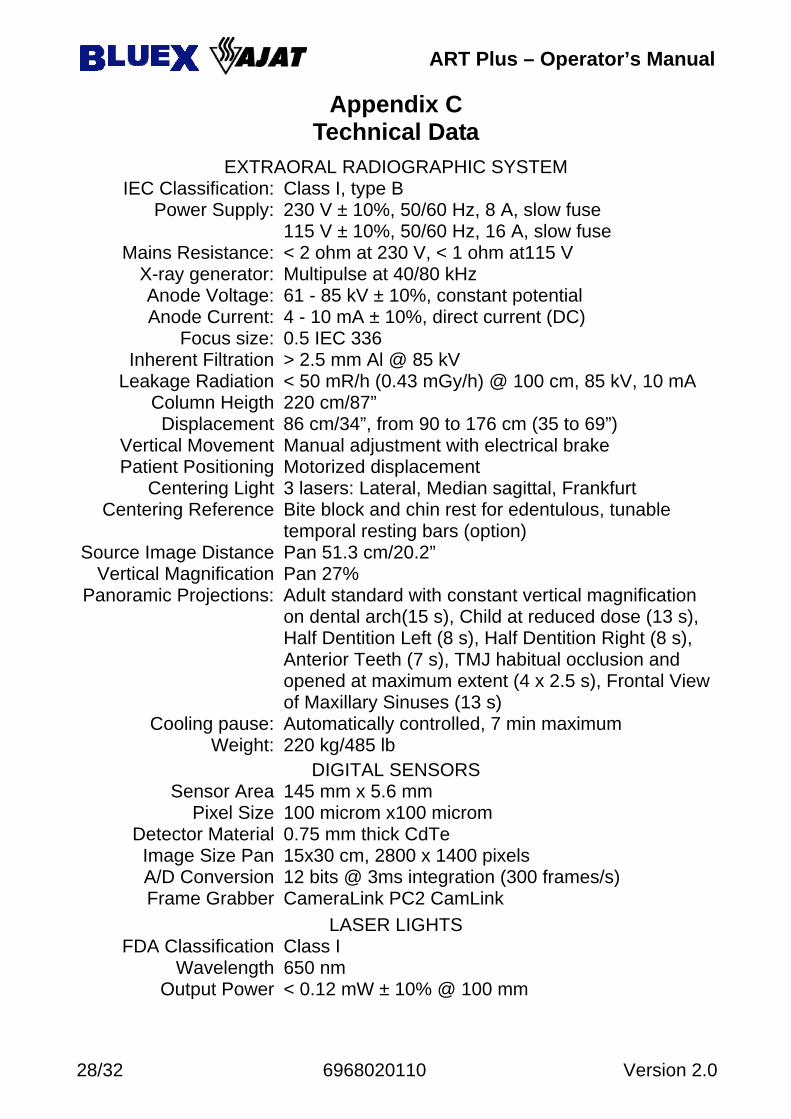
Appendix C Technical Data
EXTRAORAL RADIOGRAPHIC SYSTEM IEC Classification: Class I, type B
Power Supply: 230 V ± 10%, 50/60 Hz, 8 A, slow fuse 115 V ± 10%, 50/60 Hz, 16 A, slow fuse
Mains Resistance: < 2 ohm at 230 V, < 1 ohm at115 V X-ray generator: Multipulse at 40/80 kHz Anode Voltage: 61 - 85 kV ± 10%, constant potential Anode Current: 4 - 10 mA ± 10%, direct current (DC)
Focus size: 0.5 IEC 336 Inherent Filtration > 2.5 mm Al @ 85 kV
Leakage Radiation < 50 mR/h (0.43 mGy/h) @ 100 cm, 85 kV, 10 mA Column Heigth 220 cm/87” Displacement 86 cm/34”, from 90 to 176 cm (35 to 69”)
Vertical Movement Manual adjustment with electrical brake Patient Positioning Motorized displacement
Centering Light 3 lasers: Lateral, Median sagittal, Frankfurt Centering Reference Bite block and chin rest for edentulous, tunable
temporal resting bars (option) Source Image Distance Pan 51.3 cm/20.2”
Vertical Magnification Pan 27% Panoramic Projections: Adult standard with constant vertical magnification
on dental arch(15 s), Child at reduced dose (13 s), Half Dentition Left (8 s), Half Dentition Right (8 s), Anterior Teeth (7 s), TMJ habitual occlusion and opened at maximum extent (4 x 2.5 s), Frontal View of Maxillary Sinuses (13 s)
Cooling pause: Automatically controlled, 7 min maximum Weight: 220 kg/485 lb
DIGITAL SENSORS Sensor Area 145 mm x 5.6 mm
Pixel Size 100 microm x100 microm Detector Material 0.75 mm thick CdTe
Image Size Pan 15x30 cm, 2800 x 1400 pixels A/D Conversion 12 bits @ 3ms integration (300 frames/s) Frame Grabber CameraLink PC2 CamLink
LASER LIGHTS FDA Classification Class I
Wavelength 650 nm Output Power < 0.12 mW ± 10% @ 100 mm
ART Plus – Operator’s Manual
Version 2.0 6968020110 29/32
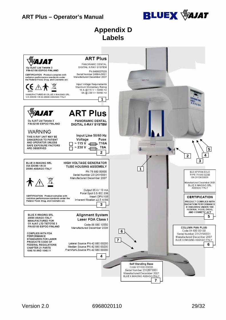
Appendix D Labels
1
43
5
6
2
7
4
3
2
7
6
5
1
ART Plus – Operator’s Manual
30/32 6968020110 Version 2.0
0
20
40
60
80
100
120
0 15 30 45 60 75 90 105 120 135 150 165 180
0
2
4
6
8
10
12
14
16
18
20
0 1 2 3 4 5 6
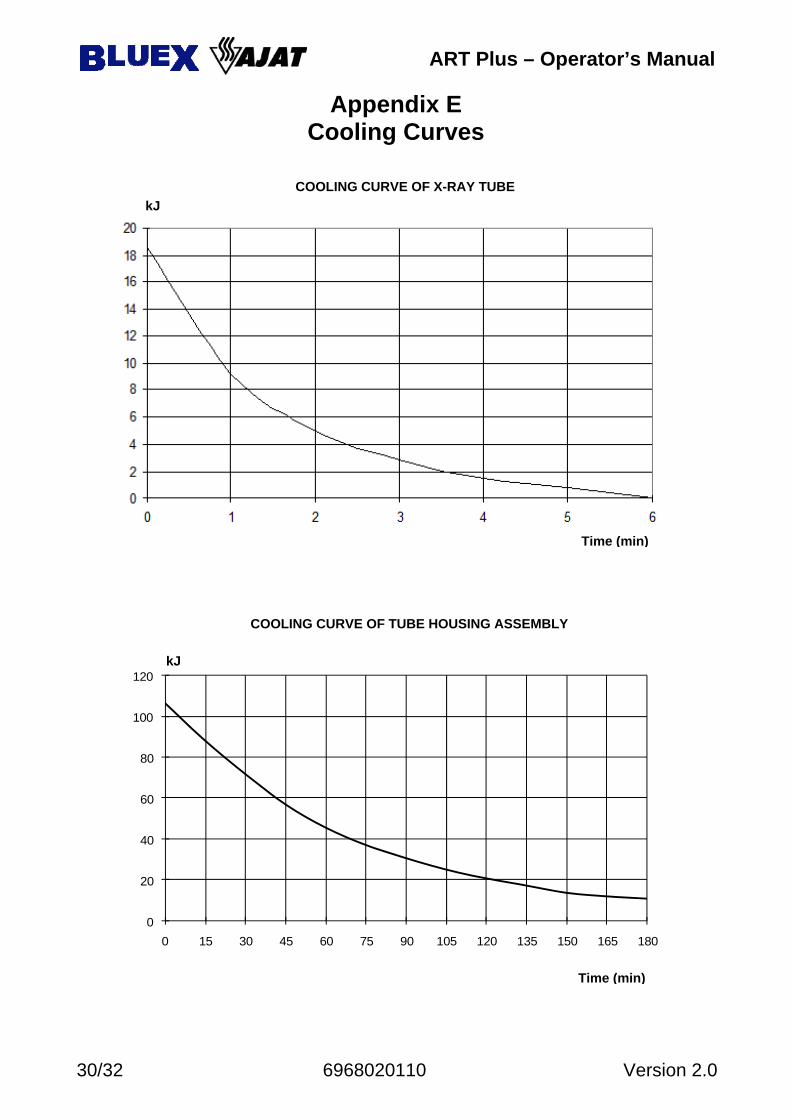
Appendix E Cooling Curves
COOLING CURVE OF X-RAY TUBE
Time (min)
kJ
COOLING CURVE OF TUBE HOUSING ASSEMBLY
kJ
Time (min)
ART Plus – Operator’s Manual
Version 2.0 6968020110 31/32
FU 304 FU 305
CONFIGURATION CONNECTOR PLUG
FU 303
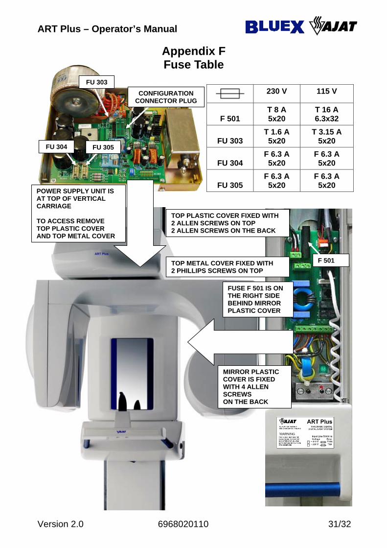
Appendix F Fuse Table
230 V 115 V
F 501
T 8 A 5x20
T 16 A 6.3x32
FU 303
T 1.6 A 5x20
T 3.15 A 5x20
FU 304
F 6.3 A 5x20
F 6.3 A 5x20
FU 305
F 6.3 A 5x20
F 6.3 A 5x20
POWER SUPPLY UNIT IS AT TOP OF VERTICAL CARRIAGE TO ACCESS REMOVE TOP PLASTIC COVER AND TOP METAL COVER
TOP METAL COVER FIXED WITH 2 PHILLIPS SCREWS ON TOP
TOP PLASTIC COVER FIXED WITH 2 ALLEN SCREWS ON TOP 2 ALLEN SCREWS ON THE BACK
FUSE F 501 IS ON THE RIGHT SIDE BEHIND MIRROR PLASTIC COVER
MIRROR PLASTIC COVER IS FIXED WITH 4 ALLEN SCREWS ON THE BACK
F 501
ART Plus Dental Panoramic X-Ray
Operator’s Manual English Edition
Version 2.0
*6968020110*