690A-0999 M1 Series sm - Nortek Global HVACenora.nortekhvac.com/literature/690a.pdf · Furnace...
36
M1 Series Service Manual M1G and M1M Furnaces
-
Upload
nguyenthuan -
Category
Documents
-
view
222 -
download
2
Transcript of 690A-0999 M1 Series sm - Nortek Global HVACenora.nortekhvac.com/literature/690a.pdf · Furnace...
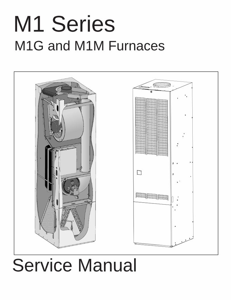
M1 Series
Service Manual
M1G and M1M Furnaces
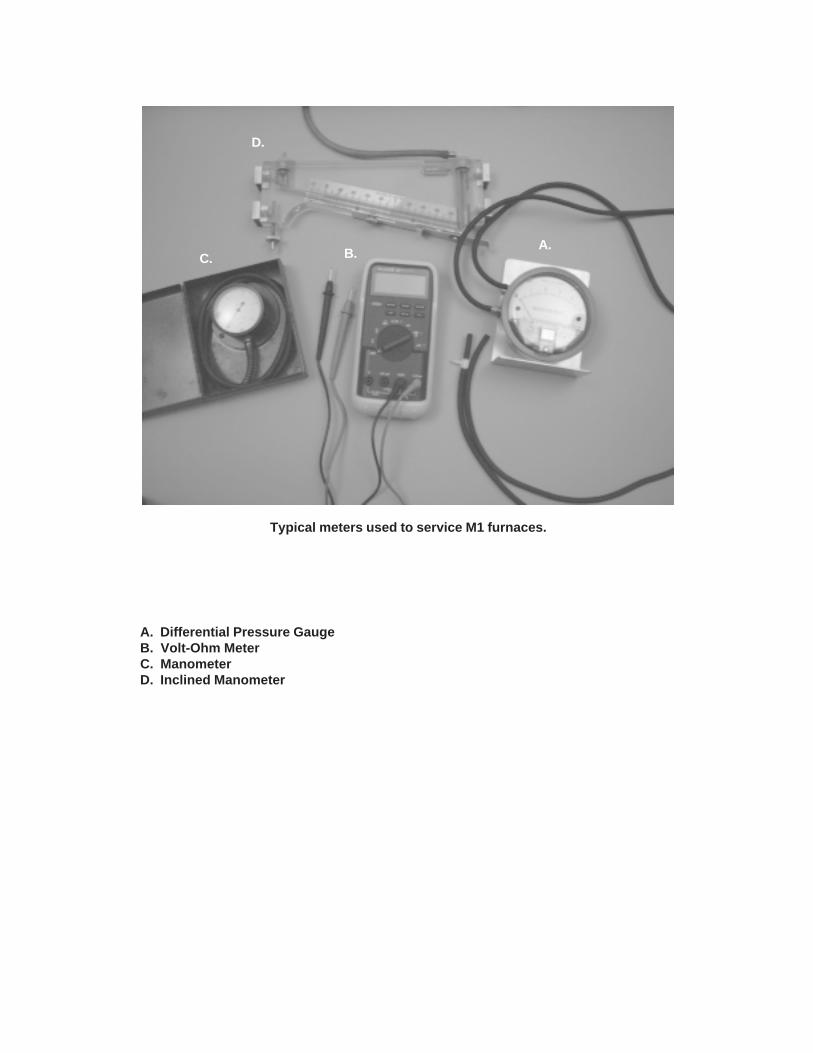
Typical meters used to service M1 furnaces.
A. Differential Pressure GaugeB. Volt-Ohm MeterC. ManometerD. Inclined Manometer
A.B.C.
D.
3
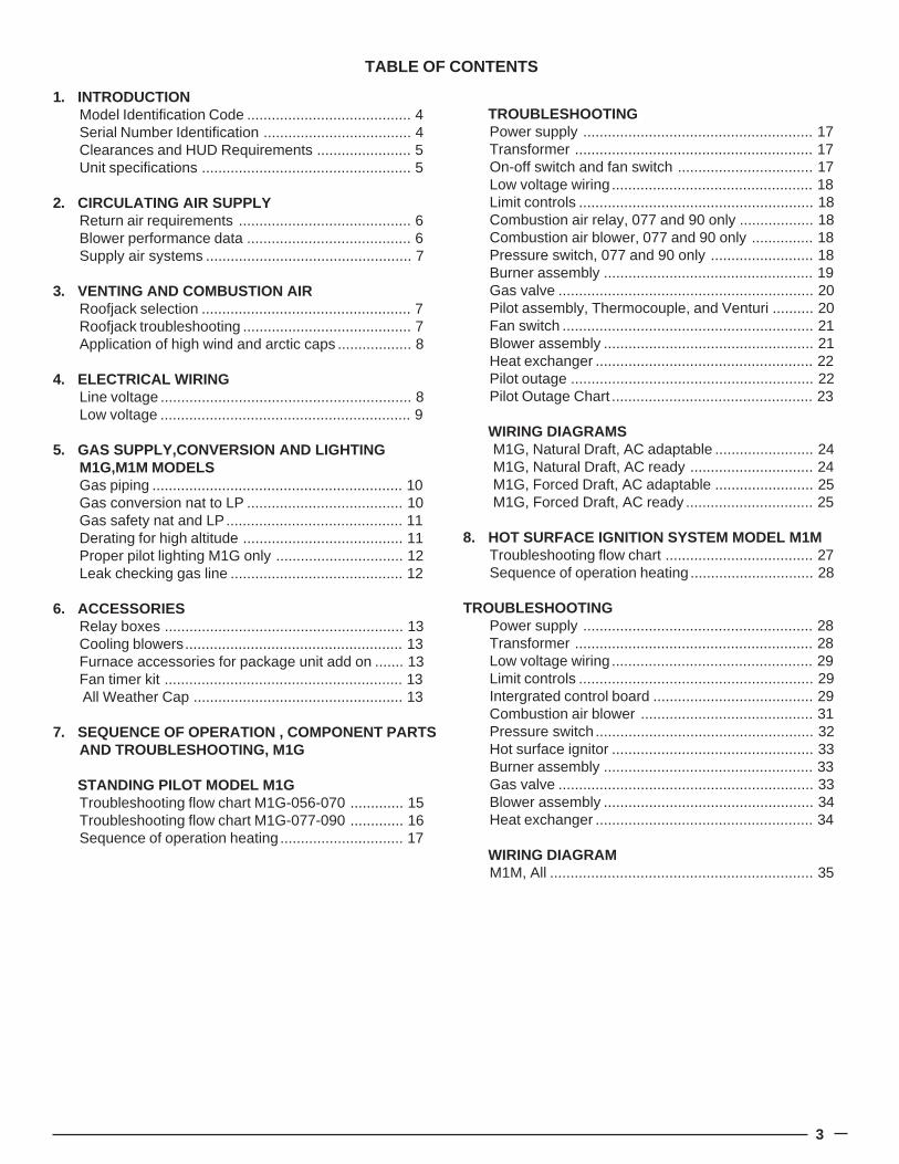
TABLE OF CONTENTS
1. INTRODUCTIONModel Identification Code ........................................ 4Serial Number Identification .................................... 4Clearances and HUD Requirements ....................... 5Unit specifications ................................................... 5
2. CIRCULATING AIR SUPPLYReturn air requirements .......................................... 6Blower performance data ........................................ 6Supply air systems .................................................. 7
3. VENTING AND COMBUSTION AIRRoofjack selection ................................................... 7Roofjack troubleshooting ......................................... 7Application of high wind and arctic caps .................. 8
4. ELECTRICAL WIRINGLine voltage ............................................................. 8Low voltage ............................................................. 9
5. GAS SUPPLY,CONVERSION AND LIGHTINGM1G,M1M MODELSGas piping ............................................................. 10Gas conversion nat to LP ...................................... 10Gas safety nat and LP........................................... 11Derating for high altitude ....................................... 11Proper pilot lighting M1G only ............................... 12Leak checking gas line .......................................... 12
6. ACCESSORIESRelay boxes .......................................................... 13Cooling blowers..................................................... 13Furnace accessories for package unit add on ....... 13Fan timer kit .......................................................... 13All Weather Cap ................................................... 13
7. SEQUENCE OF OPERATION , COMPONENT PARTSAND TROUBLESHOOTING, M1G
STANDING PILOT MODEL M1GTroubleshooting flow chart M1G-056-070 ............. 15Troubleshooting flow chart M1G-077-090 ............. 16Sequence of operation heating .............................. 17
TROUBLESHOOTINGPower supply ........................................................ 17Transformer .......................................................... 17On-off switch and fan switch ................................. 17Low voltage wiring ................................................. 18Limit controls ......................................................... 18Combustion air relay, 077 and 90 only .................. 18Combustion air blower, 077 and 90 only ............... 18Pressure switch, 077 and 90 only ......................... 18Burner assembly ................................................... 19Gas valve .............................................................. 20Pilot assembly, Thermocouple, and Venturi .......... 20Fan switch ............................................................. 21Blower assembly ................................................... 21Heat exchanger ..................................................... 22Pilot outage ........................................................... 22Pilot Outage Chart ................................................. 23
WIRING DIAGRAMSM1G, Natural Draft, AC adaptable ........................ 24M1G, Natural Draft, AC ready .............................. 24M1G, Forced Draft, AC adaptable ........................ 25M1G, Forced Draft, AC ready ............................... 25
8. HOT SURFACE IGNITION SYSTEM MODEL M1MTroubleshooting flow chart .................................... 27Sequence of operation heating .............................. 28
TROUBLESHOOTINGPower supply ........................................................ 28Transformer .......................................................... 28Low voltage wiring ................................................. 29Limit controls ......................................................... 29Intergrated control board ....................................... 29Combustion air blower .......................................... 31Pressure switch ..................................................... 32Hot surface ignitor ................................................. 33Burner assembly ................................................... 33Gas valve .............................................................. 33Blower assembly ................................................... 34Heat exchanger ..................................................... 34
WIRING DIAGRAMM1M, All ................................................................ 35
4
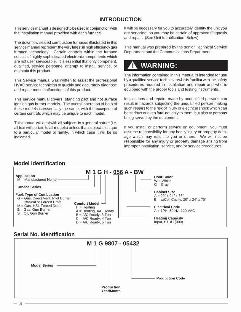
Model Identification
Door ColorW = WhiteG = Gray
Cabinet SizeA = 20" x 24" x 56”B = w/Coil Cavity, 20” x 24” x 76”
Electrical CodeA = 1PH, 60 Hz, 120 VAC
Heating CapacityInput, BTUH (000)
ApplicationM = Manufactured Home
Furnace Series
Fuel, Type of CombustionG = Gas, Direct Vent, Pilot Burner Natural or Forced DraftM = Gas, HSI, Forced DraftB = Gas, Gun BurnerS = Oil, Gun Burner
M 1 G H - 056 A - BW
Comfort ModelH = HeatingA = Heating, A/C ReadyB = A/C Ready, 3 TonC = A/C Ready, 4 TonD = A/C Ready, 5 Ton
INTRODUCTION
This service manual is designed to be used in conjunction withthe installation manual provided with each furnace.
The downflow sealed combustion furnaces illustrated in thisservice manual represent the very latest in high efficiency gasfurnace technology. Certain controls within the furnaceconsist of highly sophisticated electronic components whichare not user serviceable. It is essential that only competent,qualified, service personnel attempt to install, service, ormaintain this product.
This Service manual was written to assist the professionalHVAC service technician to quickly and accurately diagnoseand repair most malfunctions of this product.
This service manual covers standing pilot and hot surfaceignition gas burner models. The overall operation of both ofthese models is essentially the same, with the exception ofcertain controls which may be unique to each model.
This manual will deal with all subjects in a general nature (i.e.all text will pertain to all models) unless that subject is uniqueto a particular model or family, in which case it will be soindicated.
It will be necessary for you to accurately identify the unit youare servicing, so you may be certain of approved diagnosisand repair. (See Unit Identification, Below)
This manual was prepared by the senior Technical ServiceDepartment and the Communications Department.
The information contained in this manual is intended for useby a qualified service technician who is familiar with the safetyprocedures required in installation and repair and who isequipped with the proper tools and testing instruments.
Installations and repairs made by unqualified persons canresult in hazards subjecting the unqualified person makingsuch repairs to the risk of injury or electrical shock which canbe serious or even fatal not only to them, but also to personsbeing served by the equipment.
If you install or perform service on equipment, you mustassume responsibility for any bodily injury or property dam-age which may result to you or others. We will not beresponsible for any injury or property damage arising fromimproper installation, service, and/or service procedures.
WARNING:!
Serial No. Identification
Model Series
M 1 G 9807 - 05432
ProductionYear/Month
Production Code
5
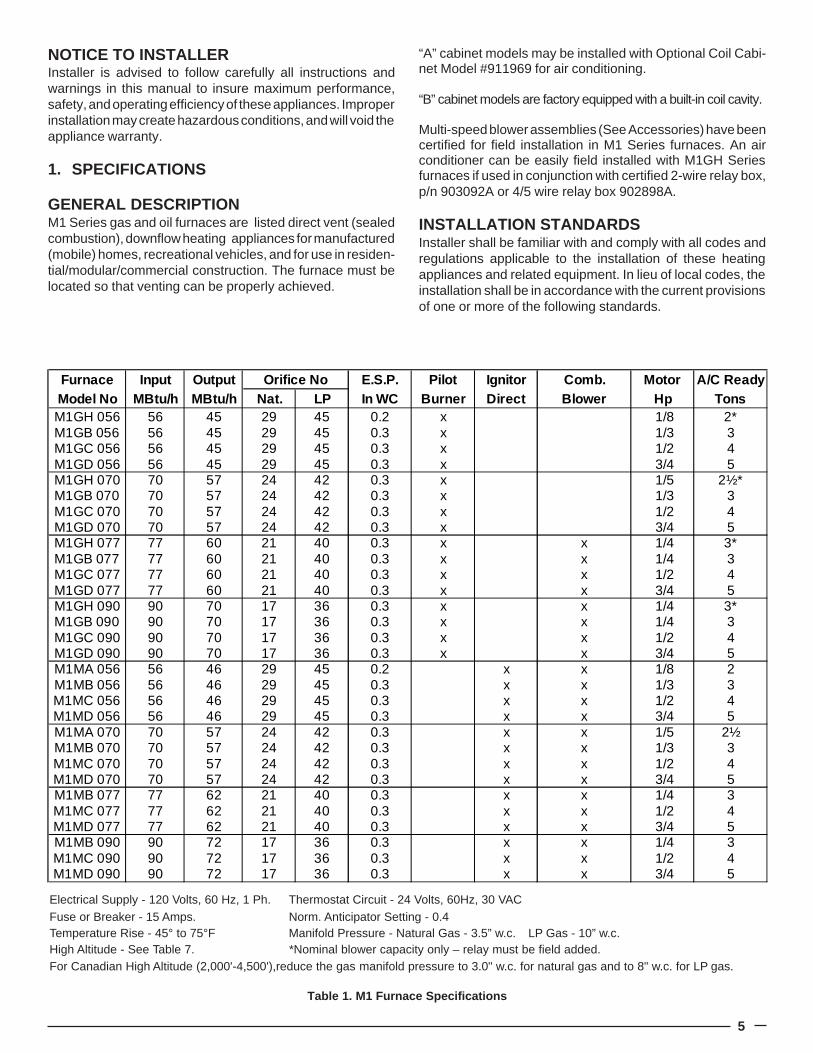
Table 1. M1 Furnace Specifications
NOTICE TO INSTALLERInstaller is advised to follow carefully all instructions andwarnings in this manual to insure maximum performance,safety, and operating efficiency of these appliances. Improperinstallation may create hazardous conditions, and will void theappliance warranty.
1. SPECIFICATIONS
GENERAL DESCRIPTIONM1 Series gas and oil furnaces are listed direct vent (sealedcombustion), downflow heating appliances for manufactured(mobile) homes, recreational vehicles, and for use in residen-tial/modular/commercial construction. The furnace must belocated so that venting can be properly achieved.
“A” cabinet models may be installed with Optional Coil Cabi-net Model #911969 for air conditioning.
“B” cabinet models are factory equipped with a built-in coil cavity.
Multi-speed blower assemblies (See Accessories) have beencertified for field installation in M1 Series furnaces. An airconditioner can be easily field installed with M1GH Seriesfurnaces if used in conjunction with certified 2-wire relay box,p/n 903092A or 4/5 wire relay box 902898A.
INSTALLATION STANDARDSInstaller shall be familiar with and comply with all codes andregulations applicable to the installation of these heatingappliances and related equipment. In lieu of local codes, theinstallation shall be in accordance with the current provisionsof one or more of the following standards.
Electrical Supply - 120 Volts, 60 Hz, 1 Ph. Thermostat Circuit - 24 Volts, 60Hz, 30 VACFuse or Breaker - 15 Amps. Norm. Anticipator Setting - 0.4Temperature Rise - 45° to 75°F Manifold Pressure - Natural Gas - 3.5” w.c. LP Gas - 10” w.c.High Altitude - See Table 7. *Nominal blower capacity only – relay must be field added.For Canadian High Altitude (2,000'-4,500'),reduce the gas manifold pressure to 3.0" w.c. for natural gas and to 8" w.c. for LP gas.
Furnace Input Output Orifice No E.S.P. Pilot Ignitor Comb. Motor A/C ReadyModel No MBtu/h MBtu/h Nat. LP In WC Burner Direct Blower Hp TonsM1GH 056 56 45 29 45 0.2 x 1/8 2*M1GB 056 56 45 29 45 0.3 x 1/3 3M1GC 056 56 45 29 45 0.3 x 1/2 4M1GD 056 56 45 29 45 0.3 x 3/4 5M1GH 070 70 57 24 42 0.3 x 1/5 2½*M1GB 070 70 57 24 42 0.3 x 1/3 3M1GC 070 70 57 24 42 0.3 x 1/2 4M1GD 070 70 57 24 42 0.3 x 3/4 5M1GH 077 77 60 21 40 0.3 x x 1/4 3*M1GB 077 77 60 21 40 0.3 x x 1/4 3M1GC 077 77 60 21 40 0.3 x x 1/2 4M1GD 077 77 60 21 40 0.3 x x 3/4 5M1GH 090 90 70 17 36 0.3 x x 1/4 3*M1GB 090 90 70 17 36 0.3 x x 1/4 3M1GC 090 90 70 17 36 0.3 x x 1/2 4M1GD 090 90 70 17 36 0.3 x x 3/4 5M1MA 056 56 46 29 45 0.2 x x 1/8 2M1MB 056 56 46 29 45 0.3 x x 1/3 3M1MC 056 56 46 29 45 0.3 x x 1/2 4M1MD 056 56 46 29 45 0.3 x x 3/4 5M1MA 070 70 57 24 42 0.3 x x 1/5 2½M1MB 070 70 57 24 42 0.3 x x 1/3 3M1MC 070 70 57 24 42 0.3 x x 1/2 4M1MD 070 70 57 24 42 0.3 x x 3/4 5M1MB 077 77 62 21 40 0.3 x x 1/4 3M1MC 077 77 62 21 40 0.3 x x 1/2 4M1MD 077 77 62 21 40 0.3 x x 3/4 5M1MB 090 90 72 17 36 0.3 x x 1/4 3M1MC 090 90 72 17 36 0.3 x x 1/2 4M1MD 090 90 72 17 36 0.3 x x 3/4 5
6
a. Federal Manufactured Home Constructions & SafetyStandard (H.U.D. Title 24, Part 3280.707[a][2])
b. American National Standard (ANSI-119.2/NFPA-501C)for all recreational vehicle installations.
c. American National Standard (ANSI-Z223.1/NFPA-54)and/or CAN/CGA B149 for all gas-fired furnace models.
d. American National Standard (ANSI-Z95.1/NFPA-31) and/or CSA B139 for all oil-fired furnace models.
e. American National Standard (ANSI-C1/NFPA-70) and/orCSA 22.1 Canadian Electric Code Part 1 for all electricalfield wiring.
f. Units have been investigated under standards UL 307A& B, ANZI 21.47a — CAN/2.3a - 1995, and CSA B140.10.
2. CIRCULATING AIR SUPPLY
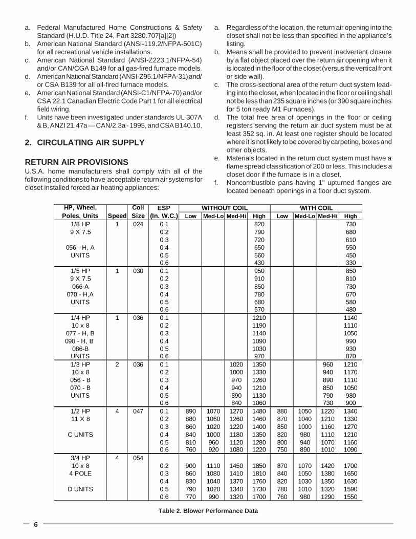
RETURN AIR PROVISIONSU.S.A. home manufacturers shall comply with all of thefollowing conditions to have acceptable return air systems forcloset installed forced air heating appliances:
a. Regardless of the location, the return air opening into thecloset shall not be less than specified in the appliance’slisting.
b. Means shall be provided to prevent inadvertent closureby a flat object placed over the return air opening when itis located in the floor of the closet (versus the vertical frontor side wall).
c. The cross-sectional area of the return duct system lead-ing into the closet, when located in the floor or ceiling shallnot be less than 235 square inches (or 390 square inchesfor 5 ton ready M1 Furnaces).
d. The total free area of openings in the floor or ceilingregisters serving the return air duct system must be atleast 352 sq. in. At least one register should be locatedwhere it is not likely to be covered by carpeting, boxes andother objects.
e. Materials located in the return duct system must have aflame spread classification of 200 or less. This includes acloset door if the furnace is in a closet.
f. Noncombustible pans having 1" upturned flanges arelocated beneath openings in a floor duct system.
Table 2. Blower Performance Data
ESP(In. W.C.) Low Med-Lo Med-Hi High Low Med-Lo Med-Hi High
1/8 HP 1 024 0.1 820 7309 X 7.5 0.2 790 680
0.3 720 610056 - H, A 0.4 650 550
UNITS 0.5 560 4500.6 430 330
1/5 HP 1 030 0.1 950 8509 X 7.5 0.2 910 810066-A 0.3 850 730
070 - H,A 0.4 780 670UNITS 0.5 680 580
0.6 570 4801/4 HP 1 036 0.1 1210 114010 x 8 0.2 1190 1110
077 - H, B 0.3 1140 1050090 - H, B 0.4 1090 990
086-B 0.5 1030 930UNITS 0.6 970 8701/3 HP 2 036 0.1 1020 1350 960 121010 x 8 0.2 1000 1330 940 1170056 - B 0.3 970 1260 890 1110070 - B 0.4 940 1210 850 1050UNITS 0.5 890 1130 790 980
0.6 840 1060 730 9001/2 HP 4 047 0.1 890 1070 1270 1480 880 1050 1220 134011 X 8 0.2 880 1060 1260 1460 870 1040 1210 1330
0.3 860 1020 1220 1400 850 1000 1160 1270C UNITS 0.4 840 1000 1180 1350 820 980 1110 1210
0.5 810 960 1120 1280 800 940 1070 11600.6 760 920 1080 1220 750 890 1010 1090
3/4 HP 4 05410 x 8 0.2 900 1110 1450 1850 870 1070 1420 1700
4 POLE 0.3 860 1080 1410 1810 840 1050 1380 16500.4 830 1040 1370 1760 820 1030 1350 1630
D UNITS 0.5 790 1020 1340 1730 780 1010 1320 15900.6 770 990 1320 1700 760 980 1290 1550
HP, Wheel, Poles, Units
Coil Size
WITHOUT COIL WITH COILSpeed
7
g. Wiring materials located in the return duct system shallconform to Articles 300-22 of the National ElectricalCode (ANSI C1/NFPA-70).
h. Gas piping is not run in or through the return duct system.i. Test the negative pressure in the closet with the air-
circulating fan operating at high speed and the closetclosed. The negative pressure is to be no more negativethan minus 0.05 inch water column.
j. For floor return systems, the manufactured home manu-facturer shall affix a prominent marking on or near theappliance where it can be easily read when the closetdoor is open. The marking shall read:
k. Air conditioning systems may require more duct, registerand open louver area to obtain necessary airflow. UseNORDYNE’s certiduct program to determine properduct size for A/C.
Air Distribution Systems
For proper air distribution, the supply duct system must bedesigned so that the static pressure measured external to thefurnace does not exceed the listed static pressure ratingshown on the furnace rating plate.
Before installing an air conditioner system, consult homemanufacturer for duct system maximum capacity. Location,size, and number of registers should be selected on the basisof best air distribution and floor plan of the home.
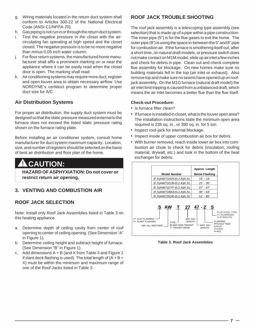
Table 3. Roof Jack Assemblies
CAUTION:HAZARD OF ASPHYXIATION: Do not cover orrestrict return air opening.
!
3. VENTING AND COMBUSTION AIR
ROOF JACK SELECTION
Note: Install only Roof Jack Assemblies listed in Table 3 onthis heating appliance.
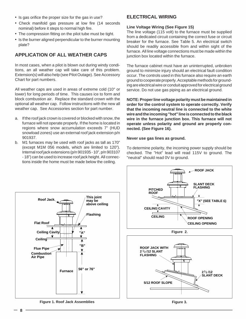
a. Determine depth of ceiling cavity from center of roofopening to center of ceiling opening. (See Dimension “A”in Figure 1).
b. Determine ceiling height and subtract height of furnace.(See Dimension “B” in Figure 1).
c. Add dimensions A + B (and X from Table 3 and Figure 2if slant deck flashing is used). The total length of (A + B +X) must be within the minimum and maximum range ofone of the Roof Jacks listed in Table 3.
ROOF JACK TROUBLE SHOOTING
The roof jack assembly is a telescoping type assembly (seeselection) that is made up of a pipe within a pipe construction.The inner pipe (5”) is for the flue gases to exit the home. Theouter pipe (8”) is using the space in-between the 5” and 8” pipefor combustion air. If the furnace is smothering itself out, aftera short time, on natural draft models, or pressure switch doesnot make contact on M1M model, slide up air inlet a few inchesand check for debris in pipe. Clean out and check completeflue assembly for blockage. On new homes make sure nobuilding materials fell in the top (air inlet or exhaust). Alsoremove top and make sure no seams have opened up on roof-jack assembly. On the M1G furnace (natural draft model) theair inlet limit tripping is caused from a unbalanced draft, whichmeans the air inlet becomes a better flue than the flue itself.
Check-out Procedure:� Is furnace filter clean?� If furnace is installed in closet, what is the louver open area?
The installation instructions state the minimum open arearequired is 235 sq. in., or 390 sq. in. for 5 ton.
� Inspect roof-jack for internal blockage.� Inspect inside of upper combustion air box for debris.� With burner removed, reach inside lower air box into com-
bustion air chute to check for debris (insulation, roofingmaterial, drywall, etc.) and look in the bottom of the heatexchanger for debris.
S SAW T 27 47 - 2
AW= ALL WEATHER
FLASHINGPITCH/12" RISE0=FLAT2=2.5/124=4/12
MIN. ADJ.LENGTH
F=S=
FLAT FLASHINGSLANT FLASHING TYPE:
BLANK=NON-TRANSITT= TRANSIT MODE
MAX. ADJ.LENGTH
FLUE STEEL TYPEA= ALUMINIZEDS=STAINLESS
Approx. Length
Model Number Below Flashing
(F,S)AW(T)1523-(0,2,4)(A,S) 15" - 23"
(F,S)AW(T)2135-(0,2,4)(A,S) 21" - 35"
(F,S)AW(T)2747-(0,2,4)(A,S) 27" - 47"
(F,S)AW(T)3563-(0,2,4)(A,S) 35" - 63"
(F,S)AW(T)5195-(0,2,4)(A,S) 51" - 95"
8
� Is gas orifice the proper size for the gas in use?� Check manifold gas pressure at low fire (14 seconds
nominal) before it steps to normal high fire.� The compression fitting on the pilot tube must be tight.� Is the burner aligned perpendicular to the burner mounting
plate?
APPLICATION OF ALL WEATHER CAPS
In most cases, when a pilot is blown out during windy condi-tions, an all weather cap will take care of this problem.Extension(s) will also help (see Pilot Outage). See AccessoryChart for part numbers.
All weather caps are used in areas of extreme cold (10° orlower) for long periods of time. This causes ice to form andblock combustion air. Replace the standard crown with theoptional all weather cap. Follow instructions with the new allweather cap. See Accessories section for part number.
a. If the roof jack crown is covered or blocked with snow, thefurnace will not operate properly. If the home is located inregions where snow accumulation exceeds 7” (HUDsnowload zones) use an external roof jack extension p/n901937.
b. M1 furnaces may be used with roof jacks as tall as 170”(except M1M 056 models, which are limited to 120”).Internal roof jack extensions (p/n 901935 - 10”, p/n 903107- 18”) can be used to increase roof jack height. All connec-tions inside the home must be made below the ceiling.
ELECTRICAL WIRING
Line Voltage Wiring (See Figure 15)The line voltage (115 volt) to the furnace must be suppliedfrom a dedicated circuit containing the correct fuse or circuitbreaker for the furnace. See Table 5. An electrical switchshould be readily accessible from and within sight of thefurnace. All line voltage connections must be made within thejunction box located within the furnace.
The furnace cabinet must have an uninterrupted, unbrokenground to minimize injury should an electrical fault conditionoccur. The controls used in this furnace also require an earthground to cooperate properly. Acceptable methods for ground-ing are electrical wire or conduit approved for electrical groundservice. Do not use gas piping as an electrical ground.
NOTE: Proper line voltage polarity must be maintained inorder for the control system to operate correctly. Verifythat the incoming neutral line is connected to the whitewire and the incoming "hot" line is connected to the blackwire in the furnace junction box. This furnace will notoperate unless polarity and ground are properly con-nected. (See Figure 16).
Never use gas lines as ground.
To determine polarity, the incoming power supply should bechecked. The "Hot" lead will read 115V to ground. The"neutral" should read 0V to ground.
Figure 2.
Figure 3.Figure 1. Roof Jack Assemblies
Roof Jack
Flat Roof
Ceiling Cavity
Ceiling
Flue PipeCombustionAir Pipe
Flashing
This jointmay beabove ceiling
"A"
"B"
56" or 76"Furnace
5/12 ROOF SLOPE
2SLANT DECK
/121 2
ROOF JACK WITH2FLASHING
/12 SLANT1 2
ROOF JACK
SLANT DECK FLASHING
PITCHED ROOF
CEILING
CEILING CAVITY
ROOF OPENING
CEILING OPENING
"X" (SEE TABLE 1)6
9
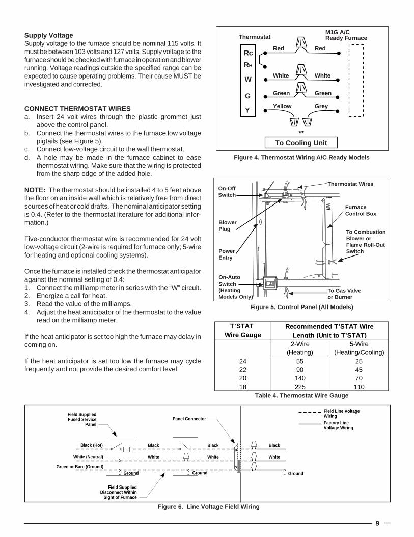
Supply VoltageSupply voltage to the furnace should be nominal 115 volts. Itmust be between 103 volts and 127 volts. Supply voltage to thefurnace should be checked with furnace in operation and blowerrunning. Voltage readings outside the specified range can beexpected to cause operating problems. Their cause MUST beinvestigated and corrected.
CONNECT THERMOSTAT WIRESa. Insert 24 volt wires through the plastic grommet just
above the control panel.b. Connect the thermostat wires to the furnace low voltage
pigtails (see Figure 5).c. Connect low-voltage circuit to the wall thermostat.d. A hole may be made in the furnace cabinet to ease
thermostat wiring. Make sure that the wiring is protectedfrom the sharp edge of the added hole.
NOTE: The thermostat should be installed 4 to 5 feet abovethe floor on an inside wall which is relatively free from directsources of heat or cold drafts. The nominal anticipator settingis 0.4. (Refer to the thermostat literature for additional infor-mation.)
Five-conductor thermostat wire is recommended for 24 voltlow-voltage circuit (2-wire is required for furnace only; 5-wirefor heating and optional cooling systems).
Once the furnace is installed check the thermostat anticipatoragainst the nominal setting of 0.4:1. Connect the milliamp meter in series with the “W” circuit.2. Energize a call for heat.3. Read the value of the milliamps.4. Adjust the heat anticipator of the thermostat to the value
read on the milliamp meter.
If the heat anticipator is set too high the furnace may delay incoming on.
If the heat anticipator is set too low the furnace may cyclefrequently and not provide the desired comfort level.
Figure 6. Line Voltage Field Wiring
T’STAT Wire Gauge
2-Wire 5-Wire(Heating) (Heating/Cooling)
24 55 2522 90 4520 140 7018 225 110
Recommended T’STAT WireLength (Unit to T’STAT )
Table 4. Thermostat Wire Gauge
Figure 5. Control Panel (All Models)
To CombustionBlower orFlame Roll-OutSwitch
Thermostat Wires
BlowerPlug
On-OffSwitch
On-AutoSwitch(HeatingModels Only)
To Gas Valveor Burner
PowerEntry
FurnaceControl Box
Figure 4. Thermostat Wiring A/C Ready Models
Rc
RH
W
G
Y
Red
White
Green
Yellow
Red
White
Green
Grey
**To Cooling Unit
ThermostatM1G A/CReady Furnace
Field SuppliedDisconnect Within
Sight of Furnace
Field SuppliedPanel Connector
Field SuppliedFused Service
Panel
Black (Hot)
White (Neutral)
Green or Bare (Ground)
Black
White
Black
White
Black
White
Field Line VoltageWiringFactory LineVoltage Wiring
Ground Ground Ground
10
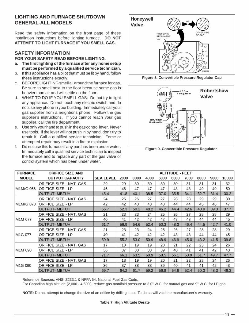
f. It is not necessary to convert the pilot orifice.g. For Honeywell gas valves with the regulator converter
(Figure 8), check for the letters NAT or LP on the pressureregulator cap. Unscrew the cap, invert it, replace, andtighten until snug.
h. For the Robertshaw gas valve with the regulator con-verter (Figure 9), remove the black cover and unscrewthe converter located on top of the gas valve. Invert theconverter. (For “LP” the red ring will be located at thebottom and the “LP” stamping on the converter will appearright side up.) Then screw converter back into the regu-lator, hand tight plus 1/8 turn, and replace the black coveronto the converter top to protect the threads.
i. Reassemble the burner assembly into the furnace.j. Reconnect the gas piping and electrical wires to the gas
valve.k. Open the manual shut-off valve and follow the FURNACE
START-UP procedure as outlined previously in this manualto put the furnace into operation.
NOTE: The pilot flame is adjustable by turning the adjustmentscrew located on the gas valve with a small screwdriver. (SeeFigure 10)
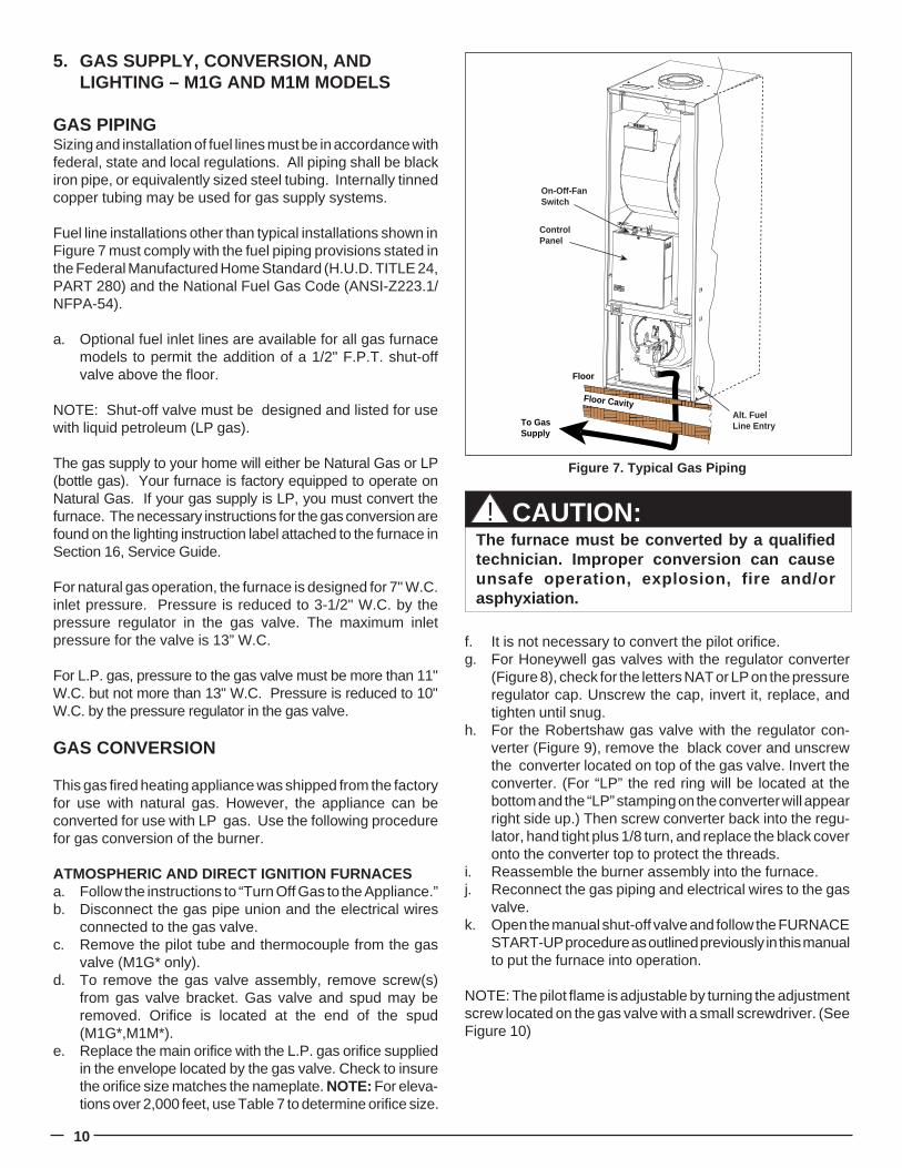
5. GAS SUPPLY, CONVERSION, ANDLIGHTING – M1G AND M1M MODELS
GAS PIPINGSizing and installation of fuel lines must be in accordance withfederal, state and local regulations. All piping shall be blackiron pipe, or equivalently sized steel tubing. Internally tinnedcopper tubing may be used for gas supply systems.
Fuel line installations other than typical installations shown inFigure 7 must comply with the fuel piping provisions stated inthe Federal Manufactured Home Standard (H.U.D. TITLE 24,PART 280) and the National Fuel Gas Code (ANSI-Z223.1/NFPA-54).
a. Optional fuel inlet lines are available for all gas furnacemodels to permit the addition of a 1/2" F.P.T. shut-offvalve above the floor.
NOTE: Shut-off valve must be designed and listed for usewith liquid petroleum (LP gas).
The gas supply to your home will either be Natural Gas or LP(bottle gas). Your furnace is factory equipped to operate onNatural Gas. If your gas supply is LP, you must convert thefurnace. The necessary instructions for the gas conversion arefound on the lighting instruction label attached to the furnace inSection 16, Service Guide.
For natural gas operation, the furnace is designed for 7" W.C.inlet pressure. Pressure is reduced to 3-1/2" W.C. by thepressure regulator in the gas valve. The maximum inletpressure for the valve is 13” W.C.
For L.P. gas, pressure to the gas valve must be more than 11"W.C. but not more than 13" W.C. Pressure is reduced to 10"W.C. by the pressure regulator in the gas valve.
GAS CONVERSION
This gas fired heating appliance was shipped from the factoryfor use with natural gas. However, the appliance can beconverted for use with LP gas. Use the following procedurefor gas conversion of the burner.
ATMOSPHERIC AND DIRECT IGNITION FURNACESa. Follow the instructions to “Turn Off Gas to the Appliance.”b. Disconnect the gas pipe union and the electrical wires
connected to the gas valve.c. Remove the pilot tube and thermocouple from the gas
valve (M1G* only).d. To remove the gas valve assembly, remove screw(s)
from gas valve bracket. Gas valve and spud may beremoved. Orifice is located at the end of the spud(M1G*,M1M*).
e. Replace the main orifice with the L.P. gas orifice suppliedin the envelope located by the gas valve. Check to insurethe orifice size matches the nameplate. NOTE: For eleva-tions over 2,000 feet, use Table 7 to determine orifice size.
To Gas Supply
Floor
ControlPanel
On-Off-FanSwitch
������������
Alt. FuelLine Entry
Floor Cavity
Figure 7. Typical Gas Piping
CAUTION:The furnace must be converted by a qualifiedtechnician. Improper conversion can causeunsafe operation, explosion, fire and/orasphyxiation.
!
11
LIGHTING AND FURNACE SHUTDOWNGENERAL-ALL MODELS
Read the safety information on the front page of theseinstallation instructions before lighting furnace. DO NOTATTEMPT TO LIGHT FURNACE IF YOU SMELL GAS.
SAFETY INFORMATIONFOR YOUR SAFETY READ BEFORE LIGHTING.a. The first lighting of the furnace after any home setup
must be performed by a qualified service technician.b. If this appliance has a pilot that must be lit by hand, follow
these instructions exactly.c. BEFORE LIGHTING smell all around the furnace for gas.
Be sure to smell next to the floor because some gas isheavier than air and will settle on the floor.
d. WHAT TO DO IF YOU SMELL GAS: Do not try to lightany appliance. Do not touch any electric switch and donot use any phone in your building. Immediately call yourgas supplier from a neighbor’s phone. Follow the gassupplier’s instructions. If you cannot reach your gassupplier, call the fire department.
e. Use only your hand to push in the gas control lever. Neveruse tools. If the lever will not push in by hand, don’t try torepair it. Call a qualified service technician. Force orattempted repair may result in a fire or explosion.
f. Do not use this furnace if any part has been under water.Immediately call a qualified service technician to inspectthe furnace and to replace any part of the gas valve orcontrol system which has been under water.
Reference Sources: ANSI Z233.1 & NFPA 54, National Fuel Gas Code.For Canadian high altitude (2,000 - 4,500'), reduce gas manifold pressure to 3.0” W.C. for natural gas and 9” W.C. for LP gas.
NOTE: Do not attempt to change the size of an orifice by drilling it out. To do so will void the manufacturer’s warranty.
Table 7. High Altitude Derate
Figure 8. Convertible Pressure Regulator Cap
PRESSURE REGULATOR CAP
M11678
NAT N
AT
L
P
L
P
NAT N
AT
OR
OTHER SIDEOF CAP
HoneywellValve
Figure 9. Convertible Pressure Regulator
RobertshawValve
FURNACE ORIFICE SIZE AND ALTITUDE - FEETMODEL OUTPUT CAPACITY SEA LEVEL 2000 3000 4000 5000 6000 7000 8000 9000 10000
ORIFICE SIZE - NAT. GAS 29 29 30 30 30 30 31 31 31 32M1M/G 056 ORIFICE SIZE - LP 45 46 47 47 47 48 48 49 49 50
OUTPUT- MBTUH 45.4 41.8 40.1 38.5 37.0 35.5 34.1 32.7 31.4 30.2ORIFICE SIZE - NAT. GAS 24 25 26 27 27 28 28 29 29 30
M1M/G 070 ORIFICE SIZE - LP 42 42 43 43 43 44 44 45 46 47OUTPUT- MBTUH 56.7 52.3 50.2 48.2 46.2 44.4 42.6 40.9 39.3 37.7ORIFICE SIZE - NAT. GAS 21 23 23 24 25 26 27 28 28 29
M1M 077 ORIFICE SIZE - LP 40 41 42 42 42 43 43 44 44 45OUTPUT- MBTUH 61.7 56.9 54.6 52.4 50.3 48.3 46.4 44.5 42.7 41.0ORIFICE SIZE - NAT. GAS 21 23 23 24 25 26 27 28 28 29
M1G 077 ORIFICE SIZE - LP 40 41 42 42 42 43 43 44 44 45OUTPUT- MBTUH 59.9 55.2 53.0 50.9 48.9 46.9 45.0 43.2 41.5 39.8ORIFICE SIZE - NAT. GAS 17 18 19 19 20 21 22 23 24 26
M1M 090 ORIFICE SIZE - LP 36 37 38 38 39 40 41 41 42 43OUTPUT- MBTUH 71.7 66.1 63.5 60.9 58.5 56.1 53.9 51.7 49.7 47.7ORIFICE SIZE - NAT. GAS 17 18 19 19 20 21 22 23 24 26
M1G 090 ORIFICE SIZE - LP 36 37 38 38 39 40 41 41 42 43OUTPUT- MBTUH 69.7 64.2 61.7 59.2 56.8 54.6 52.4 50.3 48.3 46.3
12
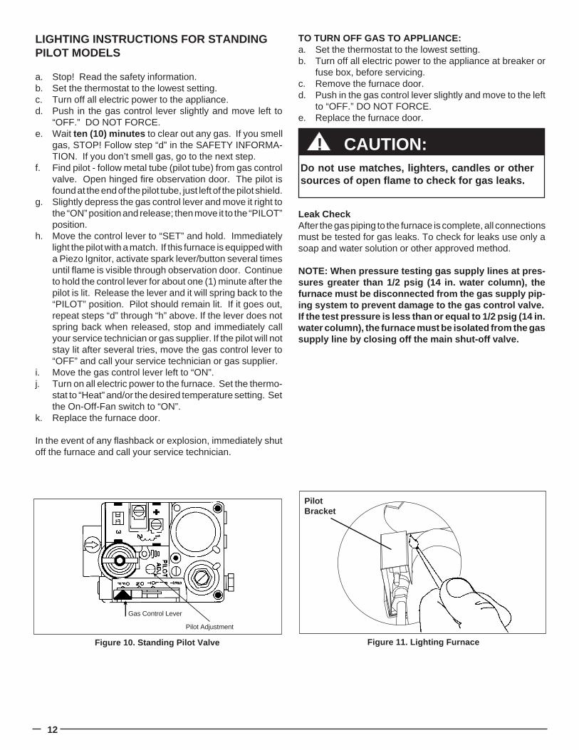
LIGHTING INSTRUCTIONS FOR STANDINGPILOT MODELS
a. Stop! Read the safety information.b. Set the thermostat to the lowest setting.c. Turn off all electric power to the appliance.d. Push in the gas control lever slightly and move left to
“OFF.” DO NOT FORCE.e. Wait ten (10) minutes to clear out any gas. If you smell
gas, STOP! Follow step “d” in the SAFETY INFORMA-TION. If you don’t smell gas, go to the next step.
f. Find pilot - follow metal tube (pilot tube) from gas controlvalve. Open hinged fire observation door. The pilot isfound at the end of the pilot tube, just left of the pilot shield.
g. Slightly depress the gas control lever and move it right tothe “ON” position and release; then move it to the “PILOT”position.
h. Move the control lever to “SET” and hold. Immediatelylight the pilot with a match. If this furnace is equipped witha Piezo Ignitor, activate spark lever/button several timesuntil flame is visible through observation door. Continueto hold the control lever for about one (1) minute after thepilot is lit. Release the lever and it will spring back to the“PILOT” position. Pilot should remain lit. If it goes out,repeat steps “d” through “h” above. If the lever does notspring back when released, stop and immediately callyour service technician or gas supplier. If the pilot will notstay lit after several tries, move the gas control lever to“OFF” and call your service technician or gas supplier.
i. Move the gas control lever left to “ON”.j. Turn on all electric power to the furnace. Set the thermo-
stat to “Heat” and/or the desired temperature setting. Setthe On-Off-Fan switch to “ON”.
k. Replace the furnace door.
In the event of any flashback or explosion, immediately shutoff the furnace and call your service technician.
TO TURN OFF GAS TO APPLIANCE:a. Set the thermostat to the lowest setting.b. Turn off all electric power to the appliance at breaker or
fuse box, before servicing.c. Remove the furnace door.d. Push in the gas control lever slightly and move to the left
to “OFF.” DO NOT FORCE.e. Replace the furnace door.
Leak CheckAfter the gas piping to the furnace is complete, all connectionsmust be tested for gas leaks. To check for leaks use only asoap and water solution or other approved method.
NOTE: When pressure testing gas supply lines at pres-sures greater than 1/2 psig (14 in. water column), thefurnace must be disconnected from the gas supply pip-ing system to prevent damage to the gas control valve.If the test pressure is less than or equal to 1/2 psig (14 in.water column), the furnace must be isolated from the gassupply line by closing off the main shut-off valve.
CAUTION:!Do not use matches, lighters, candles or othersources of open flame to check for gas leaks.
Figure 11. Lighting Furnace
PilotBracket
Gas Control Lever
Pilot Adjustment
Figure 10. Standing Pilot Valve
13
6. ACCESSORIES
Relay BoxesOnly the M1GH requires a relay box. All other M1G and M1Mfurnaces are AC ready. The M1GH series furnaces arecertified to be used with either a 4 wire relay box (p/n 902898A)or a 2 wire relay box (p/n 903092A). Follow the instructionsincluded with the relay box for proper installation.
Cooling BlowersIf you are installing an AC system which exceeds the maxi-mum AC capacity of your system, a larger blower will have tobe installed. A blower assembly may also need to be installedfor high static pressure applications or crossover systems.Refer to “Blower Data” for further information.
A/C CapacityBlower Wheel Motor-Hp Ton
903412 10 x 8 1/3 2, 2½ & 3903413 11 x 8 1/2 2, 2½, 3 & 4903414 10 x 8 3/4 2, 2½, 3, 4 & 5
Part No.Blower / Motor Assembly
Table 8. Field Installation Blower Assemblies
Fan Timer KitThe M1G furnace uses a temperature activated switch typefan control (The M1M uses a time delayed control, so thisinformation does not apply). A fan timer kit may need to beinstalled with this type of switch if the following conditionsexist:
1. Very cold outside air temperatures being drawn in throughthe VentilAire system.
2. Night time thermostat set back to a very low temperature.3. System is left off for extended periods of time.
The fan may be cycling during a normal call for heat. For gasmodels, make sure the gas valve is reaching high fire. If thereare no problems with the firing rate, install a Nordyne fan timerkit, part number 903490. See instructions with kit for installa-tion. Since many factors outside our control may contributeto blower short cycling, Nordyne does not consider this to bea warranty issue.
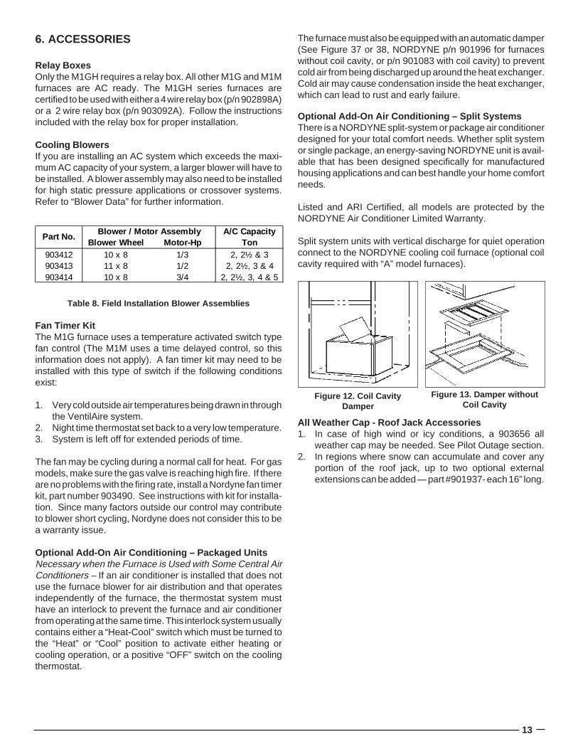
Optional Add-On Air Conditioning – Packaged UnitsNecessary when the Furnace is Used with Some Central AirConditioners – If an air conditioner is installed that does notuse the furnace blower for air distribution and that operatesindependently of the furnace, the thermostat system musthave an interlock to prevent the furnace and air conditionerfrom operating at the same time. This interlock system usuallycontains either a “Heat-Cool” switch which must be turned tothe “Heat” or “Cool” position to activate either heating orcooling operation, or a positive “OFF” switch on the coolingthermostat.
Figure 12. Coil CavityDamper
Figure 13. Damper withoutCoil Cavity
The furnace must also be equipped with an automatic damper(See Figure 37 or 38, NORDYNE p/n 901996 for furnaceswithout coil cavity, or p/n 901083 with coil cavity) to preventcold air from being discharged up around the heat exchanger.Cold air may cause condensation inside the heat exchanger,which can lead to rust and early failure.
Optional Add-On Air Conditioning – Split SystemsThere is a NORDYNE split-system or package air conditionerdesigned for your total comfort needs. Whether split systemor single package, an energy-saving NORDYNE unit is avail-able that has been designed specifically for manufacturedhousing applications and can best handle your home comfortneeds.
Listed and ARI Certified, all models are protected by theNORDYNE Air Conditioner Limited Warranty.
Split system units with vertical discharge for quiet operationconnect to the NORDYNE cooling coil furnace (optional coilcavity required with “A” model furnaces).
All Weather Cap - Roof Jack Accessories1. In case of high wind or icy conditions, a 903656 all
weather cap may be needed. See Pilot Outage section.2. In regions where snow can accumulate and cover any
portion of the roof jack, up to two optional externalextensions can be added — part #901937- each 16” long.
14
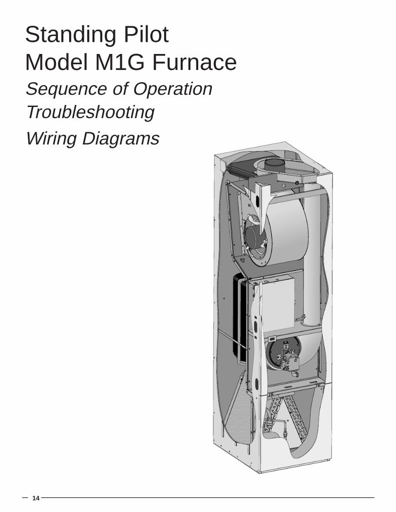
Standing PilotModel M1G FurnaceSequence of OperationTroubleshootingWiring Diagrams
15
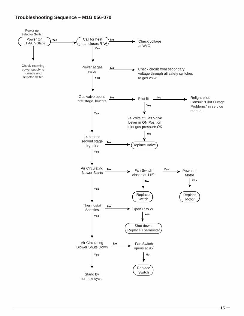
Call for heat,t-stat closes R-W
Power OnL1 A/C Voltage
No
Yes
Yes
Power up Selector Switch
Check incomingpower supply to
furnace andselector switch
No
Check voltageat WxC
Power at gasvalve
Check circuit from secondary voltage through all safety switches to gas valveYes
No NoGas valve opensfirst stage, low fire
Pilot lit Relight pilot.Consult "Pilot OutageProblems" in servicemanual
Yes
Yes
24 Volts at Gas ValveLever in ON PositionInlet gas pressure OK
Replace Valve
Yes
Yes
14 secondsecond stage
high fireNo
Yes
Yes
Air CirculatingBlower Starts
No
Yes
ThermostatSatisfies
No
No
Fan Switchcloses at 115˚
Power atMotor
Yes
ReplaceMotor
No
ReplaceSwitch
Open R to WYes
Shut down,Replace Thermostat
Air CirculatingBlower Shuts Down
Yes
Stand byfor next cycle
Fan Switchopens at 95˚
No
ReplaceSwitch
Troubleshooting Sequence – M1G 056-070
16
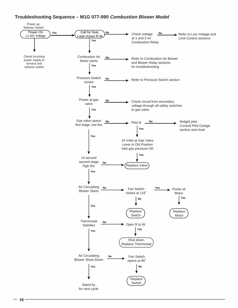
Call for heat,t-stat closes R-W
Power OnL1 A/C Voltage
No
Yes
Yes
Power up Selector Switch
Check incomingpower supply to
furnace andselector switch
No
Check voltageat 1 and 3 on Combustion Relay
Power at gasvalve
Check circuit from secondary voltage through all safety switches to gas valve
NoPressure Switchcloses
Refer to Pressure Switch section
Yes
Yes
No NoGas valve opensfirst stage, low fire
Pilot lit Relight pilotConsult Pilot Outagesection and chartYes
Yes
24 Volts at Gas ValveLever in ON PositionInlet gas pressure OK
Replace Valve
Yes
Yes
14 secondsecond stage
high fireNo
Yes
Yes
Air CirculatingBlower Starts
No
Yes
ThermostatSatisfies
No
No
Fan Switchcloses at 115˚
Power atMotor
Yes
ReplaceMotor
No
ReplaceSwitch
Open R to WYes
Shut down,Replace Thermostat
Air CirculatingBlower Shuts Down
Yes
Stand byfor next cycle
Fan Switchopens at 95˚
No
ReplaceSwitch
NoCombustion AirMotor starts
Refer to Combustion Air Blower and Blower Relay sectionsfor troubleshootingYes
No Refer to Low Voltage andLimit Control sections
Troubleshooting Sequence – M1G 077-090 Combustion Blower Model
17
7. Standing Pilot Model M1G
SEQUENCE OF OPERATION FOR STANDING PILOTa On a call for heat, the thermostat contacts close, supply-
ing 24 VAC to the gas valve.b. When the gas valve is energized it steps open at a
reduced flow and opens fully after approximately 14seconds.
c. When the call for heat is satisfied the thermostat contactsopen, the gas valve shuts off gas flow.
SEQUENCE OF OPERATION FOR STANDING PILOT W/INDUCED DRAFT BLOWERSa. On a call for heat, the thermostat contacts close, supply-
ing 24 VAC to the relay.b. The relay contacts close and energize the induced draft
motor.c. When the motor reaches full speed the pressure switch
closes and energizes the gas valve.d. When the gas valve is energized it steps open at a
reduced flow and opens fully after approximately 14seconds.
e. When the call for heat is satisfied the thermostat contactsopen, the gas valve shuts off gas flow, and the induceddraft blower stops.
TROUBLESHOOTING
Polarity and GroundThe furnace will not operate if loss of ground occurs. Everyeffort should be made at the installation to provide a goodground. If old 2-wire romex exists it should be replaced with a2-wire w/ground. A cold water line could be used provided thatthe connection or grounding occurs before any di-electricfittings and provided no plastic pipe is used inside or outsidethe building.
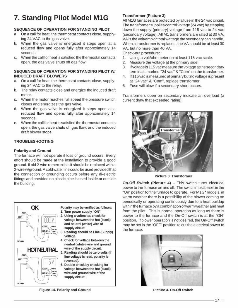
Transformer (Picture 3)All M1G furnaces are protected by a fuse in the 24 vac circuit.The transformer supplies control voltage (24 vac) by steppingdown the supply (primary) voltage from 115 vac to 24 vac(secondary voltage). All M1 transformers are rated at 30 VA.VA is the volt/amp or total wattage the secondary can handle.When a transformer is replaced, the VA should be at least 30VA, but no more than 40 VA.Check-out procedure:1. Using a volt/ohmmeter on at least 115 vac scale.2. Measure the voltage at the primary side.3. If voltage is 115 vac measure the voltage at the secondary
terminals marked "24 vac" & "Com" on the transformer.4. If 115 vac is measured at primary but no voltage is present
at "24 vac" & "Com", replace transformer.5. Fuse will blow if a secondary short occurs.
Transformers open on secondary indicate an overload (acurrent draw that exceeded rating).
Picture 3. Transformer
TransformerFuse
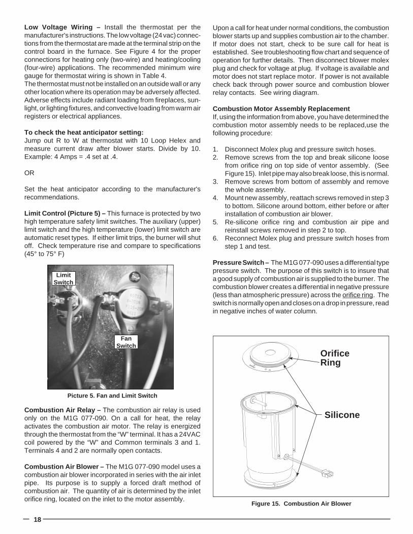
On-Off Switch (Picture 4) – This switch turns electricalpower to the furnace on and off. The switch must be set in the“On” position for the furnace to operate. For M1G* models, inwarm weather there is a possibility of the blower coming onperiodically or operating continuously due to a heat buildupwithin the furnace by a combination of warm weather and heatfrom the pilot. This is normal operation as long as there ispower to the furnace and the On-Off switch is at the “ON”position. If blower operation is not desired, the On-Off switchmay be set in the “OFF” position to cut the electrical power tothe furnace.
GROUND
NEUT.
HOT
OK
VOLTS AC
VOLTS DC
OHMSMICROAMPS
Volts Com Prep
GROUND
NEUT.
HOT
HOT NEUTRAL
VOLTS AC
VOLTS DC
OHMSMICROAMPS
Volts Com Prep
Polarity may be verified as follows:1. Turn power supply "ON"2. Using a voltmeter, check for
voltage between the hot (black) and neutral (white) wire of supply circuit.
3. Reading should be Line (Supply) Voltage.
4. Check for voltage between the neutral (white) wire and ground wire of the supply circuit.
5. Reading should be zero volts (if line voltage is read, polarity is reversed).
6. Double check by checking for voltage between the hot (black) wire and ground wire of the supply circuit.
Figure 14. Polarity and Ground Picture 4. On-Off Switch
18
Low Voltage Wiring – Install the thermostat per themanufacturer's instructions. The low voltage (24 vac) connec-tions from the thermostat are made at the terminal strip on thecontrol board in the furnace. See Figure 4 for the properconnections for heating only (two-wire) and heating/cooling(four-wire) applications. The recommended minimum wiregauge for thermostat wiring is shown in Table 4.The thermostat must not be installed on an outside wall or anyother location where its operation may be adversely affected.Adverse effects include radiant loading from fireplaces, sun-light, or lighting fixtures, and convective loading from warm airregisters or electrical appliances.
To check the heat anticipator setting:Jump out R to W at thermostat with 10 Loop Helex andmeasure current draw after blower starts. Divide by 10.Example: 4 Amps = .4 set at .4.
OR
Set the heat anticipator according to the manufacturer'srecommendations.
Limit Control (Picture 5) – This furnace is protected by twohigh temperature safety limit switches. The auxiliary (upper)limit switch and the high temperature (lower) limit switch areautomatic reset types. If either limit trips, the burner will shutoff. Check temperature rise and compare to specifications(45° to 75° F)
Combustion Air Relay – The combustion air relay is usedonly on the M1G 077-090. On a call for heat, the relayactivates the combustion air motor. The relay is energizedthrough the thermostat from the “W” terminal. It has a 24VACcoil powered by the “W” and Common terminals 3 and 1.Terminals 4 and 2 are normally open contacts.
Combustion Air Blower – The M1G 077-090 model uses acombustion air blower incorporated in series with the air inletpipe. Its purpose is to supply a forced draft method ofcombustion air. The quantity of air is determined by the inletorifice ring, located on the inlet to the motor assembly.
Upon a call for heat under normal conditions, the combustionblower starts up and supplies combustion air to the chamber.If motor does not start, check to be sure call for heat isestablished. See troubleshooting flow chart and sequence ofoperation for further details. Then disconnect blower molexplug and check for voltage at plug. If voltage is available andmotor does not start replace motor. If power is not availablecheck back through power source and combustion blowerrelay contacts. See wiring diagram.
Combustion Motor Assembly ReplacementIf, using the information from above, you have determined thecombustion motor assembly needs to be replaced,use thefollowing procedure:
1. Disconnect Molex plug and pressure switch hoses.2. Remove screws from the top and break silicone loose
from orifice ring on top side of ventor assembly. (SeeFigure 15). Inlet pipe may also break loose, this is normal.
3. Remove screws from bottom of assembly and removethe whole assembly.
4. Mount new assembly, reattach screws removed in step 3to bottom. Silicone around bottom, either before or afterinstallation of combustion air blower.
5. Re-silicone orifice ring and combustion air pipe andreinstall screws removed in step 2 to top.
6. Reconnect Molex plug and pressure switch hoses fromstep 1 and test.
Pressure Switch – The M1G 077-090 uses a differential typepressure switch. The purpose of this switch is to insure thata good supply of combustion air is supplied to the burner. Thecombustion blower creates a differential in negative pressure(less than atmospheric pressure) across the orifice ring. Theswitch is normally open and closes on a drop in pressure, readin negative inches of water column.
Picture 5. Fan and Limit Switch
LimitSwitch
FanSwitch
Figure 15. Combustion Air Blower
OrificeRing
Silicone
19
Under normal operating conditions, once the ventor motorbuilds up to speed sufficient differential (negative) pressure(approximately -0.30” wc) will be created to close the differen-tial pressure switch and keep it closed the whole heatingcycle. Under abnormal conditions, such as ventor motorfailure, or restricted air inlet or vent, sufficient differentialpressure will not be created.
Pressure switch check out procedure: 1. Remove orange wires from pressure switch. Place tees
in the bases connecting pressure switch to combustionblower assembly.
2. Connect a differential pressure gauge (magnehelic orequivalent) to the tees. The magnehelic connectionmarked low connects to the lower tee, and the onemarked high connects to the top tee.
3. Start motor.4. Negative pressure created by the forced draft motor must
be greater than -0.30” w.c. for the switch to close.5. Use the ohm meter to check for continuity across the
switch.6. If continuity is established, switch has closed. If ohm
meter shows infinite reading, and a pressure of -.30” w.c.or higher is present, switch is open, and must be replaced.
If the pressure differential reading will not pull down to -.30”w.c., possible causes could be:1. Restriction in air inlet pipe, this causes a greater negative
at the inlet side connection. This will act to open switch. Toprove this, disconnect the hose going to the top connection.If switch closes, there is too much negative pressure beingcreated on the inlet side. Look for air inlet restriction.
2. If there is a heat exchanger restriction or exhaust restriction(any restriction after motor), it will cause a lack of negativepressure. If flow out of chamber (exhaust) is poor no airwill be drawn in. Clean chamber and recheck.
3. If motor is not running, no negative will be created andassembly will have to be replaced. (See combustion airassembly replacement)
Burner Assembly – In order to perform procedures such asinspecting for presence of LP gas in chamber, changing thethermocouple, cleaning of pilot and burner, and inspecting theheat exchanger, the burner assembly must be removed.
Changing Complete Burner Assembly1. Gas Line - Remove the furnace door then disconnect and
remove the gas line from the valve body by using twobackup wrenches. Be careful not to damage the pipethreads or introduce dirt into the gas line.
2. Wiring Leads - Remove the two low voltage wiring leadsfrom the valve body by carefully pulling them off theconnectors. Be careful not to damage or dirty the connectorends.
3. Main Burner Mounting Plate- Using a philips screwdriver,remove the screws that hold the main burner mountingplate to the furnace.
4. Burner Assembly- Slide the burner assembly out from thefurnace.
5. Reverse procedure to reinstall.
NOTE: Be sure to install the gasket. If gasket becomesdamaged or torn, a replacement gasket kit is available.Contact your distributor for part number.
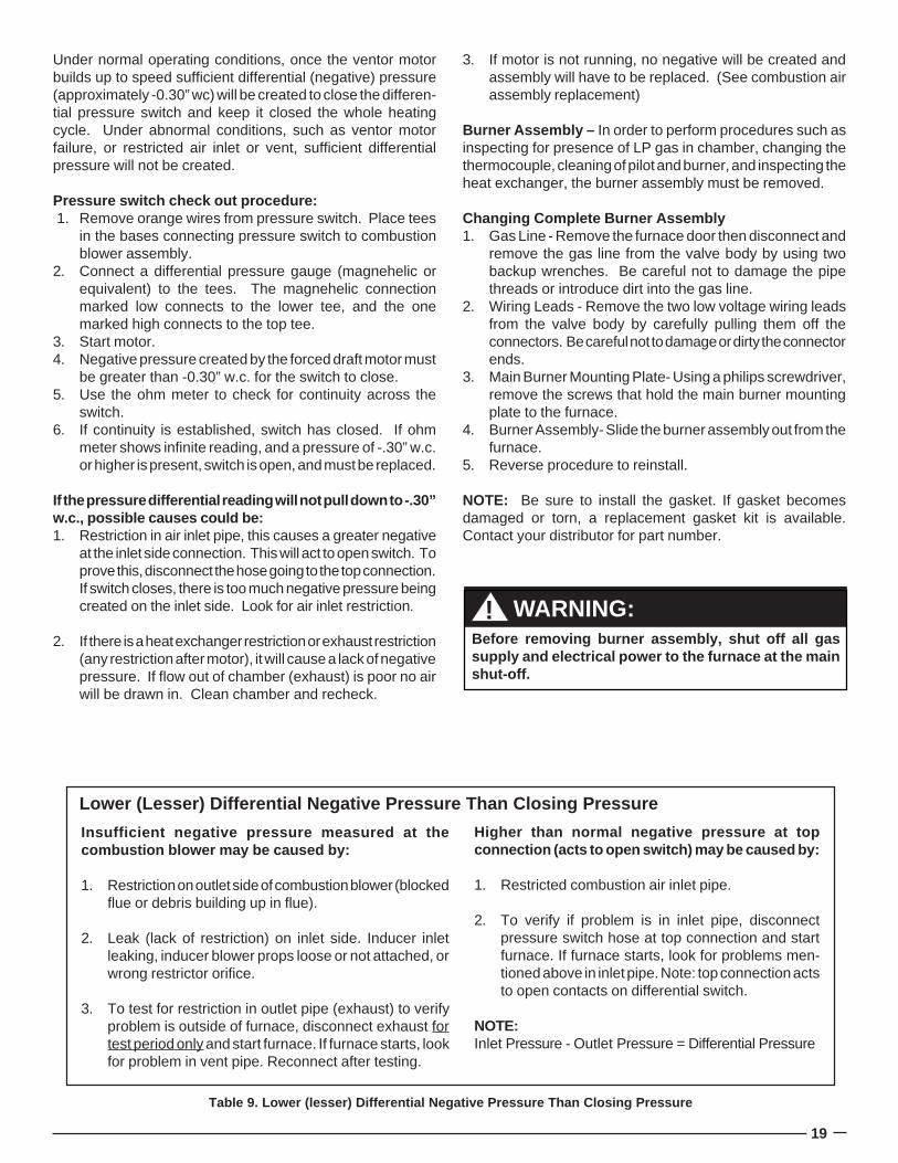
Table 9. Lower (lesser) Differential Negative Pressure Than Closing Pressure
Insufficient negative pressure measured at thecombustion blower may be caused by:
1. Restriction on outlet side of combustion blower (blockedflue or debris building up in flue).
2. Leak (lack of restriction) on inlet side. Inducer inletleaking, inducer blower props loose or not attached, orwrong restrictor orifice.
3. To test for restriction in outlet pipe (exhaust) to verifyproblem is outside of furnace, disconnect exhaust fortest period only and start furnace. If furnace starts, lookfor problem in vent pipe. Reconnect after testing.
Higher than normal negative pressure at topconnection (acts to open switch) may be caused by:
1. Restricted combustion air inlet pipe.
2. To verify if problem is in inlet pipe, disconnectpressure switch hose at top connection and startfurnace. If furnace starts, look for problems men-tioned above in inlet pipe. Note: top connection actsto open contacts on differential switch.
NOTE:Inlet Pressure - Outlet Pressure = Differential Pressure
Lower (Lesser) Differential Negative Pressure Than Closing Pressure
Before removing burner assembly, shut off all gassupply and electrical power to the furnace at the mainshut-off.
! WARNING:
20
Gas Valve - The gas valves for the gas furnaces are a 100%shut-off type and will fail safe if for some reason the gas isturned off. The valve is a “step-open” type for M1G*-models– which means it opens to a “low-fire” position, and after 14seconds, “steps-open” to “high-fire.”
A small orifice is placed in the gas passage to delay the buildup of the working pressure. A minimum of two minutes pausetime is required between cycles to allow the orifice time toexhaust all working gas from the diaphragm chamber andobtain full dwell time on subsequent cycles. Factory setnominal dwell time is approximately 14 seconds and is notfield adjustable.
Testing Operating Pressure:a. Remove furnace door and set the gas valve in the OFF
position.b. Using a 3/16” Allen wrench, remove the plug from the right
side of the valve.c. Install the barbed adapter in the plug hole. Tighten by
hand at first, then with an open end wrench. Do notovertighten!
d. Install the hose and manometer to the barbed fitting. Besure to check all connections for leaks.
e. Light the pilot by following the instructions on the furnaceand set the gas valve switch to the ON position.
f. With the valve in the ON position, set the thermostatabove room temperature so the furnace will run throughoutthe test procedure.
g. With the furnace operating, check for valve staging. Theoperating pressure should be approximately 3.5” WC forNatural Gas, 10” WC for LP gas.
Pilot Assembly, Thermocouple, and Venturi BurnerThe pilot lights the main burner. The thermocouple generatesaround 30 MV unloaded, (unscrewed from valve) and around15 MV loaded (screwed into valve). See gas valve and pilotoutage section for troubleshooting.
The pilot orifice is not changed when furnace is converted toLP (see conversion section). If the flame is more than about1” in height, it can be adjusted using the pilot adjustmentscrew. Turn the screw clockwise to decrease the flow rate,counterclockwise to increase it. Note: Do not confuse the pilotadjustment screw with the pressure regulator, which in-creases by turning clockwise and decreases by turning coun-terclockwise.
To clean pilot or service thermocouple or burner:1. Remove burner.2. Remove pilot assembly screws and pilot shield.3. Remove pilot tube from pilot assembly.4. Inspect pilot assembly - tap out pilot orifice and clean or
replace if plugged.5. Replace the pilot tube, shield, assembly screws, and
burner. Re-start and test.
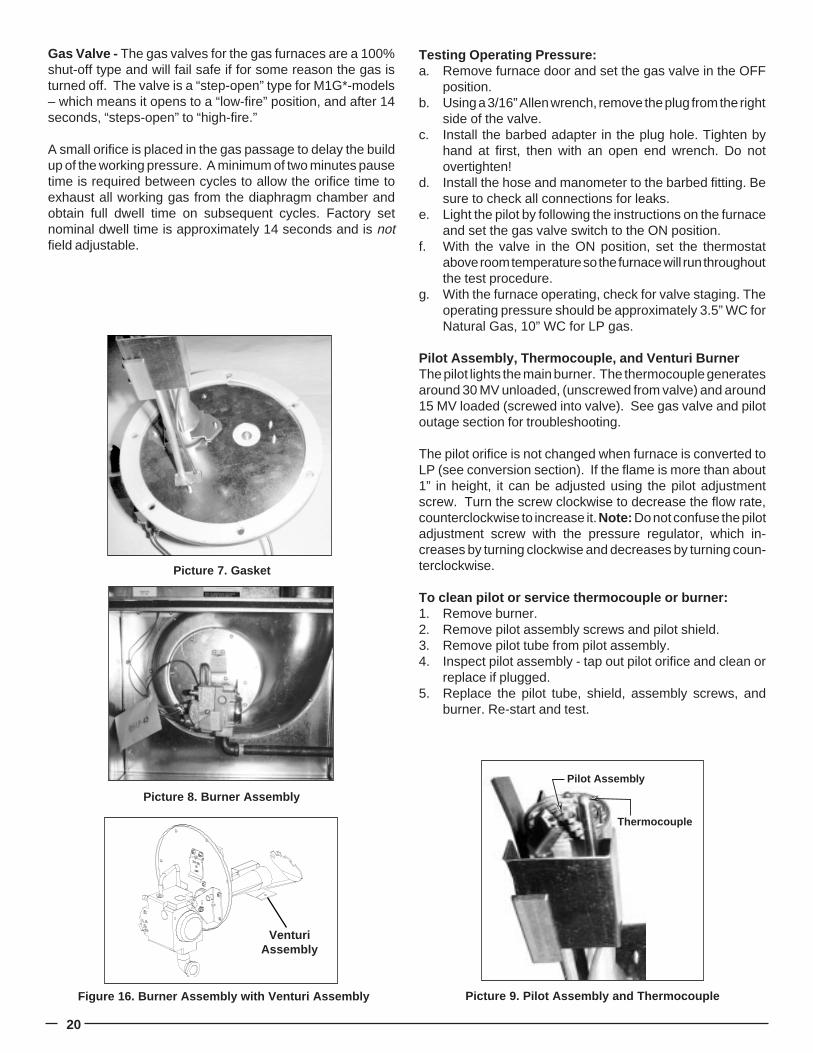
Figure 16. Burner Assembly with Venturi Assembly
VenturiAssembly
Picture 7. Gasket
Picture 8. Burner Assembly
Picture 9. Pilot Assembly and Thermocouple
Pilot Assembly
Thermocouple
21
To change thermocouple:1. Follow the same steps used to remove pilot assembly2. Remove pilot tube close-off plate by removing the phillips
screw on the burner plate.3. Note the height of the thermocouple in relationship to the
pilot before removal. It is critical to use the correct heightfor reinstallation. Disconnect thermocouple from gasvalve and pilot assembly.
4. Slide thermocouple out through hole left after pilot close-off plate was removed.
5. Reinstall new thermocouple and reverse steps from above.Note: Use hand to tighten thermocouple in gas valve, plus1/4” turn with wrench. Do not overtighten!
Venturi Burner AssemblyThe burner assembly consists of the burner, venturi andspreader. If burn through or other burner problem occurs,follow these steps to replace the burner:
1. Follow the steps under changing burner assembly.2. Disconnect pilot assembly by removing the two screws
holding pilot assembly and shield.3. Remove the two phillips screws holding the burner from
the round burner plate. Note that one is removed from thefront side and one from the back side.
4. Remove burner and flame spreader assembly.5. Install the new one by reversing steps 1 through 4.6. Start up and test.
Gas Valve Replacement1. Turn off gas and electric.2. Disconnect the two low voltage wires.3. Disconnect pilot tubing and thermocouple from gas valve.4. Remove the two screws from the gas valve mounting
plate.5. Remove gas valve and remove gas valve mounting.6. Remove spud holder threaded into valve.7. Repipe dope spud holder and tighten into new valve.8. Reverse steps through 5 and test.
Fan Switch (Picture 5) – The fan switch is a temperatureactuated, normally open switch that closes on temperaturerise and is in series with the heating speed of the air circulatingblower. Upon a call for heat, and when the burner builds upa supply of heat, the fan switch wraps closed at 115° (±5°) andblower motor starts. After the thermostat opens and thechamber cools down, the fan switch opens at 95° (±5°) andblower shuts off.
If blower does not start after warm up, check blower for power.If blower has power, see Blower Checkout section. If blowerdoes not have power, check for line voltage across the fanswitch. If voltage is present the switch is open. You also canremove wires, and ohm out after warm up. NOTE: Use tapeto make sure wires do not touch anything. An infinity readingindicates the switch is open.
If blower motor does not shut off and chamber has cooled (andfan switch is off), check across fan switch contacts. If there isno voltage, pull the single orange wire off (take care not totouch uninstalled terminal or lay wire against metal). If blowershuts off, fan switch is stuck closed. If switch does not closeor open properly, it will have to be replaced. Turn off power,remove wires, and remove the two phillips screws to removeswitch. Install new switch and re-test.
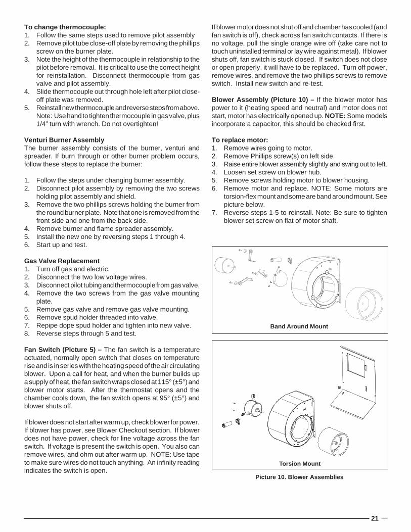
Blower Assembly (Picture 10) – If the blower motor haspower to it (heating speed and neutral) and motor does notstart, motor has electrically opened up. NOTE: Some modelsincorporate a capacitor, this should be checked first.
To replace motor:1. Remove wires going to motor.2. Remove Phillips screw(s) on left side.3. Raise entire blower assembly slightly and swing out to left.4. Loosen set screw on blower hub.5. Remove screws holding motor to blower housing.6. Remove motor and replace. NOTE: Some motors are
torsion-flex mount and some are band around mount. Seepicture below.
7. Reverse steps 1-5 to reinstall. Note: Be sure to tightenblower set screw on flat of motor shaft.
Band Around Mount
Picture 10. Blower Assemblies
Torsion Mount
22
Heat Exchanger Replacement – The heat exchanger is thelargest and most expensive item in the furnace. Beforereplacing the heat exchanger, make certain it is the problem.Call the technical service department if you have any uncer-tainty about a heat exchanger failure. Heat exchangers canbecome sooted up due to debris in top of furnaces,improper conversion, or not being converted to LP. Seetroubleshooting section on flue and conversion section ofthis manual. This condition is not covered under warranty.
To Test Heat Exchanger:Several methods may be used to test, or inspect for heatexchanger flaws.1. Remove the blower and burner. Visually inspect the heat
exchanger with a mirror. If you find a crack or hole in anypart of the heat exchanger, replace with out delay.
2. When the blower starts, observe the flame. If there is adisturbance in the flame, inspect and determine thecause.
3. Using a CO detector from the nearest register, monitorthe level for an increase while the unit runs. Single digitsof CO are common, but cigarette smoke, etc. can have animpact on the level. A rapid increase in the CO level whilethe furnace is running is not normal. If this occurs inspectthe heat exchanger.
Note: The furnace does not have to removed from its alcoveto replace the heat exchanger. Be sure to order the replace-ment gasket kit along with the heat exchanger. It contains allgaskets used in the furnace.
Change Out Procedure:1. Disconnect all gas and electrical power to furnace.2. Disconnect flue.3. Remove burner assembly.4. a. M1G-056-070 Only: Remove combustion air pipe.
b. M1G-077-090 Only: Remove combustion air pipe andcombustion blower.
5. Remove blower assembly.6. Remove blower deck panel. NOTE: Panel will be difficult
to remove with furnace in alcove.7. Remove front panel. NOTE: One of the panel screws is
located through the combustion air box on the right.8. Lift up divider panel out of side cabinet lances.9. Support the underside of the heat exchanger with a
board.10. Remove top collector panel. NOTE: Two screws attach
through top of cabinet.11. Remove the other eight screws in the top of the cabinet
that hold the combustion air box.12. Remove heat exchanger and replace.13. Reverse steps one through eleven to reinstall.
NOTE: Be sure to install all new gaskets (from gasketreplacement kit).
14. Start up and check out for proper operation.
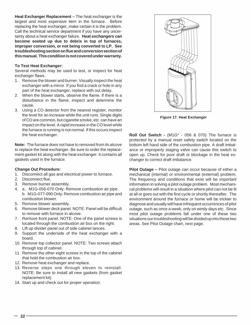
Figure 17. Heat Exchanger
Roll Out Switch - (M1G* - 056 & 070) The furnace isprotected by a manual reset safety switch located on thebottom left hand side of the combustion pipe. A draft imbal-ance or improperly staging valve can cause this switch toopen up. Check for poor draft or blockage in the heat ex-changer to correct draft imbalance.
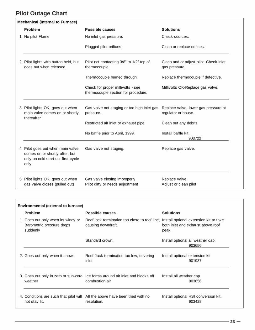
Pilot Outage – Pilot outage can occur because of either amechanical (internal) or environmental (external) problem.The frequency and conditions that exist will be importantinformation in solving a pilot outage problem. Most mechani-cal problems will result in a situation where pilot can not be litat all or goes out with the first cycle or shortly thereafter. Theenvironment around the furnace or home will be trickier todiagnose and usually will have infrequent occurrences of pilotoutage, such as once a week, only on windy days etc. Sincemost pilot outage problems fall under one of these twosituations our troubleshooting will be divided up into these twoareas. See Pilot Outage chart, next page.
23
Pilot Outage Chart
Problem Possible causes Solutions
1.
Standard crown. Install optional all weather cap.903656
2. Goes out only when it snows Install optional extension kit901937
3. Install all weather cap.903656
4. Install optional HSI conversion kit. 903428
Environmental (external to furnace)
Install optional extension kit to take both inlet and exhaust above roof peak.
Roof Jack termination too low, covering inlet
All the above have been tried with no resolution.
Goes out only when its windy or Barometric pressure drops suddenly
Goes out only in zero or sub-zero weather
Conditions are such that pilot will not stay lit.
Roof jack termination too close to roof line, causing downdraft.
Ice forms around air inlet and blocks off combustion air
Problem Possible causes Solutions
1. No pilot Flame No inlet gas pressure. Check sources.
Plugged pilot orifices. Clean or replace orifices.
2.
Thermocouple burned through. Replace thermocouple if defective.
Millivolts OK-Replace gas valve.
3.
Restricted air inlet or exhaust pipe. Clean out any debris.
No baffle prior to April, 1999. Install baffle kit.903722
4. Gas valve not staging. Replace gas valve.
5. Gas valve closing improperly Replace valvePilot dirty or needs adjustment Adjust or clean pilot
Clean and or adjust pilot. Check inlet gas pressure.
Pilot lights OK, goes out when main valve comes on or shortly thereafter
Gas valve not staging or too high inlet gas pressure.
Replace valve, lower gas pressure at regulator or house.
Pilot lights with button held, but goes out when released.
Pilot not contacting 3/8” to 1/2” top of thermocouple.
Mechanical (Internal to Furnace)
Pilot goes out when main valve comes on or shortly after, but only on cold start-up- first cycle only.
Pilot lights OK, goes out when gas valve closes (pulled out)
Check for proper millivolts - see thermocouple section for procedure.
24
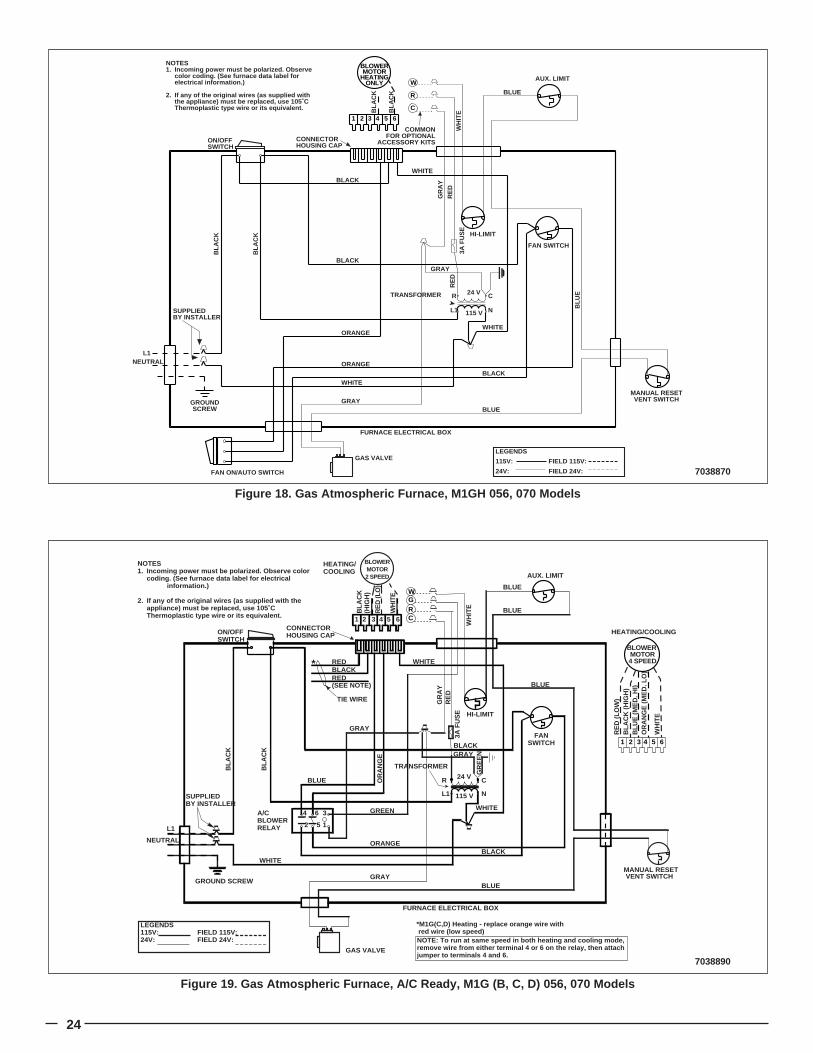
7038870
Figure 18. Gas Atmospheric Furnace, M1GH 056, 070 Models
ON/OFFSWITCH
GAS VALVE
FAN SWITCH
HI-LIMIT
AUX. LIMIT
TRANSFORMER
L1 N
CR 24 V
115 V
WHITE
WHITE
WHITE
GRAYBLUE
BLACK
GRAY
FAN ON/AUTO SWITCH
ORANGE
ORANGE
BLACK
L1NEUTRAL
GROUNDSCREW
FURNACE ELECTRICAL BOX
BLACK
3A F
US
E
BLOWERMOTOR
HEATINGONLY
654321
C
R
W
GR
AY
RE
D
BLU
E
CONNECTORHOUSING CAP
COMMONFOR OPTIONAL
ACCESSORY KITS
BLA
CK
BLA
CK
LEGENDS
115V: FIELD 115V:
24V: FIELD 24V:
RE
D
NOTES1. Incoming power must be polarized. Observe
color coding. (See furnace data label for electrical information.)
2. If any of the original wires (as supplied with the appliance) must be replaced, use 105˚C Thermoplastic type wire or its equivalent. B
LAC
K
BLA
CK
SUPPLIEDBY INSTALLER
BLUE
WH
ITE
MANUAL RESETVENT SWITCH
7038890
Figure 19. Gas Atmospheric Furnace, A/C Ready, M1G (B, C, D) 056, 070 Models
RE
D (L
OW
)B
LAC
K (H
IGH
)B
LUE
(ME
D. H
I)O
RA
NG
E (M
ED
. LO
)
152
A/CBLOWERRELAY
364
ON/OFFSWITCH
GAS VALVE
FANSWITCH
HI-LIMIT
AUX. LIMIT
TRANSFORMER
L1 N
CR 24 V
115 V
BLACK
ORANGE
BLUE OR
AN
GE
GREEN
WHITE
WHITE
WHITE
BLACK
GRAYBLUE
BLUE
BLACK
VENT SWITCH
BLUE
FURNACE ELECTRICAL BOX
L1
NEUTRAL
GROUND SCREW
HEATING/COOLING
CRGW
HEATING/COOLING
RED
RED(SEE NOTE)
TIE WIRE
CONNECTORHOUSING CAP
BLUE
GRAY
3A F
US
E
GR
AY
RE
D
654321
WH
ITE
654321
RE
D (L
O)
BLA
CK
(HIG
H)
WH
ITE
SUPPLIEDBY INSTALLER
LEGENDS115V: FIELD 115V:24V: FIELD 24V:
NOTES1. Incoming power must be polarized. Observe color
coding. (See furnace data label for electrical information.)
2. If any of the original wires (as supplied with the appliance) must be replaced, use 105˚C Thermoplastic type wire or its equivalent.
BLOWERMOTOR2 SPEED
BLOWER MOTOR4 SPEED
BLA
CK
BLA
CK
GRAY
GR
EE
N
WH
ITE
MANUAL RESET
*
*M1G(C,D) Heating - replace orange wire with red wire (low speed)NOTE: To run at same speed in both heating and cooling mode, remove wire from either terminal 4 or 6 on the relay, then attach jumper to terminals 4 and 6.
25
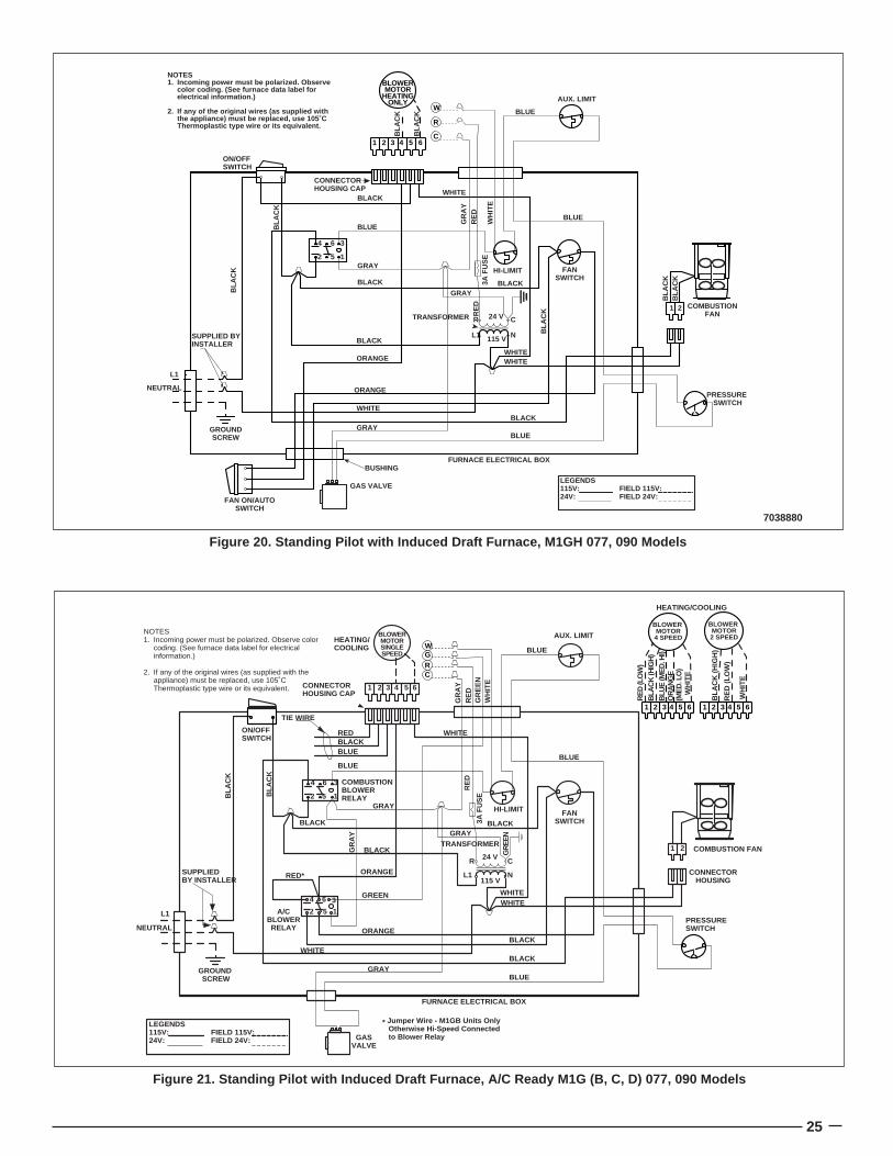
Figure 21. Standing Pilot with Induced Draft Furnace, A/C Ready M1G (B, C, D) 077, 090 Models
654321
152
A/CBLOWERRELAY
364
152
COMBUSTIONBLOWERRELAY
364
ON/OFFSWITCH
GASVALVE
HI-LIMIT
AUX. LIMIT
TRANSFORMER
PRESSURESWITCH
COMBUSTION FAN
L1 N
CR 24 V
115 V
BLACK
BLACKBLACK
BLACK
BLACKORANGE
ORANGE
GREENWHITE
WHITE
WHITE
WHITE
GRAY
GRAYBLUE
BLUE
21
GRAY
L1
NEUTRAL
GROUND SCREW
FURNACE ELECTRICAL BOX
REDBLACKBLUE
TIE WIRE
HEATING/COOLING BLUE
CRGW
FANSWITCH
BLUE
RED* CONNECTORHOUSING
GR
AY
3A F
US
E
GR
EEN
LEGENDS115V: FIELD 115V:24V: FIELD 24V:
NOTES1. Incoming power must be polarized. Observe color
coding. (See furnace data label for electrical information.)
2. If any of the original wires (as supplied with the appliance) must be replaced, use 105˚C Thermoplastic type wire or its equivalent.
BLOWERMOTORSINGLESPEED
HEATING/COOLING
654321
RE
D (L
OW
)B
LAC
K (H
IGH
)B
LUE
(ME
D. H
I)O
RA
NG
E
(ME
D. L
O)
WH
ITE
BLOWER MOTOR4 SPEED
654321
RE
D (
LOW
)
BLA
CK
(H
IGH
)
WH
ITE
CONNECTORHOUSING CAP
SUPPLIEDBY INSTALLER
* Jumper Wire - M1GB Units Only Otherwise Hi-Speed Connected to Blower Relay
GR
AY
RE
DG
RE
EN
WH
ITE
BLA
CK
BLA
CK
RE
D
BLOWER MOTOR2 SPEED
7038880
Figure 20. Standing Pilot with Induced Draft Furnace, M1GH 077, 090 Models
152
364
GAS VALVE
FANSWITCH
HI-LIMIT
AUX. LIMIT
PRESSURE SWITCH
COMBUSTIONFAN
L1 N
CR 24 V
115 V
BLACKBLACK
BLACK
BLUE
BLACK
WHITE
WHITE
WHITE
WHITE
GRAY
GRAYBLUE
BLUE
21
GRAY
SUPPLIED BYINSTALLER
FAN ON/AUTOSWITCH
BLUE
BLACK
ORANGE
ORANGE
L1
NEUTRAL
GROUNDSCREW
FURNACE ELECTRICAL BOX
3A F
US
E
BUSHINGR
ED
C
R
W
ON/OFFSWITCH
CONNECTORHOUSING CAP
BLA
CK
BLA
CK
LEGENDS115V: FIELD 115V:24V: FIELD 24V:
GR
AY
RE
D
WH
ITE
BLA
CK
BLA
CK
BLA
CK
TRANSFORMER
BLOWERMOTOR
HEATINGONLY
654321
BLA
CK
BLA
CK
NOTES1. Incoming power must be polarized. Observe
color coding. (See furnace data label for electrical information.)
2. If any of the original wires (as supplied with the appliance) must be replaced, use 105˚C Thermoplastic type wire or its equivalent.
26
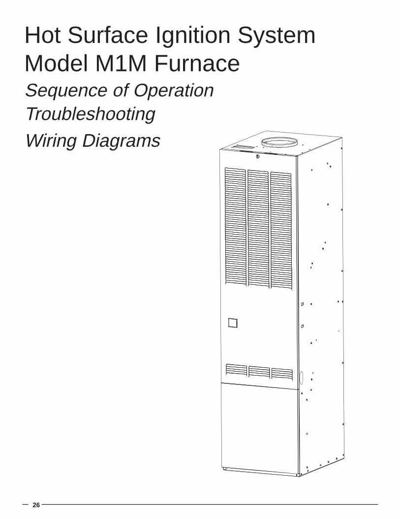
Hot Surface Ignition SystemModel M1M FurnaceSequence of OperationTroubleshootingWiring Diagrams
27
Call for heat,t-stat closes R-W
Check for red light on circuit board
24 Volt, C to W on circuit board
Polarity is reversed
Switch L1 & L2
Inducer starts
Check fuse on circuit board, replace if no continuity
Check for voltageat inducer molex plug
Pressure switch stuck closed
ReplaceBoard
Replace pressure switch
Circuit board 3 blinks
Check for voltageat molex plug
Replace InducerBlower
Pressure switch closes within 10 seconds
Circuit board blinks 2 times
Is there >8mA on W terminal of circuit board? Replace t-stat or add isolation relay.
Pressure switch open
Inducer pre-purges for 45 seconds
Greater than-.30" W.C.
differential at pressure switch
Replace pressure switch
Check venting
Ignitor heats upand glows for 30 seconds
Gas valve open
Do Burners Light
Ignitor turns off 7 seconds after gas valve opens
Main blower starts after delay time (30 seconds)
Flame, inducer, main blowerstay on until call for heat ends
Replace ignitor
Replace circuit board
24 volts at gas valve.Insure lever is in
ON position. Insure gas inlet pressure is below 14" W.C.
Replace gas valve
Manifold Gas Pressure Available
Burners stay on longer than 6 seconds
Check and adjust ignitorgap to 5/16"
Will retry 4 more times.Soft lock out blinks 4 times
on status light.Power down andback up to reset.
Replace board
Flame light on
Replace circuit boardCheck for voltage atcom and heat terminals
Replace circuit board
Yes
Yes
Yes
Yes
Yes
YesYes
Yes
Yes
Yes
Yes
Yes
Yes
Yes
Yes
Yes
Yes
Yes
Yes
Yes
Yes
Yes
Check motorand capacitor
Yes
No
No No
No
No
No
No
No No
No
No No
No
NoFlashing
OFF
No
No No
No No
Is light blinking5 times?
Adjust ignitor gap to 5/16"Check ground circuit to Furnace.
Flame light blinks at1 uA(weak signal)
Note: RetryEvery Hour
Inducer post-purges for 30 seconds
Main Blower Fan Off Timing
Troubleshooting Sequence – M1M
28
8. Hot Surface Ignition System Model M1M
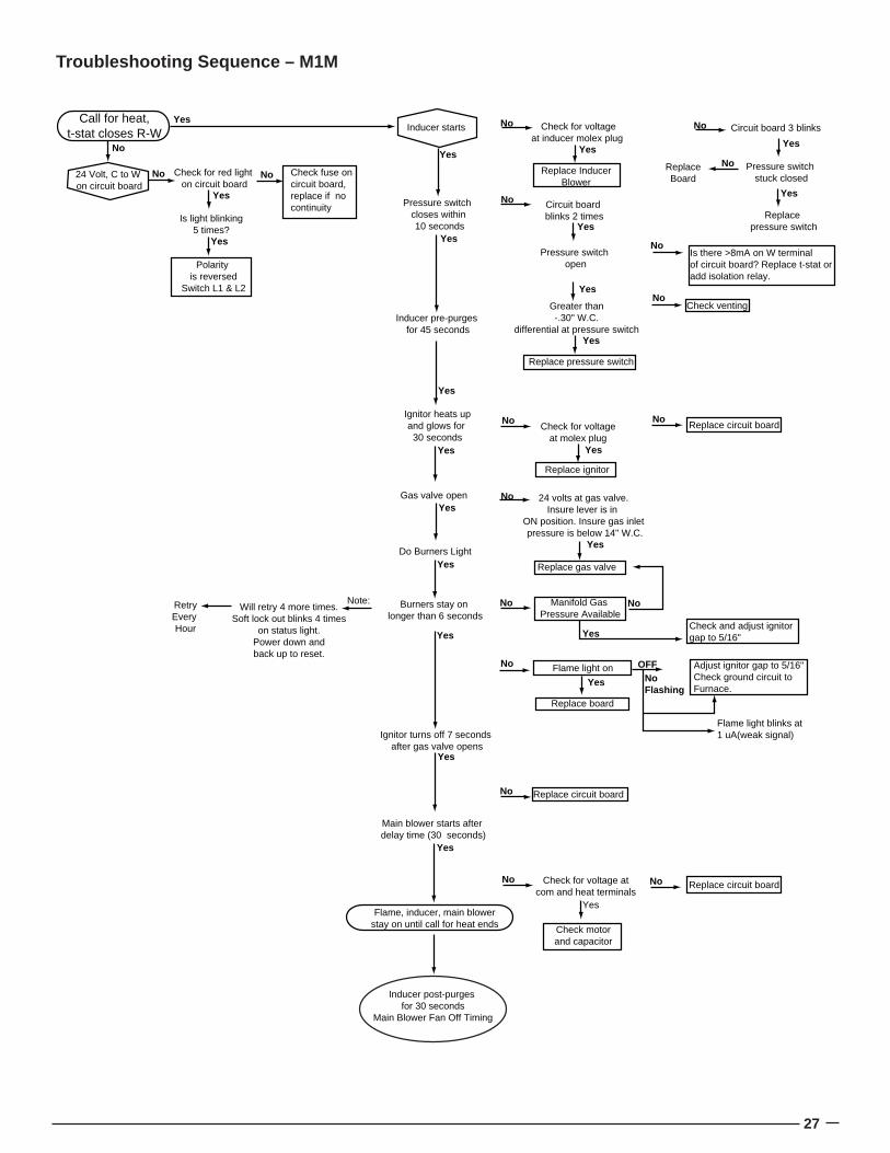
SEQUENCE OF OPERATION M1M SERIESCall for heat: the thermostat calls for heat by energizing the“W” terminal. The control checks to see the pressure switchis open. If the pressure switch is closed when the call for heatoccurs, the control will begin to flash “3” on the Status LEDafter 10 seconds and wait indefinitely for the pressure switchto open.
Pressure switch proving: the control energizes the induceddraft motor and waits for the pressure switch to close. If thepressure switch does not close within 10 seconds of theinducer energizing, the control will begin to flash “2” on theStatus LED and wait indefinitely for the pressure switch toclose.
Pre-purge: the control runs the inducer for a 45 second pre-purge time.
HSI warm up: the control energizes the HSI for 30 seconds.The inducer remains energized.
Ignition activation period: the control energizes the main gasvalve for 6 seconds. The inducer and HSI remain energized.
Flame proving: the control de-energizes the hot surfaceignitor. The gas valve and inducer remain energized. If flameis present 1 second after HSI de-energizes, the control goesto blower on delay. If a flame is not present, the control de-energizes the gas valve and proceeds with ignition retries asspecified below.
Blower on delay: If flame is present, the control energizes theblower on HEAT speed 30 seconds after the gas valveopened (24 seconds from HSI off). The gas valve and inducerremain energized.
Steady heat: Control inputs are continuously monitored toensure limit and pressure switches are closed, flame isestablished, and the thermostat call for heat remains.
Post purge: When the thermostat demand for heat is satisfied,the control de-energizes the gas valves. The inducer outputremains on for a 30 second post-purge period.
Blower off delay: The indoor blower motor is de-energizedafter a 120 second blower off delay. Blower timing beginswhen the thermostat is satisfied.
COMPONENT PARTS
TROUBLESHOOTINGPolarity and GroundThe furnace will not operate if loss of ground occurs. Everyeffort should be made at the installation to provide a goodground. If old 2-wire romex exists it should be replaced with a2-wire w/ground. A cold water line could be used provided thatthe connection or grounding occurs before any di-electricfittings and provided no plastic pipe is used inside or outsidethe building.
Transformer (See Figure 21) – The transformer suppliescontrol voltage (24 vac) by stepping down the supply (pri-mary) voltage from 115 vac to 24 vac (secondary voltage).Transformers are rated by VA. VA is the volt/amp or totalwattage the secondary can handle. When a transformer isreplaced the VA should be of an equal or greater value.Check-out procedure:1. Using a volt/ohmmeter on at least 115 vac scale.2. Measure the voltage on the control board terminals
"XFMR" & "NEUTRAL".3. If voltage is 115 vac measure the voltage at terminals
marked "24 vac" & "Com" located in the center of thecontrol board.
4. If 115 vac is measured at "XFMR" & "NEUTRAL" but novoltage is present at "24 vac" & "Com" replace transformer.
GROUND
NEUT.
HOT
OK
VOLTS AC
VOLTS DC
OHMSMICROAMPS
Volts Com Prep
GROUND
NEUT.
HOT
HOT NEUTRAL
VOLTS AC
VOLTS DC
OHMSMICROAMPS
Volts Com Prep
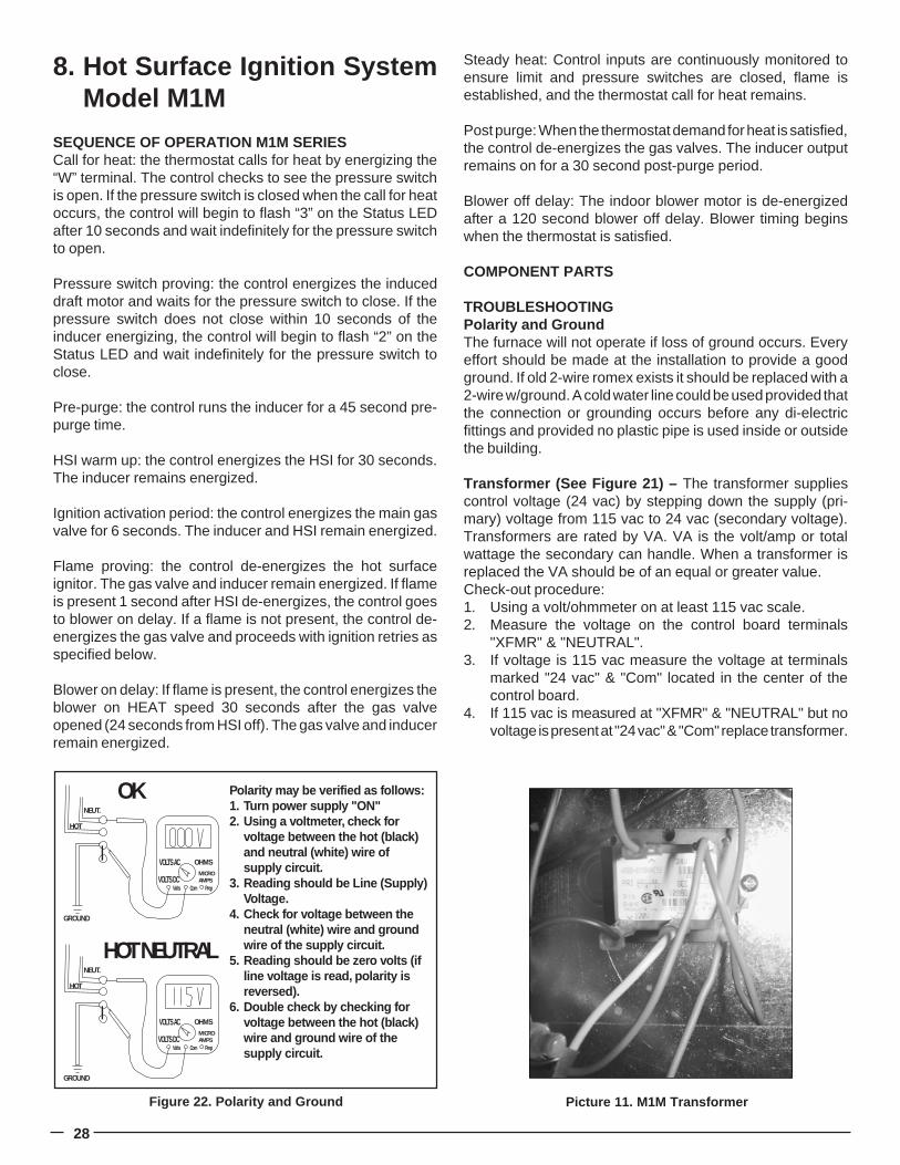
Polarity may be verified as follows:1. Turn power supply "ON"2. Using a voltmeter, check for
voltage between the hot (black) and neutral (white) wire of supply circuit.
3. Reading should be Line (Supply) Voltage.
4. Check for voltage between the neutral (white) wire and ground wire of the supply circuit.
5. Reading should be zero volts (if line voltage is read, polarity is reversed).
6. Double check by checking for voltage between the hot (black) wire and ground wire of the supply circuit.
Figure 22. Polarity and Ground Picture 11. M1M Transformer
29
Transformers open on primary indicate low voltage shortcircuit. Transformers open on secondary indicate an overload(a current draw that exceeded rating).
Low Voltage WiringInstall the thermostat per the manufacturer's instructions. Thelow voltage (24 vac) connections from the thermostat aremade at the pigtail wires coming off the control board in thefurnace. See Figure 23 for the proper connections for heatingonly (two-wire) and heating/cooling (four-wire) applications.The recommended minimum wire gauge for thermostat wiringis shown in Table 5.
The thermostat must not be installed on an outside wall or anyother location where its operation may be adversely affected.Adverse effects include radiant loading from fireplaces, sun-light, or lighting fixtures, and convective loading from warm airregisters or electrical appliances.
To check the heat anticipator setting:Jump out R to W at thermostat with 10 Loop Helex andmeasure current draw after blower starts. Divide by 10.Example: 4 Amps = .4 set at .4.
Limit Control (Picture 14) – This furnace is protected by twohigh temperature safety limit switches. The auxiliary (upper)limit switch and the high temperature (lower) limit switch areautomatic reset types. If either limit trips, the burner will shutoff, and status light will flash “1”.
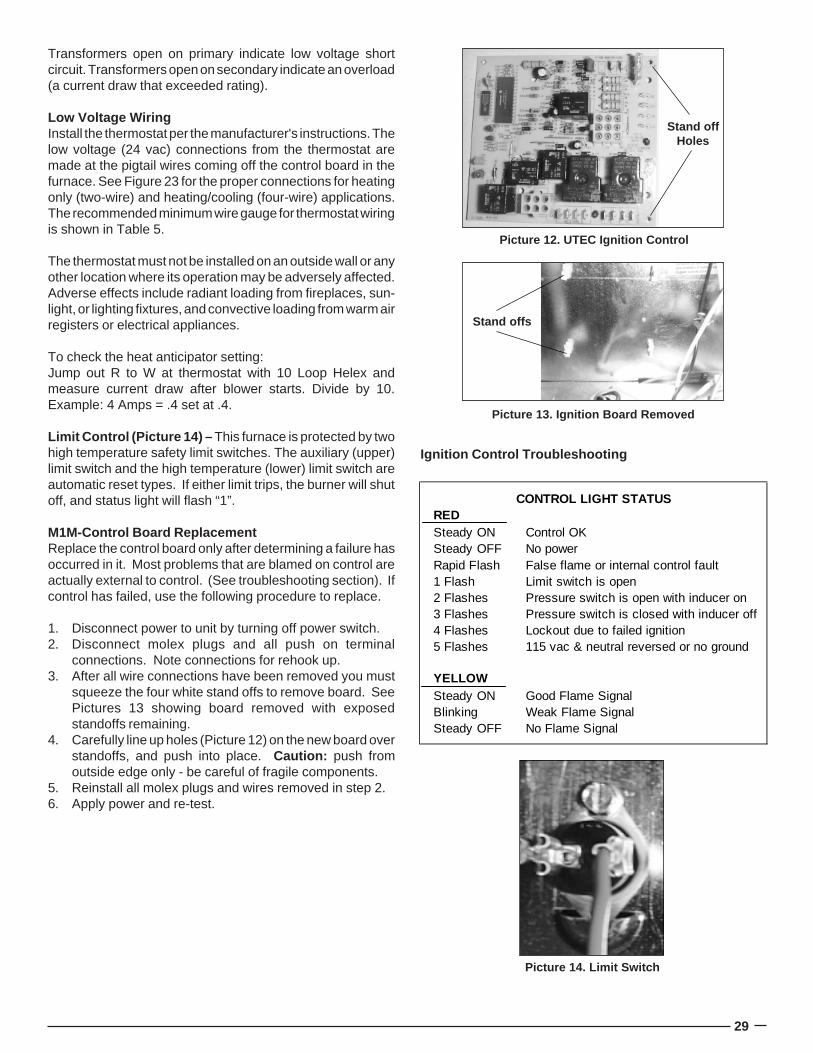
M1M-Control Board ReplacementReplace the control board only after determining a failure hasoccurred in it. Most problems that are blamed on control areactually external to control. (See troubleshooting section). Ifcontrol has failed, use the following procedure to replace.
1. Disconnect power to unit by turning off power switch.2. Disconnect molex plugs and all push on terminal
connections. Note connections for rehook up.3. After all wire connections have been removed you must
squeeze the four white stand offs to remove board. SeePictures 13 showing board removed with exposedstandoffs remaining.
4. Carefully line up holes (Picture 12) on the new board overstandoffs, and push into place. Caution: push fromoutside edge only - be careful of fragile components.
5. Reinstall all molex plugs and wires removed in step 2.6. Apply power and re-test.
Ignition Control Troubleshooting
REDSteady ON Control OKSteady OFF No powerRapid Flash False flame or internal control fault1 Flash Limit switch is open2 Flashes Pressure switch is open with inducer on3 Flashes Pressure switch is closed with inducer off4 Flashes Lockout due to failed ignition5 Flashes 115 vac & neutral reversed or no ground
YELLOWSteady ON Good Flame SignalBlinking Weak Flame SignalSteady OFF No Flame Signal
CONTROL LIGHT STATUS
Picture 14. Limit Switch
Picture 12. UTEC Ignition Control
Stand offHoles
Picture 13. Ignition Board Removed
Stand offs

30
1. Power Line Polarity – The “hot” side of the power linemust be connected to the “L1” for the control to be able tosense flame. The control detects the reversal of “hot” andneutral. When L1 and Neutral are switched (or L1 is notpresent), the control flashes “5” on the Status LED andlocks out.
2. Interrupted Thermostat – If the thermostat demand forheat is removed before the flame recognition period, thecontrol will run the inducer for the post purge period andde-energize all outputs.
3. Ignition Re-Try – If flame is not established on the firsttrial for ignition period, the gas valve is de-energized andthe inducer remains energized for an inter-purge period of30 seconds. The ignitor is then re-energized and thecontrol initiates another trial for ignition. This sequencerepeats for up to 5 trials for ignition.
4. Ignition Re-Cycle – Flame must not be sensed for 1second before the control responds to a loss of flame. Ifflame is established and maintained during the trial forignition period and then flame is lost, the gas valve is de-energized within 2 seconds, the induced draft motorcontinues to run, and the control begins timing the 45second inter-purge delay. The indoor blower motor will beenergized and/or remain energized on heat speed for theselected delay off time.
When the inter-purge delay is over, the ignitor is re-energized, and the control initiates another ignitor warmup and ignition activation period. The control will re-cycleup to 5 flame losses (4 re-cycles) within a single call forheat before going to lockout.
5. Call for Continuous Fan/Cooling – When a thermostatcall for continuous fan (G) without a call for heat orcooling, the indoor fan is energized on the COOL speedafter a .25 second delay. If a call for heat (W) occursduring continuous fan, the blower will de-energize.
A call for fan is ignored while in lockout.
6. Limit Switch Operation – Any time the limit switchopens, the gas valve and ignitor will be de-energized, theindoor blower motor will run on heat speed, and induceddraft motor will run continuously. Control status LEDflashes “1.”
When the switch re-closes, the induced draft motor willrun through post-purge and the indoor blower will runthrough the selected fan off delay. The control will returnto normal operation after the blower off delay is completed.
7. Pressure Switch – The control shall ignore pressureswitch openings of less than 1 second (the gas valve willmomentarily de-energize while the pressure switch isopen, this may cause a loss of flame). To prevent pressureswitch faults from being treated as flame losses, thecontrol checks to see if the pressure switch has been
open momentarily within 2 seconds prior to the flame loss.If the pressure switch was open any time within the 2seconds prior to a flame loss, the control assumes theflame loss was due to the open pressure switch andresponds as described below.
If the pressure switch opens for more than 1 second afterflame has been established, the control shall de-energizethe gas valve, run through a normal 30 second post-purgeand selected heat blower off delay. When the blower offdelay is complete, the control shall start an ignitionsequence if the thermostat is still calling for heat.
If the pressure switch opens for more than one secondduring a pre-purge or inter-purge, the control shall wait forthe pressure switch to close. The purge time re-startswhen the pressure switch closes. The control status LEDwill flash “2.” If the pressure switch is closed when the callfor heat occurs, the control will begin to flash “3” on thestatus LED after 10 seconds and wait indefinitely for thepressure switch to open.
8. Flame sense – Flame is normally sensed through the hotsurface ignitor using flame rectification. Open circuitflame sense voltage should be approximately 120 VACline voltage. Minimum flame current required to senseflame is 0.5 microamps DC. Normal microamps is 3 orhigher. To test, install microamp meter in series withground (9) pin. If flame light is on solid microamp signal isat least 1 microamp. If flame light is blinking, flame signalis between 0.5 and 1 microamp, indicating a weak signal.Check for ignitor positioning and proper ground.
9. Undesired Flame – If flame is sensed longer than 4seconds while the gas valve is de-energized, the controlshall energize the induced draft motor and indoor bloweron heat speed. When flame is no longer sensed, theinduced draft motor will run through post-purge and theindoor blower motor will run through the selected heat fanoff delay time. The control will do a soft lockout, but will stillrespond to open limit and flame. The Status LED will flashrapidly when lockout is due to undesired flame.
10. Lockout – The control shall not initiate a call for heat orcall for continuous fan while in lockout. A call for coolingoperates as normal. The control will still respond to anopen limit and undesired flame.
Lockout will automatically reset after 1 hour. Lockout maybe manually reset by removing power from the control formore than 1 second or removing the thermostat call forheat for more than 1 and less than 20 seconds (The 20second time limit prevents electronic thermostats fromautomatically resetting lockout).
11. Power Interruption – The control will not interrupt itsoperational sequence from power interruptions less than80 mS in duration. Relay outputs will momentarily de-energize during the interruption.
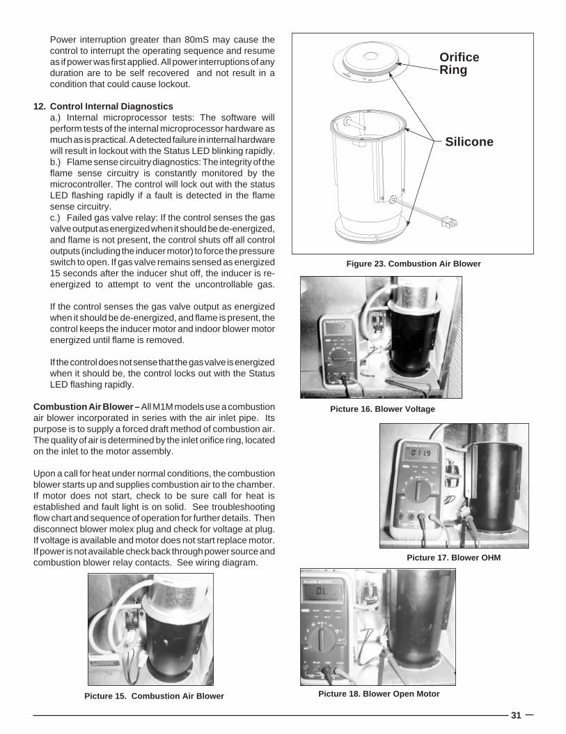
31
Power interruption greater than 80mS may cause thecontrol to interrupt the operating sequence and resumeas if power was first applied. All power interruptions of anyduration are to be self recovered and not result in acondition that could cause lockout.
12. Control Internal Diagnosticsa.) Internal microprocessor tests: The software willperform tests of the internal microprocessor hardware asmuch as is practical. A detected failure in internal hardwarewill result in lockout with the Status LED blinking rapidly.b.) Flame sense circuitry diagnostics: The integrity of theflame sense circuitry is constantly monitored by themicrocontroller. The control will lock out with the statusLED flashing rapidly if a fault is detected in the flamesense circuitry.c.) Failed gas valve relay: If the control senses the gasvalve output as energized when it should be de-energized,and flame is not present, the control shuts off all controloutputs (including the inducer motor) to force the pressureswitch to open. If gas valve remains sensed as energized15 seconds after the inducer shut off, the inducer is re-energized to attempt to vent the uncontrollable gas.
If the control senses the gas valve output as energizedwhen it should be de-energized, and flame is present, thecontrol keeps the inducer motor and indoor blower motorenergized until flame is removed.
If the control does not sense that the gas valve is energizedwhen it should be, the control locks out with the StatusLED flashing rapidly.
Combustion Air Blower – All M1M models use a combustionair blower incorporated in series with the air inlet pipe. Itspurpose is to supply a forced draft method of combustion air.The quality of air is determined by the inlet orifice ring, locatedon the inlet to the motor assembly.
Upon a call for heat under normal conditions, the combustionblower starts up and supplies combustion air to the chamber.If motor does not start, check to be sure call for heat isestablished and fault light is on solid. See troubleshootingflow chart and sequence of operation for further details. Thendisconnect blower molex plug and check for voltage at plug.If voltage is available and motor does not start replace motor.If power is not available check back through power source andcombustion blower relay contacts. See wiring diagram.
Picture 18. Blower Open Motor
Picture 17. Blower OHM
Picture 15. Combustion Air Blower
Figure 23. Combustion Air Blower
OrificeRing
Silicone
Picture 16. Blower Voltage
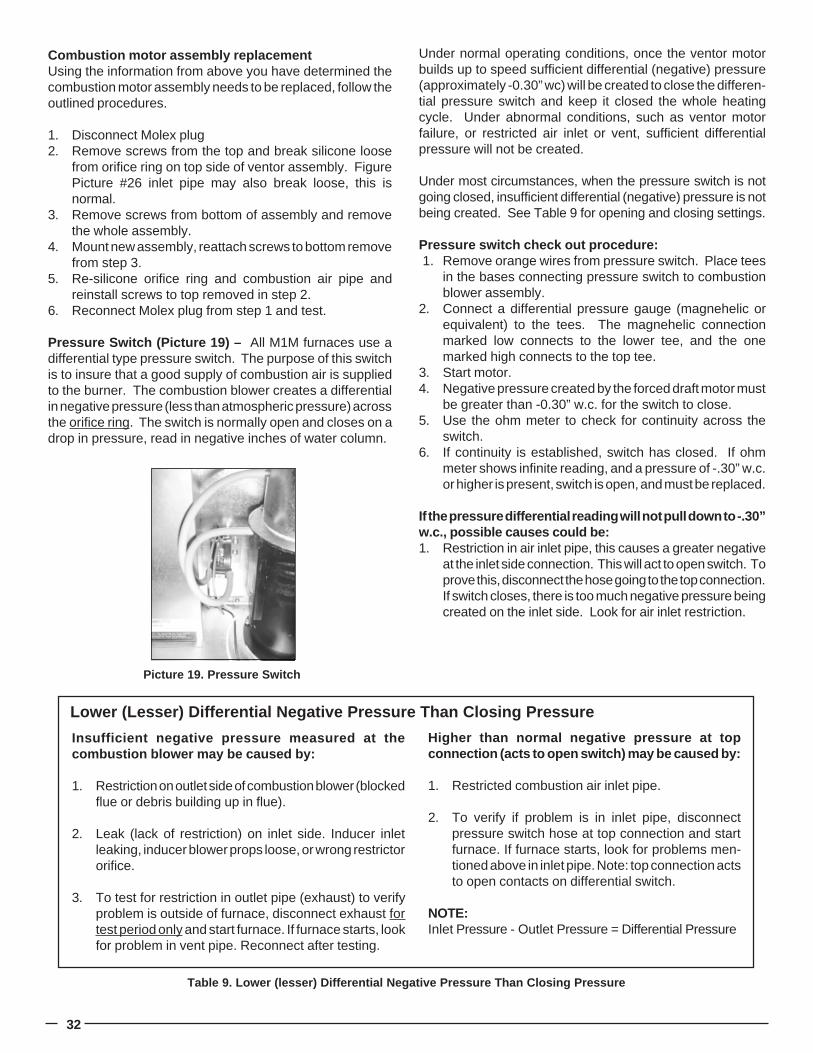
32
Combustion motor assembly replacementUsing the information from above you have determined thecombustion motor assembly needs to be replaced, follow theoutlined procedures.
1. Disconnect Molex plug2. Remove screws from the top and break silicone loose
from orifice ring on top side of ventor assembly. FigurePicture #26 inlet pipe may also break loose, this isnormal.
3. Remove screws from bottom of assembly and removethe whole assembly.
4. Mount new assembly, reattach screws to bottom removefrom step 3.
5. Re-silicone orifice ring and combustion air pipe andreinstall screws to top removed in step 2.
6. Reconnect Molex plug from step 1 and test.
Pressure Switch (Picture 19) – All M1M furnaces use adifferential type pressure switch. The purpose of this switchis to insure that a good supply of combustion air is suppliedto the burner. The combustion blower creates a differentialin negative pressure (less than atmospheric pressure) acrossthe orifice ring. The switch is normally open and closes on adrop in pressure, read in negative inches of water column.
Under normal operating conditions, once the ventor motorbuilds up to speed sufficient differential (negative) pressure(approximately -0.30” wc) will be created to close the differen-tial pressure switch and keep it closed the whole heatingcycle. Under abnormal conditions, such as ventor motorfailure, or restricted air inlet or vent, sufficient differentialpressure will not be created.
Under most circumstances, when the pressure switch is notgoing closed, insufficient differential (negative) pressure is notbeing created. See Table 9 for opening and closing settings.
Pressure switch check out procedure: 1. Remove orange wires from pressure switch. Place tees
in the bases connecting pressure switch to combustionblower assembly.
2. Connect a differential pressure gauge (magnehelic orequivalent) to the tees. The magnehelic connectionmarked low connects to the lower tee, and the onemarked high connects to the top tee.
3. Start motor.4. Negative pressure created by the forced draft motor must
be greater than -0.30” w.c. for the switch to close.5. Use the ohm meter to check for continuity across the
switch.6. If continuity is established, switch has closed. If ohm
meter shows infinite reading, and a pressure of -.30” w.c.or higher is present, switch is open, and must be replaced.
If the pressure differential reading will not pull down to -.30”w.c., possible causes could be:1. Restriction in air inlet pipe, this causes a greater negative
at the inlet side connection. This will act to open switch. Toprove this, disconnect the hose going to the top connection.If switch closes, there is too much negative pressure beingcreated on the inlet side. Look for air inlet restriction.
Table 9. Lower (lesser) Differential Negative Pressure Than Closing Pressure
Insufficient negative pressure measured at thecombustion blower may be caused by:
1. Restriction on outlet side of combustion blower (blockedflue or debris building up in flue).
2. Leak (lack of restriction) on inlet side. Inducer inletleaking, inducer blower props loose, or wrong restrictororifice.
3. To test for restriction in outlet pipe (exhaust) to verifyproblem is outside of furnace, disconnect exhaust fortest period only and start furnace. If furnace starts, lookfor problem in vent pipe. Reconnect after testing.
Higher than normal negative pressure at topconnection (acts to open switch) may be caused by:
1. Restricted combustion air inlet pipe.
2. To verify if problem is in inlet pipe, disconnectpressure switch hose at top connection and startfurnace. If furnace starts, look for problems men-tioned above in inlet pipe. Note: top connection actsto open contacts on differential switch.
NOTE:Inlet Pressure - Outlet Pressure = Differential Pressure
Lower (Lesser) Differential Negative Pressure Than Closing Pressure
Picture 19. Pressure Switch
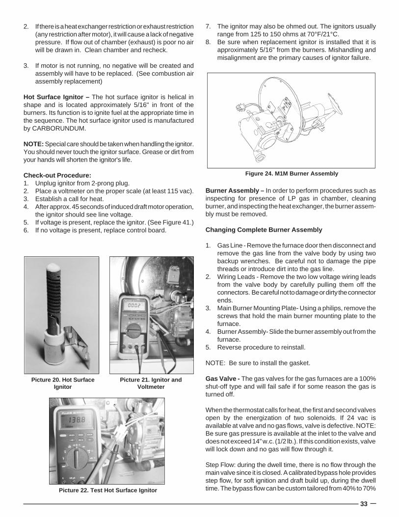
33
2. If there is a heat exchanger restriction or exhaust restriction(any restriction after motor), it will cause a lack of negativepressure. If flow out of chamber (exhaust) is poor no airwill be drawn in. Clean chamber and recheck.
3. If motor is not running, no negative will be created andassembly will have to be replaced. (See combustion airassembly replacement)
Hot Surface Ignitor – The hot surface ignitor is helical inshape and is located approximately 5/16" in front of theburners. Its function is to ignite fuel at the appropriate time inthe sequence. The hot surface ignitor used is manufacturedby CARBORUNDUM.
NOTE: Special care should be taken when handling the ignitor.You should never touch the ignitor surface. Grease or dirt fromyour hands will shorten the ignitor's life.
Check-out Procedure:1. Unplug ignitor from 2-prong plug.2. Place a voltmeter on the proper scale (at least 115 vac).3. Establish a call for heat.4. After approx. 45 seconds of induced draft motor operation,
the ignitor should see line voltage.5. If voltage is present, replace the ignitor. (See Figure 41.)6. If no voltage is present, replace control board.
7. The ignitor may also be ohmed out. The ignitors usuallyrange from 125 to 150 ohms at 70°F/21°C.
8. Be sure when replacement ignitor is installed that it isapproximately 5/16" from the burners. Mishandling andmisalignment are the primary causes of ignitor failure.
Picture 20. Hot SurfaceIgnitor
Picture 21. Ignitor andVoltmeter
Picture 22. Test Hot Surface Ignitor
Figure 24. M1M Burner Assembly
Burner Assembly – In order to perform procedures such asinspecting for presence of LP gas in chamber, cleaningburner, and inspecting the heat exchanger, the burner assem-bly must be removed.
Changing Complete Burner Assembly
1. Gas Line - Remove the furnace door then disconnect andremove the gas line from the valve body by using twobackup wrenches. Be careful not to damage the pipethreads or introduce dirt into the gas line.
2. Wiring Leads - Remove the two low voltage wiring leadsfrom the valve body by carefully pulling them off theconnectors. Be careful not to damage or dirty the connectorends.
3. Main Burner Mounting Plate- Using a philips, remove thescrews that hold the main burner mounting plate to thefurnace.
4. Burner Assembly- Slide the burner assembly out from thefurnace.
5. Reverse procedure to reinstall.
NOTE: Be sure to install the gasket.
Gas Valve - The gas valves for the gas furnaces are a 100%shut-off type and will fail safe if for some reason the gas isturned off.
When the thermostat calls for heat, the first and second valvesopen by the energization of two solenoids. If 24 vac isavailable at valve and no gas flows, valve is defective. NOTE:Be sure gas pressure is available at the inlet to the valve anddoes not exceed 14” w.c. (1/2 lb.). If this condition exists, valvewill lock down and no gas will flow through it.
Step Flow: during the dwell time, there is no flow through themain valve since it is closed. A calibrated bypass hole providesstep flow, for soft ignition and draft build up, during the dwelltime. The bypass flow can be custom tailored from 40% to 70%
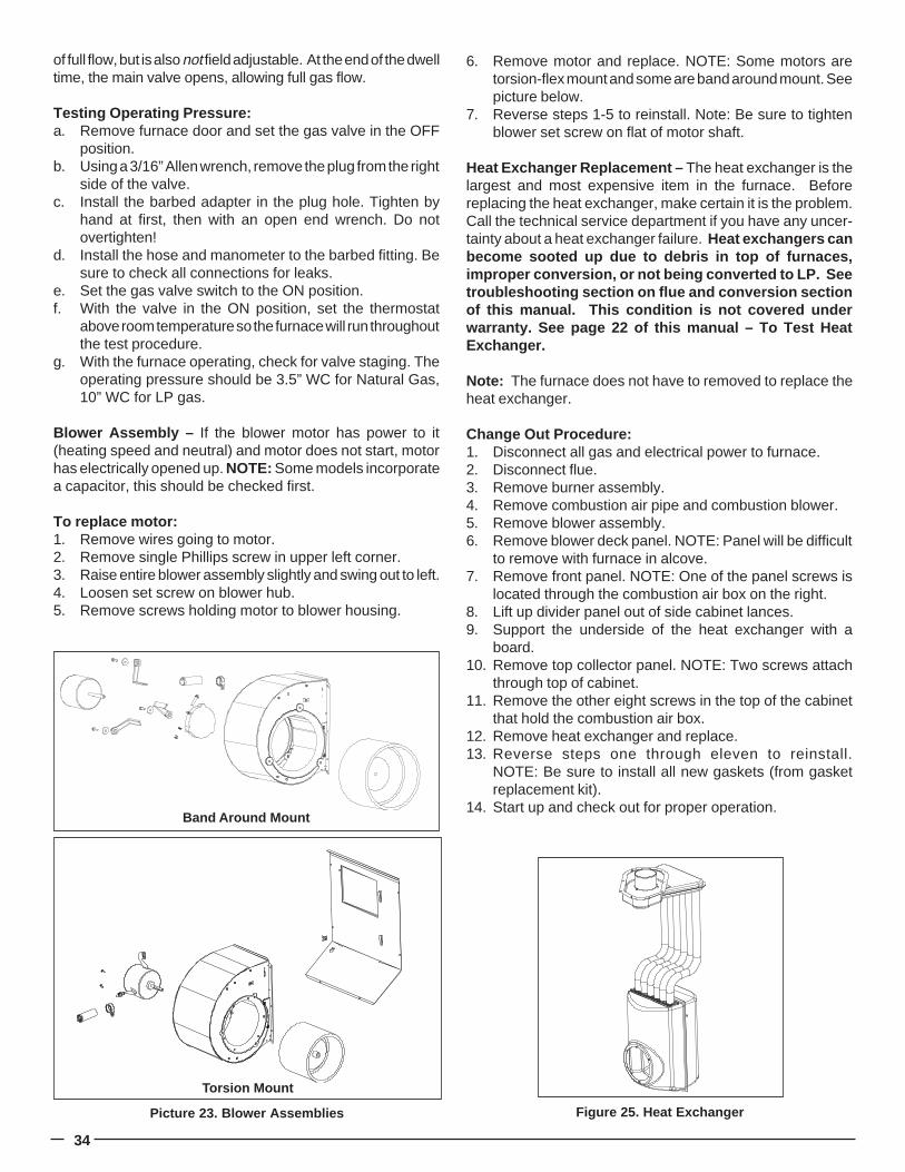
34
of full flow, but is also not field adjustable. At the end of the dwelltime, the main valve opens, allowing full gas flow.
Testing Operating Pressure:a. Remove furnace door and set the gas valve in the OFF
position.b. Using a 3/16” Allen wrench, remove the plug from the right
side of the valve.c. Install the barbed adapter in the plug hole. Tighten by
hand at first, then with an open end wrench. Do notovertighten!
d. Install the hose and manometer to the barbed fitting. Besure to check all connections for leaks.
e. Set the gas valve switch to the ON position.f. With the valve in the ON position, set the thermostat
above room temperature so the furnace will run throughoutthe test procedure.
g. With the furnace operating, check for valve staging. Theoperating pressure should be 3.5” WC for Natural Gas,10” WC for LP gas.
Blower Assembly – If the blower motor has power to it(heating speed and neutral) and motor does not start, motorhas electrically opened up. NOTE: Some models incorporatea capacitor, this should be checked first.
To replace motor:1. Remove wires going to motor.2. Remove single Phillips screw in upper left corner.3. Raise entire blower assembly slightly and swing out to left.4. Loosen set screw on blower hub.5. Remove screws holding motor to blower housing.
6. Remove motor and replace. NOTE: Some motors aretorsion-flex mount and some are band around mount. Seepicture below.
7. Reverse steps 1-5 to reinstall. Note: Be sure to tightenblower set screw on flat of motor shaft.
Heat Exchanger Replacement – The heat exchanger is thelargest and most expensive item in the furnace. Beforereplacing the heat exchanger, make certain it is the problem.Call the technical service department if you have any uncer-tainty about a heat exchanger failure. Heat exchangers canbecome sooted up due to debris in top of furnaces,improper conversion, or not being converted to LP. Seetroubleshooting section on flue and conversion sectionof this manual. This condition is not covered underwarranty. See page 22 of this manual – To Test HeatExchanger.
Note: The furnace does not have to removed to replace theheat exchanger.
Change Out Procedure:1. Disconnect all gas and electrical power to furnace.2. Disconnect flue.3. Remove burner assembly.4. Remove combustion air pipe and combustion blower.5. Remove blower assembly.6. Remove blower deck panel. NOTE: Panel will be difficult
to remove with furnace in alcove.7. Remove front panel. NOTE: One of the panel screws is
located through the combustion air box on the right.8. Lift up divider panel out of side cabinet lances.9. Support the underside of the heat exchanger with a
board.10. Remove top collector panel. NOTE: Two screws attach
through top of cabinet.11. Remove the other eight screws in the top of the cabinet
that hold the combustion air box.12. Remove heat exchanger and replace.13. Reverse steps one through eleven to reinstall.
NOTE: Be sure to install all new gaskets (from gasketreplacement kit).
14. Start up and check out for proper operation.
Picture 23. Blower Assemblies
Band Around Mount
Torsion Mount
Figure 25. Heat Exchanger
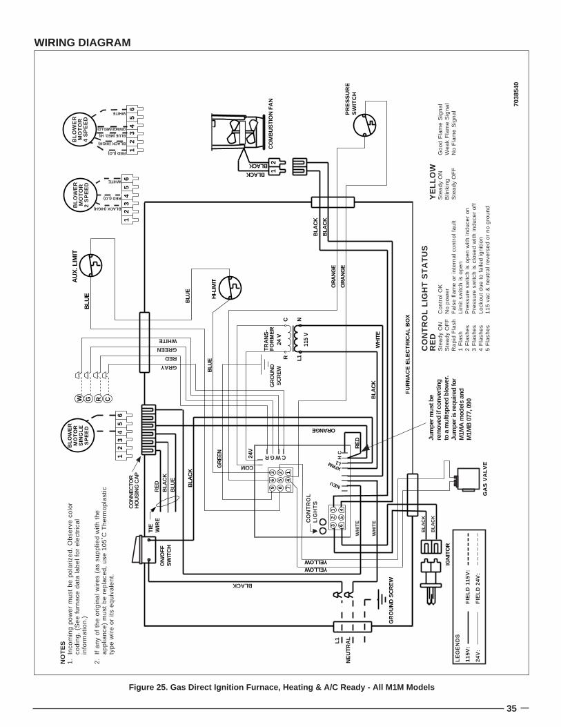
35
ORANGE
BL
OW
ER
MO
TO
RS
ING
LE
SP
EE
D
ON
/OFF
SW
ITC
H
CRGW
GA
S V
AL
VE
HI-L
IMITA
UX
. LIM
IT
TR
AN
S-
FO
RM
ER
PR
ES
SU
RE
S
WIT
CH
65
43
21
65
43
21 C
OM
BU
ST
ION
FA
N
L1NC
R24
V
115
V
21
1 452
63
123
456
789
IGN
ITO
R
BLU
E
BLU
EB
LAC
K
GR
EE
N
YELLOWYELLOW
BLA
CK
BLA
CK
OR
AN
GE
OR
AN
GE
BLA
CK
WH
ITE
L1
NE
UT
RA
L
GR
OU
ND
SC
RE
W
FU
RN
AC
E E
LEC
TR
ICA
L B
OX
24V
NEU
CH
L1XFRM
TIE
W
IRE
RE
DB
LAC
KB
LUE
CO
NN
EC
TOR
HO
US
ING
CA
P
GR
OU
ND
SC
RE
W
BLACK
BLACK
CO
NT
RO
L L
IGH
T S
TA
TU
SR
ED
YE
LL
OW
Ste
ad
y O
NC
on
tro
l O
KS
tea
dy
ON
Go
od
Fla
me
Sig
na
lS
tea
dy
OF
FN
o p
ow
er
Blin
kin
gW
ea
k F
lam
e S
ign
al
Ra
pid
Fla
shF
als
e f
lam
e o
r in
tern
al
con
tro
l fa
ult
Ste
ad
y O
FF
No
Fla
me
Sig
na
l1
Fla
shL
imit
sw
itch
is
op
en
2 F
lash
es
Pre
ssu
re s
wit
ch i
s o
pe
n w
ith
in
du
cer
on
3 F
lash
es
Pre
ssu
re s
wit
ch i
s cl
ose
d w
ith
in
du
cer
off
4 F
lash
es
Lo
cko
ut
du
e t
o f
aile
d i
gn
itio
n5
Fla
she
s1
15
va
c &
ne
utr
al
reve
rse
d o
r n
o g
rou
nd
CO
NT
RO
LL
IGH
TS
RE
D Jum
per m
ust b
e re
mov
ed if
con
verti
ng
to a
mul
tispe
ed b
low
er.
Jum
per i
s re
quire
d fo
r M
1MA
mod
els
and
M1M
B 0
77, 0
90
BLACK
WH
ITE
WH
ITE
BLA
CK
BLA
CK
GREEN
RED
GRAY
WHITE
BLACK (HIGH)
RED (LO)
WHITE
RED (LO)
BLACK (HIGH)
BLUE (MED. HI)
ORANGE (MED. LO)
WHITE
65
43
21
LE
GE
ND
S
11
5V
:F
IEL
D 1
15
V:
24
V:
FIE
LD
24
V:
BL
OW
ER
MO
TO
R2
SP
EE
D
BL
OW
ER
MO
TO
R4
SP
EE
D
NO
TE
S1
.In
com
ing
po
we
r m
ust
be
po
lari
zed
. O
bse
rve
co
lor
cod
ing
. (S
ee
fu
rna
ce d
ata
la
be
l fo
r e
lect
rica
l in
form
ati
on
.)
2.
If a
ny
of
the
ori
gin
al
wir
es
(as
sup
plie
d w
ith
th
e
ap
plia
nce
) m
ust
be
re
pla
ced
, u
se 1
05
˚C T
he
rmo
pla
stic
ty
pe
wir
e o
r it
s e
qu
iva
len
t.
SU
PP
LIE
DB
Y IN
STA
LLE
R
C W G R
COM
BLU
E
WIRING DIAGRAM
7038
540
Figure 25. Gas Direct Ignition Furnace, Heating & A/C Ready - All M1M Models
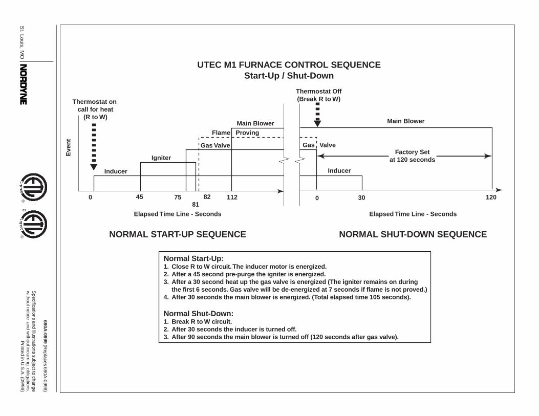
UTEC M1 FURNACE CONTROL SEQUENCEStart-Up / Shut-Down
Thermostat on call for heat
(R to W)
Eve
nt
Inducer
Igniter
Main BlowerFlame Proving
Gas Valve
Main Blower
Gas ValveFactory Set
at 120 seconds
Elapsed Time Line - Seconds
Thermostat Off(Break R to W)
Inducer
0 30 1200 4581
75 82 112
NORMAL START-UP SEQUENCE
Elapsed Time Line - Seconds
NORMAL SHUT-DOWN SEQUENCE
Normal Start-Up:1. Close R to W circuit. The inducer motor is energized.2. After a 45 second pre-purge the igniter is energized.3. After a 30 second heat up the gas valve is energized (The igniter remains on during
the first 6 seconds. Gas valve will be de-energized at 7 seconds if flame is not proved.)4. After 30 seconds the main blower is energized. (Total elapsed time 105 seconds).
Normal Shut-Down:1. Break R to W circuit.2. After 30 seconds the inducer is turned off.3. After 90 seconds the main blower is turned off (120 seconds after gas valve).
St. Louis, M
O
690A-0999 (R
eplaces 690A-0998)
Specifications and illustrations subject to change
without notice and w
ithout incurring obligations.P
rinted in U.S
.A. (09/99)
®®
C