
69-2490-05 - THX9321 Prestige® 2.0 THX9421 Prestige® IAQ 2.0 with EIM
28
THX9321 Prestige® 2.0 THX9421 Prestige® IAQ 2.0 with EIM With wireless accessories ® U.S. Registered Trademark. Copyright © 2012 Honeywell International Inc. All rights reserved. System Installation Guide Control for up to 4 Heat/2 Cool heat pump systems or up to 3 Heat/2 Cool conventional systems for residential and commercial applications. Installation guide for: Quick start guide • Prestige THX9321/9421 thermostat • Equipment Interface Module (EIM) • Portable Comfort Control • Wireless Outdoor Sensor • Wireless Indoor Sensor • RedLINK ™ Internet Gateway 1 Install thermostat .......................................................... page 3 2 Install optional Equipment Interface Module (EIM)................ 3 3 Power optional accessories ................................................... 4 4 Link thermostat to wireless network ...................................... 5 5 Link optional accessories to wireless network ...................... 6 6 Install optional sensors .......................................................... 7 7 Setup installer options ........................................................... 8 Wiring guides .................................................................. 10-17 Key features .................................................................... 18-25 Device replacement and specifications .......................... 26-27 DISCONNECT POWER BEFORE INSTALLATION. Can cause electrical shock or equipment damage. MERCURY NOTICE: If this product is replacing a control that contains mercury in a sealed tube, do not place the old control in the trash. Contact the Thermostat Recycling Corporation at www.thermostat-recycle.org or 800-238-8192 for information on how and where to properly and safely dispose of your old thermostat. Must be installed by a trained, experienced technician. Read these instructions carefully. Failure to follow these instructions can damage the product or cause a hazardous condition. 69-2490-05 TM
Transcript of 69-2490-05 - THX9321 Prestige® 2.0 THX9421 Prestige® IAQ 2.0 with EIM

THX9321 Prestige® 2.0 THX9421 Prestige® IAQ 2.0 with EIMWith wireless accessories
® U.S. Registered Trademark.Copyright © 2012 Honeywell International Inc.All rights reserved.
SystemInstallation Guide
Control for up to 4 Heat/2 Cool heat pump systems or up to 3 Heat/2 Cool conventional systems for residential and commercial applications.
Installation guide for:
Quick start guide
• PrestigeTHX9321/9421thermostat
• EquipmentInterfaceModule(EIM)
• PortableComfortControl
• WirelessOutdoorSensor
• WirelessIndoorSensor
• RedLINK™InternetGateway
1 Install thermostat ..........................................................page 32 Install optional Equipment Interface Module (EIM) ................33 Power optional accessories ...................................................44 Link thermostat to wireless network ......................................55 Link optional accessories to wireless network ......................66 Install optional sensors ..........................................................77 Setup installer options ...........................................................8
Wiring guides ..................................................................10-17
Key features ....................................................................18-25
Device replacement and specifications ..........................26-27
DISCONNECT POWER BEFORE INSTALLATION. Can cause electrical shock or equipment damage.
MERCURY NOTICE: If this product is replacing a control that contains mercury in a sealed tube, do not place the old control in the trash. Contact the Thermostat Recycling Corporation at www.thermostat-recycle.org or 800-238-8192 for information on how and where to properly and safely dispose of your old thermostat.
Must be installed by a trained, experienced technician. Read these instructions carefully. Failure to follow these instructions can damage the product or cause a hazardous condition.
69-2490-05
TM

System Installation Guide
269-2490—05
Your Honeywell advantage
RedLINK™ CompatibleIncreaseyourcontentandprofitperjobbyincludingRedLINK™accessoriesthatmeetyourcustomers'comfortandconvenienceneeds.RedLINKaccessoriesincludetheWirelessOutdoorSensor,PortableComfortControl(PCC),EquipmentInterfaceModule(EIM),RedLINKInternetGateway,WirelessIndoorSensor,TrueSTEAM™humidifierwithWirelessAdapter,TrueZONE™zoningpanelwithWirelessAdapter,VentBoostRemoteandEntry/ExitRemote.
Customizable Service RemindersSetupto10servicereminders.Choosefromthepre-setoptionsorcustomizeyourown.Remindersbasedondate,outdoortemperatureoradrycontactinputwillalertcustomerswithinstructionstocontactyouforassistance.
Delta T Alerts and DiagnosticsAlertsgivecustomersasenseofsecuritywhilealsoenablingyoutoserviceorreplacetheequipmentpriortoalossofheatingorcooling.Basedonlimitsyousetatinstallation,cus-tomerscanbealertedwhentheirsystemisnotoperatingasexpected.Thesystemalertwillinstructcustomerstocontactyouforassistance.RequiresEIM.
Delta T Installer TestSavetimebyviewingDeltaTwhilerunningasystemtesttoverifyproperoperation.RequiresEIM.
Universal Inputs – S1 and S2AssignableinputsallowyoutoconfigureIndoorandOutdoorTemperatureSensors,DischargeandReturnAirSensorsorDryContactDevices.DryContactDevicescanbeusedtotrippre-setorcustomizedalertsonthethermostathomescreen.RequiresEIM.
User Interactions LogTheinteractionlogstoreshistoryofthermostatsettingchangesincludingtemperature,sys-temandinstallersetup.Youcanusetheinteractionlogtosavetimebydeterminingiftheissue is a system error or an accidental user error.
Configurable for Residential and Light Commercial ApplicationsOnethermostatdoesitalltomeettheneedsofResidentialandLightCommercialapplica-tions.SimplyselectResidentialorCommercialduringtheinstallersetup.IfCommercialisselected,thethermostatwillusecommerciallanguage,meetbuildingcodesandoffer365dayholidayscheduling.
USB Port for Quick Installer SetupSavetimebyusingaUSBsticktouploadinstallersettingsandserviceremindersinonesimple step.
Selectable SensorsWhenpairedwithaWirelessIndoorSensor(s)youhavetheabilitytochoosewhichsensor(s)tousefortemperature,humidificationanddehumidification.Theycanbeusedincombinationfortemperatureaveraging—orindividually—toconditionhumiditylevelsinseparate spaces.

THX9321/9421 Prestige® IAQ and RF EIM
3 69-2490—05
MCR29241
MCR32386
Install thermostat1
• THX9421:MountthethermostatandwiretoCandRterminalsoftheEquipmentInterfaceModule(EIM),ortoaseparate24volttransformer(notprovided).
• THX9321:InstallandwireasaboveifusingEIM.Ifnot,seepages13-15.
Seepages10-17fordetailedwiringguidelines
MCR32387
MCR32389A
R
C
Y
Y2G
W O/B
W2
AUX1
W3
AUX2
A L/A
Strip 1/4” insulation, then insert wires as shown.
Install Equipment Interface Module (if used)2
[If no EIM is used, skip to Section 3.]
Usescrews&anchorsasappropriateforthemountingsurface.MounttheEIMneartheHVACequipment,orontheequipmentitself.
MCR32388
NOTE: If you install more than one thermostat and EIM, the EIMs must be at least 2 feet apart.
If you are installing discharge and return air sensors, refer to the mounting instructions in the Alerts and Delta T Diagnostics Installation Instructions packed with the Prestige IAQ 2.0 kit.
When the THX9321 thermostat is used with the EIM, the relays in the thermostat do not function.

System Installation Guide
469-2490—05
M32940
[If no wireless accessories are used, skip to Section 4.]
Portable Comfort Control
Install 2 fresh AAA alkaline batteries Install 3 fresh AA alkaline batteries
Wireless Outdoor Sensor Wireless Indoor Sensor
Install 2 fresh AA lithium batteries
Power optional accessories3
TheHoneywellRedLINKInternetGatewaygivesyourcustomersremoteaccesstohomeclimate-controlsystemsfromanylocationwithInternetaccess.
UsingaWebbrowser,userscanreviewandadjustindoortemperature, systemmodeandothersettings.TheGatewaycanalsosendalertstoasmanyas6emailaddressesifaproblemoccurs.
RedLINK™ Internet Gateway
Connect power cord to an electrical outlet not controlled by a wall switch
Connect RedLINK Gateway to a router or modem with Ethernet cable (RJ45).
MCR32937 MCR32938 MCR32939

THX9321/9421 Prestige® IAQ and RF EIM
5 69-2490—05
MCR32941
CONNECT
CONNECTED
S2S2S1S1
Link thermostat to the wireless network (ifusedwithanEIMorTrueZONEWirelessAdapter)
4
Next,linkallcomponentsandRedLINK™accessoriestothewirelessnetwork.
Initial powerup
Whenthethermostatisfirstactivated,itwillleadyouthroughthesteps necessarytodefineandsetupyoursystem.Thestepswillchangedependingonthetypeofsystemandthermostatyou'reinstalling.
Setup options for THX9321
If non-zoned system:• Setupforthermostatonly• SetupforusewithEIM
If zoned system:• SetupforEIMwiredtozonepanel• Setupforthermostatwiredtozonepanel• SetupforRedLINKwirelessconnectiontozonepanel
(using THM4000 TrueZONE Wireless Adapter)
Setup options for THX9421
If non-zoned system:• SetupforEIMconnection
If zoned system:• SetupforEIMwiredtozonepanel• SetupforRedLINKwirelessconnectiontozonepanel
(using THM4000 TrueZONE Wireless Adapter)
While the EIM light is flashing, press NEXT to link the thermostat with the EIM. After a brief delay, the screen will display "Device Connected."
Press and release the CONNECT button at the EIM or Wireless Adapter, and make sure the "Connected" light is flashing green.
If the "Connected" light does not flash, make sure no other RedLINK devices are in Wireless Setup mode, then try again.
Link thermostat to EIM or TrueZONE® Wireless Adapter
Usethestep-by-stepthermostatmenustodefineyoursystemtype(above).WhenyoureachtheWirelessSetupscreen,followthestepsbelow:
At any screen you can press HELP for more information, or press BACK to change earlier options.
If the power light at the wireless adapter does not turn on, consult the TrueZONE manual for help.
"Connected" status light• Green flashing: In Wireless Setup mode.• Green steady: RedLINK device(s) are communicating.• Red: RedLINK device(s) not communicating. Check EIM and RedLINK devices.

System Installation Guide
669-2490—05
MCR32943
MCR32942
CONNECT
WIRELESS SETUP
MCR32935MCR32934
WhiletheAddDevicescreenisdisplayedonthethermostat,press and release the CONNECTbuttononeachwirelessdevice,asdescribedbelow.Accessoriesneedtobeatleast2feetawayfromthethermostatorEIMduringthelinkingprocess.
MCR28847A
Link optional accessories to wireless network5
Wireless outdoor sensor
Portable Comfort Control
Wireless indoor sensor
Press and release CONNECT. After a short delay the thermostat will display "Wireless Outdoor Sensor added" on the Add Device screen.
Press and release CONNECT. After a short delay, the status light will glow green for 15 seconds.
If the status light turns red, the sensor did not link with the thermostat.
In normal operation, this light remains off. If it begins flashing red, batteries are low (power will be depleted after 2–3 weeks).
The linking procedure will time out if there is no keypress for 30 minutes. To begin again, press and hold in the lower right corner of the screen until the display changes (about 3 seconds).
Press DONE after all devices have been linked
Press CONNECT on the Portable Comfort Control display screen. Press DONE when the screen displays "Connected," then exit or continue to link another thermostat.
Error messages:E1 29 Incompatible device cannot be connected.E1 34 Low RF signal. Move device to a different location and try again.E1 38 Make sure the thermostat or the EIM is in Wireless Setup mode,
and the Portable Comfort Control is at least 2 feet away (600 mm).
RedLINK Internet GatewayPress and release the button on the bottom of the Internet Gateway. After a short delay, the RedLINK status light will glow steady green.
The Internet Gateway must be registered online before use at www.mytotalconnectcomfort.com. Enter the MAC ID and MAC CRC numbers located on the bottom of the Internet Gateway. For additional information, see instructions provided with the device.
If you need to return to the "Add Device" screen to add devices later, press MENU and scroll down to press INSTALLER OPTIONS. Enter the date code (password) when prompted. The date code is printed on the back of the thermostat; or press MENU > EQUIPMENT STATUS to find the date code. After you enter the password, scroll down to press WIRELESS DEVICE MANAGER and then select ADD DEVICE.
MCR32958A

THX9321/9421 Prestige® IAQ and RF EIM
7 69-2490—05
Install optional sensors
1 Mountthesensoronaverticalexteriorwall,atleast6inchesbelowanyoverhang.Choosealocationprotectedfromdirectsunlight.
2 Placesensorsecurelyinbracket,facingawayfromwall.
6
M28491
M28849A
[If no sensors are used, skip to Section 7.]
To install outdoor air sensor
To install indoor air sensor
1 Removethewallplateandmountit4to6feetabovetheflooronaninteriorwall.Drill3/16-inchholesfordrywall,7/32-inchforplaster.
2 Attachsensorsecurelytowallplateasshown.
M32936A
Setup Installer options (ISU)7
Tosetupthethermostat,pressMENUandscrolldowntopressINSTALLER OPTIONS. Enterthedatecode(password)whenprompted.Thedatecodeisprintedonthebackofthethermostat;orpressMENU > EQUIPMENT STATUS to find the date code. Afteryouenterthepassword,pressCREATE SETUP to setup the thermostat.
Abriefsummaryofinstalleroptionsfollows(pages8–9).Youcandownloadacomplete list of all options at http://customer.honeywell.com.
System Installation Guide
869-2490—05
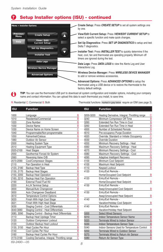
Setup Installer options (ISU) - continued7
TIP: You can use the thermostat USB port to download all system configuration and installer options, including your company name and contact information. You can upload this data to each thermostat you install, to save time.
1000 Language B1010 Residential/Commercial B1020 Zone Number B1030 Device Name B1030 Device Name on Home Screen C1040 Programmable/Non-programmable B1050 Fahrenheit/Celsius B1060 Outdoor Air Sensor B2000 Heating System Type B2010 Heating Equipment Type B2020-2100 Heat Stages B2050 Geothermal Forced Air System B2060 Reversing Valve O/B B2070-2090 Cool/Compressor Stages B2110 Fan Operation in Heat B2120, 2180 Backup Heat Type B2130, 2170 Backup Heat Stages B2150, 2200 Backup Heat Operation B2160, 2210 Backup Heat Fan Operation B2190 External Fossil Fuel Kit B2220 A-L/A Terminal Setup C3000 Manual/Auto Changeover B3000 Auto Changeover Deadband B3010 Temperature Control Options B3020 Finish With High Cool Stage B3021 Finish With High Heat Stage B3030 Staging Control - Cool Differentials B3040-3060 Staging Control - Heat Differentials B3080, 3090 Staging Control - Backup Heat Differentials B3110 Backup Heat Upstage Timer B3120 Outdoor Compressor Lockout B3120 Outdoor Backup Heat Lockout B3130, 3150 Heat Cycles Per Hour B3140 Cool Cycles Per Hour B3160 Backup Heat Cycles Per Hour B3170-3190 Cooling Derivative, Integral, Throttling range C
3200-3220 Heating Derivative, Integral, Throttling range C3240 Minimum Compressor Off Time B3260 Extended Fan Run Time in Cool B3260 Extended Fan Run Time in Heat B4000 Number of Scheduled Periods B4010 Pre-occupancy Purge Duration C4020 Override: Standard or Initiate Occupancy C4030 Override Duration C4050 Minimum Recovery Settings - Heat C4060 Maximum Recovery Settings - Heat C4070 Minimum Recovery Settings - Cool C4080 Maximum Recovery Settings - Cool C4090 Adaptive Intelligent Recovery R4100 Minimum Cool Setpoint B4100 Maximum Heat Setpoint B4110 Keypad Lockout B4120 Entry/Exit Remote -
Home/Occupied Cool Setpoint B4120 Entry/Exit Remote -
Home/Occupied Heat Setpoint B4130 Entry/Exit Remote -
Away/Unoccupied Cool Setpoint B4130 Entry/Exit Remote -
Away/Unoccupied Heat Setpoint B4140 Entry/Exit Remote -
Vacation/Holiday Cool Setpoint B4140 Entry/Exit Remote -
Vacation/Holiday Heat Setpoint B5000 Select Wired Sensors B5010 Indoor Temperature Sensor Name B5020 Terminals Wired to Indoor Sensor B5030 Indoor Temperature Sensor Type B5040 Indoor Sensors Used for Temperature Control B5050 Terminals Wired to Outdoor Sensor B5070 Terminals Wired to Return Air Sensor B5080 Return Air Sensor Type B
ISU Function ISU Function
Thermostat functions marked in gray below require an EIM (see page 3).R: Residential C: Commercial B: Both
Create Setup: Press CREATE SETUP to set all system settings one by one.
View/Edit Current Setup: Press VIEW/EDIT CURRENT SETUP to select a specific function and make quick changes.
Set Up Diagnostics: Press SET UP DIAGNOSTICS to setup and test Delta T diagnostics.
Installer Test: Press INSTALLER TEST to quickly determine if the heat, cool, fan and thermostat are operating properly. Minimum off timers are ignored during the test.
Data Logs: Press DATA LOGS to view the Alerts Log and User Interactions Log.
Wireless Device Manager: Press WIRELESS DEVICE MANAGER to add or remove wireless accessories.
Advanced Options: Press ADVANCED OPTIONS to setup the thermostat using a USB device or to restore the thermostat to the factory default settings.

THX9321/9421 Prestige® IAQ and RF EIM
9 69-2490—05
5090 Terminals Wired to Discharge Air Sensor B5100 Discharge Air Sensor Type B5110 A-Coil Low Temperature Cutoff B6000 Select the Dry Contacts in the System B6010 Terminals Wired to Remote Setback Dry Contact C6020 Remote Setback Dry Contact Setup C6030 Remote Setback Time Delay C6040 Remote Setback - Standby Cool Setpoint C6040 Remote Setback - Standby Heat Setpoint C6050 Terminals Wired to Full Drain Pan Alert
Dry Contact B6060 Full Drain Pan Alert Dry Contact Setup B6070 Terminals Wired to Dirty Filter Alert Dry Contact B6080 Dirty Filter Alert Dry Contact Setup B6090 Terminals Wired to Water Leak Alert Dry Contact B6100 Water Leak Alert Dry Contact Setup B6110 Terminals Wired to System Shutdown
Alert Dry Contact B6120 System Shutdown Alert Dry Contact Setup B6130 Terminals Wired to Service Needed
Alert Dry Contact B6140 Service Needed Alert Dry Contact Setup B6150 Terminals Wired to Fan Failure Alert Dry Contact B6160 Fan Failure Alert Dry Contact Setup B6170 Terminals Wired to Custom Alert Dry Contact B6180 Custom Alert Dry Contact Setup B6190, 6200 Custom Alert Name and Message B7000 Filter Type B7020 Number of Air Filters B7110 Air Filter Replacement Reminder B7110 Air Filter 2 Replacement Reminder B7120 EAC Cell Cleaning Reminder B7120 EAC Pre-Filter Cleaning Reminder B7120 EAC Post-Filter Replacement Reminder B8000 Humidifier Type B8010 Indoor Sensor Used for Humidification Control B8030 Terminals Wired to the Humidifier B8050 Humidification - Window Protection B8060 System Modes Allowing Humidification B8070 Humidification Control B8080 Humidifier Lockout B8100 Clean Tank / Water Filter Replacement Reminder B8100 Humidifier Pad Replacement Reminder B9000 Dehumidification Equipment B9010 Indoor Sensor Used for Dehumidification Control B9020 Humidity Sensor Displayed on the Home Screen B9040 Terminals Wired to Dehumidification Equipment B9050 A/C with Low Speed Fan Setup B9050 Hot Gas Bypass Setup C9070 Dehumidification - Overcooling Limit R9080 Dehumidification Control C9090 Dehumidification Minimum On Time C9100 High Humidity Comfort Reset Setting C
9120 System Modes Allowing Dehumidification B9130 Dehumidifier Fan Control B9140 Dehumidifier Lockout B9180 Dehumidification Away Mode B9190 Dehumidification Away Mode - Fan Control B9200 Dehumidification Away Mode -
Low Limit Temperature B9200 Dehumidification Away Mode -
Temperature Setting B9200 Dehumidification Away Mode -
Dehumidification Setting B9210 Dehumidifier Filter Replacement Reminder B10000 Ventilation Type B10020 Terminals Wired to Ventilator/Fresh Air Damper B10050 Ventilation Control Method B10060 Ventilation Fan Control B10090 Number of Bedrooms R10090 Size of House R10100 Enter Equipment Ventilation Rate R10120 Ventilation Percent On Time B10125 Ventilation Priority R10130 Ventilation Low Temperature Lockout B10130 Ventilation High Temperature Lockout B10130 Ventilation High Dewpoint Lockout B10140 Lockout Ventilation on Hum/Dehum Calls B10160 Ventilate on High Indoor Humidity B10170 Ventilator Core Cleaning Reminder B10170 Ventilator Filter Cleaning Reminder B11000 Number of UV Devices B11050 UV Bulb Replacement Reminder B11050 UV Bulb 2 Replacement Reminder B12000 Installer Custom Reminders B13000 Heat Delta T Diagnostics B13010 Cool Delta T Diagnostics B13015 Set Advanced Delta T Diagnostic Options B13020 Allow Delta T Diagnostics During Humidification B13030 Allow Delta T Diagnostics During
Dehumidification B13040 Allow Delta T Diagnostics During Ventilation B13050-13080 Allow Heat Delta T Diagnostics:
Temp & Humidity B13090-13120 Allow Backup Heat Delta T Diagnostics:
Temp & Humidity B13130-13160 Allow Cool Delta T Diagnostics:
Temp & Humidity B13170 Defrost Cycle B13180 Delta T Alert Sensitivity B13190 Display Delta T Alerts to User B14000 Clock Format B14010 Daylight Saving Time B14020 Indoor Temperature Display Offset B14020 Indoor Humidity Display Offset B15000-15020 Dealer name, phone, email, website, message B
Installer options (ISU) - continued7
Thermostat functions marked in gray below require an EIM (see page 3).
ISU Function ISU Function

System Installation Guide
1069-2490—05
Typicalwiringofaconventionalsystemwithupto3-stageheatand2-stagecoolwithonetransformer.
EIM wiring guide — conventional systems
See following pages for additional thermostat wiring guidelines for heat pumps, geothermal systems and optional Economizer.
1
2
3
4
See guides on following pages for thermostat wiring and geothermal radiant heat wiring.
Wire a maximum of 2 sensors using the S1 and S2 terminals. See ISU 5000-6190 for options. S1 and S2 terminals can be connected to an indoor sensor, outdoor sensor, discharge sensor, return sensor, dry contact device to display an alert or an occupancy sensor for remote setback.
Remove jumper(s) if using separate transformers.
See Economizer wiring section.
HEAT STAGE 1
HEAT STAGE 2
HEAT STAGE 3
FAN
TO THERMOSTAT
STATUSLEDS
JUMPERS
SENSORS
CONV
FURNACE
R
C
WW2W3
G
Y2
Y
TRANSFORMER
120VAC
24VAC
COMPRESSORSTAGE 1
COMPRESSORSTAGE 2
POWERHEATCOOL
FANU1U2U3 A
CONNECT OPTIONALSENSORS TO
S1 AND S2 TERMINALS
(MAX. 2 SENSORS)
EIM
1
3
2
4
MCR32945A

THX9321/9421 Prestige® IAQ and RF EIM
11 69-2490—05
EIM wiring guide — heat pump systems
Typicalwiringofaheatpumpsystemwithuptofour-stageheatandtwo-stagecoolwithonetransformer.
1
2
3
See guides on following pages for thermostat wiring and geothermal radiant heat wiring.
Wire a maximum of 2 sensors using the S1 and S2 terminals. See ISU 5000-6190 for options. S1 and S2 terminals can be connected to an indoor sensor, outdoor sensor, discharge sensor, return sensor, dry contact device to display an alert or an occupancy sensor for remote setback.
L/A terminal sends continuous output when thermostat is set to EM HEAT mode, except when set up for Economizer or TOD. See Economizer wiring section.
CHANGEOVER VALVE
BACKUP HEAT STAGE 1
FAN RELAY
SENSORS
TO THERMOSTAT
HEAT PUMP
AIR HANDLERTRANSFORMER
120VAC
24VAC
COMPRESSORSTAGE 1
COMPRESSORSTAGE 2
O/BAUX1AUX2
O/B
BACKUP HEAT STAGE 2
COMPRESSOR MONITOR OR ZONE PANEL
RC
AUX1
AUX2
G
L/A
Y2
Y
POWERHEATCOOL
FANU1U2U3
STATUSLEDS
JUMPERS
L/A
3
3
1
2
EIM
CONNECT OPTIONALSENSORS TO
S1 AND S2 TERMINALS
(MAX. 2 SENSORS)
2 MCR32946A

System Installation Guide
1269-2490—05
EIM wiring guide — geothermal radiant heat
Typicalwiringforgeothermalradiantheat,geothermalforced-air,andbackupheatwithonetransformer.Seepage19foroperation.
1
2
3
U1, U2 or U3 terminals must be used for geothermal radiant heat (ISU 2010). Thermostat allows 2 stages of radiant heat—geothermal (stage 1) and boiler (stage 2).
“U” terminals are normally open dry contacts when set up for geothermal radiant heat. You must install a field jumper if radiant heat is powered by system transformer. Do NOT install a field jumper if radiant heat has its own transformer.
L/A terminal sends continuous output when thermostat is set to EM HEAT mode except when set up for Economizer or TOD. See Economizer wiring section.
O/BAUX1AUX2
O/B
RC
AUX1
AUX2
G
L
Y2
Y
L/A
CHANGEOVER VALVE
BACKUP HEAT STAGE 1
FAN RELAY
120VAC
24VAC
COMPRESSORSTAGE 1
COMPRESSORSTAGE 2
BACKUP HEAT STAGE 2
COMPRESSOR MONITOROR ZONE PANEL
GEOTHERMAL RADIANTHEAT STAGE 1
3
3
2
1
SENSORS
AIR HANDLERTRANSFORMER
STATUSLEDS
JUMPERS
OPTIONALJUMPER
POWERHEATCOOL
FANU1U2U3
TO THERMOSTAT
HEAT PUMP
EIM
2CONNECT OPTIONAL
SENSORS TOS1 AND S2 TERMINALS
(MAX. 2 SENSORS)
MCR32947A

THX9321/9421 Prestige® IAQ and RF EIM
13 69-2490—05
Thermostat wiring guides — Prestige THX9321
Typicalwiringofa2-heat/2-coolcon-ventionalsystemwithonetransformer
Typicalwiringofa3-heat/2-coolheatpumpsystemwithonetransformer
Typicalwiringforgeothermalradi-antheat,geothermalforced-airandbackupheatwithonetransformer.Seepage19foroperation.
Typicalwiringofa3-heat/2-coolheatpumpsystemwithtwotransformers(example-oilforcedairbackupheat)
1
2
3
4
5
6
U1 and U2 terminals are dry contacts.
L/A terminal sends continuous output when thermostat is set to EM HEAT mode except when set up for Economizer or TOD. See Economizer wiring section.
U1 or U2 terminals must be used for geothermal radiant heat (ISU 2010). Thermostat allows 2 stages of radiant heat—geothermal (stage 1) and boiler (stage 2).
"U" terminals are normally open dry contacts when set up for geothermal radiant heat. You must install a field jumper if radiant heat is powered by system transformer. Do NOT install a field jumper if radiant heat has its own transformer.
Remove jumper if using separate transformers.
Connect the THP9045 Wiresaver Module to the K terminal in heating/cooling applications that do not have a common wire at the thermostat. The K terminal cannot be used in heat-only applications. See THP9045 installation instructions for more information.
CHANGEOVER VALVE
BACKUP HEAT
COMPRESSOR STAGE 1
COMPRESSOR STAGE 2
FAN RELAY
COMPRESSOR MONITOROR ZONE PANEL
120VAC
O/B
AUX/E
Y
Y2
G
L/A
K
C
Rc
R
U1
U1
U2
U2
24VAC
Transformer
Thermostat
CR
1
26
MCR32948B
HEAT STAGE 1
HEAT STAGE 2
COMPRESSOR STAGE 1
COMPRESSOR STAGE 2
FAN RELAY
120VAC
W
W2
Y
Y2
G
A
K
C
Rc
R
U1
U1
U2
U2
24VAC
Transformer
Thermostat
CR
1
5
6MCR32949A
31
CHANGEOVER VALVE
COMPRESSOR STAGE 1
COMPRESSOR STAGE 2
FAN RELAY
COMPRESSOR MONITOROR ZONE PANEL
120VAC
O/B
AUX/E
Y
Y2
G
L/A
K
C
Rc
R
U1
U1
U2
U2
24VAC
Air HandlerTransformer
120VAC
24VAC
Backup HeatTransformer
CR
RC
Thermostat
BACKUP HEAT
1
26
MCR32950A
CHANGEOVER VALVE
BACKUP HEAT
COMPRESSOR STAGE 1
COMPRESSOR STAGE 2
FAN RELAY
COMPRESSOR MONITOROR ZONE PANEL
120VAC
O/B
AUX/E
Y
Y2
G
L/A
K
C
Rc
R
U1
U1
U2
U2
24VAC
Transformer
Thermostat
CR
GEOTHERMAL RADIANT
HEAT STAGE 1
32
4
6MCR32951A

System Installation Guide
1469-2490—05
Prestige THX9321 or EIM: Using universal relays to control heating or cooling
Poweringuniversalrelaywithseparateheatingtransformer(THX9321shown)
Poweringuniversalrelaywithsystemtransformer(THX9321shown)
1
2
3
U1/U2/U3 terminals are normally open dry contacts when set up for a stage of heating or cooling.
You must install a field jumper if the stage of heating or cooling is powered by system transformer. Do NOT install a field jumper if the stage of heating has its own transformer.
U1/U2/U3 terminals are assigned to a stage of heating or cooling in the Installer Setup. Options are:
THX9321 Thermostat (U1 and U2)• CoolStage3(ISU2080-commercialonly)• CoolStage4(ISU2090-commercialonly)• ConventionalHeatStage3(ISU2100,2140)• BackupHeatStage2forHeatPumps(ISU2170)• GeothermalRadiantHeat(seewiringguideonpages12-13)
THX9421 Thermostat with EIM (U1, U2 and U3)• CoolStage3(ISU2080-commercialonly)• CoolStage4(ISU2090-commercialonly)• GeothermalRadiantHeat(seewiringguideonpages12-13)
HEAT STAGE 3 orCOOL STAGE 3 or
COOL STAGE 4
120VAC
C
Rc
R
U1
U1
U2
U2
24VAC
Transformer
Thermostat
CR
1
1
23
MCR32952A
HEAT STAGE 3
120VAC
C
Rc
R
U1
U1
U2
U2
24VAC
Transformer
120VAC
24VAC
Transformer
Thermostat
CR
CR
1
1
2
3
MCR32953
Dry Contact Alerts
IfyouarenotusingtheS1andS2terminalsontheEIM,youcancon-nect them to a dry contact device to displayanalert.DrycontactalertsincludeFullDrainPan,DirtyFilter,WaterLeak,SystemShutdown,ServiceNeeded,FanFailureandCustomAlert(ISU6000).
You can connect multiple Dry Contact devices in parallel to the S1 or S2 terminals.
The dry contact device must be rated for low voltage.
EQUIPMENT DAMAGE HAZARD. Do not apply power to S1 or S2 terminals.
MULTIPLE DRY CONTACT DEVICES ON ONE SET OF TERMINALS
EIM
M31488
ONE DRY CONTACT DEVICE

THX9321/9421 Prestige® IAQ and RF EIM
15 69-2490—05
Wiring guide — IAQ equipment (EIM or thermostat)
"U"terminalscanbeusedforhumidification,dehumidificationorventilation. With power supply Without power supply
Typical hookup of non-powered humidifier.Typical hookup of powered humidifier.
Typical hookup of non-powered ventilation.
Typical hookup of variable speed blower for dehumidification in low speed.
Typical hookup of powered ventilation.
Typical hookup of powered dehumidifier (whole house dehumidifier).
POWEREDHUMIDIFIER
RH
RC
R
C
U3
U3U2
U2U1 U1
M32393
24VAC
120VAC
24VAC
120VAC24
VAC
FIELD INSTALLED JUMPER BETWEEN R AND U1
RH
RC
R
C24 VAC
U3
U3U2
U2U1 U1
NON-POWEREDHUMIDIFIER
M32394
24VAC
120VAC
POWEREDVENTILATOR
RH
RC
R
C24
VAC
U3
U3U2
U2
U1 U1
M32396
24VAC
120VAC
24VAC
120VAC
FIELD INSTALLED JUMPER BETWEEN R AND U1
RH
RC
R
C24 VAC
U3
U3U2
U2U1 U1
NON-POWEREDVENTILATOR
M32397
24VAC
120VAC
POWEREDDEHUMIDIFIER
RH
RC
R
C
U3
U3U2
U2U1 U1
M32398
24VAC
120VAC
24VAC
120VAC24
VAC
FIELD INSTALLED JUMPER BETWEEN R AND U1
RH
RC
R
C24 VAC
U3
U3U2
U2U1 U1
ORDEHUMIDIFICATION
WITH LOW SPEED FAN
M32392
24VAC
120VAC
1
2
KEY
= NORMALLY OPEN, DRY CONTACTS
ANY COMBINATION OF UNIVERSAL RELAYS (U1, U2, U3) CAN BE USED. THEY ARE SET IN THE THERMOSTAT INSTALLER SETUP.
= NORMALLY CLOSED, DRY CONTACTS
1
WIRE THE THERMOSTAT OR EIM UNIVERSAL RELAY TO THE LOW SPEED FAN FOR DEHUMIDIFICATION CONTROL AT THE EQUIPMENT. THE THERMOSTAT OR EIM RELAY CAN BE SET TO NORMALLY OPEN OR NORMALLY CLOSED IN THE THERMOSTAT INSTALLER SETUP.
2
M32954

System Installation Guide
1669-2490—05
Economizer Module wiring guides
TypicalwiringofaW7220EconomizerModuleforaheatpumpsystem,usingaPrestigeTHX9321thermostatorEquipmentInterfaceModule.
TypicalwiringofaW7220EconomizerModuleforaconventionalsystem,usingaPrestigeTHX9321thermostatorEquipmentInterfaceModule.
1
2
“A” or “L/A” terminal must be configured for Economizer in the installer setup (ISU 2220). These terminals are powered by the cooling transformer (Rc terminal).
Terminal AUX 2 is present only on the Equipment Interface Module.
120VAC
N Y1 Y2 W1 W2 G
24VAC
SD-O/B
OCC
E-GND
AUX
Y2I
Y2O
Y1I
Y1O
C
R
Rooftop Unit
Transformer
A Y Y2 W W2 G
Thermostat/EIMR
C
W7220 Economizer Module(See wiring guidelines provided with the product)
1
MCR32955A
120VAC
O/B N Y1 Y2 AUX AUX 2 G
24VAC
SD-O/B
OCC
E-GND
AUX
Y2I
Y2O
Y1I
Y1O
C
R
Rooftop Unit
Transformer
O/B L/A Y Y2 AUX AUX 2 G
Thermostat/EIMR
C
W7220 Economizer Module(See wiring guidelines provided with the product)
21
MCR32959A

THX9321/9421 Prestige® IAQ and RF EIM
17 69-2490—05
Economizer Module wiring guides
TypicalwiringofaW7213/W7214EconomizerModuleforaheatpumpsystem,usingaPrestigeTHX9321thermostatorEquipmentInterfaceModule.
TypicalwiringofaW7212EconomizerModuleforaconventionalheatingsystem,usingaPrestigeTHX9321thermostatorEquipmentInterfaceModule.
1
2
“A” or “L/A” terminal must be configured for Economizer in the installer setup (ISU 2220). These terminals are powered by the cooling transformer (Rc terminal).
Terminal AUX 2 is present only on the Equipment Interface Module.
120VAC
O/B N Y1 Y2 AUX AUX 2 G
24VAC
O or B
N
3
4
1
2 & 5
TR1
TR
Rooftop Unit
Transformer
O/B L/A Y Y2 AUX AUX 2 G
Thermostat/EIMR
C
W7213/W7214 Economizer Module(See wiring guidelines provided with the product)
21
MCR32956A
120VAC
N Y1 Y2 W1 W2 G
24VAC
N
3
4
1
2 & 5
TR1
TR
Rooftop Unit
Transformer
A Y Y2 W W2 G
Thermostat/EIMR
C
W7212 Economizer Module(See wiring guidelines provided with the product)
1
MCR32957A

System Installation Guide
1869-2490—05
TheEconomizercangreatlyreduceenergycostsifconfiguredproperly.Insomeclimatesthecoolingsystemmayrunhundredsofhours,whenitmaynotberequiredtomaintainindoorcomfort.Insomeconditions,ventilationwithoutdooraircanachievethesamelevelofcomfortatlowercost.TablesbelowexplainhowtheEconomizerfeaturemaintainscomfortwhileminimizingcosts.
Occupied Heat/Cool/Fan running
ON
Occupied temporarily Heat/Cool/Fan running
Occupied Heat/Cool/Fan NOT running
Occupied temporarily Heat/Cool/Fan NOT running
Pre-occupancy purge Fan running
Unoccupied Cooling system running
Unoccupied temporarily Cooling system running
Standby Cooling system running
Unoccupied Cooling system NOT runningOFF
Unoccupied temporarily Cooling system NOT running
Standby Cooling system NOT runningON
Non-programmable Fan running
Non-programmable Fan NOT running OFF
Occupied
ONOccupied temporarily
Temperature overrides
Unoccupied
OFFUnoccupied temporarily
Standby
Non-programmable
Economizer and TOD operation (ISU 2220) Commercial use only
Thermostat Mode
Thermostat Mode
Equipment OperationA-L/A terminal:
Economizer
A-L/A terminal: TOD

THX9321/9421 Prestige® IAQ and RF EIM
19 69-2490—05
The thermostat can be setup to control Geothermal Radiant Heat, Geothermal Forced Air Heat and Backup Heat, all from one thermostat. The thermostat stages the equipment starting with the Geothermal Radiant Heat followed by Geothermal Forced Air Heat and then Backup Heat as needed to maintain the desired temperature. The thermostat allows you to set differential temperature settings between each stage if you want the equipment to stage a certain way (see ISU 3030 to ISU 3090).
When the Backup Heat is fossil fuel, the Geothermal Forced Air Heat turns off when the Backup Heat turns on. Geothermal Radiant Heat stays on when the fossil fuel Backup Heat turns on.
When the Backup Heat is electric, Geothermal Radiant Heat and Geothermal Forced Air Heat stay on when the electric Backup Heat turns on.
Heat pump with outdoor temperature lockouts
Heat pump and backup heat operation
Geothermal Radiant Heat
Outdoortemperaturelockoutsareoptional.SeeInstallerSetup options(ISU3120).
Heat pump only
Heat pump with backup heat as needed *
Backup heat only
Heat pump only
Heat pump or backup heat operates *
Backup heat only
Ou
tdo
or
tem
per
atu
reO
utd
oo
r te
mp
erat
ure
Backup heat lockout
Backup heat lockout
Compressor lockout
Compressor lockout
* No backup heat unless indoor temperature drops to selected Backup Heat Differential setting, or Backup Heat Upstage Timer expires. Heat pump stays ON when backup heat turns on.
* No backup heat unless indoor temperature drops to selected Backup Heat Differential setting, or Backup Heat Upstage Timer expires. Heat pump turns OFF when backup heat turns on.
Backup heat allowed to run with heat pump (see table below)
Backup heat NOT allowed to run with heat pump (see table below)
Electric forced air Allowed to run with heat pump Thermostat controls fan
Gas or oil forced air NOT allowed to run with heat pump Equipment controls fan
Hot water radiant heat Allowed to run with heat pump [n/a]
Hot water fan coil Selectable in installer setup Thermostat controls fan
Other Selectable in installer setup Selectable in installer setup
Backup Heat Type Backup Heat Operation Backup Heat Fan Operation
To turn off Radiant Heat during the shoulder seasons, install an outdoor reset control and connect to the Radiant Heat or switch the thermostat to Emergency Heat mode.

System Installation Guide
2069-2490—05
Backup heat differential and upstage timer
Basic and Advanced Temperature Control Options (ISU 3010)
Abackupheatdifferentialandbackupheatupstagetimercanbesetonanysystemthathasmorethanonetypeofheatingequipment.Seeinstallersetupoptions(ISU3070-3110).
Normal operationWhentheBackup Heat DifferentialissettoComfort,thethermostatusesbackupheatasneededtokeeptheindoortemperaturewithin1°F(0.5°C)oftheset-point.
WhentheBackup Heat Differentialissetto2°Forhigher,backupheatisnotused unless the indoor temperature drops to the Backup Heat Differentialsettingor the Backup Heat Upstage Timerexpires,whicheveroccursfirst.Theupstagetimerstartswhenthehigheststageofthepreviousequipmenttypeturnson.
Manual temperature changeWhentheBackup Heat DifferentialissettoComfort,thethermostatusesbackupheatasneededtokeeptheindoortemperaturewithin1°F(0.5°C)oftheset-point.
WhentheBackup Heat Differentialissetto2°Forhigher,iftheprimaryheatismakingprogressasexpected,backupheatwillnotbeusedtoreachthenewsetpoint.Settoahighernumbertouselessbackupheat(agreaterdifferencebetweenthecurrentindoortemperatureandthenewsetpointisrequiredtoturnonbackupheat).Seenotesbelow.
Programmed recoveryIftheprimaryheatismakingprogressasexpected,backupheatwillnotbeusedtoreachthesetpointofthenextprogramperiod.Backupheatisalways restrict-edduringaprogrammedrecoverywhentheAdaptiveIntelligentRecoveryfeatureisused.Seenotebelow.
Basic Options:TheInstallerSetupdisplaysbasictemperaturecontroloptionswhichincludeBackupHeatDifferential,BackupHeatUpstageTimerandOutdoorTemperatureLockouts.Note:OutdoorTemperatureLockoutsonlyapplytoHeatPumpapplications.
Advanced Options:TheInstallerSetupdisplaysbothBasicandAdvancedOptions.AdvancedtemperaturecontroloptionsincludeFinishWithHighCoolStage,FinishWithHighHeatStage,TemperatureDifferentialsettingsbetweenallstagesandCycleRatesettingsperstage.
During a programmed recovery (or when the temperature setpoint is changed by the user), the thermostat waits to turn on the backup heat depending on system performance, load conditions and how many degrees the temperature setpoint is changed. Backup heat will be used ONLY when the temperature is not rising quickly enough to reach the setpoint in a reasonable time.
If the backup heat was used in the last 2 hours because the primary heat was not able to maintain the setpoint, the thermostat may turn on the backup heat earlier when the user raises the setpoint. This does NOT apply to heat pumps with fossil fuel backup heat.
Finish With High Heat or Cool Stage - When a multi-stage heating or cooling system is used, this feature keeps the high stage of the heating or cooling equipment running until the desired setpoint is reached. Recommended setting for Geothermal Heat Pumps to allow the loop to rest.

THX9321/9421 Prestige® IAQ and RF EIM
21 69-2490—05
Humidification
Thethermostatreadstheindoorhumiditylevelandallowstheusertosetahumidificationsettingwithorwithoutwindowprotection.Thethermostatcanbesetuptocontrolahumidifierinanysystemmode(Heat,Off,Cool[ISU8060]).Adischargeairsensorisrequiredtohumidifyinthecoolmode.
HumidificationControlOptions:(ISU8070)
• HumidifyOnlyWhenHeatisOn
• HumidifyOnlyWhenFanisOn
• HumidifyonDemand:ThermostatControlsFan
• HumidifyonDemand:HumidifierControlsFan
Residential dehumidification
Thethermostatreadstheindoorhumiditylevelandallowstheusertosetadehu-midificationsetting.Thethermostatcontrolsthehumiditylevelusingthecoolingsystemorawholehousedehumidifier.
DehumidificationEquipmentOptions:(ISU9000)• A/CwithLowSpeedFan• A/CwithHighSpeedFan• WholeHouseDehumidifier
WhensetforA/C with Low Speed Fan or A/C with High Speed Fan,anovercool-inglimitcanbesetfrom0°to3°F(ISU9070).Thethermostatusesthecoolingsystemtoreducehumiditybyloweringthetemperatureupto3°Fbelowthecurrentcoolsetpointuntilthethedesiredhumiditylevelisreached.IfsetforA/C with Low Speed Fan,configureU1,U2orU3asnormallyopenornormallyclosed(ISU9050)andwiretheterminaltotheLowSpeedFanterminalontheequip-ment.Forexample,iftheU1,U2orU3terminalisnormallyclosed,itwillopenwhenthethermostatcallsfordehumidification. Note:Thethermostatwillnotlowerthefanspeedwhenthesecondstageofcoolingison.
TheWhole House Dehumidifieroptionrequiresadedicatedunitfordehumidifica-tion.Thethermostatcanbesetuptocontroldehumidificationinallmodes(Heat,Off,Cool[ISU9120]).
If humidification and dehumidification are setup to operate in the same system mode (Heat, Cool, Off), and you are sensing humidity from one location, the thermostat will automatically enforce a 15% deadband between the humidification and dehumidification settings. The thermostat will automatically switch between humidification and dehumidification to maintain the desired humidity level.
If humidification and dehumidification are setup to operate in the same system mode (Heat, Cool, Off), and you are sensing humidity from two different locations using a remote wireless indoor sensor (for example, main level and crawl space), the thermostat will allow humidification and dehumidification to operate at the same time, and there is no deadband between humidification and dehumidification settings.

System Installation Guide
2269-2490—05
Commercial dehumidification
Thethermostatreadstheindoorhumiditylevelandallowstheusertosetadehu-midificationsetting.Thethermostatcontrolsthehumiditylevelusingthecoolingsystem or a dehumidifier.
DehumidificationEquipmentOptions:(ISU9000)• A/CwithLowSpeedFan• A/CwithHighSpeedFan• HotGasBypass• Dehumidifier
WhensetforA/C with Low Speed Fan, A/C with High Speed Fan or Hot Gas Bypass,therearesixmethodsofdehumidificationcontrol:(ISU9080)Seedescriptionsofeach,below.
1 Basic:Thisoptionusesthecoolingsystemtoreachthedesiredhumiditylevel.MinimumOnTime,HighHumidityComfortResetandReheatarenotusedwiththismethod.ThissettingiscommonlyusedifyourdehumidificationequipmentisHotGasBypass.
2 Minimum On Time(ISU9090):Thisoptionensuresthatthecompressorrunslongenoughtoeffectivelyreducehumiditywhenthecoolingequipmentiscycledon.Thecompressorwillrunfortheminimum"ontime"yousetuntilthe desired humidity level is reached.
3 High Humidity Comfort Reset(ISU9100):Thisoptionusesthecoolingsystemtolowerthetemperatureupto5°Fbelowthecurrentcoolsetpointuntilthedesiredhumidityisreached.Thehighhumiditycomfortrangeisfrom1°to5°F.
4 High Humidity Comfort Reset with Minimum On Time(ISU9090and9100):Thismethodusesbothoptionsabovetoreducehumiditywhilemaintainingacomfortabletemperature.
5 Reheat(ISU9080):Thisoptionallowsheatingtorunduringdehumidificationtohelpmaintainacomfortabletemperature.Ifonlycoolingstage1isused,duringthe"off"cycle,bothcoolingandheatingrunatthesametimeasneededtodehumidifywithoutovercooling.ThisoptioncannotbeusedintheHeatmode.ThisoptioniseffectiveonlyifusingasystemwiththeA-Coillocatedbeforetheheatingcoil(heatexchanger).
6 Reheat with Minimum On Time(ISU9080and9090):ThismethodusesbothReheat and Minimum On Timeoptionsabovetoreachthedesiredhumidity level.
TheDehumidifieroptionrequiresadedicatedunitfordehumidification.Thether-mostatcanbesetuptocontroldehumidificationinallmodes(Heat,Off,Cool[ISU9120]).
Hot Gas Bypass - During a call for dehumidification, the cooling capacity will be used to remove more latent heat than sensible heat. The operation of Hot Gas Bypass varies by equipment. For more details, contact the equipment manufacturer.
Reheat can be used on heat pump applications that have a forced air backup heat source (gas, oil or electric). The thermostat will turn on the first stage of forced air backup heat during Reheat.

THX9321/9421 Prestige® IAQ and RF EIM
23 69-2490—05
Southern Dehumidification Away Mode
SouthernDehumidificationAwayModeprotectsthehomewhenunoccupiedforlongperiodsoftimeduringhotandhumidweatherbymaintainingthedesiredhumidityandtemperaturesettings.SouthernDehumidificationAwayModeoptions:(ISU9180to9200)
• FanControl:Auto,OnorCirculate• LowLimitTemperatureSetting:Thethermostatallowsthecoolingsystem
tolowertheindoorairtotheLowLimitTemperatureSettingtoreachtheDehumidificationSetting(ISU9200).
• TemperatureSetting:Temperaturethatismaintainedwhendehumidificationis not needed.
• DehumidificationSetting:ThedesiredhumiditylevelwhileSouthernDehumidificationAwayModeisactive.
Youcancontrolhumiditywithadehumidifieroracoolingsystem.Ifacoolingsystemisused,humidityiscontrolledbycoolingindoorairtotheLowLimitTemperatureSetting.Whenthedesiredhumiditylevelisreached,thesystemwillmaintaintheSouthernDehumidificationAwayModetemperaturesetting.
Ventilation
Thethermostatcanbesetforthefollowingventilationtypes:(ISU10000)• ERV/HRV• Passive(FanOnly)• FreshAirDamper
Ventilation Control Methods(ISU10050)
VentilationcanbesetuptomeetASHRAEorPercentOnTimesettings.Tomeetthesesettings,thethermostatwillventilateduringcallsforheat,coolandfan.IftherequiredventilationhasnotbeenachievedforASHRAEorPercentOnTime,thethermostatwillforcetheventilationequipmenton.
• ASHRAE:ThethermostatoperatesventilationequipmenttomeettheASHRAE62.2ventilationstandardbasedonCFM,numberofbedrooms,andsquarefootageofthehouse.ASHRAE62.2canonlybemetiftheventilationequipmentisrunning.Iftheventilationequipmentisoffforanyreason(outdoorventilationlockouts,setuptoturnOffduringSleepperiod,turnedoffbyuseretc.),ASHRAE62.2isnotmetduringthosetimes.SeeISU10125toselectaVentilationPriority.
• PercentonTime:TheventilatorrunsbasedonapercentagesetintheInstallerSetup.Forexample:ifsetto50%,theventilatorrunsatrandomtimesduringa1hourperioduntilitreachesa50%runtime(approximately30minutes).

System Installation Guide
2469-2490—05
Indoor sensor operation
Wireless indoor sensor
Temperature control
Thethermostatcanbesettorespondtoitsinternaltemperaturesensor,ortoanoption-alremoteindoorsensor.Ifmultiplesensorsareused,thethermostatwillrespondtoanaverageoftemperaturesdetectedateachsensor.
Humidification control
Ifoptionalremoteindoorsensorsareinstalled,youcanchoosewhichsensoryouwanttouseforhumidificationcontrol.Youcan use a different sensor for dehumidifica-tion.
Dehumidification control
Ifoptionalremoteindoorsensorsareinstalled,youcanchoosewhichsensoryouwanttousefordehumidificationcon-trol.Forexample,youcanuseonesensorforhumidificationcontrol,andanotherfordehumidification.
The Wireless Indoor Sensor is compatible only with RedLINK 2.0 thermostats. The thermostat can use up to 6 optional wireless sensors.
Battery level indicators (when batteries are inserted)• Good: Status light flashes green for 5 seconds.• Low: Status light flashes red for 5 seconds. Use fresh batteries.
Battery level indicators (during use)• Good: Status light remains off.• Low: Battery power will be depleted in about 2 months. Thermostat displays Low Battery warning. Status light
remains off.• Critical: Battery power will be depleted in about 2–3 weeks. Status light flashes red.

THX9321/9421 Prestige® IAQ and RF EIM
25 69-2490—05
Delta T Alert Sensitivity is adjustable in the Installer Setup (ISU 13180)
Delta T diagnostics is only for non-zoned forced air systems.
Alerts and diagnostics
Maintainclosecontactwithyourcustomersbyprovidingmorecomfortandeffi-ciencywithalertsanddiagnostics.Alertsandreminderscannotifycustomerswhenmaintenanceorserviceisneeded,anddisplayyourcontactinformationtomakeiteasyforthemtoreachyou.Thefollowingareonlyafewofmanyoptions.Checkthethermostat'son-screenmenusformore.
Alerts Log
MENU > INSTALLER OPTIONS > DATA LOGS > ALERTS LOG
Thethermostatsavesthemostrecent25alerts.Itrecordsthedate,time,alertstatus(snoozed,dismissed,recovered),anddiagnosticinformationtohelpyouidentifyandcorrectproblems.
User Interactions Log
MENU > INSTALLER OPTIONS > DATA LOGS > USER INTERACTIONS LOG
Checkthislogtofindoutifaproblemwascausedbyanaccidentalusererror.Thelogshowsmostchangesmadetothermostatsettings,bytimeanddate,anddescribeswhatchangewasmade.
Thethermostatrecordsthemostrecent250changes.Youcanquicklysearchthembydateandtime,orbyfunction.Thisfeaturecanbeturnedoffifnecessary,so that no user interactions are recorded.
Examples:
* [date, time] Heattemperaturesetto80°F
* [date, time] SystemmodesettoOff
* [date, time] Installersetupchanged—heatingequipmenttype
Delta T Diagnostics
MENU > INSTALLER OPTIONS > SET UP DIAGNOSTICS
Ifadischargeandreturnairsensorisinstalled,thethermostatcantrack systemperformanceovertime.Itmeasuresthisas"DeltaT."
Thiscantellyouifthesystemisperformingaboveorbelowexpectedstandardswhichwouldnormallygounnoticed,andmaycauseunnecessaryenergyuse.Itcanalsodetectandwarnaboutproblemsearly,beforeheatingorcooling equipmentfails.
ThethermostatwillmeasureandrecordDeltaTofthesystemforeachstageyoutest.ThisinformationcanbeusedtosettheproperDeltaTfaultlimitsofthesystem.Whenthesystemoperatesoutsidethoselimitsmultipletimes,analertisrecordedinthelog.Ifconfiguredtodoso,thesystemwillthendisplayanalerttothe user.

System Installation Guide
2669-2490—05
Replacing system components
To replace an Equipment Interface Module (EIM)FollowstepsbelowtodisconnectthethermostatandRedLINKaccessories. Seepages5-6tore-link devices.
At the Thermostat
1 PressMENU > INSTALLER OPTIONS,thenenterdatecodewhenprompted(printedonbackofthermostat).OrpressMENU > EQUIPMENT STATUS to find the date code.
2 ScrolldowntoselectWIRELESS DEVICE MANAGER.
3 PressREMOVE DEVICE,thenselectTHIS THERMOSTAT to remove.
At the Portable Comfort Control
1 Pressandholdtheblankspace(orarrowifpresent)inthelowerrighthandcornerofthescreenuntilthedisplaychanges.
2 PressREMOVE,thenYEStodisconnectfromtheoldEIM.
At the Indoor Sensor, RedLINK Internet Gateway, Entry/Exit Remote, Vent Boost Remote or TrueSTEAM Wireless Adapter
PressandholdtheCONNECTbuttonontheRedLINKaccessoryuntilthestatuslightglowsamber(holdforabout10seconds).ThiswilldisconnectthedevicefromtheoldEIMorther-mostat.
To replace a thermostatAt the EIM (Skip this step if no EIM is used)
PressandholdtheCONNECTbuttonontheEIMuntilthestatuslightglowsamber(holdforabout10seconds).ThiswilldisconnectALLdevicesfromtheEIM.
At the Portable Comfort Control
1 Pressandholdtheblankspace(orarrowifpresent)inthelowerrighthandcornerofthescreenuntilthedisplaychanges.
2 PressREMOVE,thenYES to disconnect from the old thermostat.
At the Indoor Sensor, RedLINK Internet Gateway, Entry/Exit Remote, Vent Boost Remote or TrueSTEAM Wireless Adapter
PressandholdtheCONNECTbuttonontheRedLINKaccessoryuntilthestatuslightglowsamber(holdforabout10seconds).Thiswilldisconnectthedevicefromtheoldthermostat.
To remove accessories from an EIM or thermostatAt the Thermostat
1 PressMENU > INSTALLER OPTIONS,thenenterdatecodewhenprompted(printonbackofthermostat).OrpressMENU > EQUIPMENT STATUS to find the date code.
2 ScrolldowntoselectWIRELESS DEVICE MANAGER.
3 PressREMOVE DEVICE,thenselectthedeviceyouwanttoremove.
OR: At the EIM
PressandholdtheCONNECTbuttonontheEIMuntilthestatuslightglowsamber(holdforabout10seconds).ThiswilldisconnectALLdevicesfromtheEIM.
MCR32958A
Press and hold in lower right corner of screen
If the THX9321 thermostat is setup without an EIM, all thermostat settings must be reset before it can be used with an EIM. Press MENU > INSTALLER OPTIONS, scroll down to select ADVANCED OPTIONS, then press RESTORE FACTORY DEFAULTS.

THX9321/9421 Prestige® IAQ and RF EIM
27 69-2490—05
Specifications & replacement parts
Operating Ambient Temperature Thermostat:32to120°F(0to48.9°C) Portable Comfort Control: 32to120°F(0to48.9°C) Wireless Outdoor Sensor:-40to140°F(-40to60°C) Wireless Indoor Sensor:0to120°F(-17.8to48.9°C)
– ForOptimalBatteryLife:35to114°F(1.7to45.6°C) Equipment Interface Module:-40to165°F(-40to73.9°C) Return Air Sensor:0to200°F(-17.8to93.3°C) Discharge Air Sensor:0to200°F(-17.8to93.3°C) RedLINK Internet Gateway:32to120°F(0to48.9°C)
Operating Relative Humidity Thermostat:5%to90%(non-condensing) Portable Comfort Control: 5%to90%(non-condensing) Wireless Outdoor Sensor:0%to100%(condensing)
Wireless Indoor Sensor:5%to90%(non-condensing) Equipment Interface Module:5%to95%(non-condensing) RedLINK Internet Gateway:5%to95%(non-condensing)
Physical Dimensions(height,width,depth) Thermostat: 3-7/8x6-13/16x1-7/16inches(99x173mmx36mm)
Equipment Interface Module: 9-5/16x4-13/16x1-19/32inches(91x147x42mm) Wireless Outdoor Sensor:5x3-1/2x1-11/16inches(127x89x43mm)
Wireless Indoor Sensor:2-7/8x1-7/8x15/16inches(74x48x24mm) Portable Comfort Control: 6-1/4x3-1/8x1-5/8inches(158x80x38mm)
RedLINK Internet Gateway:6x4-7/8x2-1/2inches(152x124x64mm)
Electrical RatingsTerminal Voltage (50/60 Hz) Max. Current RatingW - O/B 18to30VAC 1.00AW - O/B(EIMonly) 18to30VACand750mVDC 1.00AY(cooling) 18to30VAC 1.00AG(fan) 18to30VAC 0.50AW2 - Aux 1(heating) 18to30VAC 0.60AY2(cooling) 18to30VAC 0.60AW3 - Aux 2 18to30VAC 1.00AA-L/A(Output) 18to30VAC 1.00AU1, U1 30VACmax. 0.50AU2, U2 30VACmax. 0.50AU3, U3 30VACmax. 0.50A
Accessories & Replacement PartsItem Part NumberEquipmentInterfaceModule THM5421R1013RedLINKInternetGateway THM6000R1002WirelessEntry/ExitRemote REM1000R1003WirelessVentandFilterBoostRemote HVC20A1000PortableComfortControl REM5000R1001OccupancySensorforRemoteSetback WSK-24WirelessOutdoorSensor C7089R1013WirelessIndoorSensor C7189R1004WiredOutdoorSensor10kohmNTC C7089U1006WiredWall-mountIndoorSensor10kohmNTC C7189U1005WiredFlush-mountIndoorSensor20kohmNTC C7772A1004,C7772A1012WiredWall-mountIndoorSensor20kohmNTC TR21WiredWall-mountIndoorSensor10kohmNTC TR21-ADischargeorReturnAirSensor10kohmNTC C7735A1000DischargeorReturnAirSensor20kohmNTC C7041DischargeorReturnAirSensor20kohmNTC C7770A1006CoverPlate(coversmarksleftbyoldthermostats) 50028399-001BatteryPack(Fordemouseonly) THP1000A1007WireSaverModule THP9045A1023