68-0049 - VR8205; VR4205 Direct Ignition Dual … VR4205 Direct Ignition Dual Automatic Valve...
16
G. S. • Rev. 1-94 • ©Honeywell Inc. 1994 • Form Number 68-0049—2 VR8205; VR4205 Direct Ignition Dual Automatic Valve Combination Gas Controls The VR8205 and VR4205 Direct Ignition Dual Automatic Valve Combination Gas Controls are for use with direct ignition systems in gas-fired appliances. The controls include a safety shutoff, a manual valve, two automatic operators and a pressure regulator and conduit cover (VR4205 only). CONTENTS Specifications ............................................... 2 Ordering Information .................................. 2 Installation ................................................... 4 Startup and Checkout .................................. 8 Maintenance .............................................. 10 Operation ................................................... 10 Service ........................................................ 12 ■ VR8205 used with S89C,E,F and S87 series 5 and later. ■ VR4205 used with 120 Vac direct ignition modules. ■ VR8205 for use with 24 Vac heating appliances and VR4205 for use with 120 Vac heating appliances that burn natural or manufactured gas, or liquefied petroleum (LP) gas. ■ Capacity rated at 150 cfh at 1 in. wc pressure drop [4.2 m 3 /h at 0.25 kPa]. ■ Solenoid operated first automatic valve opens on thermostat call for heat and closes when call for heat ends. ■ Diaphragm-operated second automatic valve opens under control of the regulator and closes if gas or power supply is interrupted. ■ Two-position gas control knob has ON and OFF positions. ■ All adjustments and wiring connections accessible from top of the control. ■ Compact size. ■ Straight-through body pattern; right angle adapters available for inlet and outlet. ■ 1/2 in. inlet and 1 /2 in. outlet; adapters available for 3/8 or 3/4 in. ■ Adjustable servo regulator effectively maintains almost constant gas output pressure under wide fluctuations in gas supply pressure. ■ Inlet and outlet screens included. ■ Wiring terminal block color-coded brown to indicate direct ignition control. ■ May be installed at any angle between 0 and 90 degrees from the upright position, including vertically. ■ 1/4 in. male quick-connect terminals for electrical connections. ■ 0° F to 175° F [-18° C to +79° C] temperature range standard; -40° F to +175° F [-40° C to +79° C] available. ■ lnlet and outlet pressure taps included; both taps accessible from top of control. ■ Standard-, slow- and step-opening models available.
Transcript of 68-0049 - VR8205; VR4205 Direct Ignition Dual … VR4205 Direct Ignition Dual Automatic Valve...

1 68-0049—2G. S. • Rev. 1-94 • ©Honeywell Inc. 1994 • Form Number 68-0049—2
VR8205; VR4205Direct Ignition Dual Automatic
Valve Combination Gas ControlsThe VR8205 and VR4205 Direct Ignition Dual
Automatic Valve Combination Gas Controls arefor use with direct ignition systems in gas-firedappliances. The controls include a safety shutoff,a manual valve, two automatic operators and apressure regulator and conduit cover (VR4205only).
CONTENTS
Specifications............................................... 2Ordering Information.................................. 2Installation ................................................... 4Startup and Checkout.................................. 8Maintenance.............................................. 10Operation................................................... 10Service........................................................ 12
■ VR8205 used with S89C,E,F and S87 series 5 and later.
■ VR4205 used with 120 Vac direct ignition modules.
■ VR8205 for use with 24 Vac heating appliances andVR4205 for use with 120 Vac heating appliances thatburn natural or manufactured gas, or liquefied petroleum(LP) gas.
■ Capacity rated at 150 cfh at 1 in. wc pressure drop[4.2 m3/h at 0.25 kPa].
■ Solenoid operated first automatic valve opens onthermostat call for heat and closes when call for heatends.
■ Diaphragm-operated second automatic valve opens undercontrol of the regulator and closes if gas or power supplyis interrupted.
■ Two-position gas control knob has ON and OFF positions.
■ All adjustments and wiring connections accessible fromtop of the control.
■ Compact size.
■ Straight-through body pattern; right angle adaptersavailable for inlet and outlet.
■ 1/2 in. inlet and 1 /2 in. outlet; adapters available for 3/8or 3/4 in.
■ Adjustable servo regulator effectively maintains almostconstant gas output pressure under wide fluctuations ingas supply pressure.
■ Inlet and outlet screens included.
■ Wiring terminal block color-coded brown to indicatedirect ignition control.
■ May be installed at any angle between 0 and 90 degreesfrom the upright position, including vertically.
■ 1/4 in. male quick-connect terminals for electricalconnections.
■ 0° F to 175° F [-18° C to +79° C] temperature rangestandard; -40° F to +175° F [-40° C to +79° C] available.
■ lnlet and outlet pressure taps included; both taps accessiblefrom top of control.
■ Standard-, slow- and step-opening models available.

68-0049—2 2
VR8205; VR4205
SPECIFICATIONS • ORDERING INFORMATION
Ordering InformationWhen purchasing replacement and modernization products from your wholesaler or your distributor, refer to the price sheets for completeordering number, or specify—
1. Order number, TRADELINE® if desired.2. Natural or LP gas.3. Step pressure for step-opening gas control.4. Accessories, if desired.5. Order separately: transformer, igniter, sensor, module, limit controller, and thermostat or controller as required.
If you have additional questions, need further information, or would like to comment on our products or services, please write or phone:1. Your local Home and Building Control Sales Office (please check the white pages of your phone directory).2. Home and Building Control Customer Satisfaction
Honeywell, Inc., 1885 Douglas Drive NorthMinneapolis, Minnesota 55422-4386 (612) 951-1000
In Canada—Honeywell Limited/Honeywell Limitee, 740 Ellesmere Road, Scarborough, Ontario M1P2V9. International Sales andService Offices in all principal cities of the world. Manufacturing in Australia, Canada, Finland, France, Germany, Japan, Mexico,Netherlands, Spain, Taiwan, United Kingdom, U.S.A.
SpecificationsIMPORTANT: The specifications given in this publica-
tion do not include normal manufacturing toler-ances. Therefore, this unit may not exactly match thelisted specifications. Also, this product is tested andcalibrated under closely controlled conditions, andsome minor differences in performance can be ex-pected if those conditions are changed.
TRADELINE ® MODELSTRADELINE controls are selected and packaged to
provide ease of stocking, ease of handling and maximumreplacement value. TRADELINE model specifications arethe same as those of standard models except as notedbelow.TRADELINE MODEL AVAILABLE: VR8205A Dual
Automatic Combination Gas Control for Direct IgnitionSystems. Models for natural or LP gas.
ADDITIONAL FEATURES:• 3/8 in. bushing.• 3/4 in. straight flange assembly (with O-ring and screws).• Tool for flange hex screws.
STANDARD MODELSMODELS: VR8205 and VR4205 Dual Automatic Valve
Combination Gas Controls for use in Direct IgnitionSystems. See Table 1 for specifications.
SUPPLY VOLTAGE:VR4205: 120 Vac, 60 Hz.VR8205: 24 Vac, 60 Hz.(50/60 Hz models available on request.)
CURRENT DRAW:VR4205: 0.1AVR8205: 0.5A
TABLE 1—MODEL SPECIFICATIONS.
aStep pressure not adjustable.
Model No. Opening TypeStandard
Factory Regulator SettingsOptional
Factory Regulator SettingsRange of
Field Adjustment
Suffix Letter Characteristic of Gas in. wc kPa in. wc kPa in. wc kPa
VR8205A,M Standard Natural 3.5 0.9 3 to 5 0.7 to 1.2 3 to 5 0.7 to 1.2
VR4205M LP 10.0 2.5 8 to 12 2 to 3 8 to 12 2 to 3
VR8205C,PVR4205P
Step-opening Natural Step—0.7,0.9,1.2 or 1.7,
as ordereda
Full Rate—3.5
Step—0.17,0.22, 0.30 or
0.48, asordereda
Full Rate—0.9
Step—0.7,0.9,1.2 or 1.7,
as ordereda
Full Rate—3 to 5
Step—0.17,0.22, 0.30 or
0.48, asordereda
Full Rate—0.7 to 1.2
Step—none;Full Rate—
3-5
Step—none;Full Rate—0.7 to 1.2
LP Step—1.4,2.5, 4.0 or
5.5, asordereda
Full Rate—10
Step—0.35,0.62, 0.99 or
1.37, asordereda
Full Rate—2.5
Step—1.4,2.5, 4.0 or
5.5, asordereda
Full Rate—8to 12
Step—0.35,0.62, 0.99 or
1.37, asordereda
Full Rate—2-3
Step—none;Full Rate—
8-12
Step—none;Full Rate—
2 to 3
VR8205H,K Slow-opening Natural 3.5 0.9 3 to 5 0.7 to 1.2 3 to 5 0.7 to 1.2
VR4205H LP 10.0 2.5 8 to 12 2 to 3 8 to 12 2 to 3

3 68-0049—2
VR8205; VR4205
SPECIFICATIONS
ELECTRICAL CONNECTIONS: 1/4 in. male quick-con-nects. Two convenience terminals on top of control(optional). Terminal block color-coded brown.
TYPE OF GAS: Separate models for natural (and manufac-tured) or LP gas.
CAPACITY:At minimum regulation:
Natural gas: 20,000 Btuh [5860W]a.LP gas: 40,000 Btuh [11,700W].
At 1 in. [0.25 kPa] pressure drop: 150,000 Btuh[44,000W]a.
At maximum regulation: 200,000 Btuh [58,600W]a.a0.64 sp gr natural gas at 1 in. [0.25 kPa] pressure drop; useconversion factors in Table 2 to convert for other gases.
TABLE 2—GAS CAPACITY CONVERSION FACTORS.
NOTE: Flange Kits include one flange with attached O-ring and four mounting screws. TRADELINE® kitsinclude a 9/64 in. hex wrench, as noted.
PRESSURE TAPPING: Inlet and outlet taps standard.Taps accessible from top of control. Tap is 1/8 in. NPTwith plug containing recess for 3/16 in. Allen wrench.
PRESSURE RATING: AGA rating 1 /2 psi [3.5 kPa] inletpressure.
PRESSURE REGULATION: See Table 1. Regulator ad-justment accessible from top of control.
MOUNTING: Can be mounted 0 to 90 degrees in anydirection from the upright position of the gas controlknob, including vertically.
TEMPERATURE RATING:VR8205A,C,H; VR4205H: 0° F to 175° F [-18° C to
+79° C].VR8205M,P,K; VR4205M,P: -40° F to +175° F [-40° C
to +79° C].DIMENSIONS: See Fig. 1.APPROVALS:
American Gas Association design certificate: L2025006.Canadian Gas Association design certificate: L2025006.Australian Gas Association design certificate: 4214.Approved for Delta C applications.
ACCESSORIES:• Flanges; see Table 3.• 394349 9/64 in. hex tool for flange assembly screws.• 393691 Natural to LP Conversion Kit.• 394588 LP to Natural Conversion Kit.
M9062
3
[89]
12
1116
2 [69]
1 [25]
12
[13]
3-5/8 [91]SWINGRADIUS
CONDUIT COVER (VR4205 ONLY)
1 [25]
12
[13]
(FOR FLANGEMOUNTING)8-32 TAPPED (4)
18
4 [104]
1
[28]
18
Fig. 1—Dimensions in in. [mm] of VR4205/VR8205 Combination Gas Control.
sp gr Multiply Listed Capacity By
0.60 0.516
0.70 0.765
1.53 1.62
BODY PATTERN: Straight-through with 1/2 in. inlet and1/2 in. outlet. Flanges available for 3/8, 1/2 and 3/4 in.straight and 90° angle connection. See Table 3.
TABLE 3—FLANGE PART NUMBERS.
Part No.
Inlet/OutletPipe Size
FlangeType
Less HexWrench
With HexWrench
3/8 in. NPT Straight 393690-1 393690-11
Elbow 393690-2 393690-12
1/2 in. NPT Straight 393690-6 393690-16
Elbow 393690-3 393690- 13
3/4 in. NPT Straight 393690-4 393690-14
Elbow 393690-5 393690-15

68-0049—2 4
VR8205; VR4205
INSTALLATION␣ ␣
InstallationWHEN INSTALLING THIS PRODUCT…
1. Read these instructions carefully. Failure to followthem could damage the product or cause a hazardous condi-tion.
2. Check the ratings given in the instructions and on theproduct to make sure the product is suitable for yourapplication.
3. Installer must be a trained, experienced service tech-nician.
4. After installation is complete, check out productoperation as provided in these instructions.
WARNINGFIRE OR EXPLOSION HAZARDCAN CAUSE PROPERTY DAMAGE,SEVERE INJURY, OR DEATH.Follow these warnings exactly:1. Disconnect power supply before wiring to pre-
vent electrical shock or equipment damage.2. To avoid dangerous accumulation of fuel gas,
turn off gas supply at the appliance servicevalve before starting installation, and performGas Leak Test after completion of installation.
3. Always install sediment trap in gas supply lineto prevent contamination of gas control.
4. Do not force the gas control knob. Use onlyyour hand to turn the gas control knob. Neveruse any tools. If the gas control knob will notoperate by hand, the gas control should bereplaced by a qualified service technician. Forceor attempted repair may result in fire or explo-sion.
CAUTIONNever apply a jumper across or short the valvecoil terminals. This may burn out the heat antici-pator in the thermostat or damage the electronicdirect ignition (DI) module.
IMPORTANT: These gas controls are shipped with pro-tective seals over inlet and outlet tappings. Do notremove seals until ready to connect piping.
Follow the appliance manufacturer instructions if avail-able; otherwise, use the instructions provided on the fol-lowing pages.
!
CONVERTING BETWEEN NATURAL AND LP GAS
WARNINGFIRE OR EXPLOSION HAZARDCAN CAUSE PROPERTY DAMAGE,SEVERE INJURY, OR DEATH.1. Do not use a gas control set for natural gas on
an LP gas system or a gas control set for LP gason a natural gas system.
2. When making conversion, main pilot burnerorifices must be changed to meet appliancemanufacturer specifications.
Refer to appliance manufacturer instructions for orificespecifications and changeover procedure. Gas controls arefactory-set for natural (and manufactured) or LP gas. Donot attempt to use a control set for natural (and manufac-tured) gas on LP gas, or a control set for LP on natural (andmanufactured) gas.
Gas controls with standard or slow-opening regulatorscan be converted from one gas to the other with a conver-sion kit (ordered separately). Order part no. 393691 toconvert from natural (and manufactured) to LP gas; orderpart no. 394588 to convert from LP to natural (manufac-tured) gas. Controls with step-opening regulators cannot beconverted.
INSTALL ADAPTERS TO CONTROLIf adapters are to be installed on the gas control, mount
them as follows:
Flanges:1. Choose the appropriate flange for your application.2. Remove seal over control inlet or outlet.3. Assure the O-ring is fitted in the groove of flange. If
the O-ring is not attached or is missing, do not use flange.4. With O-ring facing control, align the screw holes on
the control with the holes in the flange. Insert and tightenthe screws provided with the flange. See Fig. 2. Tighten thescrews to 25 inch pounds of torque to provide a gas-tightseal.
Bushings:1. Remove seal over control inlet or outlet.2. Apply moderate amount of good quality pipe com-
pound to bushing, leaving two end threads bare. On LPinstallation, use compound resistant to LP gas. Do not useTeflon tape.
3. Insert bushing in control and thread pipe carefullyinto bushing until tight.
Complete instructions below for piping, installing con-trol, and wiring. Make certain the leak test you perform onthe control after completing the installation includes leaktesting the adapters and screws. If you use a wrench on thevalve after flanges are installed, use the wrench only on theflange, not on the control. See Fig. 6.
!
!
5 68-0049—2
VR8205; VR4205
␣ ␣ INSTALLATION
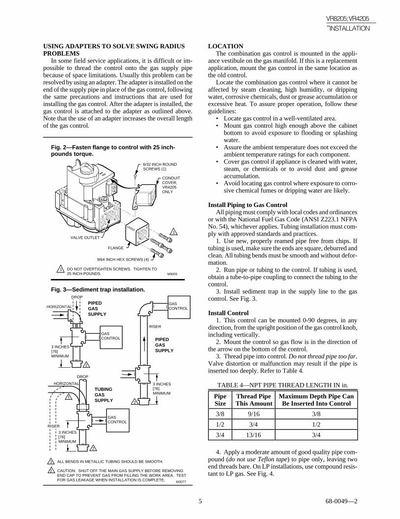
USING ADAPTERS TO SOLVE SWING RADIUSPROBLEMS
In some field service applications, it is difficult or im-possible to thread the control onto the gas supply pipebecause of space limitations. Usually this problem can beresolved by using an adapter. The adapter is installed on theend of the supply pipe in place of the gas control, followingthe same precautions and instructions that are used forinstalling the gas control. After the adapter is installed, thegas control is attached to the adapter as outlined above.Note that the use of an adapter increases the overall lengthof the gas control.
Fig. 2—Fasten flange to control with 25 inch-pounds torque.
M9055
VALVE OUTLET
FLANGE
9/64 INCH HEX SCREWS (4)
6/32 INCH ROUNDSCREWS (1)
CONDUITCOVER,VR4205ONLY
DO NOT OVERTIGHTEN SCREWS. TIGHTEN TO 25 INCH-POUNDS.
1
1
Fig. 3—Sediment trap installation.
GASCONTROL
GASCONTROLHORIZONTAL
DROP
PIPEDGASSUPPLY
PIPEDGASSUPPLY
3 INCHES[76]MINIMUM
3 INCHES[76]MINIMUM
RISER
GASCONTROL
TUBINGGASSUPPLY
HORIZONTAL
DROP
3 INCHES[76]MINIMUM
RISER
M3077
21
2
2
1
2
ALL BENDS IN METALLIC TUBING SHOULD BE SMOOTH.
CAUTION: SHUT OFF THE MAIN GAS SUPPLY BEFORE REMOVINGEND CAP TO PREVENT GAS FROM FILLING THE WORK AREA. TEST FOR GAS LEAKAGE WHEN INSTALLATION IS COMPLETE.
LOCATIONThe combination gas control is mounted in the appli-
ance vestibule on the gas manifold. If this is a replacementapplication, mount the gas control in the same location asthe old control.
Locate the combination gas control where it cannot beaffected by steam cleaning, high humidity, or drippingwater, corrosive chemicals, dust or grease accumulation orexcessive heat. To assure proper operation, follow theseguidelines:
• Locate gas control in a well-ventilated area.• Mount gas control high enough above the cabinet
bottom to avoid exposure to flooding or splashingwater.
• Assure the ambient temperature does not exceed theambient temperature ratings for each component.
• Cover gas control if appliance is cleaned with water,steam, or chemicals or to avoid dust and greaseaccumulation.
• Avoid locating gas control where exposure to corro-sive chemical fumes or dripping water are likely.
Install Piping to Gas ControlAll piping must comply with local codes and ordinances
or with the National Fuel Gas Code (ANSI Z223.1 NFPANo. 54), whichever applies. Tubing installation must com-ply with approved standards and practices.
1. Use new, properly reamed pipe free from chips. Iftubing is used, make sure the ends are square, deburred andclean. All tubing bends must be smooth and without defor-mation.
2. Run pipe or tubing to the control. If tubing is used,obtain a tube-to-pipe coupling to connect the tubing to thecontrol.
3. Install sediment trap in the supply line to the gascontrol. See Fig. 3.
Install Control1. This control can be mounted 0-90 degrees, in any
direction, from the upright position of the gas control knob,including vertically.
2. Mount the control so gas flow is in the direction ofthe arrow on the bottom of the control.
3. Thread pipe into control. Do not thread pipe too far.Valve distortion or malfunction may result if the pipe isinserted too deeply. Refer to Table 4.
TABLE 4—NPT PIPE THREAD LENGTH IN in.
PipeSize
Thread PipeThis Amount
Maximum Depth Pipe CanBe Inserted Into Control
3/8 9/16 3/8
1/2 3/4 1/2
3/4 13/16 3/4
4. Apply a moderate amount of good quality pipe com-pound (do not use Teflon tape) to pipe only, leaving twoend threads bare. On LP installations, use compound resis-tant to LP gas. See Fig. 4.

68-0049—2 6
VR8205; VR4205
INSTALLATION␣ ␣ ␣
Fig. 4—Use moderate amount of pipe com-pound.
Fig. 5—Top view of gas control.
OUTLETPRESSURE TAP
INLET OUTLET
INLETPRESSURE TAP
PRESSURE REGULATORADJUSTMENT (UNDER CAP SCREW)
GAS CONTROL KNOB M9061
GAS CONTROL KNOB
VR4205 CONDUIT COVER
OUTLETPRESSURE TAP
INLET OUTLET
WIRINGTERMINALS (2)
INLETPRESSURE TAP
PRESSURE REGULATORADJUSTMENT (UNDER CAP SCREW)
VR8205
VR4205
5. Remove seals over control inlet and outlet if neces-sary.
6. Connect pipe to control inlet and outlet. Use wrenchon the square ends of the control. If an adapter is used, placewrench on adapter rather than on control. Refer to Figs. 5and 6.
TWO IMPERFECT THREADS GAS CONTROL
THREAD PIPE THE AMOUNT SHOWN IN TABLE 4 FOR INSERTION INTO GAS CONTROL
APPLY A MODERATE AMOUNT OFPIPE COMPOUND TO PIPE ONLY(LEAVE TWO END THREADS BARE).
M3075A
PIPE
Fig. 6—Proper use of wrench on gas control with and without flanges.
APPLY WRENCH FROM TOP OR BOTTOM OF GAS CONTROL TO EITHER SHADED AREA
WHEN FLANGE IS NOT USED
APPLY WRENCHTO FLANGE ONLY
WHEN FLANGE IS USED
M3079

7 68-0049—2
VR8205; VR4205
␣ ␣ ␣ INSTALLATION
WIRINGFollow the wiring instructions furnished by the appli-
ance manufacturer, if available, or use the general instruc-tions provided below. Where these instructions differ fromthe appliance manufacturer, follow the appliance manufac-turer instructions.
All wiring, including insulated quick connect terminals,must comply with applicable electrical codes and ordi-nances.
Disconnect power supply before making wiring connec-tions to prevent electrical shock or equipment damage.
1. Check the power supply rating on the valve and makesure it matches the available supply. Install transformer,thermostat, and other controls as required.
2. For VR4205, when the gas control is installed exter-nal to the appliance, install the conduit cover on the conduitfitting. Do not secure conduit cover at this time.
3. Connect control circuit to gas control terminals. SeeFigs. 5 and 7-9.
NOTE: Use leadwires with insulated terminals.
4. For VR4205, make sure conduit cover is in positionand secured to the gas valve with the screw provided. SeeFig. 2.
5. Adjust thermostat heat anticipator as instructed inappliance manual (i.e., usually 0.1A for VR4205 and 0.5Afor VR8205).
Fig. 7—Wiring connections for 120 volt controlin direct ignition system.
Fig. 8—Wiring connections for 24 volt controlin S87 Direct Ignition System.
IGNITION MODULE
L1(HOT)
L2LIMIT CONTROLLER
Q347 IGNITER-SENSOR
120V (GND)
VALVE
VALVE
GND
POWER SUPPLY. PROVIDE DISCONNECT MEANS AND OVERLOAD PROTECTION AS REQUIRED.
ALTERNATE LIMIT CONTROLLER LOCATION. M3090A
BURNER
120V
VR4205DUAL VALVE COMBINATIONGAS CONTROL
L2
L1
2 1
1
2
WHITE
BLUE
BLACK
BLUE
HOT SURFACEIGNITER-SENSOR
VALVEVALVE (GND)
24VTH-W24V (GND)
GND (BURNER)
S89C,G,J/S890C,G,J HOT SURFACE IGNITION CONTROL
L2HSIL1
HSI
LIMITCONTROLLER
BURNER GROUND
THERMOSTATOR CONTROLLER
DUAL VALVE COMBINATIONGAS CONTROL
POWER SUPPLY. PROVIDE DISCONNECT MEANS AND OVERLOAD PROTECTION AS REQUIRED. MAKE SURE L1 AND L2 ARE NOT REVERSED; THIS WOULD PREVENT FLAME DETECTION.
ALTERNATE LIMIT CONTROLLER LOCATION.
SEN TERMINAL AND Q354 FLAME SENSOR ON D MODELS ONLY.
M9047
MV
MV
L1(HOT)
L2
VENT DAMPER PLUG
1
2
12
3
3
SEN
Q354 FLAMESENSOR
Fig. 9—Wiring connections for 24 volt controlin S89C Direct Ignition System.
24V
24V (GND)
S87 CONTROL MODULE
ALARMVALVEVALVE
GND
TEMPERATURE CONTROLLER
POWER SUPPLY. PROVIDE DISCONNECT MEANS AND OVERLOAD PROTECTION AS REQUIRED.
ALTERNATE LIMIT CONTROLLER LOCATION.
MAXIMUM IGNITER-SENSOR CABLE LENGTH: 3 ft. [.9 m] OR LESS.
3 A REPLACEABLE FUSE.
ALARM TERMINAL PROVIDED ON SOME MODELS. M9043
MV
MV
L1(HOT)
L2
1
2
1
2
3
DUAL VALVECOMBINATIONGAS CONTROL
Q347 IGNITER-SENSOR
BURNER
4
4
5
IGNITER-SENSOR AND BURNER GROUND
3
5
ALARM, IF USED

68-0049—2 8
VR8205; VR4205
STARTUP AND CHECKOUT
Startup and Checkout
! WARNINGFIRE OR EXPLOSION HAZARDCAN CAUSE PROPERTY DAMAGE,SEVERE INJURY OR DEATH1. Do not force the gas control knob on the appli-
ance. Use only your hand to turn the gas con-trol knob. Never use any tools.
2. If the knob will not operate by hand, the con-trol should be replaced by a qualified servicetechnician.
GAS CONTROL KNOB SETTINGSGas control knob settings are as follows:OFF: Prevents main gas flow through the control.ON: Permits gas to flow into the control body. Under
control of the thermostat and direct ignition module,gas can flow to the main burner.
NOTE: Controls are shipped with the gas control knob inthe ON position.
PERFORM GAS LEAK TEST
WARNINGFIRE OR EXPLOSION HAZARDCAN CAUSE PROPERTY DAMAGE,SEVERE INJURY OR DEATHCheck for gas leaks with soap and water solutionany time work is done on a gas system.
GAS LEAK TEST1. Paint pipe connections upstream of gas control with
rich soap and water solution. Bubbles indicate gas leak.2. If leak is detected, tighten pipe connections.3. Stand clear of main burner while lighting to prevent
injury caused from hidden leaks that could cause flashbackin the appliance vestibule. Light main burner.
4. With main burner in operation, paint pipe joints(including adapters) and control inlet and outlet with richsoap and water solution.
5. If another leak is detected, tighten adapter screws,joints, and pipe connections.
6. Replace part if leak cannot be stopped.
TURN ON SYSTEMRotate the gas control knob counterclockwise to
ON.
TURN ON MAIN BURNERFollow instructions provided by appliance manufac-
turer or turn up thermostat to call for heat.
!
CHECK AND ADJUST GAS INPUT ANDBURNER IGNITION
CAUTION1. Do not exceed input rating stamped on appli-
ance nameplate, or manufacturer recommendedburner orifice pressure for size orifice(s) used.Make certain primary air supply to main burneris properly adjusted for complete combustion.Follow appliance manufacturer instructions.
2. IF CHECKING GAS INPUT BY CLOCK-ING GAS METER. Make certain there is nogas flow through the meter other than to theappliance being checked. Other appliances mustremain off with their pilots extinguished (ortheir consumption must be deducted from themeter reading). Convert flow rate to Btuh asdescribed in form 70-2602, Gas Controls Hand-book, and compare to Btuh input rating onappliance nameplate.
3. IF CHECKING GAS INPUT WITH MANO-METER: Be sure gas control is in OFF posi-tion before removing outlet pressure tap plugto connect manometer (pressure gauge). Alsoturn gas control knob back to OFF when re-moving gauge and replacing plug. Before re-moving inlet pressure tap plug, shut off gassupply at the manual valve in the gas piping tothe appliance or, for LP, at the tank. Also shutoff gas supply before disconnecting manom-eter and replacing plug. Repeat Gas Leak Testat plug with main burner operating.
Standard Pressure Regulator1. Check the manifold pressure listed on the appliance
nameplate. Gas control outlet pressure should match thenameplate.
2. With main burner operating, check gas control flowrate using the meter clocking method or check pressure byusing a manometer connected to the outlet pressure tap onthe gas control. See Fig. 5.
3. If necessary, adjust pressure regulator to match ap-pliance rating. See Table 5A or 5B for factory set nominaloutlet pressure and adjustment setting range.
a. Remove pressure regulator adjustment cap screw.b. Using screwdriver, turn inner adjustment screw
clockwise to increase or counterclock-wise to decrease gas pressure to burner.
c. Always replace cap screw and tighten firmly toprevent gas leakage.
4. If desired outlet pressure or flow rate cannot beachieved by adjusting the gas control, check gas controlinlet pressure using a manometer at the gas control inletpressure tap. If inlet pressure is in the nominal range (seeTable 5A or 5B), replace gas control. Otherwise, take thenecessary steps to provide proper gas pressure on thecontrol.
!

9 68-0049—2
VR8205; VR4205
STARTUP AND CHECKOUT
Slow-opening and Step-opening Pressure Regulators1. Check the full rate manifold pressure listed on the
appliance nameplate. Gas control full rate outlet pressureshould match this rating.
2. With main burner operating, check gas control flowrate using the meter clocking method or pressure using amanometer connected to the outlet pressure tap on the gascontrol. See Fig. 5.
3. If necessary, adjust pressure regulator to match ap-pliance rating. See Table 5A or 5B for factory set nominaloutlet pressure and adjustment setting range.
a. Remove pressure regulator adjustment screw.b. Using screwdriver, turn inner adjustment screw
clockwise to increase or counterclock-wise to decrease gas pressure to burner.
c. Always replace cap screw and tighten firmly toprevent gas leakage.
4. If desired outlet pressure or flow rate cannot beachieved by adjusting the gas control, check gas controlinlet pressure using a manometer at the gas control inletpressure tap. If inlet pressure is in the nominal range (seeTable 5A or 5B), replace gas control. Otherwise, take thenecessary steps to provide proper gas pressure to the con-trol.
5. STEP-OPENING PRESSURE REGULATORSONLY. Carefully check burner lightoff at step pressure.Make sure burner lights smoothly and without flashback toorifice. Make sure all ports remain lit. Cycle burner severaltimes, allowing at least 30 seconds between cycles forregulator to resume step function. Repeat after allowingburner to cool. Readjust full rate outlet pressure, if neces-sary, to improve lightoff characteristics.
TABLE 5A—PRESSURE REGULATOR SPECIFICATION PRESSURES (in. wc)
Model Type Nominal InletFactory Set
Nominal Outlet Pressure Setting RangeType of Gas Pressure Range Step Full Rate Step Full Rate
Standard, Natural 5.0 - 7.0 — 3.5 — 3.0 - 5.0
slow-opening LP 12.0 - 14.0 — 10.0 — 8.0 - 12.0
Step-opening Natural 5.0 - 7.0 0.9 3.5 — 3.0 - 5.0
LP 12.0 - 14.0 2.2 10.0 — 8.0 -12.0
TABLE 5B—PRESSURE REGULATOR SPECIFICATION PRESSURES (kPa).
Model Type Nominal InletFactory Set
Nominal Outlet Pressure Setting RangeType of Gas Pressure Range Step Full Rate Step Full Rate
Standard, Natural 1.2 - 1.7 — 0.9 — 0.7 - 1.2
slow-opening LP 2.9 - 3.9 — 2.5 — 2.0 - 3.0
Step-opening Natural 1.2 - 1.7 0.2 0.9 None 0.7 - 1.2
LP 2.9 - 3.9 0.9 2.5 None 2.0 - 3.0
CHECK SAFETY LOCKOUT(SLOW-OPENING CONTROLS ONLY)
1. With the system power off and the thermostat set tocall for heat, manually shut off the gas supply.
2. Energize ignitor control and start timing safety lock-out time. When spark ignition terminates, stop timing.
When using the VR8205H or VR4205H step-openingcontrol, the specified ignitor control safety lockout timemust exceed 8.5 seconds for system to function properly.
3. After spark cutoff, manually reopen gas control knob.No gas should flow to the main burner.
4. Reset system by adjusting thermostat below roomtemperature, waiting 30 seconds, and moving thermostatsetting up to call for heat. Normal ignition should occur.
CHECK SAFETY SHUTDOWN PERFORMANCE
WARNINGFIRE OR EXPLOSION HAZARDCAN CAUSE PROPERTY DAMAGE,SEVERE INJURY OR DEATHPerform the safely shutdown test any time work isdone on a gas system.
NOTE: Read steps 1-7 below before starting and compareto the safety shutdown or safety lockout tests recom-mended for the direct ignition (DI) module. Where theydiffer, use the procedure recommended for the module.
!

68-0049—2 10
VR8205; VR4205
STARTUP AND CHECKOUT • MAINTENANCE • OPERATION
1. Turn off gas supply.2. Set thermostat or controller above room temperature
to call for heat.3. Watch for ignition spark or for glow at hot surface
igniter either immediately or following prepurge. See DImodule specifications.
4. Time the length of the igniter operation. See DImodule specifications.
OperationThe VR8205;VR4205 gas controls provide ON-OFF
manual control of gas flow. In the OFF position, gas flow tothe main burner is mechanically blocked. In the ON posi-tion, gas flows to the main burner under control of thethermostat, the direct ignition (DI) module, and the twoautomatic main valves.
SYSTEM OPERATION WITH MODULEWhen the thermostat calls for heat, the DI module is
energized. The module activates the first and second auto-matic valves of the gas control, which allow gas to flow tothe main burner. At the same time, the DI module generatesa spark at the igniter-sensor to light the main burner.
The second automatic valve diaphragm, controlled bythe servo pressure regulator, opens and adjusts gas flow aslong as the system is powered. The servo pressure regulatormonitors outlet pressure to provide an even flow of gas tothe main burner. Loss of power (thermostat satisfied) de-energizes the DI module and closes the automatic valves.The system is ready to return to normal service when poweris restored through the thermostat.
If the igniter-sensor stops detecting a flame at the mainburner, the trial for ignition is restarted. On DI modules
with lockout timers, the automatic valves are de-energizedand ignition stops after the lockout period. On moduleswithout lockout timers, the trial for ignition continuesindefinitely.
If main burner flame is restarted successfully, operationcontinues as described above. Gas control operation isdescribed in more detail below.
VALVE POSITION DURING THERMOSTAT OFFCYCLE
The valve is positioned as shown in Fig. 10 when the:• manual gas control knob is in the ON position.• thermostat is not calling for heat.The first automatic valve is closed. The second auto-
matic valve operator is de-energized, closing the channel tothe pressure regulator, and opening a channel to the under-side of the second automatic valve operator valve dia-phragm. The combination of spring pressure under thesecond automatic valve diaphragm and lack of outlet pres-sure holds the diaphragm firmly closed. Gas flow to themain burner is blocked by both valves.
Regular preventive maintenance is important in applica-tions that place a heavy load on systems controls, such as inthe commercial cooking and agricultural and industrialindustries because:
• In many such applications, particularly commercialcooking, the equipment operates 100,000-200,000cycles per year. Such heavy cycling can wear out thegas control in one to two years.
• Exposure to water, dirt, chemicals and heat can dam-age the gas control and shut down the control system.
The maintenance program should include regular check-out of the gas control, see Startup and Checkout section,and the control system as described in the appliance manu-facturer literature.
Maintenance frequency must be determined individu-ally for each application. Some considerations are:
• Cycling frequency. Appliances that may cycle 20,000times annually should be checked monthly.
• Intermittent use. Appliances that are used seasonallyshould be checked before shutdown and again beforethe next use.
• Consequence of unexpected shutdown. Where thecost of an unexpected shutdown would be high, thesystem should be checked more often.
• Dusty, wet, or corrosive environment. Since theseenvironments can cause the gas control to deterioratemore rapidly, the system should be checked moreoften.
Gas valves exposed to high ammonia conditions; i.e.,those used in greenhouses or animal barns, may fail in oneor two years. Contact your Honeywell sales representativeto request a gas valve with corrosion resistant construction.The gas control should be replaced if:
• It does not perform properly on checkout or trouble-shooting.
• The gas control knob is hard to turn.• The gas controls is likely to have operated for more
than 200,000 cycles.
Maintenance
5. After the module locks out, open manual gas cockand make sure no gas is flowing to the burner.
6. Set the thermostat below room temperature and waitone minute.
7. Operate system through one complete cycle to makesure all controls operate properly.

11 68-0049—2
VR8205; VR4205
␣ ␣ ␣ ␣ ␣ ␣ ␣OPERATION
WHEN THERMOSTAT CALLS FOR HEATWhen the thermostat calls for heat, the DI module
generates a spark at the main burner and the first automaticvalve and second automatic valve operators are energized(Fig. 11). The first automatic valve opens, and the secondautomatic valve operator valve disc is lifted off its seat.This diverts gas flow from the second automatic valvediaphragm, and causes a reduction of pressure on theunderside of this diaphragm. The reduced pressure on thebottom of the automatic valve diaphragm repositions thediaphragm downward, away from the valve seat, allowinggas to flow to the main burner.
Standard RegulationDuring the ON cycle, the servo pressure regulator pro-
vides close control of outlet pressure, even if inlet pressureand flow rate vary widely. Any outlet pressure change is
immediately reflected back to the pressure regulator dia-phragm, which repositions to change the flow rate throughthe regulator valve, and thus through the automatic valve.
If outlet pressure begins to rise, the pressure regulatordiaphragm moves slightly higher, allowing less gas flow tothe gas control outlet. This increases gas pressure under theautomatic valve diaphragm and repositions the valve disccloser to the seat. Thus, flow of gas through the secondautomatic valve is reduced, and outlet pressure falls to thedesired level.
If outlet pressure begins to fall, the pressure regulatordiaphragm moves slightly lower, allowing more gas flow tothe gas control outlet. This decreases gas pressure under thesecond automatic valve diaphragm and repositions thevalve disc further from the seat. Thus, flow of gas throughthe second automatic valve is increased. and outlet pressurerises to the desired level.
Fig. 10—Position of gas control components during thermostat off cycle.
Slow-Opening RegulationSlow-opening gas controls function the same as stan-
dard models except that when the thermostat calls for heat,the second automatic valve opens gradually. Opening isslowed because a flow restructure in the passage from thesecond automatic operator slows the rate at which gaspressure is reduced under the second automatic valve dia-phragm after the second automatic operator opens. Outletpressure to the main burner increases gradually from 0 in.
wc [0 kPa] to rated output pressure within 3-6 seconds (foran 80,000 Btuh furnace at 7 in. wc [1.8 kPa] inlet pressureand 3.5 in. wc [0.9 kPa] outlet pressure).
Step-Opening RegulationStep-opening gas controls actually combine two pres-
sure regulators, one for the low pressure and one for thefull-rate pressure. When the thermostat calls for heat, theautomatic operator valve disc opens. The low pressure
FIRST AUTOMATICVALVE SOLENOID
CONTROLKNOB
GAS CONTROL INLET
SECOND AUTOMATICVALVE OPERATOR
SECOND AUTOMATICOPERATOR SOLENOID
SECOND AUTOMATICOPERATOR VALVE DISC
SERVO PRESSURE REGULATOR
GAS CONTROL OUTLET
SECOND AUTOMATICVALVE DIAPHRAGM
FIRST AUTOMATIC VALVE
NOTE: AUTOMATIC VALVE OPERATOR AND SERVO PRESSURE REGULATOR SHOWN OUTSIDE GAS CONTROL FOR EASE IN TRACING GAS FLOW. SLOW-OPENING GAS CONTROL HAS A GAS FLOW RESTRICTOR IN THIS PASSAGE. M9114
1
1

68-0049—2 12
VR8205; VR4205
OPERATION • SERVICE
regulator maintains outlet pressure at the preset step rate forseveral seconds. Then the regulator valve is forced fullyopen by the timing diaphragm, which is operated by bleedgas. When the low pressure regulator is fully open, the highpressure regulator maintains the desired full-rate outletpressure as described for the standard regulator.
The step model requires approximately 60 seconds toreset once the main burner goes off. If it is reenergizedwithin 60 seconds, it may bypass or shorten the length ofthe low pressure step. The burner may relight at the fullflow rate.
WHEN THE CALL FOR HEAT ENDSWhen the call for heat ends, the first automatic valve and
the second automatic valve operator close, bypassing theregulator(s) and shutting off the main burner and the pilot.As pressure inside the gas control and underneath theautomatic valve diaphragm equalizes, spring pressure closesthe second automatic valve to provide a second barrier togas flow.
Fig. 11—Position of gas control components during burner on cycle.
Service
! !WARNINGFIRE OR EXPLOSION HAZARDCAN CAUSE PROPERTY DAMAGE,SEVERE INJURY OR DEATHDo not disassemble the gas control; it contains noreplaceable components. Attempted disassemblyor repair may damage the control.
CAUTIONDo not apply a jumper across (or short) the valvecoil terminals, even temporarily. Doing so mayburn out the heat anticipator in the thermostat ordamage the DI module.
IMPORTANT: Allow 60 seconds after shutdown beforere-energizing step-opening model to assure lightoffat step pressure.
FIRST AUTOMATICVALVE SOLENOID
CONTROLKNOB
GAS CONTROL INLET
SECOND AUTOMATICVALVE OPERATOR
SECOND AUTOMATICOPERATOR SOLENOID
SECOND AUTOMATICOPERATOR VALVE DISC
SERVO PRESSURE REGULATOR
GAS CONTROL OUTLET
SECOND AUTOMATICVALVE DIAPHRAGM
FIRST AUTOMATIC VALVE
NOTE: SECOND AUTOMATIC VALVE OPERATOR AND SERVO PRESSURE REGULATOR SHOWN OUTSIDE GAS CONTROL FOR EASE IN TRACING GAS FLOW. SLOW-OPENING GAS CONTROL HAS A GAS FLOW RESTRICTOR IN THIS PASSAGE. M9115
1
1

13 68-0049—2
VR8205; VR4205
␣␣ ␣ ␣ ␣ ␣ ␣ ␣ ␣ ␣ ␣ ␣SERVICE
IF MAIN BURNER WILL NOT COME ON WITHCALL FOR HEAT
1. Confirm that gas control knob is in the ON position.2. Adjust thermostat several degrees above room tem-
perature.3. Using ac voltmeter, measure voltage across MV
terminals at gas control.4. If no voltage is present, check control circuit for
proper operation.5. If proper control system voltage is present, replace
gas control.
INSTRUCTIONS TO THE HOMEOWNERFOR YOUR SAFETY, READ BEFORE LIGHTING
WARNINGIF YOU DO NOT FOLLOW THEWARNINGS BELOW AND THELIGHTING INSTRUCTIONS EXACTLY, AFIRE OR EXPLOSION CAN RESULTWITH PROPERTY DAMAGE, PERSONALINJURY OR LOSS OF LIFE.1. Before lighting, smell around the appliance
area for gas. If the appliance uses LP (bottled)gas, be sure to smell next to the floor becauseLP gas is heavier than air. If you smell gas,immediately shut off the manual valve in thegas piping to the appliance, or on LP, at thetank. Do not try to light any appliance. Do nottouch any electrical switch or use the phone.Leave the building and call your gas supplier.If your gas supplier cannot be reached, call thefire department.
2. Do not force the gas control knob on the appli-ance. Use only your hand to turn the gas con-trol knob. Never use any tools. If the knob willnot operate by hand, replace the control using aqualified service technician. Force or attemptedrepair can result in fire or explosion.
3. The gas control must be replaced if it has beenflooded with water. Call a qualified servicetechnician.
4. The gas control is a safety device. It must bereplaced in case of any physical damage suchas bent terminals, missing or broken parts,stripped threads, or evidence of exposure toheat.
IMPORTANT: Follow the operating instructions pro-vided by the manufacturer of your heating appliance.The information below will be of assistance in atypical control application, but the specific controlsused and the procedures outlined by the manufac-turer of your appliance may differ, requiring specialinstructions.
TO TURN ON FURNACESTOP: Read the safety information above.
1. The lighting sequence on this appliance is automatic;do not attempt to manually light the main burner.
2. If the furnace does not come on when the thermostatis set several degrees above room temperature, set thethermostat to the bottom of its range to reset safety control.
3. Remove burner access panel if provided on yourappliance.
4. Turn the gas control knob (Fig. 5) clockwise toOFF.
5. Wait five minutes to allow any gas in the combustionchamber to vent. If you then smell gas in the appliance areaor near the floor in an LP installation, immediately shut offthe manual valve in the gas piping to the appliance, or onLP, at the tank. Do not touch any electrical switch or use thephone. Leave the building and call your gas supplier. Ifyour gas supplier cannot be reached, call the fire depart-ment. Failure to do so may result in fire or explosion.
6. If you don’t smell gas, turn knob on gas controlcounterclockwise to ON.
7. Replace burner access panel.8. Reset thermostat to desired temperature.9. If burner does not come on when room temperature is
below thermostat setting, turn gas control knob to OFF andcontact a qualified service technician for assistance.
TO TURN OFF APPLIANCETurn gas control knob clockwise to OFF.
!

68-0049—2 14

15 68-0049—2

68-0049—2 16
Home and Building Control Home and Building Control Helping You Control Your WorldHoneywell Inc. Honeywell Limited—Honeywell Limitée1985 Douglas Drive North 740 Ellesmere RoadGolden Valley, MN 55422 Scarborough, Ontario
M1P 2V9
Printed in U.S.A.
QUALITY IS KEY