663 426 552 - Juillet 2010 Aircraft Specification Specification Falcon 900LX Dassault Falcon Jet...
19
Aircraft Specification Falcon 900LX DGAC-DMF8002C July 2010
Transcript of 663 426 552 - Juillet 2010 Aircraft Specification Specification Falcon 900LX Dassault Falcon Jet...

AircraftSpecificationFalcon 900LX
Dassault Falcon JetTeterboro Airport, Box 2000, South Hackensack, NJ 07606Phone: (1) 201-440-6700Fax: (1) 201-541-4469
Dassault AviationCedex 300 - 92552 Saint Cloud Cedex - FrancePhone: 33 (0) 1 47 11 82 82Fax: 33 (0) 1 47 11 89 17
DGAC-DMF8002C
July 2010
DG
AC
-DM
F800
2Ca
rmo
n@ -
+33
(0)
663
426
552
- J
uille
t 201
0

DGAC-DMF8002C July2010
FALCON900LX
F A L C O NF A L C O NDASSAULTDASSAULT
Aircraft Specification© Copyright Dassault Aviation, July 2010
2
© C
opyright Dassault A
viation, July 2010
Note:
Dassault Aviation reserves the right to substitute equipment in lieu of that specified herein, whenever such substitution is deemed necessary to pre-vent delay in delivery, improve the product, or meet the requirements of the appropriate airworthiness authorities.
3
© C
opyr
ight
Das
saul
t A
viat
ion,
Jul
y 20
10
TOpiC pAGe
Aircraft DescriptionGeneral ................................................................................................................................................... 5Certification ............................................................................................................................................ 5Layout .................................................................................................................................................... 5Structure................................................................................................................................................. 5Three view drawing ................................................................................................................................ 6Dimensions ............................................................................................................................................ 7 • Airframe .................................................................................................................................... 7 • Cabin ........................................................................................................................................ 7 • Landing Gear ............................................................................................................................ 7Limitations .............................................................................................................................................. 8 • Weights ..................................................................................................................................... 8 • CG Location ............................................................................................................................. 8 • Fuel Quantity ............................................................................................................................ 8 • Speeds...................................................................................................................................... 8 • Altitude and Temperatures ....................................................................................................... 8Guaranteed Performance ...................................................................................................................... 9 • Approach Speed ...................................................................................................................... 9 • Takeoff Distance ....................................................................................................................... 9 • Landing Distance ..................................................................................................................... 9 • Range ....................................................................................................................................... 9 • Assumptions ............................................................................................................................. 9
Passenger CabinInterior layout ......................................................................................................................................... 10General Description ............................................................................................................................... 11Entryway - Galley ................................................................................................................................... 11Forward Lounge ..................................................................................................................................... 11Mid Cabin ............................................................................................................................................... 11Rear Lounge .......................................................................................................................................... 11Lavatory ................................................................................................................................................. 11Baggage Compartment ......................................................................................................................... 11Interior Finishing..................................................................................................................................... 11
SystemsEngines................................................................................................................................................... 12Thrust Reverser ...................................................................................................................................... 12Fuel System ........................................................................................................................................... 12Hydraulic System ................................................................................................................................... 12Flight Controls ........................................................................................................................................ 12Landing Gear ......................................................................................................................................... 13Electrical System ................................................................................................................................... 13Pneumatic System ................................................................................................................................. 13Auxiliary Power Unit ............................................................................................................................... 14Ice and Rain Protection ......................................................................................................................... 14Fire Protection System .......................................................................................................................... 14Oxygen System...................................................................................................................................... 14Avionics .................................................................................................................................................. 15

4
© C
opyright Dassault A
viation, July 2010
Page intentionally left blank
5
© C
opyr
ight
Das
saul
t A
viat
ion,
Jul
y 20
10
GeNeRAL
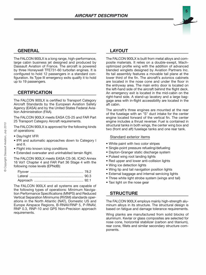
The FALCON 900LX is a long range, high-performance, large cabin business jet designed and produced by Dassault Aviation of France. The aircraft is powered by three Honeywell TFE731-60 turbofan engines. It is configured to hold 12 passengers in a standard con-figuration. Its Type III emergency exits qualify it to hold up to 19 passengers.
CeRTiFiCATiON
The FALCON 900LX is certified to Transport Category Aircraft Standards by the European Aviation Safety Agency (EASA) and by the United States Federal Avia-tion Administration (FAA).
The FALCON 900LX meets EASA CS-25 and FAR Part 25 Transport Category Aircraft requirements.
The FALCON 900LX is approved for the following kinds of operations:
• Day/night VFR• IFR and automatic approaches down to Category I
and II.• Flight into known icing conditions• Extended overwater and uninhabited terrain flight.
The FALCON 900LX meets EASA CS-36, ICAO Annex 16 Vol1 Chapter 4 and FAR Part 36 Stage 4 with the following noise levels (EPNdB):
Flyover ......................................................... 78.2Lateral .......................................................... 90.3Approach ..................................................... 92.1
The FALCON 900LX and all systems are capable of the following types of operations: Minimum Naviga-tion Performance Specifications (MNPS) and Reduced Vertical Separation Minimums (RVSM) standards oper-ations in the North Atlantic (NAT), Domestic US and Europe Airspace Regions, B-RNAV/RNP 5, P-RNAV, RNP 0.3, RNP-10 and GPS Non-Precision approach requirements.
LAYOUT
The FALCON 900LX is built from metal alloys and com-posite materials. It relies on a double-swept, Mach-optimized profile wing with the addition of advanced blended winglets designed by Aviation Partners Inc. Its tail assembly features a movable tail plane at the lower third of the fin. The aircraft’s avionics cabinets are located in the nose cone and under the floor in the entryway area. The main entry door is located on the left-hand side of the aircraft behind the flight deck. An emergency exit is located in the mid-cabin on the right-hand side. A stand-up lavatory and a large bag-gage area with in-flight accessibility are located in the aft cabin.
The aircraft’s three engines are mounted at the rear of the fuselage with an "S" duct intake for the center engine located forward of the vertical fin. The center engine includes a thrust reverser. Fuel is contained in structural tanks in both wings, the center wing box and two (front and aft) fuselage tanks and one rear tank.
Standard exterior items
• White paint with two color stripes• Single-point pressure refueling/defueling• Dayton-Granger static discharge system• Pulsed wing root landing lights• Red upper and lower anti-collision lights• Wing ice detection lights• Wing tip and tail navigation position lights• External baggage and internal servicing lights• Three white light strobe system (wings and tail)• Taxi light on the nose gear
STRUCTURe
The FALCON 900LX employs mainly high-strength alu-minum alloys in its structure. The structural design is based on fatigue and damage tolerance requirements.
Wing planks are manufactured from solid blocks of aluminum. Kevlar or glass composites are selected for nose cone, horizontal stabilizer (carbon and titanium), rear cone, fillets and similar secondary structure com-ponents.
AircrAft deScription

6
© C
opyright Dassault A
viation, July 2010
AircrAft deScription
Threeviewdrawing70
ft 2
in
2.50
m
24 ft 9 in7.55 m
25 ft 11 in - 7.90 m
21.3
8 m
98.4
in
14 ft 7.2 in4.45 m
66 ft 4 in - 20.21 m
7
© C
opyr
ight
Das
saul
t A
viat
ion,
Jul
y 20
10
AircrAft deScription
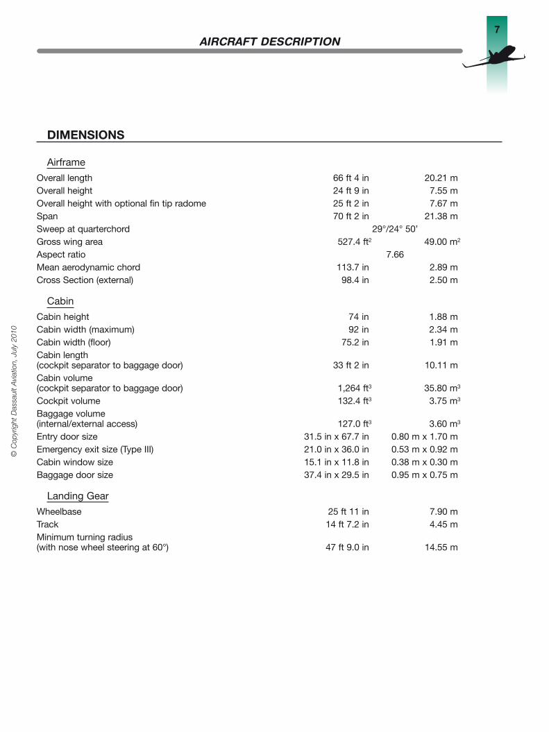
DiMeNSiONS
Airframe
Overall length 66 ft 4 in 20.21 mOverall height 24 ft 9 in 7.55 mOverall height with optional fin tip radome 25 ft 2 in 7.67 mSpan 70 ft 2 in 21.38 mSweep at quarterchord 29°/24° 50’Gross wing area 527.4 ft2 49.00 m2
Aspect ratio 7.66Mean aerodynamic chord 113.7 in 2.89 mCross Section (external) 98.4 in 2.50 m
Cabin
Cabin height 74 in 1.88 mCabin width (maximum) 92 in 2.34 mCabin width (floor) 75.2 in 1.91 mCabin length (cockpit separator to baggage door) 33 ft 2 in 10.11 mCabin volume (cockpit separator to baggage door) 1,264 ft3 35.80 m3
Cockpit volume 132.4 ft3 3.75 m3
Baggage volume (internal/external access) 127.0 ft3 3.60 m3
Entry door size 31.5 in x 67.7 in 0.80 m x 1.70 mEmergency exit size (Type III) 21.0 in x 36.0 in 0.53 m x 0.92 mCabin window size 15.1 in x 11.8 in 0.38 m x 0.30 mBaggage door size 37.4 in x 29.5 in 0.95 m x 0.75 m
Landing Gear
Wheelbase 25 ft 11 in 7.90 mTrack 14 ft 7.2 in 4.45 mMinimum turning radius (with nose wheel steering at 60°) 47 ft 9.0 in 14.55 m
8
© C
opyright Dassault A
viation, July 2010
AircrAft deScription
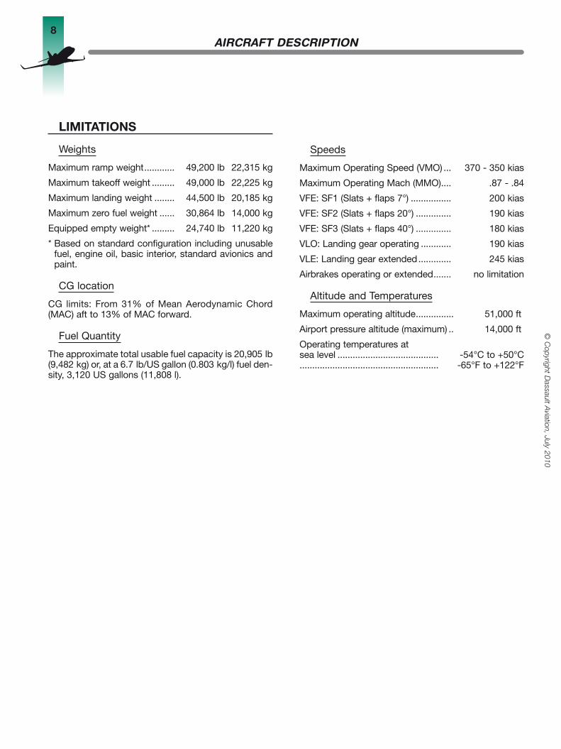
LiMiTATiONS
Weights
Maximum ramp weight ............ 49,200 lb 22,315 kg
Maximum takeoff weight ......... 49,000 lb 22,225 kg
Maximum landing weight ........ 44,500 lb 20,185 kg
Maximum zero fuel weight ...... 30,864 lb 14,000 kg
Equipped empty weight* ......... 24,740 lb 11,220 kg
* Based on standard configuration including unusable fuel, engine oil, basic interior, standard avionics and paint.
CG location
CG limits: From 31% of Mean Aerodynamic Chord (MAC) aft to 13% of MAC forward.
Fuel Quantity
The approximate total usable fuel capacity is 20,905 lb (9,482 kg) or, at a 6.7 lb/US gallon (0.803 kg/l) fuel den-sity, 3,120 US gallons (11,808 l).
Speeds
Maximum Operating Speed (VMO) ... 370 - 350 kias
Maximum Operating Mach (MMO) .... .87 - .84
VFE: SF1 (Slats + flaps 7°) ................ 200 kias
VFE: SF2 (Slats + flaps 20°) .............. 190 kias
VFE: SF3 (Slats + flaps 40°) .............. 180 kias
VLO: Landing gear operating ............ 190 kias
VLE: Landing gear extended ............. 245 kias
Airbrakes operating or extended ....... no limitation
Altitude and Temperatures
Maximum operating altitude ............... 51,000 ft
Airport pressure altitude (maximum) .. 14,000 ft
Operating temperatures at sea level ........................................ -54°C to +50°C....................................................... -65°F to +122°F

9
© C
opyr
ight
Das
saul
t A
viat
ion,
Jul
y 20
10
GUARANTeeDpeRFORMANCe
Takeoff Distance
Balanced Field Length(Maximum Takeoff Weight, Sea Level, ISA)
49,000 lb (22,225 kg) ...................... 5,360 ft (1,633 m)**
Range
Basic Operating Weight(6 passengers, 2 crew, Sea Level, full fuel, NBAA IFR reserves LRC*, ISA, no wind)
25,815 lb (11,710 kg) ................ 4,750 nm (8,800 km)**
Approach Speed (Vref)
(FAR 91, 6 passengers, 2 crew, Sea Level, NBAA IFR reserves)
28,960 lb (13,136 kg) ................. 110 kias*
Landing Distance
44,500 lb (20,185 kg) ...................... 3,670 ft (1,118 m)**(Maximum landing weight) (sea level, ISA)
28,960 lb (13,136 kg) ....................... 2,415 ft (736 m)**(FAR 91, 6 passengers, Sea Level, NBAA IFR reserves)
* Guaranteed Performance (±3%)** Guaranteed Performance (±5%)
AircrAft deScription
Assumptions
The performance data are based on these conditions:
• Equipped empty weight: 24,740 lb (11,220 kg) with standard configuration including paint.
• In accordance with EASA CS-25 and FAR Part 25 Transport Category Aircraft requirements, takeoff and landing performance data are calculated on the basis of a smooth, hard, dry-surfaced runway with zero wind, no slope, and an anti-skid system in operation.
• Range is determined by using the NBAA IFR fuel reserves performed in still air at standard atmo-sphere. Includes climb, cruise at three flight levels (maximum), and descent.
• The fuel quantity allows (in addition to the planned distance flown): 10 minutes of taxiing, 1 minute of takeoff, and NBAA IFR reserves [(one approach, one go-around, holding for five minutes at 5,000 ft (1,524 m), a flight of 200 nm (370 km) to an alternate airport, and holding for up to 30 minutes at 5,000 ft) (1,524 m)].
• The fuel is assumed to have a heating value of 18,400 BTU/lb (42,800 kN/kg) and a density of 6.7 lb/US gallon (0.803 kg/l).

10
© C
opyright Dassault A
viation, July 2010
pASSenger cAbin
interiorlayout
Flight DeckFire Extinguisher
Portable Oxygen Bottle
25 in Closet with Curtain close-out
36 in Galley-Bar Cabinet
Service Ledge StorageCompartment
Table StorageCompartment
Mid-Cabin Multi-PurposeStorage Cabinets
Executive Console Table (28 in x 18 in)
Magazine Rack
ExecutiveSingle Seat
R/H Flight Deck Closet
Electric Flushing Toilet with External Servicing
Fire Extinguisher
Magazine Rack
Folding StowableConsole Table(28 in x 24 in)
L/H Flight DeckCloset
Entryway AcousticalCurtain
Vanity Cabinet withHot & Cold Water
& Storage
3-Place Divan (76 in)with Berthing Extension
& Life Raft Storage
Fire Extinguisher
30 in Auxiliary Galley/Entertainment Cabinet
Single Seats(20 in wide)
Dining Seats(20 in wide)
High/Low Dining/Conference Table
(46 in x 28 in)
Armrest StorageCabinet
Armrest StorageCabinet
Oxygen Bottle

11
© C
opyr
ight
Das
saul
t A
viat
ion,
Jul
y 20
10
pASSenger cAbin
GeNeRALDeSCRipTiON
The passenger cabin is soundproofed and insulated, and measures 33 ft 2 in (10.11 m) in length including an aft lavatory. It is configured with 12 passenger seats. Each individual passenger seat is provided with an ashtray and cupholder module, a cold air outlet and a reading light. A stowable, folding console table is installed for each pair of facing seats and the aft right-hand single seat.
Two indirect lighting systems provide general lighting throughout the cabin. Table lights are also provided.
Emergency equipment, including a first-aid kit, smoke hood, life jackets vests and life rafts, are provided on the aircraft. Oxygen masks are installed for all passen-gers and in the lavatory.
A maintenance ladder is installed in the baggage com-partment.
Entryway - Galley
The aircraft main entry door is located on the forward, left-hand side of the fuselage. Two crew closets, one left-hand and one right-hand, are installed forward of the door.
A 36-in galley-bar cabinet and a 25-in main cabin closet are located on the right-hand side of the cabin and opposite the entry door. It offers adequate work surfaces and includes:• an automatic cappuccino/espresso coffee machine with
hot/cold water spigot and dedicated remote water tank,• an extra wide high temperature oven• two chests (ice and cold)• storage drawers• a trash container• a sink supplied with hot and cold water supply• glass storage racks.
On the left-hand side, beside the door, is a 30 in auxil-iary galley/entertainment cabinet which includes:• Entertainment equipment• Microwave oven• Storage drawers• 4 Atlas tray carriers
Forward Cabin
The forward lounge features four (20 in wide) individual seats arranged in facing pairs on the left and right-hand sides of the cabin.
Each seat includes floor tracking, base tracking, side tracking, swivel, full flat recline (berthing), integral headrests and retractable armrests, electrically con-trolled lumbar.
Each pair of seats is provided with a folding, stowable 28 in x 24 in console table.
Mid cabin
On the left-hand side is a lounge including two pairs of 20-in seats separated by a 46 in x 28 in folding and electrically hi-lo operating coffee/dining table. On the right-hand side are multipurpose storage cabinets.
Aft Cabin
On the left-hand side is a three place divan convertible for berthing. On the other side is a 20-in seat, identical to those in the forward lounge, with a folding stowable 28 in x 18 in console table.
Lavatory
The lavatory is equipped with an electric flushing toilet on the right-hand and a vanity cabinet on the left-hand side of the compartment. The vanity cabinet includes a sink with hot and cold running water.
The external toilet-servicing connector is located on the right-hand side of the compartment. The galley and the lavatory are supplied through a centralized water system, which can be drained externally. It also has an internal filler cap and gauge.
To ensure privacy, the lavatory compartment is sepa-rated from the cabin by a door.
Baggage Compartment
The compartment’s volume is 127 ft3 (3.6 m3). Access to the baggage compartment is available from inside or outside the aircraft. The compartment is lined and features garment hanger racks in the forward area and folding shelves to maximize baggage storage.
Interior Finishing
The cabin provides generous proportions for comfort and ease of movement during lengthy flights. Each interior is finished with:
Headliner, Flight deck: ...................Ultra Leather/suedeHeadliner, Main Cabin: ..................Ultra Leather/suedeWindow Panels, Shades: ....Fabric/Ultra Leather/suedeService Ledges, Main Cabin: ............................ LeatherLower Sidewalls, Main Cabin: ................Leather/FabricCarpet: ................................... High-Quality, 100% WoolBulkheads & Doors: ..................................Wood VeneerCabinetry: ............................ Wood Veneer & LaminatesMetal Finish: .................................... Brushed AluminumTables: ............................Composite with Wood VeneerSeats: ................................................Fabrics or LeatherCloset/Baggage Compartment Lining: ......... Grospoint
12
© C
opyright Dassault A
viation, July 2010
SyStemS
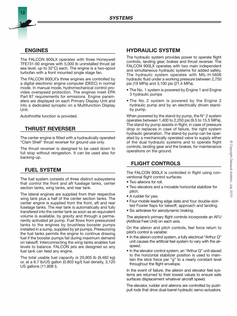
eNGiNeS
The FALCON 900LX operates with three Honeywell TFE731-60 engines with 5,000 lb uninstalled thrust (at sea level, up to 32°C) each. The engine is a two-spool turbofan with a front mounted single stage fan.
The FALCON 900LX’s three engines are controlled by a digital electronic engine computer (DEEC) in normal mode. In manual mode, hydromechanical control pro-vides overspeed protection. The engines meet EPA Part 87 requirements for emissions. Engine param-eters are displayed on each Primary Display Unit and into a dedicated synoptic on a Multifunction Display Unit.
Autothrottle function is provided.
THRUSTReVeRSeR
The center engine is fitted with a hydraulically operated “Clam Shell” thrust reverser for ground use only.
The thrust reverser is designed to be used down to full stop without reingestion. It can be used also for backing-up.
FUeLSYSTeM
The fuel system consists of three distinct subsystems that control the front and aft fuselage tanks, center section tanks, wing tanks, and rear tank.
The lateral engines are supplied from their respective wing tank plus a half of the center section tanks. The center engine is supplied from the front, aft and rear fuselage tanks. The rear tank is automatically and fully transfered into the center tank as soon as an equivalent volume is available, by gravity and through a perma-nently activated jet pump. Fuel flows from pressurized tanks to the engines by brushless booster pumps installed in a sump, supplied by jet pumps. Pressurizing the fuel tanks permits the engine to continue drawing fuel if the booster pumps fail during maximum demand on takeoff. Interconnecting the wing tanks enables fuel levels to balance. FALCON jets are designed so any fuel tank can feed any engine.
The total usable fuel capacity is 20,905 lb (9,482 kg) or, at a 6.7 lb/US gallon (0.803 kg/l) fuel density, 3,120 US gallons (11,808 l).
HYDRAULiCSYSTeMThe hydraulic system provides power to operate flight controls, landing gear, brakes and thrust reverser. The FALCON 900LX operates with two main independent and simultaneous hydraulic systems for added safety. The hydraulic system operates with MIL-H-5606 hydraulic fluid under a working pressure between 2,750 psi (19 MPa) and 3,100 psi (21.4 MPa).
• The No. 1 system is powered by Engine 1 and Engine 3 hydraulic pumps
• The No. 2 system is powered by the Engine 2 hydraulic pump and by an electrically driven stand-by pump.
When powered by the stand-by pump, the N° 2 system operates between 1,400 to 2,250 psi (9.5 to 15.5 MPa). The stand-by pump assists in flight, in case of pressure drop or replaces in case of failure, the right system hydraulic generation. The stand-by pump can be oper-ated by a mechanically operated valve to supply either of the dual hydraulic systems and to operate flight controls, landing gear and the brakes, for maintenance operations on the ground.
FLiGHTCONTROLS
The FALCON 900LX is controlled in flight using con-ventional flight control surfaces:• Two ailerons for roll.• Two elevators and a movable horizontal stabilizer for
pitch.• A rudder for yaw.• Four mobile leading edge slats and four double-slot-
ted Fowler flaps for takeoff, approach and landing.• Six airbrakes for aerodynamic braking.
The airplane’s primary flight controls incorporate an AFU (Artificial Feel Unit) on each axis.
On the aileron and pitch controls, feel force return to pilot’s control is variable:• In the aileron control system, a fully electrical “Arthur Q”
unit causes the artificial feel system to vary with the air-speed.
• In the elevator control system, an “Arthur Q” unit slaved to the horizontal stabilizer position is used to main-tain the stick force per “g” to a nearly constant level throughout the flight envelope.
In the event of failure, the aileron and elevator feel sys-tems are returned to their lowest values to ensure safe surfaces displacement whatever aircraft speed.
The elevator, rudder and ailerons are controlled by push-pull rods that drive dual-barrel hydraulic servo-actuators.
13
© C
opyr
ight
Das
saul
t A
viat
ion,
Jul
y 20
10
SyStemS
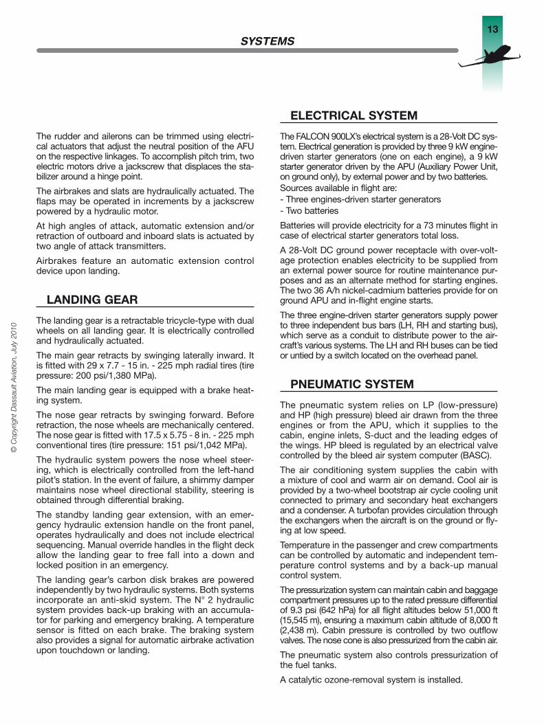
The rudder and ailerons can be trimmed using electri-cal actuators that adjust the neutral position of the AFU on the respective linkages. To accomplish pitch trim, two electric motors drive a jackscrew that displaces the sta-bilizer around a hinge point.
The airbrakes and slats are hydraulically actuated. The flaps may be operated in increments by a jackscrew powered by a hydraulic motor.
At high angles of attack, automatic extension and/or retraction of outboard and inboard slats is actuated by two angle of attack transmitters.
Airbrakes feature an automatic extension control device upon landing.
LANDiNGGeAR
The landing gear is a retractable tricycle-type with dual wheels on all landing gear. It is electrically controlled and hydraulically actuated.
The main gear retracts by swinging laterally inward. It is fitted with 29 x 7.7 - 15 in. - 225 mph radial tires (tire pressure: 200 psi/1,380 MPa).
The main landing gear is equipped with a brake heat-ing system.
The nose gear retracts by swinging forward. Before retraction, the nose wheels are mechanically centered. The nose gear is fitted with 17.5 x 5.75 - 8 in. - 225 mph conventional tires (tire pressure: 151 psi/1,042 MPa).
The hydraulic system powers the nose wheel steer-ing, which is electrically controlled from the left-hand pilot’s station. In the event of failure, a shimmy damper maintains nose wheel directional stability, steering is obtained through differential braking.
The standby landing gear extension, with an emer-gency hydraulic extension handle on the front panel, operates hydraulically and does not include electrical sequencing. Manual override handles in the flight deck allow the landing gear to free fall into a down and locked position in an emergency.
The landing gear’s carbon disk brakes are powered independently by two hydraulic systems. Both systems incorporate an anti-skid system. The N° 2 hydraulic system provides back-up braking with an accumula-tor for parking and emergency braking. A temperature sensor is fitted on each brake. The braking system also provides a signal for automatic airbrake activation upon touchdown or landing.
eLeCTRiCALSYSTeM
The FALCON 900LX’s electrical system is a 28-Volt DC sys-tem. Electrical generation is provided by three 9 kW engine-driven starter generators (one on each engine), a 9 kW starter generator driven by the APU (Auxiliary Power Unit, on ground only), by external power and by two batteries.Sources available in flight are:- Three engines-driven starter generators- Two batteries
Batteries will provide electricity for a 73 minutes flight in case of electrical starter generators total loss.
A 28-Volt DC ground power receptacle with over-volt-age protection enables electricity to be supplied from an external power source for routine maintenance pur-poses and as an alternate method for starting engines. The two 36 A/h nickel-cadmium batteries provide for on ground APU and in-flight engine starts.
The three engine-driven starter generators supply power to three independent bus bars (LH, RH and starting bus), which serve as a conduit to distribute power to the air-craft’s various systems. The LH and RH buses can be tied or untied by a switch located on the overhead panel.
pNeUMATiCSYSTeM
The pneumatic system relies on LP (low-pressure) and HP (high pressure) bleed air drawn from the three engines or from the APU, which it supplies to the cabin, engine inlets, S-duct and the leading edges of the wings. HP bleed is regulated by an electrical valve controlled by the bleed air system computer (BASC).
The air conditioning system supplies the cabin with a mixture of cool and warm air on demand. Cool air is provided by a two-wheel bootstrap air cycle cooling unit connected to primary and secondary heat exchangers and a condenser. A turbofan provides circulation through the exchangers when the aircraft is on the ground or fly-ing at low speed.
Temperature in the passenger and crew compartments can be controlled by automatic and independent tem-perature control systems and by a back-up manual control system.
The pressurization system can maintain cabin and baggage compartment pressures up to the rated pressure differential of 9.3 psi (642 hPa) for all flight altitudes below 51,000 ft (15,545 m), ensuring a maximum cabin altitude of 8,000 ft (2,438 m). Cabin pressure is controlled by two outflow valves. The nose cone is also pressurized from the cabin air.
The pneumatic system also controls pressurization of the fuel tanks.
A catalytic ozone-removal system is installed.
14
© C
opyright Dassault A
viation, July 2010
SyStemS
AUXiLiARYpOweRUNiT
A self contained APU (Auxiliary Power Unit) is installed in the aft fuselage. It is designed for ground operation and is used to assist the batteries for engine starts and to deliver bleed air to the air conditioning system when the aircraft is on the ground. A 9 kW starter generator starts the APU itself and also supplies power to air-craft systems and is fitted with an APU Fault Detection Panel.
iCeANDRAiNpROTeCTiON
The ice-protection system is intended to permit safe flight into and through intermittent or continuous maxi-mum icing conditions.Hot bleed-air from the engines is used to anti-ice fol-lowing items:- Engine air inlets- S-duct Engine 2- Heat exchanger RAM air intake- Wing leading edges
The windshield, pitot probes, temperature probes, static ports and angle-of-attack sensors are electri-cally heated for ice protection. The inner surface of the windshield panels can be defogged using air from the air conditioning system. The side windshield panels and the pilot’s sliding window are electrically defogged. The cabin windows can be kept free of fog by preventing moisture from accumulating in the air-space between the window panes.
Independent, electrically operated wipers help keep the front windshields free of rain.
FiRepROTeCTiONSYSTeM
The FALCON 900LX is equipped with a fire-detection system that includes audio and visual warnings. Fire detectors are located in Zones 1 and 2 of each engine area, in the APU shroud and in the main landing gear wheel wells.
Five fire extinguishers are provided and dedicated to the following:- Engine 1, 2 and 3: two shots each- APU: one shot- Baggage compartment: one shot
In addition, two portable fire extinguishers are located in the passenger cabin as well as one in the flight deck. A smoke detector is installed in the baggage compart-ment.
OXYGeNSYSTeM
In case of depressurization, drop-down masks are automatically released (or can be manually released) so passengers can breathe low-pressure oxygen from a 77.7 ft3 (2,200 l) bottle.
Oxygen flow is regulated by cabin altitude.
The oxygen system is fitted with an electronic com-puter capable for an airport pressure altitude up to 14,000 ft (4,267 m).
Oxygen is continuously provided to the crew on demand. The flight deck is equipped with quick-don-ning masks with built-in regulators.

15
© C
opyr
ight
Das
saul
t A
viat
ion,
Jul
y 20
10
SyStemS
AViONiCS
The FALCON 900LX is equipped with the FALCON EASy Flight Deck which is based on the Honeywell Primus EPIC platform. The avionics system encompasses:
Description Quantity Vendor
EASy/Honeywell Primus EPIC Platform
Modular Avionics Unit 2 Honeywell
Electronic Display and Management, inc.: 1 Honeywell• 4 each 14.1” LCD Display Units• 2 each Multifunction Keyboards• 1 each Reversionary Controller• 2 each Cursor Control Devices• 2 each Checklist Controllers
Electronic Checklist 1 Honeywell
Automatic Flight Control System 2 Honeywell
Auto throttle System 1 Honeywell
Communications
VHF Communications system 2 Honeywell
HF Communications system 2 Rockwell Collins
Flight Deck audio system 2 Honeywell• inc. Radio, Intercom and SELCAL functions
Microphone 2 LEM
Headset 2 Telex
Emergency Locator Beacon (Tri-frequency) 1 Elta
Navigation
VOR / ILS / Marker Navigation System 2 Honeywell
ADF 2 Honeywell
Global Positioning Systems (GPS) 2 Honeywell
Flight Management Systems (FMS) 2 Honeywell
Pulse
Weather Radar 1 Honeywell
DME 2 Honeywell
Mode S Transponder 2 Honeywell
Radio Altimeter 1 Honeywell
TCAS II 1 ACSS

16
© C
opyright Dassault A
viation, July 2010
Réalisé par Armon@ - Paris
Imprimé en France – Juillet 2010 - Cover picture not contractual
Reference Sensors
Air Data System 2 Honeywell
Standby Magnetic Compass 1 Smiths
Secondary Flight Display 1 Meggitt
Micro Inertial Reference Unit 2 Honeywell
Recording
Cockpit Voice Recorder 1 Honeywell
Solid-State Flight Data Recorder 1 Honeywell
Complementary Systems
Central Maintenance Computer 1 Honeywell
Enhanced Ground Proximity Warning 1 Honeywell
Rechargeable Flashlight 2 DME
Cabin
FALCON Cabin Management System 1 Rockwell Collins
SyStemS

AircraftSpecificationFalcon 900LX
Dassault Falcon JetTeterboro Airport, Box 2000, South Hackensack, NJ 07606Phone: (1) 201-440-6700Fax: (1) 201-541-4469
Dassault AviationCedex 300 - 92552 Saint Cloud Cedex - FrancePhone: 33 (0) 1 47 11 82 82Fax: 33 (0) 1 47 11 89 17
DGAC-DMF8002C
July 2010
DG
AC
-DM
F800
2Ca
rmo
n@ -
+33
(0)
663
426
552
- J
uille
t 201
0