66205345 Fire Protection Onshore
119
RP 24-1 FIRE PROTECTION - ONSHORE April 1994 Copyright © The British Petroleum Company p.l.c.
Transcript of 66205345 Fire Protection Onshore

RP 24-1
FIRE PROTECTION - ONSHORE
April 1994
Copyright © The British Petroleum Company p.l.c.
rezaei
tadvin-arm

Copyright © The British Petroleum Company p.l.c.
All rights reserved. The information contained in this document issubject to the terms and conditions of the agreement or contract underwhich the document was supplied to the recipient's organisation. Noneof the information contained in this document shall be disclosed outsidethe recipient's own organisation without the prior written permission ofManager, Standards, BP International Limited, unless the terms of suchagreement or contract expressly allow.

BP GROUP RECOMMENDED PRACTICES AND SPECIFICATIONS FOR ENGINEERING
Issue Date April 1994Doc. No. RP 24-1 Latest Amendment Date
Document Title
FIRE PROTECTION-ONSHORE
(For Onshore Plant replaces BP Engineering CP 15 & CP 16)
APPLICABILITY
Regional Applicability: International
SCOPE AND PURPOSE
This Recommended Practice gives advice for development of an appropriate philosophyfor life saving and limitation of Business losses arising from fires in onshore plant. Itdiscusses methods for identification, characterisation and quantification of hazards. It alsogives technical requirements for active and passive fire protection systems.
AMENDMENTSAmd Date Page(s) Description___________________________________________________________________
CUSTODIAN (See Quarterly Status List for Contact)
Mechanical SystemsIssued by:-
Engineering Practices Group, BP International Limited, Research & Engineering CentreChertsey Road, Sunbury-on-Thames, Middlesex, TW16 7LN, UNITED KINGDOM
Tel: +44 1932 76 4067 Fax: +44 1932 76 4077 Telex: 296041

RP 24-1FIRE PROTECTION - ONSHORE PAGE i
CONTENTSSection Page
FOREWORD ............................................................................................................... vi
1. SCOPE..................................................................................................................... 1
2. FIRE HAZARD MANAGEMENT PHILOSOPHY .............................................. 22.1 General................................................................................................................ 22.2 Benefits ............................................................................................................... 32.3 Caution on the Use of This Procedure.................................................................. 4
PART 1 - HAZARD IDENTIFICATION AND ........................................................... 5
ASSESSMENT/SELECTION OF DESIGN CASE ..................................................... 5
3. HAZARD IDENTIFICATION AND LISTING ..................................................... 53.1 Identification ....................................................................................................... 53.2 Information Requirements.................................................................................... 53.3 Fire Types ........................................................................................................... 6
4. SELECTION OF FIRE HAZARD MANAGEMENT STRATEGY/DESIGNFIRE CASES........................................................................................................... 84.1 General................................................................................................................ 84.2 Fire Prevention .................................................................................................... 84.3 Fire Containment and Prevention of Escalation .................................................... 84.4 Acceptance of Consequential Damage.................................................................. 9
5. HAZARD QUANTIFICATION.............................................................................. 95.1 General................................................................................................................ 95.2 Method.............................................................................................................. 105.3 Results .............................................................................................................. 11
6. PREVENTION...................................................................................................... 12
7. HAZARD MINIMISATION AND CONTROL MEASURES............................. 137.1 General.............................................................................................................. 137.2 Inventory Minimisation...................................................................................... 147.3 Optimisation of Release Location....................................................................... 147.4 Control of the Rate of Release ........................................................................... 157.5 Control of Liquid Releases................................................................................. 157.6 Control of Fire Spread ....................................................................................... 16
8. PROTECTION AND MITIGATION METHODS .............................................. 168.1 General.............................................................................................................. 168.2 Protection Measures .......................................................................................... 16
9. IMPLEMENTATION AND DOCUMENTATION ............................................. 20
PART 2 - ADDITIONAL CONSIDERATIONS........................................................ 23
SPECIFIC TO AREAS............................................................................................... 23

RP 24-1FIRE PROTECTION - ONSHORE PAGE ii
10. PROCESS AREAS................................................................................................ 2310.1 Hazard Identification ...................................................................................... 2310.2 Hazard Quantification ..................................................................................... 2310.3 Exposure Protection ....................................................................................... 2310.4 Extinguishment ............................................................................................... 25
11. STORAGE AREAS (EXCLUDING CLASS 0 PETROLEUM ANDPETROCHEMICAL PRODUCTS) ..................................................................... 2611.1 Hazard Identification ...................................................................................... 26*11.2 Hazard Quantification .................................................................................... 2611.3 Exposure Protection ....................................................................................... 2711.4 Extinguishment ............................................................................................... 29
12 HANDLING AREAS ............................................................................................ 3412.1 Hazard Identification ...................................................................................... 3412.2 Hazard Quantification ..................................................................................... 3412.3 Exposure Protection ....................................................................................... 3412.4 Extinguishment ............................................................................................... 36
13. CLASS 0 PETROLEUM AND PETROCHEMICAL PRODUCTSPRODUCTION AND STORAGE AREAS .......................................................... 3713.1 Hazard Identification ...................................................................................... 3713.2 Hazard Quantification ..................................................................................... 3813.3 Exposure Protection ....................................................................................... 3813.4 Extinguishment ............................................................................................... 3813.5 Spill Control ................................................................................................... 38
14. UTILITIES AREAS.............................................................................................. 3914.1 Hazard Identification ...................................................................................... 3914.2 Hazard Quantification ..................................................................................... 4014.3 Exposure Protection ....................................................................................... 40
15. PUMPING STATIONS......................................................................................... 4115.1 Hazard Identification ...................................................................................... 4115.2 Hazard Quantification ..................................................................................... 4215.3 Fire Protection................................................................................................ 42
16. BUILDINGS.......................................................................................................... 4216.1 Hazard Identification ...................................................................................... 4216.2 Hazard Quantification ..................................................................................... 4316.3 Fire Protection................................................................................................ 43
PART 3 - TECHNICAL REQUIREMENTS:............................................................ 45
ACTIVE AND PASSIVE FIRE PROTECTION SYSTEMS .................................... 45
17. ACTIVE FIRE PROTECTION............................................................................ 45*17.1 General.......................................................................................................... 4517.2 Fire Fighting Water Systems ........................................................................... 4517.3 Area Drainage................................................................................................. 5817.4 Fixed Foam Systems ....................................................................................... 5917.5 Gaseous Extinguishants .................................................................................. 62

RP 24-1FIRE PROTECTION - ONSHORE PAGE iii
17.6 Chemical Dry Powder..................................................................................... 6617.7 Fine Water Spray ............................................................................................ 6617.8 Others............................................................................................................. 67
18. PASSIVE FIRE PROTECTION........................................................................... 6718.1 General........................................................................................................... 6718.2 Steel Structures .............................................................................................. 6818.3 Concrete Structures ........................................................................................ 71*18.4 Vessels .......................................................................................................... 7118.5 Piping ............................................................................................................. 7218.6 Electrical Power and Control Cables ............................................................... 7218.7 Pneumatic and Hydraulic Control Lines .......................................................... 7318.8 Emergency Valves .......................................................................................... 7418.9 Selection of Fire Resistant Materials and Systems ........................................... 7518.10 Specification of Fire Proofing Materials ....................................................... 7818.11 Specialist Applications ................................................................................. 82
TABLE 1 ..................................................................................................................... 83HAZARD IDENTIFICATION (EXAMPLE DATA).............................................. 83
TABLE 2 ..................................................................................................................... 83ASSOCIATED HAZARDS (EXAMPLE DATA) ................................................... 83
TABLE 3 ..................................................................................................................... 84HAZARD QUANTIFICATION (EXAMPLE DATA)............................................ 84
TABLE 4 ..................................................................................................................... 85EXPOSURE PROTECTION METHOD ................................................................. 85RISK SOURCES: EQUIPMENT HAVING FIRE POTENTIAL............................. 85
TABLE 5 ..................................................................................................................... 86MINIMUM FOAM REQUIREMENTS FOR EXTINGUISHING........................... 86ATMOSPHERIC STORAGE TANKS CONTAINING........................................... 86CLASS I, II OR III (1) LIQUIDS............................................................................ 86
TABLE 6 ..................................................................................................................... 87CHOICE OF ACTIVE PROTECTION METHODS - UTILITIES .......................... 87
TABLE 7 ..................................................................................................................... 87TYPICAL FIRE WATER DEMANDS.................................................................... 87
TABLE 8 ..................................................................................................................... 88FIXED WATER SPRAY APPLICATIONS ............................................................ 88
TABLE 9 ..................................................................................................................... 89SUITABILITY OF TYPES OF FOAM ................................................................... 89
TABLE 10 ................................................................................................................... 90FIRE WATER AND FOAM SUPPLY REQUIREMENTS .................................... 90
TABLE 11 ................................................................................................................... 91COMPARISON OF PASSIVE FIRE PROOFING MATERIALS............................ 91

RP 24-1FIRE PROTECTION - ONSHORE PAGE iv
FIGURE 1 ................................................................................................................... 92HAZARD MANAGEMENT PROCESS OUTLINE................................................ 92
FIGURE 2 (SHEET 1) ................................................................................................ 93HAZARD MANAGEMENT PROCESS DETAIL................................................... 93
FIGURE 2 (SHEET 2) ................................................................................................ 94HAZARD MANAGEMENT PROCESS DETAIL................................................... 94
FIGURE 3 ................................................................................................................... 95FIRE PROOFING OF STRUCTURAL STEELWORK........................................... 95SUPPORTING FIRE POTENTIAL EQUIPMENT................................................. 95
FIGURE 4 ................................................................................................................... 96FIRE PROOFING OF STRUCTURAL STEELWORK SUPPORTING .................. 96FIRE POTENTIAL EQUIPMENT AND NON-FIRE POTENTIALEQUIPMENT ......................................................................................................... 96
FIGURE 5 ................................................................................................................... 96FIRE PROOFING OF STRUCTURAL STEELWORK SUPPORTING .................. 96NON-FIRE POTENTIAL EQUIPMENT ................................................................ 96
FIGURE 6 ................................................................................................................... 97FIRE PROOFING OF PIPE RACKS WITH LARGE FIRE POTENTIAL .............. 97PUMPS INSTALLED BENEATH.......................................................................... 97
FIGURE 7 ................................................................................................................... 97FIRE PROOFING OF PIPE RACKS WITHOUT PUMPS BENEATH ................... 97
FIGURE 8 ................................................................................................................... 98FIRE PROOFING OF STRUCTURAL STEELWORK SUPPORTING AIRCOOLERS.............................................................................................................. 98
FIGURE 9 ................................................................................................................... 99FIRE PROOFING OF TRANSFER LINE SUPPORTS........................................... 99
FIGURE 10.................................................................................................................100GENERAL ARRANGEMENT OF STEAM LANCE, HOSE AND SUPPORT......100
FIGURE 11.................................................................................................................101TYPICAL PROCESS STEAM LANCE.................................................................101
FIGURE 12.................................................................................................................102TYPICAL ARRANGEMENT OF SEMI FIXED TOP FOAM POURERS .............102TO FLOATING ROOF TANK...............................................................................102
APPENDIX A.............................................................................................................103DEFINITIONS AND ABBREVIATIONS .............................................................103
APPENDIX B.............................................................................................................107LIST OF REFERENCED DOCUMENTS..............................................................107

RP 24-1FIRE PROTECTION - ONSHORE PAGE v
FOREWORD
Introduction to BP Group Recommended Practices and Specifications for Engineering
The Introductory Volume contains a series of documents that provide an introduction to theBP Group Recommended Practices and Specifications for Engineering (RPSEs). Inparticular, the 'General Foreword' sets out the philosophy of the RPSEs. Other documents inthe Introductory Volume provide general guidance on using the RPSEs and backgroundinformation to Engineering Standards in BP. There are also recommendations for specificdefinitions and requirements.
Value of this Recommended Practice
An approach for accurate determination of active fire protection systems at an early projectdevelopment stage has been developed. Areas requiring passive fire protection can be readilydetermined using the recommended methods.
Application
Text in italics is Commentary. Commentary provides background information which supportsthe requirements of the Recommended Practice, and may discuss alternative options. It alsogives guidance on the implementation of any 'Specification' or 'Approval' actions; specificactions are indicated by an asterisk (*) preceding a paragraph number.
This document may refer to certain local, national or international regulations but theresponsibility to ensure compliance with legislation and any other statutory requirements lieswith the user. The user should adapt or supplement this document to ensure compliance forthe specific application.
Principal Changes from Previous Edition
Fire protection requirements were previously split between two documents covering active(BP CP 15) and passive (BP CP 16) fire protection, for both onshore and offshore facilities.
Feedback and Further Information
Users are invited to feed back any comments and to detail experiences in the application of BPRPSE's, to assist in the process of their continuous improvement.
For feedback and further information, please contact Standards Group, BP International orthe Custodian. See Quarterly Status List for contacts.

RP 24-1FIRE PROTECTION - ONSHORE PAGE 1
1. SCOPE
1.1 This Recommended Practice shall be applied to the design of all newonshore installations and used for assessment and modification ofexisting facilities.
It specifies BP requirements for the design of active and passive fireprotection systems for onshore facilities, utilising fire hazardassessments whereby credible risks to life, investment and productioncan be addressed. It matches fire protection to the potential fire hazardbased on BP's operating experience.
1.2 Part 1 addresses hazard identification, minimisation and assessment. Itaddresses the appropriate choice of active and passive fire protectionmeasures to contain and, where practicable, extinguish potential fires.
1.3 Part 2 addresses additional considerations specific to areas and givesguidance on the choice of exposure protection, taking into account firetype and equipment or structure to be protected.
1.4 Part 3 addresses the technical requirements for selection of active andpassive fire protection systems. This part of the document is intendedfor use with appropriate design guides and codes, e.g. BS, NFPA, API.
1.5 This Recommended Practice does not cover explosion hazards. Thedesign of buildings and structures to withstand blast loading shall be inaccordance with BP Group RP 4-6.
The Steel Construction Institute interim guidance notes, whilst relating to offshorestructures, provide useful information for onshore plant.
1.6 Requirements for offshore facilities are given in BP Group RP 24-2.
1.7 The design philosophy for fire and gas detection and control systemsshall comply with BP Group RP 30-7. Design of these systems shouldproceed in parallel with the development of fire protectionrequirements.
1.8 Good plant layout can minimise hazards at the outset of designdevelopment. Specific requirements are detailed in BP Group RP 44-7.

RP 24-1FIRE PROTECTION - ONSHORE PAGE 2
2. FIRE HAZARD MANAGEMENT PHILOSOPHY
2.1 General
2.1.1 Fire hazards shall be managed to minimise personnel exposure,preserve life, minimise injury and limit business losses arising from fireswhich could reasonably be anticipated.
This Recommended Practice should be used in conjunction with BPGroup RPSEs for fire and gas detection, formal safety assessments andother guidelines.
2.1.2 Each installation shall have a fire hazard management philosophy whichshall be developed at the design concept stage.
The philosophy will require the:-
(a) Identification of fire hazards at an early stage in design.
(b) Selection of a strategy to deal with the hazards.
(c) Optimisation of the design to minimise frequency, scale andconsequence.
(d) Provision of systems to control the hazards.
(e) Implementation of the strategy and maintenance of the systems.
(f) Updating of the strategy throughout the life of the installation.
This should be developed as a Fire and Explosion Hazard ManagementPlan (FEHMP) which is agreed with the operator of the installation,fully documented and included in the operating procedures.
Since hydrocarbon releases are hazardous as potential fuels for both fires andexplosions, it is sensible to embrace both aspects in the FEHMP. However, thisRecommended Practice does not advise on the specific design requirements forexplosion hazards (see 1.5).
The recommended fire hazard management process is shown, in asimplified form in Figure 1 and in detail in Figure 2. It requires that allmajor fire hazards are identified and quantified, and that a strategy ischosen for each hazard.
2.1.3 The choice of a particular strategy should be made at an early stagewhen it is still possible to optimise the design, to minimise the hazardsand take due credit for these features before committing expenditure on

RP 24-1FIRE PROTECTION - ONSHORE PAGE 3
extensive protection. This approach will achieve full integration ofprevention, protection and mitigation of all fire hazards.
The possible strategies are:-
(a) Fire prevention.
(b) Fire containment and prevention of escalation (i.e.minimisation).
(c) Acceptance of consequential damage.
Each of these chosen strategies requires the provision of measures to manage thehazard and at each stage cost effectiveness must be considered. These measureswill be a combination of prevention and control to minimise the frequency, scale,intensity and duration of the hazard and mitigation to protect personnel andcritical equipment. These measures will be identified and designed to suit the type,scale and frequency of the perceived hazard. They will be included in the plan as itdevelops during the project and ultimately handed over to the Operator as part ofthe operating procedures.
2.1.4 The chosen strategies shall aim to reduce the risks to personnel on theinstallation to as low as reasonably practicable. They should alsoaddress the need to prevent escalation to a major environmentalincident. They shall, as a minimum, meet the Client/Operator andnational targets for individual risk and major accident frequency.
Considerable asset protection will result from any personnel protectionprovisions. Further specific asset protection should only be providedfollowing a request from the Client/Operator and may be subjected to acost benefit analysis.
2.1.5 A fire risk analysis shall examine the chosen strategies to independentlyverify that the measures are adequate. It should also be a formalreview of the strategy to ensure that all hazards have been identifiedand that the quality of the FEHMP is acceptable.
2.1.6 The plan should be handed over to, and subject to acceptance by, theClient/Operator who will modify and update it as necessary throughoutthe installation life.
2.2 Benefits
2.2.1 General
This approach provides protection which is matched to the fire hazards andconsequences and identifies the 'design case'. This places obligations on theOperator to ensure that the chosen strategy and associated facilities aremaintained in an operative condition.

RP 24-1FIRE PROTECTION - ONSHORE PAGE 4
2.2.2 Implications for Capital Investment
This approach should ensure that the optimum combination of prevention controland mitigation measures is chosen, eliminating unnecessary systems and selectingthe most cost effective way of managing each hazard.
2.2.3 Implications for Active Fire Protection
The approach described in this Recommended Practice has the benefit ofdetermining more accurately the information upon which fire water requirementsare based. This occurs at an early design stage and requires assessment ofpotential fires, which are chosen as the design case in individual risk areas, andmatching the protection to them. It is more realistic than the traditional ReferenceArea method and does not require arbitrary correction factors.
2.2.4 Implications for Passive Fire Protection
Areas requiring passive protection are more easily identified and unnecessaryprotection can be avoided.
2.2.5 Implications for Operators
A clear strategy is put in place for each hazard and all the thinking behind it, thesystems required to implement it and performance standards for each preventioncontrol and mitigation measure, are documented and handed over from a project.This allows effective hazard management to be documented.
The requirements for procedural controls, maintenance, inspection and test asdeveloped during design and construction would therefore be transmitted to theOperator.
2.3 Caution on the Use of This Procedure
Since the hazard management approach is based on differentassumptions from the Reference Area method, the two techniquesshould not be used in combination.
The Reference Area method of determining active protection for hydrocarbon areasuses prescriptive water application rates which are pre-defined regardless of thehazard addressed. One result of this type of approach may be the over or underdesign of water systems. The Hazard Management approach, which matches fireprotection closely to the fire risk, leads to more effective protection and a moreeffective design.

RP 24-1FIRE PROTECTION - ONSHORE PAGE 5
PART 1 - HAZARD IDENTIFICATION ANDASSESSMENT/SELECTION OF DESIGN CASE
3. HAZARD IDENTIFICATION AND LISTING
3.1 Identification
Identification of hazards shall be approached on a formalised basis.Any attempt to assess hazards unsystematically may causeconcentration on certain risks to the exclusion of others.
The installation shall be divided into areas and if necessary sub areas.For each area a Fire Risk Analysis (FRA) report shall be prepared.
The FRA shall establish all hydrocarbon inventories and the valvingarrangements in order to identify the major isolatable inventories,source, fire type, combustible material, pressure, etc. This informationcan be presented in tabular form as shown in Table 1. If an identifiedhazard can impact upon other equipment or areas then it shall also belisted as shown in the example entry for Table 2.Special note shall be made of instances where fires may be preceded byan explosion (the initiating event) which may cause larger/multiplereleases and fires or structural damage. Fires and explosions in otherfire areas which can affect the area in question shall also be considered.
3.2 Information Requirements
3.2.1 When determining the requirements for fire protection facilities, thefollowing factors need to be considered:-
(a) The statutory requirements of the country in which theinstallation is operating.
(b) The type and size of the installation.
(c) The number of employees on site.
(d) The products stored, processed or handled.
(e) The availability and response time of trained fire crews.
(f) The availability and quality of mutual aid schemes.
(g) The proximity of adjacent vessels/process plant.
(h) The proximity of third party and public property.

RP 24-1FIRE PROTECTION - ONSHORE PAGE 6
(i) The proximity of local population/community.
(j) The economic importance of the installation.
(k) Capital cost of replacement plant.
(l) Potential environmental pollution.
(m) Business loss.
3.2.2 An assessment of this type requires installation design informationwhich may be available from:-
(a) Hazardous area drawings.
(b) Plot plans, including equipment lists.
(c) P&ID's, e.g. main process area, storage area, etc.
(d) Process data sheets.
(e) Plot plans of escape routes.
(f) Process flow diagrams.
(g) Key operating procedure details.
(h) HVAC philosophy.
In the early stages of design, some of the information may only be available inprovisional form.
3.3 Fire Types
Different types of fire should be considered:-
(a) Flash from gaseous hydrocarbons.
(b) Jet from gaseous hydrocarbons.
(c) Jet spray from high pressure liquid hydrocarbons.
(d) Pool from low pressure liquid hydrocarbons.
(e) Boiling liquid expanding vapour explosion (BLEVE)
(f) Electrical.

RP 24-1FIRE PROTECTION - ONSHORE PAGE 7
(g) Cellulose.
(h) Fire resulting from an explosion.
Fires may be described in a number of ways. Within this document the followingdefinitions have been assumed:-
3.3.1 Flash Fire
A flash fire occurs when the combustion of a flammable liquid and vapour results ina flame which passes through the mixture at less than sonic velocity such thatdamaging overpressures are negligible.
3.3.2 Jet Fire
A jet fire is a stable jet of flame produced when a high velocity discharge catchesfire. The flame gives off little smoke as a considerable amount of air entrainmenttakes place during discharge.
3.3.3 Jet/Spray Fire
The understanding of the fire characteristics of pressurised liquid releases islimited. It is known that the proportion of the release which will burn as a jet orspray increases with the pressure and the volatility of the liquid. In the absence ofmore accurate data, the following may be taken as default pressures above whichall the liquid burns as a spray. Below these pressures some or all of the releasemay burn as a pool.
(a) Condensate: 2 bar g
(b) Light Oil: 4 bar g
(c) Heavy Oil: 7 bar g
Note that under some circumstances a pool fire may be preceded by a jet/spray fireas the plant or process sections depressurise. Under these circumstances jet fireprotection should be specified if the pressure quoted above can last longer than 10minutes. Gas/oil jet fires produce more smoke than either gas or gas/condensatefires and can feed pool fires.
3.3.4 Pool Fire
A pool fire involves the combustion of hydrocarbons evaporating from a layer ofliquid. It may occur within a clearly defined boundary, e.g. the bunding below avessel. It may also be unconfined and the spread then depends on numerous factorssuch as the nature of the surface, the presence of drains and the presence of watersurfaces. The flames are often accompanied by large quantities of smoke with bothflames and smoke orientated downwind.

RP 24-1FIRE PROTECTION - ONSHORE PAGE 8
3.3.5 Boiling Liquid Expanding Vapour Explosion (BLEVE).
In some cases where hydrocarbon containing vessels become very hot in a firesituation and then fail with a resulting loss of containment, the expanding burningvapour results in a BLEVE.
4. SELECTION OF FIRE HAZARD MANAGEMENT STRATEGY/DESIGNFIRE CASES
4.1 General
A strategy is required for every major fire hazard on an installation.The options are detailed in section 2.1.3.
The Client must decide at the beginning of a project if the strategyshould only address the preservation of life and the environment orinclude investment protection.
The selection of the strategy will depend on two considerations: the practicality ofimplementing it and the scale of the incident. It may also be necessary to reviewthe selected strategy at various points in the design (such as the concept safetyevaluation) to verify it is viable. It is preferable and more cost effective to specifyprevention measures rather than mitigating measures.
4.2 Fire Prevention
There are some potential events which would overwhelm aninstallation. These would be classified as extreme accidental events(EAE). Whilst it may be theoretically possible to design to withstandthese events the selected approach should utilise CBA. The aim shouldbe to reduce the frequency of these events to within acceptable limitsand as low as reasonably practical (ALARP).
It may also be possible, after close examination of all the causes of failure, toprevent incidents which, hitherto, have been considered as design cases. Theacceptability of a prevention strategy is not only dependent upon the provision ofadequately engineered systems, but equally on the Operator to maintain thesystems and follow necessary procedures.
4.3 Fire Containment and Prevention of Escalation
This should be the most common strategy for all process, fuel and nonhydrocarbon fires. Critical equipment should be protected by locationor systems which match the type and duration of the initial hazard. Italso depends on the operation of control equipment such as drains andESD. The Operator must be aware of his obligations for maintenanceand testing to ensure that these systems work when needed.

RP 24-1FIRE PROTECTION - ONSHORE PAGE 9
Where the size, location and character of a fire is predictable, provenextinguishing methods can be employed to put it out or control itbefore there is critical escalation or loss of life. Extinguishment maybe an alternative to passive protection for stored fuel or very lowpressure oil processing. Post extinguishment reignition hazards, suchas residual pockets of flammable gas or pools of liquid, need to beconsidered in selecting an appropriate measure.
Extinguishment of gas releases and flashing liquids should not beconsidered if there may be a subsequent explosion or gas ingresshazard.
4.4 Acceptance of Consequential Damage
This category applies in circumstances where a fire would not cause asignificant risk to life and the consequential damage can be limited to anacceptable level. Therefore, fixed protection is not needed.
If containment or control requires the provision of passive protection(e.g. fire walls) or manual fire fighting facilities, the hazard shall beclassified under 4.3.
5. HAZARD QUANTIFICATION
5.1 General
Hazard quantification is the means of formally identifying the size,duration, release rate and intensity of all of the major fire hazards whichwould be chosen as design cases for either active or passive fireprotection. A detailed analysis of the low frequency overwhelmingevents is not needed but a coarse assessment will be required to assistin the selection of the appropriate management strategy. Where the firehazards are well understood and do not vary significantly on differentinstallations, these may be classed as generic hazards. These do notneed to be quantified in the rigorous detail described below.
Where the hazard is variable, but standard methods of protection haveproved to be fully effective, it may be classified as standard. Rigorousquantification is not required but a general listing of the variables whichwould affect the fire, such as the primary flammable inventories or thecontainment, would be needed. Information is required at thefollowing stages of a project:-
(a) Concept Selection.
(b) Fire Hazard Management Strategy Selection.

RP 24-1FIRE PROTECTION - ONSHORE PAGE 10
(c) Concept Safety Evaluation/Assessment.
(d) Process Design Optimisation to minimise fire hazards.
(e) Detail Design of Protection Systems.
(f) Formal Safety Assessment.
(g) Operator Handover.
(h) Plant Modification.
The level of detail will depend on the level of process and layout detail available atthe time.
Fire hazard quantification is an ongoing process which should simply be updatedas more detailed information becomes available or the design is modified. Theproject safety plan will identify any requirement to carry out an independent checkof the fire hazard quantification at either the concept or formal safety assessmentstage.
5.2 Method
5.2.1 The quantification should be carried out using methods approved by theClient/Operator. Different methods may be applied to different firehazards. The BP computer programs HARP and CIRRUS areconsidered acceptable for release calculation and fire characterisationrespectively. Other techniques will be needed for compartment orobstructed fires. The fires will need to be quantified in a form whichcan be used as the basis of the fire protection design. It may alsoprovide input data to a quantified risk assessment (QRA). Thefollowing cases will be needed for specifying fire protection:-
(a) The largest design fire case lasting long enough to cause failure.
The duration will need to be specified in order to carry out this analysis.Under intense hydrocarbon fires, items may theoretically fail in a fewminutes. In practice, the time to failure may be slightly longer than thetheoretical minimum. Items which are particularly weak such as plateheat exchangers should be identified.
(b) The largest design fire cases at specified times.
These may be the times at which proprietary passive protection fails, e.g.60 minutes.
(c) The duration of the smallest significant fires.

RP 24-1FIRE PROTECTION - ONSHORE PAGE 11
Normally this would only be needed if investment protection was requiredand the duration was likely to significantly exceed any of the other casesalready analysed.
5.2.2 The following variables should be taken into account when carrying outthe analysis:-
(a) Each inventory and the proportion which can be released.
(b) Type of hydrocarbon fluids.
(c) Burn characteristics for these fluids, including transitionpressures from spray to pool for liquid release.
(d) Management strategy for each inventory.
(e) Maximum hole size or release rate.
It should be recognised that the largest hole does not necessarily give theworst fire from an isolated inventory for a particular duration. Somemethods require selection of a number of hole sizes to represent typicalincidents.
(f) Location of all potential releases.
(g) ESD operability and time to operate.
(h) Depressurisation operability and time to operate.
(i) Release pressure profile taking into account depressurisationand reheat due to the fire.
(j) Pool size and drainage.
(k) Ventilation rate.
5.3 Results
The following outputs are needed from the analysis, and may bepresented in tabular form (See Table 3), with a summary in theFEHMP.
(a) Fire type: pool, jet, spray or solid combustibles.
(b) Fire exposed envelope, location and flame geometry. (Theseshould be superimposed on plant layouts and take reasonableaccount of obstructions and wind effects).

RP 24-1FIRE PROTECTION - ONSHORE PAGE 12
The size of the fire exposed envelope shall be confirmed usinghazard assessment methods approved by BP.
(c) Burn time of releases.
(d) Heat intensities (fluxes) inside and outside the flame.
(e) Lists of critical equipment subjected to radiated heat or directflame impingement.
When the design has been finalised, the fire quantification should formpart of the fire hazard management plan and should be included in thehandover documentation. It should be in a form which readilycommunicates the characteristics of the major hazards to the siteoperating personnel.
It is also a valuable way of conveying the fire hazards associated with the design toprocess and layout engineers who can contribute to reducing the fire cases.
6. PREVENTION
Prevention is the primary defence against fire and applies to all firehazards. It is implemented through the selection of appropriate designand construction codes and standards and operational controls. Theseare considered to be adequate where the potential fire is protectable,i.e. it can be controlled without the need to evacuate the plant.
All the potential causes of failure must be identified and a combinationof design features and operational procedures put together to addresseach one. The causes of failure can, during conceptual design, beidentified by a HAZID or hazard identification study. This should beverified by a hazard and operability (HAZOP) study during detaildesign. The studies should include the following:-
(a) Fire (the effects of all other major fire hazards on this particularcase).
(b) Impact (dropped objects).
(c) Corrosion (internal and external).
(d) Environmental (severe weather).
(e) Breaches of Containment (maintenance and operation).
(f) Overpressure (process control failure or overheating).

RP 24-1FIRE PROTECTION - ONSHORE PAGE 13
(g) Explosion.
(h) Isolation Failure (failure to isolate the hazard from another partof the plant).
In each case, the contributing elements to the failure should beidentified, e.g. the lockout of a fire and gas detection system mayprevent closure of the shutdown valves. The HAZOP and HAZIDstudies may be augmented by a fault tree and a failure modes andeffects analysis (FMEA). Once identified, the adequacy of thepreventive measures embodied in the normal codes and standards andoperational procedures should be examined. This judgement is basedon the contribution of the particular hazard to the overall risk to theplant. Where the overall risk is acceptable, ALARP and the hazard isnot a primary contributor to that overall risk, then no further action isrequired other than to ensure that the design codes and procedures areapplied. These should, however, be documented as a criticalprevention measure in the FEHMP.
If, however, the hazard dominates the overall risk then each cause offailure shall be individually addressed and reasonably practicable designand operational measures shall be put in place. Expenditure on thesemeasures should be as low as reasonably practicable.
Once these additional specific preventive measures have been identifiedand design features included, then they must be documented togetherwith the general prevention measures such as the design codes, in thefire hazard management plan so that the Operator knows what they areand his obligations for operation and maintenance.
7. HAZARD MINIMISATION AND CONTROL MEASURES
7.1 General
The first stage in hazard minimisation is the use of appropriate codesand standards in the design. However, the use of hazard analysistechniques identifies the largest hazards and allows further examinationof them to reduce their scale, duration, intensity and consequence. Thisis normally only required for the hydrocarbon processing events and themain storage inventories. The aim is to reduce the scale of the hazardsto that which would not overwhelm the installation and would be of asize which could be controlled by the fire fighting and protectionsystems, i.e. to reduce the hazards to a protectable level.

RP 24-1FIRE PROTECTION - ONSHORE PAGE 14
This section concentrates on the techniques to minimise the largestevents. The process of design requires the interaction of all engineeringdisciplines and sufficient time to allow it to take place. The areas whichcan be optimised are given in the sub-sections that follow.
Control measures are those systems which will limit the size of fires to that whichcan be counteracted or extinguished by the passive or active protection systems.These are critical elements in the fire hazard management process as, withoutthem, the fire could spread to areas with inadequate protection.
7.2 Inventory Minimisation
The major fire hazards are dominated by a small number of events.These will probably be a few of the individual isolated processinventories such as the separators, slug catchers and storage.
Isolation valves should be located as close to the vessel as possible,with protection or positioning to withstand any anticipated explosionsor fires. Valves should close automatically on signals from the Fire &Gas and ESD systems and have local/remote manual initiation.
The fire hazard quantification may also show that the degree of isolation providedbetween some inventories is disproportionate to others, i.e. that there are a numberof small inventories which, if combined, do not constitute as severe a hazard asother individual ones. If this is the case, it may be appropriate to rationalise theisolation philosophy by reducing the valve numbers and concentrate the resourceson other, more severe hazards.
In the case of isolated process inventories the design will be restricted by theminimum size of vessel required to carry out the processing. Where the firequantification shows that the inventory is so large that it can still overwhelm theinstallation, then it will be necessary to introduce specific design features andprocedures to control the rate of release. It may be appropriate to question thedesign specification that determined the vessel size and discuss with the Operator.It may also be appropriate to consider the dumping of liquid inventories, althoughthe hazards associated with this should not be overlooked. These measures shouldonly be undertaken where the frequency of the overwhelming event is such that itmakes an excessive contribution to the overall risk.
7.3 Optimisation of Release Location
Two benefits can be achieved by optimising the location of potentialreleases.
(i) The number of fire areas into which the inventory can bereleased is reduced.
(ii) The thermal loading of critical plant and structure can beminimised.

RP 24-1FIRE PROTECTION - ONSHORE PAGE 15
The first benefit requires that the major inventories are isolated withinthe fire area so that they cannot cascade into others via the processpipework and systems. The second requires that the major isolatedinventories and well hazards are positioned so that the fires resultingfrom potential release points have the minimum potential for impact oncritical plant, structure, and evacuation routes.
It may be possible to optimise the location of potential sources of release; piglauncher and receiver doors, instrument tappings and flanges so that a pressurisedliquid or gas release does not impinge directly onto critical plant or processingequipment with a high escalation potential.
7.4 Control of the Rate of Release
The rate of release can be controlled in two ways:-
(i) Minimisation of the pressure profile with respect to time.
The pressure profile will be a function of the initial pressure and theeffects on the inventory of the fire and control actions. The fire itself willcause the liquid inventory to boil off, increasing the pressure. This can beminimised by fire resistant insulation but this should withstand the effectsof the fire if credit is to be taken for it.
Depressurisation will reduce the pressure and dispose of a proportion ofthe gas inventory. It will also help to reduce the pressures generated byboiling liquids. Where the major inventories dominate the fire cases,particularly those of long duration, there may be scope to optimise theallocation of the flare capacity to minimise their post ESD pressureprofiles at the expense of other smaller inventories.
Relief valves will only keep the pressure to the relief pressure setting ifthey are realistically sized for the boiloff rates which will be generated bythe particular fire types and size.
(ii) Minimisation of the maximum hole size on which the design firecases are based.
Minimisation of the hole size through which a release can occur can beachieved by a combination of design specifications and procedures.However, these must be thoroughly documented in the FEHMP andimplemented if credit is to be taken for it in any safety assessment. Thedesign considerations are the minimisation of fittings above the criticalsize, the use of particular jointing systems (e.g. ring type joints) above thecritical size, design of the process plant to withstand the maximumanticipated explosion conditions, particularly fittings, and the specificidentification and minimisation of any cause of large bore failure (e.g.corrosion or erosion). The operational procedures include the control ofany breaches of containment above the critical size and the control of anyoperations likely to cause these larger failures (e.g. heavy lifts). This maynot be practical on all process equipment but it can be applied toindividual inventories and well operations.

RP 24-1FIRE PROTECTION - ONSHORE PAGE 16
7.5 Control of Liquid Releases
Where there is a possibility of a pool fire, both the location and size ofthe fire can be optimised by controlling the spread of the flammableliquids. This may be achieved by either bunding or gulleys but, in eithercase there should be provision to dispose of any firewater and to safelydispose of any unburnt hydrocarbons. Flammable liquid should beprevented from spreading towards any critical structure or plant ifpossible. The total pool fire area will determine the burn rate and theoverall fire size. This is a particularly powerful tool in the control offire hazards but it is only effective if the liquid release pressure is lowenough to prevent the majority of the liquid burning as a spray.
7.6 Control of Fire Spread
The effects of a fire may be controlled by firewalls around the fire area.These may also limit the ventilation causing reduced combustion andpossible extinguishment. This should only be considered if there is nota significant gaseous explosion hazard in the area or the firewalls arearranged so that the explosion overpressures are unlikely to causeescalation. Water curtains may be considered for controlling billowingflames from pool or low pressure spray fires.
8. PROTECTION AND MITIGATION METHODS
8.1 General
The protection of an area may be achieved by active means, passivemeans or a combination of both. The choice will vary from one area toanother. Each area should be treated on its own merits.
As part of the review of each area, the fire hazards should be examinedto determine whether it is practical to extinguish the fire.Extinguishment shall only be chosen as the sole means of fire protectionif all consequent explosion or fire hazards can be eliminated untildisposal or dispersion of all inventory has been achieved, orarrangements made to extinguish re-ignited fires. It may be used inaddition to exposure protection as a means of damage limitation. Thisshall be at the discretion of the Client/Operator.

RP 24-1FIRE PROTECTION - ONSHORE PAGE 17
8.2 Protection Measures
8.2.1 Exposure Protection without Extinguishment.
The choices of exposure protection are:-
(a) Active:-
- Deluge systems.- Monitors.- Manual Fire fighting.- Fire and gas detection and alarms.
(b) Passive:-
- Coatings (Intumescent and Cementitious).- Firewalls.- Enclosures.- Insulation or panel systems.
Passive protection may also have dual functions such as blast walls, insulation,segregation and paint systems.
Protection systems should be provided if the anticipated design fireconditions could lead to any of the following failures:-
- Catastrophic failure.
- Significant escalation leading to a combined fire size in excessof the protection possible.
- Penetration, overheat or excessive smoke levels within thecontrol room.
- Loss of sufficient emergency equipment needed to counteractthe initial event.
- Loss of sufficient emergency equipment needed to preserve lifefrom the initial event.
- Loss of sufficient emergency equipment needed to control theevent before the equipment has operated(e.g. ESD valves).
- Progressive structural collapse.

RP 24-1FIRE PROTECTION - ONSHORE PAGE 18
- Structural failure or the collapse of heavy loads leading toescalation as above.
The duration rating of the passive protection shall be based on theexpected fire duration or, if the fire is of extended duration, the timerequired for shutdown. In all cases the protection should prevent thestructure/equipment reaching its failure temperature, within thespecified time.
8.2.2 Extinguishment without Exposure Protection
When adopting this approach the protection should guarantee theextinguishment of the fire and any consequential fires (e.g. cable fires,running fires, etc.) before critical failure can take place. In addition theprotection should guarantee the prevention of re-ignition or havesufficient residual capacity to extinguish any recurring fire.
8.2.3 Choice of Method of Exposure Protection
Where jet fires are predicted, the point of impingement will receive highlevels of heat input. Water spray alone may not be effective inprotecting structures and equipment, although some cooling may beachieved. As a result, passive fire protection or limitation of jet fireduration may be the only effective options.
The choice of active and/or passive fire protection and their allocationto equipment, structures and walls will depend on:-
(a) Suitability of the chosen system to the type of fire.
(b) Weight and cost constraints.
(c) Overall site water capacity and infrastructure.
(d) Corrosion as a result of water deluge.
(e) The need to insulate vessels for process reasons where passiveprotection may have a dual role.
(f) Reliability and availability of active systems.
(g) Survivability of passive systems in normal operationalconditions.
(h) Survivability of active and passive systems following anexplosion.

RP 24-1FIRE PROTECTION - ONSHORE PAGE 19
(i) The required duration of protection.
(j) Preventing failure of instrumentation and electrical equipment.
(k) Access for inspection and reinstatement.
(l) Disruption to operations during active system testing.
(m) Predicted life and maintenance refurbishment requirements ofactive and passive systems.
(n) The heat intensity of the design event.
(o) Corrosion under passive fire protection.
(p) Practicality and complexity of application to exposed plant orstructures.
(q) Environmental conditions in application and use.
(r) Performance verification.
(s) Secondary effects, burn rate control.
(t) Operator exposure.
The reasons behind the choice of protection method shall bedocumented and handed over to the Operator to support the fire hazardmanagement plan.
8.2.4 Choice of Method of Extinguishment.
The choices of extinguishing method are:-
(a) Oxygen starvation
(b) Foam
(c) Inert Gas
(d) Water Systems
(e) Dilution
(f) Dry Powder
The considerations for the choice of method are:-

RP 24-1FIRE PROTECTION - ONSHORE PAGE 20
- Suitability for the fire hazard
- Post extinguishment security
- Personnel safety
- Practicality of application
- Consequential damage
- Speed of response
Reactive gas systems may be considered if a proven halon replacement becomesavailable.
9. IMPLEMENTATION AND DOCUMENTATION
9.1 There must be adequate communication and documentation from eachstage of a project to the next, and to the Operator, so that the hazardmanagement decisions are understood and recorded. This is, preferably,done in the form of a Fire and Explosion Hazard Management Plan,(FEHMP). It may also be encompassed within an overall plan for themanagement of all hazards on the installation. The plan should containthe following information:-
(a) A specific listing of each major fire hazard (e.g. separator fire).
(b) A listing of groups of generic hazards.
9.2 For each of the major hazards and groups of generic hazards, thefollowing information is required:-
(a) The strategy to manage the hazard.
(b) The list of engineered prevention, control and mitigationmeasures.
(c) The list of software systems/procedural controls.
(d) A description and quantification of the design accidental events(the fire hazard quantification).
(e) A description of the extreme accidental events andconsequences.
(f) Nominated responsible persons for each of the prevention,control and mitigation measures.

RP 24-1FIRE PROTECTION - ONSHORE PAGE 21
9.3 The following support documentation should be provided for the prevention,control and mitigation (PCM) measures (as appropriate):-
(a) Performance and design standards, e.g.:-
(i) corrosion thickness (prevention).
(ii) ESD closure time (control).
(iii) drainage flowrate (control).
(iv) passive protection rating (mitigation).
(v) deluge application rate (mitigation).
(vi) availability and reliability (all).
(vii) Criticality.
(b) Controls and operating restrictions during maintenance or nonavailability of the PCM measures e.g. deployment of ground monitorsduring deluge system maintenance.
(c) Documentation for procedural PCM measures e.g. corrosion inspectionprocedures.
(d) Maintenance procedures and frequencies.
(e) Inspection procedures, test frequencies and performance acceptabilitylimits e.g.
(i) maximum valve closure time.
(ii) minimum wall thickness.
(f) Emergency response procedures.
(g) Demonstration, using QRA, that the design meets company and legislative criteria for individual risk.
The FEHMP should be a living document which conveys information to all thosewho are responsible for safe operation, in a form which is concise and easily read.It should not be an over detailed, cumbersome, mammoth work. This particularlyapplies to the description of the fire hazards which should be in pictorial form witha short descriptive text.
9.4 The preparation of the FEHMP should commence at the conceptualdesign stage when the major hazards are identified. It should beprepared by a responsible person with input from all disciplines and theOperator. As the project progresses, other hazards may be identified,strategies selected and PCM measures specified. The plan shoulddevelop as each item of information becomes available. The fire

RP 24-1FIRE PROTECTION - ONSHORE PAGE 22
quantification and engineering sections should be substantiallycomplete before construction. Prior to commissioning, the operationaland procedural sections should be completed and handed over to thecommissioning/operating team. The FEHMP and supportingdocumentation should form the basis of the check lists and acceptanceprocedures for the PCM systems during inspection, test andcommissioning.
9.5 The FEHMP will also be a support document to any safety caserequirements and must be completed in time for submission if required.
It must be regularly reviewed and updated whenever there is either anengineering modification affecting the hazards or the PCM measures,or a management reorganisation affecting responsible persons.

RP 24-1FIRE PROTECTION - ONSHORE PAGE 23
PART 2 - ADDITIONAL CONSIDERATIONSSPECIFIC TO AREAS
10. PROCESS AREAS
10.1 Hazard Identification
Equipment within process areas shall be identified as having high,medium, or low fire potential according to API 2218.
Hazards shall be identified using appropriate procedures as outlined inSection 3 and shall be listed in tabular form. This list should give thesize of all the hydrocarbon inventories, comprising the total volume ofhydrocarbons between emergency shutdown valves, which may includevessel inventories, pipeline inventories, etc. Where the vessel inventoryis variable, the relevant amount is that defined by the highest levelalarm set point. The list should define hydrocarbon vessel identity, typeof hydrocarbon, capacity, maximum anticipated working pressure,means of isolation and anticipated fire types. (See Table 1). Otherhazards, local to or on adjacent sites, that might precipitate or escalatea potential fire incident should be recorded as in Table 2.
10.2 Hazard Quantification
Fire hazards will be quantified using an approved technique (seeSection 5), which shall identify fire types and quantify their frequency,size, duration and associated rate of release. The thermal load to whichthe fire subjects both the area in which the incident occurs and adjacentareas should also be quantified.
The degree to which fires are ventilated (if in an enclosed area) or fuelcontrolled must be assessed, since this will affect the thermal fire loadon equipment and structures. (Table 3).
10.3 Exposure Protection
10.3.1 Equipment in and around process areas that could be exposed tosignificant thermal stresses, which could lead to unacceptableconsequences, should be protected, i.e.
(a) Structures directly or indirectly supporting significanthydrocarbon inventories or emergency systems+
(b) Structures supporting heavy loads that could fall leading to afurther significant hydrocarbon release, catastrophic failure, lossor damage to the control room or emergency systems+

RP 24-1FIRE PROTECTION - ONSHORE PAGE 24
(c) Hydrocarbon or other plant that could fail catastrophically orlead to further significant releases.
+Emergency systems requiring protection are only those which would be requiredto control the incident.
Even without fire protection, structures, vessels, valves, etc., can (because of theirbulk) withstand fire exposure for a period of time before reaching critical failuretemperatures. This period of time is influenced by the size, type and direction ofthe fire together with the duty of the structure, vessel, etc. Software packages areavailable to calculate heat input, temperature rise and the stress levels of metalsurfaces. These should be utilised, as necessary, during the fire risk analysis.
10.3.2 Protection systems may be active, passive or a combination of both andmust be rated to ensure that they operate until the fire is extinguished.This will occur either when the fire burns out or the protective systemachieves extinguishment.
With the correct type of protection, time to failure will be extended; with theincorrect type of protection no benefit is gained. For example, medium velocitywater sprays have been shown to be ineffective in jet fire cases. However, they canextend the period of protection when considering an engulfment or radiative heatfire scenario. Credit can, in certain instances, be taken for the beneficial effect ofnon-specialist protective devices, e.g. thermal insulation for operational purposes.
Many protection systems require a fire to be extinguished. At thedesign stage, it must be determined how much extinguishant will beprovided or stored on site. In making this decision, account can betaken of the supplies available through mutual aid agreements withadjacent industries or other external bodies. However, on-site suppliesmust be sufficient to meet the immediate fire fighting needs until theexternal supplies have arrived and been deployed.
10.3.3 Protection may be applied to additional equipment if considerednecessary to protect investment and production. In this case either theequipment, or the means by which the criticality of such equipment isassessed, must be specified. This may include for example:-
(a) Cabling and instrumentation.
(b) Motors.
(c) Non hydrocarbon plant.
10..3.4 Exposure protection may be achieved by the application of water,which should be considered for cooling, intensity control and personnelescape. In process areas water would be applied mainly by portablemonitors and/or hand held hoses. However, fixed water delugesystems and monitors shall be identified where necessary for high fire

RP 24-1FIRE PROTECTION - ONSHORE PAGE 25
potential areas and/or congested areas. Activation of fixed applicationsystems may require automatic initiation, from fire and gas detectionequipment, or manual initiation, either local or remote from apermanently manned control centre. The choice of automatic and/ormanual activation will depend on factors including fire severity,proximity of adjacent equipment, reliability of detection, access anddeployment time of trained fire fighters. In siting the local initiationdevices, consideration shall be given to both the type of fire and theneed to permit safe access.
10.3.5 Where there is a potential for jet/torching fires, water alone may not beeffective in protecting adjacent structures and equipment. Passiveprotection can prevent failure of structural members for a given periodunder these conditions. However, the use of passive protection forvalves, etc., where there is a need for regular testing and service, mayrequire frequent removal and repair of the coating. In these situations,proprietary types of passive protection system, or high velocity activeprotection with water may be better. For load bearing structures andkey equipment, passive protection should be considered and rated onthe predicted exposure period and the predicted radiation.
10.3.6 Where fire could engulf or impinge upon structural steel or valvescritical to continued operation, passive fire proofing should beconsidered as the primary method for protection.
10.3.7 Guidance on the choice of protection method is given in Table 4. Thisaddresses the fire type and the equipment or structure to be protected.Alternative protection methods are indicated where appropriate.
10.4 Extinguishment
10.4.1 The choice of extinguishing agent and application method shouldrecognise both the type of fire and location. When the fuel is gaseous,it is not advisable to use active protection methods and successfulextinguishment normally relies on isolation of the fuel source. Theduration of a fire can, therefore, be minimised by reducing inventories(either by limiting vessel capacity or by the strategic location ofisolation) and providing depressurisation facilities. The actuation ofshutdown, isolation and depressurisation should be automatic from thefire and gas detection systems or, if a permanently manned controlcentre is on site, then manual (local or remote) actuation is preferred.Siting of local initiation devices, while needing to be close to the itembeing protected, should be in a safe location.
10.4.2 Extinguishment of pool, pump seal leak and electrical fires can beachieved successfully. The choice of extinguishant and method ofapplication will depend on the type of burning material and

RP 24-1FIRE PROTECTION - ONSHORE PAGE 26
circumstances of the fire. Oil related material fires in process areas canbe extinguished using low expansion foam or dry powder applied byportable extinguishers, hand held hoses or portable monitors.Extinguishing agents and propulsion devices for fires associated withpetrochemicals within process areas should be confirmed during the firerisk analysis.
10.4.3 Single seal pumps handling materials above their auto-ignitiontemperatures are regarded as having a high fire potential. As aconsequence these pumps normally require fixed protection systems.The systems should be activated manually (local or remote), if apermanently manned control room is on site. The manually operatedvalves should be located in a safe area, from which the pump is clearlyvisible. Automatic initiation of the systems may be necessary with lowmanning levels or unattended installations. The use of doublemechanical seals and isolation can reduce the fire risk potential to apoint were additional fire protection is not necessary.
10.4.4 Specialised fire extinguishing systems available for use in process areasinclude:-
- fine water spray- carbon dioxide (CO2)- chemical dry powder- steam
For details refer to Sections 17.5 to 17.8 inclusive.
11. STORAGE AREAS (EXCLUDING CLASS 0 PETROLEUM ANDPETROCHEMICAL PRODUCTS)
11.1 Hazard Identification
The most likely hazards involving hydrocarbon storage tanks include:-
- Fixed roof tank - internal explosion, full surface fire, pool/bundfire, boil-over.
- Fixed roof tank with internal floating roof - as fixed roof.
- Open top floating roof tank - rim seal fire, full surface fire,pool/bund fire, boil-over.

RP 24-1FIRE PROTECTION - ONSHORE PAGE 27
* 11.2 Hazard Quantification
The level of radiation to which adjacent structures are exposed willdepend on a number of factors, e.g. burning characteristics of thematerial, wind velocity and direction, geometry and stress levels ofstructures and elevation of plant relative to the fire source. Radiation,jet/torching and engulfment fires shall be considered.
The thermal flux to which surfaces are exposed in a fire shall be used asa basis from which protection requirements are determined. Theempirical basis for the thermal flux calculations and any computersoftware shall be approved by the Client prior to use.
11.3 Exposure Protection
11.3.1 For a full surface fire within a tank farm a separation distance of 1.5 to2 diameters is a good general rule to indicate that unprotectedequipment and structures are unlikely to be exposed to excessive heatfluxes. Smaller separation distances indicate that exposure protectionwill be required, however this rule is not binding. Protectionrequirements for adjacent vessels and equipment are influenced by:-
- geometry of the structure and or vessel- metal thickness- flash point of the stored product- burning characteristics of the fuel on fire- nature of the heat source
Software packages are available for calculating these parameters and, ifnecessary, should be used during the fire risk analysis.
11.3.2 When specified, exposure protection for storage areas containingpetroleum and petrochemical liquids of Class I, II(1), II(2) and III(2),(see Appendix A) shall be primarily provided by water cooling appliedusing :-
(a) portable monitors, and/or(b) fixed monitors, and/or(c) fixed pipe systems.
11.3.3 Where there is a possibility of an engulfment fire and where no passiveprotection is added to the vessel, fixed pipe cooling systems shall beconsidered. Supplies to these systems shall be fed directly from the firewater main through a valve located in a safe area. This valve shallnormally be closed in order to keep the downstream system dry.Actuation of this valve may be automatic or manual (remote or local)dependent upon location and operational requirements. The system

RP 24-1FIRE PROTECTION - ONSHORE PAGE 28
shall be sized to ensure that a continuous layer of water is maintainedon the target area. In order to conserve water, the system may besectionalised so as to limit water application only to those areasexposed to fire.
Rundown considerations:-
- Spheres or horizontal cylindrical surfaces below the vessel centrelinecannot be considered wetted from rundown
- vertical or inclined surfaces can permit up to 2 metres of rundown
The quantity and distribution of the applied water shall reflect thepredicted duration and heat input from a fire. A maximum design rateof 9.8 l/min/m2 shall be applied to unprotected metal surfaces in theevent of an engulfment fire. However, the design rate shall decrease inaccordance with the thermal fluxes as calculated in 11.2.
A core question is: how much radiation, or heat, will water absorb? Research usingwater spray systems (designed to give an even film thickness) indicated thatincreasing the water application rate would increase the film thickness. However,the benefit of an increased film thickness diminishes because the rate ofevaporation is limited by internal heat transfer within the film.
An indication of the relative performance of any system is given by an efficiencyfactor. This factor indicates the percentage evaporation of the applied water assteam and for water spray systems it was found to be 50% or less. For waterapplied by monitors, or hoses which are not designed for even film thickness, theefficiency is greatly reduced. A conservative estimate for cooling purposes wouldbe 25%.
Water application to the shell of a tank which is on fire is generallyineffective and a waste of resources. An exception is shell cooling atthe liquid level, which may assist in the later stages of extinguishmentof a full surface or rim seal fire.
11.3.4 For non-engulfment fires the water quantity shall be calculated inaccordance with the radiation flux predicted at the roof and shellsurface. The water quantity will be calculated using the principle in theIP Code, Part 9, Appendix 5.
Example to determine the necessary water application rate:-
- Assume the maximum heat flux received on target = 32 kW/m2
- The spray water system does not involve water recirculation
- Ambient water temperature max: 20°C
- Required maximum target surface temperature 100°C

RP 24-1FIRE PROTECTION - ONSHORE PAGE 29
- As a safety factor it is normally assumed that only 25% of the heat ofevaporation is taken into account.
Water absorbs 336 kJ/kg when its temperature is raised from 20°C to 100°C and2257 kJ/kg when evaporating.
So if allowance is made for only 25% of the heat of evaporation;
22574 + 336 = 900 kJ/kg may be taken into account.
Radiant heat flux to be absorbed = 32 kW/m2 = 32 kJ/m2s
Therefore required water application rate = 32900 = 0.036 kg/m2s
11.4 Extinguishment
11.4.1 The appropriate extinguishing agent for storage areas is low expansionfoam.
When identified as being necessary by the FRA, the following deliverysystems may be considered.
Extinguishment as the sole means of protection shall only be consideredif there is a high probability that:-
(a) the fire can be successfully put out and any consequential fires(e.g. rim seal fires) prevented before failure takes place and,
(b) re-ignition can be prevented and sufficient residual capacity willexist to extinguish any recurring fire.
11.4.2 The design philosophy for tankage is based on the following concepts:-
(a) Full surface tank fires cannot be extinguished using traditionalportable equipment on tanks greater than 45 m diameter. It isconsidered feasible using appropriately designed fixed or semifixed equipment to extinguish full roof tank fires on tanks up to60 m diameter. For extinguishing full roof fires on tanks of 60 -100m diameter special high output monitors (18,000 litres /min)and pumps are required. Above 100m diameter it is assumedthat full roof tank fires cannot be extinguished.
Trajectory profiles of traditional portable monitors can prohibit their usefrom the relative safety of areas outside of the bund walls.

RP 24-1FIRE PROTECTION - ONSHORE PAGE 30
(b) Monitors shall not be considered as the primary means ofextinguishment of surface or rim seal fires for tanks over 18 mdiameter.
(c) Foam handlines shall not be considered as the primary means ofextinguishment for fixed roof tankage over 9 m diameter orover 6 m high.
Refer to 17.4.2 for details of fixed foam systems applied to tanks.
For information on fighting fires in petroleum storage tanks and foamtypes see BP GN 91/17.
11.4.3 Foam Stocks
Arrangements should be made at each site for rapid call-up of sufficientquantity and quality of foam for the largest exposure recognised in thepre-fire plan. An additional 50% of the foam requirement for thislargest exposure should be available to site within 6 hours.
NFPA 11 Section 3 gives recommended application rates and the duration forwhich foam supplies must be maintained for specific fuels. These application ratesare based on the premise that all the foam solution will reach the burning surface.
However, when using mobile equipment considerable losses of foam may beexperienced (up to 60%) before any foam reaches the burning target. Thecalculated losses will depend on the distance to the tank, the height of the tank,thermal updraft and include an allowance for potential submergence of foam intothe burning fuel.
When considering the volume of foam to be kept on site, regard should be paid tothe potential for stored products (e.g. polar solvents) to adversely effect the appliedfoam and the compatibility of different foam stocks. Another consideration isprovision of back up supplies of suitable foam stocks from:-
(a) Adjacent sites by mutual agreement.(b) Foam suppliers.(c) Public or military fire brigades.
11.4.4 Fixed Roof Tankage
11.4.4.1 High Flash Point Liquids
` High flash point liquids (i.e. closed cup flash point of 65.5_C or higher)are normally considered safe in terms of ignition frequencies. Fixedsystems providing water or foam extinguishant shall not be requiredprovided the following conditions are met:-

RP 24-1FIRE PROTECTION - ONSHORE PAGE 31
(a) The temperature of stored liquid does not exceed either theflash point or 93.3°C.
(b) Liquid streams do not enter the tank at temperatures above 93.3°C, or within 4.8°C of their flash point.
(c) Blending with liquids having a flash point below the storagetemperature in the tank is not allowed.
(d) Sufficient fire water supplies are available to cool exposedadjacent tankage in the event of a fire.
(e) Tank spacing is, as a minimum, in accordance with NFPA 30.
Foam applied to liquid, stored above its flash point, is likely to bedestroyed and cause boil-over or frothing.
11.4.4.2 Low Flash Point Liquids
For fixed roof tanks where a weak shell to roof weld is used for emergency venting,foam and/or water piping should be attached below the weak weld in order toprevent its failure.
Where the liquid flashpoint is less than 65.5°C protection shall beeither:-
(a) Sub-surface Foam Injection
This system is designed to discharge foam into the base of atank, where it will float to the surface of the liquid, unaffectedby flames or thermal updraft.
This technique should be used except where tanks containhydrocarbon liquids with a flashpoint below 22.8°C, alcohols orpolar solvents.
Although top pourers are preferable, sub-surface injection is alsoacceptable as a method of protecting fixed roof tanks which have alightweight internal floating roof.
or
(b) Top Foam Pourers
This system is designed to place foam directly on the surface ofthe liquid through the ullage space at the top of the tank.

RP 24-1FIRE PROTECTION - ONSHORE PAGE 32
This technique should be used for alcohols, polar solvents andhydrocarbon liquids with a flashpoint greater or equal to 22.8°C
This method is sometimes required by national regulations for fixed rooftanks. It is also suitable for tanks constructed with a substantial metal(pan type) internal floating roof.
11.4.5 Open Top Floating Roof Tankage
11.4.5.1 The most frequent fire incidents associated with floating roof tankshave been in the rim seal area. Rim seal fires can burn unnoticed dueto:-
(a) the tank being in a remote location, and/or
(b) the roof being at a low level because of reduced inventory.
Rim seal fires can burn for extended periods without escalation.However, rapid escalation into a full surface fire can occur if, forexample, pools of liquid form on the roof or a flammable atmosphere iscreated within the pontoon(s).
Further escalation of the fire onto adjacent tanks is influenced byseparation distance, the type of liquid on fire, the type of liquid in theadjacent tank, size, roof type, cooling provisions, etc. Withoutprotection, escalation may occur at almost any time, ranging from lessthan 30 minutes to greater than 24 hours.
The criteria for fire protection and detection need to be establishedduring the FRA and any necessary measures should be primarilydirected towards the rim seal area.
This shall comprise:-
(a) Tanks less than 18 m diameter.
As a minimum a foam dam shall be provided and consideration shouldbe given to provision of external foam/water dry risers, terminating atthe top of the access stairway with a hose connection point.
(b) Tanks greater than 18 m diameter.
As a minimum a foam dam and top-of-seal application semi fixed foampourers (or proprietary system) shall be provided about the tankcircumference. (See also 17.4.1 and Figure 12).
RP 24-1FIRE PROTECTION - ONSHORE PAGE 33
(c) Tanks greater than 45 m diameter.
A cost benefit analysis shall be carried out to determine whether thesemi fixed system should be designed to cater for a rim seal fire only orfor a full roof fire.
Tests conducted at various sites have shown that foam loss is considerably reducedif the foam dam is located 600 mm (24 in) from the edge of the floating roof.
Full surface fires developed in a tank of about 40m diameter or morewill prove difficult to extinguish. A 40 m tank, reliant on monitorapplication, would require an uninterrupted supply of foam concentrateand water of up to 400 l/min (3%) and 12 700 l/min respectively for 1hour. For polar products the foam types and application rates areindicated in BP Group GN 91/17.
When a burning hydrocarbon has components with a wide range of boiling points,(crude oil for example) there is potential for a boil-over to occur during firefighting. The water draining from the applied foam will sink to the bottom of thetank. It is this water that evaporates energetically during boil-over. The resultantdamage and danger to fire fighters should be avoided if possible. Therefore, whenthere is no possibility of extinguishing a large tank fire, adjacent tankage, lines andequipment should be cooled but no foam should be applied to the fire.
11.4.5.2 In storage areas containing highly flammable products and/or havingminimum tank spacings, and where the response time of a full time firedepartment is more than 15 minutes, consideration should be given toinstallation of continuously monitoring fire detection and first strikeseal foam application systems about the rim seal area. Considerationshould also be given to uprating to fixed protection systems, whichshould be capable of remote operation, preferably from a permanentlymanned control room. Floating roof tanks less than 45 m diametershould be uprated to the requirements of a tank greater than 45 mdiameter.
11.4.5.3 The incidence of rim fires shall be minimised by the provision of:-
- effective maintenance,- roof earthing arrangements,- non-flammable sealing material
11.4.5.4 For the safety of firemen, handrailing around the wind girder isnecessary for tanks 18 m (58 ft) diameter and above. For tanks greaterthan 48 m diameter a vertical steel ladder shall be positioned at 180°from the main access stairway (see BP Group GS 158-2).
11.4.5.5 If possible, product pump-out arrangements should be provided toallow operational measures to reduce the duration of the fire.

RP 24-1FIRE PROTECTION - ONSHORE PAGE 34
11.4.6 Bund Fires
Semi fixed equipment can be used for bund area fires. However, wherea full time fire brigade with a response time of less than 15 minutes isavailable, then such incidents should be attacked using portablemonitors, or foam hose streams, or both.
12 HANDLING AREAS
12.1 Hazard Identification
The most likely hazards involving petroleum and petrochemicalproduct handling areas include:-
(a) Class I, II(1), II(2) and III(2) Petroleum and PetrochemicalProducts:-
Running fire originating from leaks at a manifold, flange, or pump seal.
Pool/engulfment fires on water, on the ground, in drains or bunds.
(b) Class 0 Petroleum and Petrochemical Products:-
Jet/torch fire from leaks at a manifold, flange, pump seal, or relief valve.
Pool/engulfment fires at ground level, in drains, impounding area or on water.
BLEVE
12.2 Hazard Quantification
Quantification of the fire risk shall use the methods described in section 5.
12.3 Exposure Protection
12.3.1 Fire protection requirements should be minimised by good engineeringpractices in selecting separation distances between loading pumps,berths/loading bays and tankage, the use of ground grading, emergencyshut down valves, quick release couplings, etc. (See BP Group RP 44-7 for recommendations on plant layout).

RP 24-1FIRE PROTECTION - ONSHORE PAGE 35
12.3.2 A number of factors must be considered. These include:-
(a) The number and size of ships road or rail cars.
(b) The type and size of the berth or loading bay.
(c) The products being transferred.
(d) The availability, response time and ease of access for effectivefire fighting vessels or mobile land based trained fire crews andfire fighting equipment.
(e) The source and quantity of water available for fire fightingpurposes.
(f) The economic importance of the installation.
12.3.3 Buoy berths (monobuoys) are not expected to require any fixed fireprotection.
12.3.4 At installations handling class 0 petroleum and petrochemical productsor toxic products there may be a need to supply water for gasdispersion.
Where deemed necessary by the fire risk analysis remote shut downdevices, water mains, hydrants and/or fixed water application systemsshall be provided.
12.3.5 Where defined personnel escape routes exist, protection may beprovided by a water spray system.
12.3.6 Island berths should be provided with an approved totally enclosedmotor propelled survival craft, located in a safe or protected area.Seating capacity of the survival craft should reflect 150% of the normalcomplement of operators.
Life rafts and inflatable lifecraft are not regarded as substitutes for totally enclosed(encapsulated) lifeboats. They are provided purely for man overboard situationswhen other craft are not available.
12.3.7 Effective ESD valve isolation and fire alarm systems are vital for allflammable liquid handling areas.
An ESD system should include a single push button, sited in an accessible but safelocation, which will shut down the loading pump(s) and isolation valve(s).
A fire alarm system would not be required where surrounding installations alreadyhave this.

RP 24-1FIRE PROTECTION - ONSHORE PAGE 36
12.3.8 All marine berths shall have a multi-channel communications systemwhich has the flexibility to cover operations:-
(a) On a tanker.(b) On the berth.(c) On adjacent water.(d) Elsewhere in the terminal.
One channel shall be capable of dedication to emergency services.
12.4 Extinguishment
12.4.1 Actuation of the system could be automatic or manual (remote or local)dependent upon operational and commercial requirements.
12.4.2 Road/Rail Transfer Facilities
12.4.2.1 Fire fighting at loading and unloading units handling Class I, II(1), II(2)or III(2) petroleum and petrochemical products should be by portableand/or mobile, foam or dry powder, fire extinguishers. Incircumstances where fire could result in unacceptable consequentialdamage to pumps, structures, etc., fixed, low expansion foam spraysystems shall be used.
12.4.2.2 Fire protection for Class 0 petroleum and petrochemical productsshould be by a fixed, dry pipe, water spray system encompassing wideangle, flat-fan spray pattern nozzles. The system shall be designed andsized for an engulfment fire to the side of a road/rail car. Water shallbe projected over the whole surface area of the protected road/rail car,i.e. protection should cover both the top and bottom halves of affectedroad/rail cars.
12.4.2.3 Protection at road/rail car installations shall cover the entire length ofthe loading bay together with an additional half car length at both endsof the bay. The system shall normally be dry with supply pipework laidbelow ground to minimise the effect of fire and explosion. Watershould be fed directly from the fire water main through a normallyclosed valve located in a safe area.
Foam introduction shall be undertaken either from fixed or semi fixedunits located in a safe area.
Where elevated dry pipe deluge systems are used, the supports shall beprovided with passive fire protection rated for 2 hour hydrocarbon fireprotection. (see 18.2)

RP 24-1FIRE PROTECTION - ONSHORE PAGE 37
12.4.3 Marine Transfer Facilities
12.4.3.1 Where deemed necessary, loading platforms could be equipped with anarray of remote controlled, elevated water or foam monitors (2 forClass I, and II petroleum/petrochemical products, 3 for Class 0petroleum/petrochemical products). The monitors should be sited tocover manifold areas, both on a ship and on the jetty, and the full lengthof the loading arms. The additional monitor for Class 0petroleum/petrochemical products is intended for fire and vapour cloudcontrol.
Foreseeable weather conditions must be considered when assessing thesize and location of the monitors. The height of the monitor towersshall be determined by their location, wind effects, monitor capacity,the size of vessels handled, the maximum freeboard laden and unladen,and local tide conditions. Where deemed necessary, primary membersupports for the monitors and loading arm risers shall be provided withpassive fire protection rated for up to 2 hour hydrocarbon fire, oralternatively water spray coverage in accordance with NFPA 15. (see18.2).
12.4.3.2 Bunded areas on loading platforms which have solid flooring andcontain pumps and/or manifolds should be protected by a fixed foamapplication system for Class I and II petroleum/petrochemical products,or dry chemical systems for Class 0 petroleum/petrochemical products.
12.4.3.3 Water spray systems provided at heads of jetties should be set at gradelevel to reduce snagging problems from ship mooring ropes. Spraysystems for personnel protection shall be capable of initiation manuallyor by heat activated devices situated in strategic positions. Operationof the heat activated devices should initiate the start up of the firepumps (when automatic start up facilities are provided) or initiate analarm in the central control room (when manual only start up facilitiesare (provided).
12.4.3.4 Fixed water spray systems with remotely operated valves should beinstalled for the underside protection of wooden jetties.
12.4..3.5 Fire water and foam mains running underneath a berth shall haveprotection against spill fires on the water. Means of reducing theinitiation and priming time for the system shall be considered in orderto minimise overheating and possible pipe failure. However, this mustbe a compromise to limit unacceptable surge pressures.

RP 24-1FIRE PROTECTION - ONSHORE PAGE 38
13. CLASS 0 PETROLEUM AND PETROCHEMICAL PRODUCTSPRODUCTION AND STORAGE AREAS
13.1 Hazard Identification
The most likely hazards to be encountered with Class 0 petroleum andpetrochemical facilities are:-
- Jet/torch fire from leaks at a manifold, flange, pump seal orrelief valve.
- Pool/engulfment fires at ground level, in drains, impoundingarea or on water.
- BLEVE.- unignited leakage.
13.2 Hazard Quantification
Quantification of the fire risk shall use the methods described inSection 5.
13.3 Exposure Protection
Water spray alone will not be effective in protecting adjacent structuresand equipment against jet/torching fires. Though some cooling may beachieved, the point of impingement of a jet flame will disrupt the watercoverage through turbulence and will be subject to high rates of heattransfer. Passive protection will be needed if the FRA identifies thepotential for structural weakening or a BLEVE.
The degree of protection should reflect the period of an engulfment orjet/torch fire impingement on the vapour space of a vessel. Thepassive protection rating against jet/torch fire can be lowered wherelocalised cooling is provided by a water monitor. A higher protectionrating should be provided if the fire risk analysis justifies it. (see 18.1.3)
Many countries are requiring a minimum 90 minute protection for above gradestorage vessels against a hydrocarbon engulfment fire. The level of protectionafforded should be measured against rapid rise fire criteria. (UL 1709) Recent BPQRA studies, for above grade, pressurised storage vessels, support the need for 120minute protection against jet/torching and engulfment fires.
13.4 Extinguishment
Extinguishing agents shall be those specifically suited to gas fires, e.g.dry chemical type or medium expansion foams. Application facilitiesmay be fixed or mobile according to the risk.

RP 24-1FIRE PROTECTION - ONSHORE PAGE 39
13.5 Spill Control
13.5.1 Catchment Pits
Catchment pits are generally associated with liquefied storage facilities.Where catchment pits are required to contain a spill, they should beremote from dwellings and normally manned areas both inside andoutside of the site perimeter.
They shall be sized to accommodate the largest credible spill andlocated so that, if the spill is ignited, the radiated heat levels do notendanger important structures, equipment, property or humanpopulation.
There are no accepted practices for estimating the largest credible leak for sizingcatchment pits. Those catchment pits designed to date range in size between 15minute leakage at the largest rate of liquid spillage to a full vessel spillage.
The design of a catchment pit could range in size from a simple sump to a compleximpounding basin. For small, single tank installations, the requirement couldrange from a graded concrete base, to a series of open channels. An impoundingbasin would usually only be specified for large, multi-tank installations.
In general, a series of open channels would carry the liquids away from the tanksand pipework to a remote impounding basin. Vaporisation rate reduction and firefighting facilities should be tailored to suit the physical characteristics of theliquefied gas being stored.
Vapour releases and/or fire associated with a spill contained in a designatedretention pit should be controlled with dry chemical powder or medium expansionfoam. Such pits should be fitted with fixed fire and gas detection and a fixed drychemical powder or medium expansion foam system.
13.5.2 Vapour Control
Water may be used to disperse a cloud of vaporised Class 0 petroleumgases. Monitors and water spray systems which have been installed forexposure protection can be used for this purpose. However, in nocircumstances must water be applied directly on to liquid spills, sincethis will speed up the process of evaporation.
Mobile water curtains consisting of a series of flat-fan spray nozzles ona pipe section or flat-fan spray branch pipes attached to hoses can beused successfully to disperse small gas clouds. They must be deployedmanually upwind of the gas cloud.
Permanent water curtains may be installed where there is a very highrisk to personnel or third parties beyond the site fence. The cost ofwater curtains also may be justified if this added protection significantlyreduces the potential for loss during an incident.

RP 24-1FIRE PROTECTION - ONSHORE PAGE 40
Foam can reduce the rate of evaporation from liquid spills. Mediumexpansion foams are the most effective.
14. UTILITIES AREAS
14.1 Hazard Identification
Utilities areas which require fire protection can be categorised aseither:-
(a) areas that contain flammable materials or represent a fire risk,such as closed drains, seal and lube oils, methanol, fuel storageor,
(b) areas that are essential for inventory and/or incident controlsuch as electrical power generation, switchgear rooms, firewater plant.
Each utility system fire hazard should be quantified in a similar mannerto process area hazards - see section 10.1.
14.2 Hazard Quantification
Utilities areas and utilities systems designed to good engineeringpractices and regulating codes are considered as low fire risks. Specialor unique design features should undergo analysis to quantify thepotential fire risk.
14.3 Exposure Protection
14.3.1 Where fire protection is required, the primary means shall be to shutdown or render the plant safe by use of fail-safe remotely operatedcontrols.
14.3.2 Fire water pumps, compressors, power generation sets and electricalsub-stations are often housed within enclosures to afford weather/noiseprotection. Where enclosures are fitted with forced ventilation, theventilation system shall be provided with controls actuated by the firedetection system to:-
- stop the ventilation fans- close any damper
Ventilation controls shall be both fail-safe and capable of remoteoperation from a safe location. The controls shall also enable the

RP 24-1FIRE PROTECTION - ONSHORE PAGE 41
ventilation fans and/or dampers to be operated as an aid to fire fightingby effecting smoke and gas dispersion.
The override control of the facilities must lie with the fire fighting team and a safelocation would typically be a fireman's panel. This panel would normally besituated in an accessible position adjacent to the main exit from the enclosed area.
14.3.3 Machinery which is supplied with liquid or gaseous fuel, e.g. generationsets, shall be equipped with fail-safe and remotely operated controlscapable of:-
- shutting down the engine, the fuel pump, and associatedequipment and/or
- isolating the supply from gas pipelines, related fuel vessels orstorage tanks.
14.3.4 Hydrocarbon containing equipment housed in enclosures may requirefixed fire protection systems because of the potential for gasaccumulation and fire spread. Where the operational importance ofequipment is identified, the following active fire protection systemsshall be considered according to the resultant danger to personnel anddamage to equipment as a result of using the extinguishing agents.
(a) Water spray (dry deluge),
(b) Sprinklers,
(c) Foam used with (a) and (b) in a non-aspirated mode, fixed ormobile,
(d) CO2 total flooding, fixed or mobile attack.
(e) Fine water spray,
Table 6 indicates the most suitable of these methods of protection fordifferent utility systems.
14.3.5 Where electrical or hot running equipment is likely to be exposed towater or foam extinguishing agents, equipment specifications shallallow for:-
(a) a degree of ingress protection,
(b) thermal shock,
without causing serious damage.

RP 24-1FIRE PROTECTION - ONSHORE PAGE 42
14.3.6 With minimum manning levels and/or the need to minimise fire damage,isolation controls and/or fixed extinguishing systems shall be capable ofautomatic initiation from the fire and gas detection systems. Wheresafety devices are arranged for automatic operation, these shall be inaddition to the manually operated controls.
15. PUMPING STATIONS
15.1 Hazard Identification
Pumping stations have a high fire risk potential. They can handlepetroleum and petrochemical products at high temperatures, pressuresand flowrates, and are often in remote unmanned locations. In certaininstances, hydrocarbons may be at or above their flash point or auto-ignition temperature. The pumps may also require high pressure sealand lubricating oil systems. Pumping stations represent largeinventories in the context of the locked-in volume within the pipelines.
15.2 Hazard Quantification
The fire hazards associated with pumping stations should be quantifiedin accordance with section 5. In doing so, the following points shouldbe borne in mind.
Many fires will be self extinguishing through early detection and the useof automatic shut down and isolation. Pump units may be equippedwith fail-safe remotely operated control valves on the pump suction anddischarge lines together with remote shut down of the pump. Thesefacilities will reduce the size and/or duration of the predicted fire.
15.3 Fire Protection
Fire extinguishment may be achieved by various agents, e.g. water,foam, gaseous or dry chemical. The type and means of application(fixed or mobile/portable units) shall be determined after consideringthe speed of response of personnel, predicted duration and size of thefire together with the degree of business loss.
All ESD valves shall be fail-safe. If auxiliary power (hydraulic orpneumatic) is required to drive the valve to a safe position then theactuator, power cables, feeder lines and power packs shall be passivelyprotected. Consideration needs to be given to the requirements forpassively protecting the valve body, the line either side of the valve andmanifolds.

RP 24-1FIRE PROTECTION - ONSHORE PAGE 43
When shown to be necessary by the FRA, shut down of pumps, ESDvalves and operation of extinguishers (where fitted) shall beautomatically initiated by means of a fire and gas detection system.
16. BUILDINGS
16.1 Hazard Identification
Building usage, occupancy and business loss impact shall bedetermining factors when considering appropriate protective measures.Hazards should be defined typically as:-
(a) Non-industrial buildings where the amount and combustibilityof the contents is low are considered as light hazard.
(b) Buildings where processing and handling of non-hydrocarbonmaterials is undertaken are considered ordinary hazard.
(c) Buildings where processing and handling of hydrocarbonsand/or other highly combustible materials is undertaken areconsidered as high hazard.
See BS 5306 Part 2, NFPA or equivalent for detailed definitions.
16.2 Hazard Quantification
The potential size of the fire and duration shall be estimated, both in theincident area and in adjacent areas, together with the potential dangerto fire fighters. The degree to which any fire is ventilated (if in anenclosed area) and the likely effect of this on fire behaviour shall bedetermined.
16.3 Fire Protection
16.3.1 Protection of light hazard areas shall be effected by manual action usinghand held extinguishers or hose reels. Buildings classified as ordinaryor high hazard should have fixed extinguishant systems. As aminimum, the design, construction and fitment of internal fireprotection shall conform to the appropriate national/local buildingregulations.
Requirements for fixed sprinkler or proprietary halon replacementsystems shall be assessed on an individual basis. Where fixed sprinklerprotection is being considered this shall satisfy the requirements of BS5306 Part 2 or equivalent.

RP 24-1FIRE PROTECTION - ONSHORE PAGE 44
For proprietary halon replacement systems refer to BP (Custodian) for updatedinformation.
16.3.2 Specialised Protection
Additional specialised protection shall be considered in the case of thefollowing:-
16.3.2.1 Large Computer (CDP) Centres
Rapid response smoke detection may be provided to cover all above-floor areas. Alarms should be the primary level of protection. Wherenecessary, the detection system can be extended to initiate an orderlyshut down of the computers. For unmanned areas conventional smokedetection may be used connected to CO2 total flood, pre-actionedsprinkler or halon replacement systems. Where fixed CO2 systems areused a disarming mechanism must be provided at the point of entry intothe enclosure. Sprinkler systems will cause a significant amount ofdamage due to water ingress and this should be considered in selectingan appropriate design.
Automatic CO2 may be used to protect areas below any raised flooring.The system should be equipped with a pre-discharge alarm and abortswitch. There shall also be a means of locking out the system to allowsafe maintenance below the floor.
Auxiliary equipment rooms, such as for power supply equipment, maybe protected with pre-action sprinklers or provided with smokedetection for alarm only.
All offices, storage areas, floors above and below the computer roomand all adjacent areas within the same building should be protected bysprinklers.
16.3.2.2 Process Control Rooms
Control rooms that are staffed on a continuous basis should beprovided with smoke detection and an alarm system. In selectedlocations where there is a risk of fire coupled with periods ofunmanning the smoke detection and alarm system may be extended toinclude an automatic fire extinguishing system.
16.3.2.3 Electrical Equipment Rooms/Buildings
Smoke detection (standard or rapid response) with an alarm to acontinuously attended location should be provided. Electrical rooms

RP 24-1FIRE PROTECTION - ONSHORE PAGE 45
within buildings shall be separated from all other building areas by wallsrated to give one hour protection from fire (BS 476 or equivalent).
16.3.2.4 Telecommunications Rooms, Archives and Libraries
These areas should be provided with a very early smoke detectorsystems. If the consequence of fire is a significant commercial loss thenconsideration should be give to including pre-actioned sprinklers.
16.3.2.5 Laboratory Rooms
Laboratory rooms should be protected by a smoke detection system.Sprinkler protection may also be provided. The interior of ventilationhoods or protective enclosures may be provided with proprietary CO2or dry chemical extinguishant systems if there is a risk of escalation ofthe fire.

RP 24-1FIRE PROTECTION - ONSHORE PAGE 46
PART 3 - TECHNICAL REQUIREMENTS:ACTIVE AND PASSIVE FIRE PROTECTION SYSTEMS
17. ACTIVE FIRE PROTECTION
* 17.1 General
The fire protection system, the need for detection, and the interactionof detection and active protection systems shall be subject to approvalby the Client.
Halogen compounds (i.e. Halon 1211, 1301 or other productsidentified within the Montreal Protocol) shall not be used. However, insome jurisdictions their use may be considered if it is defined as anessential requirement: BP must be consulted and give approval of anysuch case.
17.2 Fire Fighting Water Systems
* 17.2.1 Water may be used for fire extinguishment, for the cooling ofequipment, for the protection of escape routes, and for the productionof foam. The basic elements of a fire fighting water system shall be anindependent fire grid main (or ring main) fed by permanently installedfire pumps. The ring main and fire pumps shall be sized to providewater sufficient for the worst single potential fire incident identified forthe installation. This may include the supply of large fixed water spraysystems and fixed monitors as well as mobile attack. Water supplyshall be from a source of water capable of supplying the worst fireincident for a duration to be specified by the Client.
The water source could be a storage tank, cooling water reservoir, river, sea, etc.,dependent on local conditions.
17.2.2 Fire Water Demands
The fire water demand for any installation shall be calculated usingapproved fire assessment methods as described in Part 1.
As a guide the total fire water demand for installations having a high potential firehazard is typically between 800 m3/h and 2000 m3/h.
Water demands for foam manufacture, personnel escape andextinguishment using fixed and portable equipment, shall be calculatedaccording to the risk. Water rates identified in the appropriate NFPAcodes shall be used.

RP 24-1FIRE PROTECTION - ONSHORE PAGE 47
Cooling water requirements for the protection of steel structures,hydrocarbon storage and process vessels exposed to thermal radiationshall be calculated in accordance with IP Part 9, Appendix 5.
When calculating the foam demand, due allowance shall be made forlosses of foam when using portable equipment. These losses may bedue to wind deflection, thermal updraft and submergence during firefighting. The total losses may add up to 60% of the foam appliedduring an incident.
Where fire water management systems are employed to conserve water(e.g. split water spray systems), these shall be taken into account whencalculating the total fire water demand in that area. For any area orplant the total calculated fire water demand shall be increased by aminimum of two hand branches, each rated at 27 m3/h.
In assessing the total demand for any site, the area or plant with thelargest fire water demand shall be the governing factor. However,should this demand exceed 2000 m3/h, consideration shall be given toseparation of part of the area or plant in question by passive means(e.g. physical separation by fire walls) to reduce the total demand to amore reasonable level.
Table 7 gives typical fire water demands for various plant types. Thesefigures are provided for guidance only, actual demands shall beassessed as previously indicated.
17.2.3 Fire Water Supply
When the pumps take suction from static storage such as tanks, coolingwater reservoirs, tower basins, etc., the available quantity of water islimited. The minimum storage required will depend on the potentialfire risks involved, and in particular on the inventory of flammables.For refineries, chemical plants or crude oil/product terminals aminimum of 6 hours supply at full design delivery rate should beprovided.
For gas treating plant, provided with satisfactory sectional isolation anda low hydrocarbon inventory, a 2 hour minimum supply is acceptable.
Credit can be taken for make-up. Recovery and recycling of fire wateris strongly advised. Such an approach ensures adequacy of suppliestogether with minimising environmental dangers, drainage andtreatment costs.
Many countries around the world prohibit the direct discharge of untreatedfirewater into water courses.

RP 24-1FIRE PROTECTION - ONSHORE PAGE 48
The quantity of water for fire fighting purposes should be additional toand segregated from, that required for any other user taking water fromthe same static storage. The piping arrangements should, wherepossible, be arranged so that other users cannot draw on the firefighting water capacity.
Where water is taken from static storage, precautions should be taken to:-
- prevent freezing,- make-up evaporation and user losses,- limit bacterial growth.
Where the plant to be protected is constructed of stainless steel, (e.g.cryogenic plant handling Class 0 petroleum/petrochemical products)and where the principal source of fire fighting water is saline, anadditional supply of fresh water shall be specified. The fresh watershould be used as the initial fill of the reticulation, which would allowfor the routine testing of fixed systems, washing down of equipmentand for fire fighting during the initial stages of an incident. Typically aquantity of fresh water equivalent to 1 to 2 hours pumping at 100%throughput should be provided. After the fresh water supply isexhausted, salt water may be introduced into the system.
Where available, additional emergency water supplies should beobtained through a mutual aid scheme or recycling.
17.2.4 Fire Water Contamination
Foam produced from clean water performs better than foam producedfrom contaminated water in terms of fire resistance and stability of thefoam blanket. However, satisfactory foam performance can beachieved with a limited amount of contamination. (The amount andtype of products that can be tolerated should be confirmed with thefoam manufacturer). On recycled water systems, settling times shouldpermit disentrainment of oils and/or light ends prior to pumping backinto the fire water main.
An alternative source of recycled water could be treated effluent. This would helpto minimise the potential for contaminating the water supply with oil. Polar solvententry into firewater systems will prevent foam generation and, in certain instances,distribute a flammable mixture to the seat of the fire.
17.2.5 Fire Water Pumps
The minimum number of fire water pumps required on any onshoreinstallation with a high potential fire hazard shall be N+1. (N is thenumber of pumps required to satisfy the maximum fire water demand.)

RP 24-1FIRE PROTECTION - ONSHORE PAGE 49
High potential fire hazard installations shall include refineries,petrochemical plant, crude oil and gas production areas, major storageareas, terminals, jetties and berths. The economic penalty for sparepump capacity at marketing sites is rarely justified, and N pumps areusually deemed adequate. Consideration should be given to providingalternative facilities to cover the situation where one pump is out ofservice and the standby pump (if provided) fails to start. This mayinvolve the installation of a second standby pump, mutual aid schemes,provision of temporary or transportable pumps during periods ofmaintenance on a permanent unit, use of cooling water supplies, anduse of tugs' or ships' fire water pumps on jetties or wharves.
The fire water pumps should be sited to avoid:-
- tidal flooding, or- site fire, or- flammable gas, or- collision damage.
Permanently installed pumps shall have flooded suctions. They shall becapable of operating in parallel and should be of identical rating.
The pumps shall comply with BP Group GS 124-1. When operating atthe duty point, the pump(s) shall supply the total water requirementwhilst sustaining a pressure of between 8 and 10 bar (ga) at the furthestpoint of the system, dependent on the throw requirements of themonitors. The pump characteristics should conform with NFPA 20.
When calculating the required pump discharge head, water shall beassumed to be flowing through all sections of the grid, with no portionout of service. Pressure drop calculations shall be based on themaximum fire water demand, including direct fire fighting andassociated cooling requirements. Flow and pressure drop calculationsshall include allowance for static and frictional losses.
The pump suction manifold, power and fuel supplies, and any otherutilities shall be designed such that all installed pumps can be runsimultaneously.
Pump suction lines shall be positioned in a protected location andincorporate permanent, but easily cleanable, strainers or screeningequipment.
Where fire and cooling water pumps take suction from a commonsource, the capacity of any common inlet screens should allow both fireand cooling water pumps to operate together at their respective designoutputs.

RP 24-1FIRE PROTECTION - ONSHORE PAGE 50
The NPSHA should be determined for the minimum water levelcondition excluding wave effects, where relevant. This will correspondto the maximum water temperature in combination with the following,as appropriate:-
- Minimum level in sumps- Lowest astronomical tide- Maximum drawdown in caissons- Maximum drawdown in wells
When a pump operates in a well or caisson, the level of water may drop relative tothe external water level. This difference is referred to as drawdown.
Additionally, allowance shall be made for any wave effect, if applicable,when the minimum trough exceeds 10% of the NPSHA undercontinuous conditions as determined above.
If the risk of fouling is high, strainers must be arranged in parallel and itshall be assumed that 50% of the strainers are blocked whendetermining the NPSHA.
Additionally, a ten percent margin should be provided on the calculatedNPSHA to cover inaccuracies in estimates of the suction conditions. Itwill also cover temporary losses due to modest fouling of the strainers.
The pump's discharge line should be fitted with a pressure controlleddump valve for testing purposes and to ensure a minimum flow forcooling. The dump line shall be fitted with a flow element capable ofmeasuring 150% of the rated pump capacity so that pump performancerequired by NFPA 20 can be monitored.
17.2.6 Fire Pump Drivers
Steam turbine, electric motor and diesel engine driven pumps may beprovided but gasoline engine driven pumps shall not be permitted. Anycombination of steam turbine, electric motor or diesel engine may beused at an installation or site subject to the following:-
(a) Whenever possible, at least one fire pump should be electricmotor driven, in order to achieve fast starting and generallyhigh reliability.
(b) The selected driver types should not permit a common modefailure between pumps, thereby ensuring that an incident orfault affecting one pump does not affect another.

RP 24-1FIRE PROTECTION - ONSHORE PAGE 51
In areas subject to low ambient temperatures diesel engine fuel tanksand lines should be insulated and heated to ensure fuel availability or besupplied with an appropriate grade of diesel fuel. The choice of steamturbine and electric drivers shall take into account the reliability ofsteam and power supplies.
* 17.2.7 Fire Pump Control
Pump control panels shall be located adjacent to the pump driver. Firewater pressure adjacent to the pump discharge manifold and atextremes of the ring main should be indicated at the nominated remotelocation. For electric motor driven pumps, the control arrangementsshall comply with BP Group RP 12-4.
A permanently manned central control room, or fire station controlroom, shall be provided with manual fire pump start facilities. Anaudible alarm shall be provided in the nominated control roomindicating a sudden change in the fire main pressure. The alarmpressure setting shall be subject to approval by the Client.
In installations with a high potential fire hazard, additional manual start locationsshould be considered.
At unmanned or only manned part time locations, or when required bylocal or national regulations, the fire pumps shall be provided withautomatic start. The initiation can be from the manual alarm call pointsystem, fire and gas detection system or pressure loss in the fire main.
Consideration must be given to the risks involved with the suddenincrease in line pressure that could result in possible injury to personnelusing fire hydrants or associated equipment.
17.2.8 Fire Mains
* 17.2.8.1 General Requirements
All new systems and major extensions to existing systems should besubject to:-
- a full hydraulic analysis to ensure that the required waterquantities can be delivered for all major fire scenarios, and
- a surge study to identify unacceptable high pressure transientsduring fire main operations.
Hydraulic analysis and surge study computer programs shall beapproved by the Client.

RP 24-1FIRE PROTECTION - ONSHORE PAGE 52
Fire mains should be of steel construction. When the water is classifiedas aggressive, the pipe should be lined with cement mortar inaccordance with the requirements of BP Group RP 42-1 and BP GroupGS 106-1. Linings may not be necessary when dry fire mains are used.Fire mains in alternative materials shall be approved by the Client.
The design pressure of the system and its components should be equalto or greater than the shut-in pressure of the fire pumps plus anyallowances to be made for differences in elevation between the firepump discharges and the lowest point. This philosophy eliminates theneed for over pressure protection (e.g. relief valves) within the firewater system.
When the above philosophy results in high design pressures, advantagecan be taken of the intermittent use of a fire main and pressure levelexcursions allowed by the design code ANSI B31.3.
Fire main piping should be at least NPS 8 with laterals being NPS 6minimum. At sites where future expansions are foreseen the pipe sizesshould anticipate the likely future water demands.
At extremities of the fire main system suitable valved and blankedflushing points shall be provided.
17.2.8.2 Land Based Applications
The fire main system shall be designed as a grid. Process area blocksshall be enclosed by elements of the grid with loops along each of thefour sides.
Fire mains should be routed adjacent to roads and other routes toprovide easy and safe access to hydrant outlets and operating valves forfixed systems.
Fire mains shall be below grade in process areas, up to the batterylimits. In storage areas fire water piping shall be located outside tankbund walls. Where fire water lines cross tankage areas inside bundwalls, piping shall be buried to provide protection from spill fires. Incold climates where no provision is made for maintaining a smallcontinuous flow of water through the main to prevent freezing, firewater lines should be buried below the frost line. A dry pipe systeminstalled above grade may be provided in a cold climate if burying is nota viable option. It shall be sloped to drain valves and designed so thatthe portion above grade can be shut off and drained when not in use.In locations where freezing is not a problem, fire mains may be locatedabove grade.

RP 24-1FIRE PROTECTION - ONSHORE PAGE 53
Above or below grade mains run alongside roads in remote areas should bedesigned to avoid traffic impact.
Steel fire water lines buried in areas containing cathodically protectedstructures shall normally be bonded into the cathodic protection systemor otherwise protected against anodic/cathodic interference damage.
Isolating valves shall be provided at grid intersections, at the centre oflong loops, and at each fire pump discharge. The valves shall belocated so that any section of the grid can be taken out of service andwater will still be available through adjacent sections to protect all plantareas. Fire main isolating valves shall be located such that no morethan six hydrants or systems and monitors having a single feeder will becapable of isolation within any one section of the fire main. Buriedisolating valves shall be the indicating type, identified by permanentsigns displaying the valve purpose, and protected against damage fromvehicles. Plant and equipment location in relation to fire hydrantpositions shall be reviewed to determine the minimum use of isolationvalves to provide reliability. Isolating valves shall be provided, adjacentto the main, on branch lines feeding fire fighting equipment other thansingle fire hydrants. Isolating valves shall be in accordance with BPGroup GS 162-1.
Mains that are to be kept full of water, shall, by a cross connectionfrom a suitable water supply such as cooling water, static water tank,or pressurising (jockey) pump, be maintained above 1 bar (ga) at thehighest point to prevent the ingress of air. The cross connection shallbe provided with a non-return valve to prevent backflow of water whenthe fire pumps are started. No cross connection shall be taken from asystem supplying domestic or drinking water.
* 17.2.8.3 Jetty Applications
Jetty fire mains designed to be dry during winter periods, shall have apriming time acceptable to the Client. This time shall be determined byhydraulic analysis.
Priming of the dry main shall be through an isolating valve, remotelyoperated from a control room. A manual override facility shall belocated at the jetty access point and adjacent to all fixed systemoperating points.
Jetty fire mains shall be sloped to a drain valve, operable from the jettydeck.

RP 24-1FIRE PROTECTION - ONSHORE PAGE 54
The priming time of the fire main system can be influenced by such factors as theoperational manning levels and back up fire fighting facilities available on site andfrom outside sources.
* 17.2.9 Fire Hydrants
All hydrant outlets shall be compatible with the national design codeapplicable to the country of operation. Fire hydrants shall be located inprocess areas at between 33 and 45 m centres alongside accesswaysand roadways. Any portion of a plant shall be accessible from adjacenthydrants by a 70 mm hose with a maximum length of 78 m. Hydrantlocation shall be such as to permit equipment to be reached from atleast two opposite directions. Hydrants shall be located so that theymay also be used to protect equipment in adjacent units or areas.When there is a danger of hydrants being damaged by vehicular impact,the hydrants shall be protected by guard rails.
Where there is a likelihood of hydrants being damaged in any incidentinvolving explosive overpressure, the design of the hydrant shall beagreed with the Client.
Consideration shall be given to making hydrant outlets of the dualpressure type:-
- high pressure supplies shall be able to deliver water at fullsystem pressure for monitors.
- reduced pressure shall be for hand held hoses.
Dual pressure outlets should be normally set to the low pressure mode;changeover to high pressure shall be by a simple local operation, e.g. bythe movement of a lever on the hydrant outlet assembly.
All hydrant risers protecting a process area and located along a road oraccessway shall be NPS 6, fitted with four 70 mm valved hoseconnections or alternatively a single 100 mm outlet and two 70mmoutlets. Where a hydrant riser is placed within a process area and is notadjacent to a roadway, the riser shall be no less than NPS 4, with two70mm valved hose connections.
In storage areas fire hydrants shall be NPS4, with two 70 mm valvedhose connections, and located along the roadway at predetermined risksources. In tank farms there should normally be a minimum of twohydrants in each bund area. Where there are tanks of 46 m diameter orlarger, NPS 8 hydrants with at least six 70 mm hose connections or asingle 150 mm outlet and four 70 mm outlets, shall be used.

RP 24-1FIRE PROTECTION - ONSHORE PAGE 55
Hydrants adjacent to cooling towers or in the vicinity of smallhydrocarbon storage tanks shall be NPS 6 with two 70 mm valved hoseconnections or alternatively a single 100 mm outlet with two 70 mmconnections.
Hydrants in administrative areas, work shops and other non-processareas shall be located in accordance with NFPA 24 or equivalent. NPS4 hydrants with two 70 mm valved hose connections placed on amaximum of 77 m centres shall be used.
On berths using hose streams as the primary protection, hydrants shallbe located on a maximum of 31 m centres. Wet barrel type hydrantsmay be installed comprising NPS 4 hydrant riser with two 70 mmvalved hose connections. Suitably designed and located pump-in pointsshall also be provided for tug or mobile appliance connection.
Consideration should be given to the method for maintaining the fire tug safely onstation, accessing the pump-in points, and preventing overpressure and reverseflow.
In other areas, NPS 6 hydrants with 70 mm valved outlets shall bestrategically located to cover areas where foam may be required for firefighting.
The connections from all outlets shall be compatible with localemergency services connections.
Cast iron or fabricated carbon steel, self draining, compression type orflanged hydrants shall be used in cold climates. Cast iron hydrants shallbe approved by a recognised certification agency. Hydrant assembliesshall be provided for a normal working pressure of 10 bar (ga), andshould have a design pressure equal to or in excess of the designpressure of the fire main. Cast iron hydrants shall be provided with areplaceable 'breakable' barrel section designed for minimal leakagewhen closed. Compression-type hydrants are not suited for installationabove grade but are designed for use with buried mains.
Wet barrel hydrants shall be used in warmer climates where freezing isnot a problem or where a dry pipe fire main is provided. Such hydrantsare suited for above grade fire mains. Each hose connection shall bevalved. The barrels shall be hot-dip galvanised after welding.
Clay soils may prevent water draining from the 3 mm bleed hole, therefore it maybe necessary to provide water drainage by excavation and infilling with mediumsized (25 mm to 75 mm) stones.
To prevent corrosion by seawater, corrosion resistant tappings should beconsidered.

RP 24-1FIRE PROTECTION - ONSHORE PAGE 56
17.2.10 Monitors
17.2.10.1 Monitors to be considered include:-
- permanently located, fixed or oscillating, installed at grade orelevated
- portable, traditional or high throughput
Permanently located monitors, at grade or elevated, may be used whenthey can be located so as to protect more than one item of processequipment or where their use is more effective than a fixed water spraysystem for fire fighting.
Monitors are effective for vapour cloud dispersion and cooling fire exposedequipment, as well as for fire intensity control. They can be used to flush burningflammable liquids away from equipment, provided care is taken not to spread thefire. Portable monitors provide additional flexibility in fire control operations andcan be provided for supplemental water cooling.
For marine facilities permanently located monitors shall be providedwith dual control, i.e. remote and local. The local control is intendedfor maintenance purposes only, and shall not be used in a fire incidentin view of the hazards for personnel. The remote control point shouldbe at least 50 m from the loading arms and with a clear view of theloading platform. Foam monitors shall be provided with valving toenable supply with either water or foam solution. This valving shall becontrolled from the monitor remote control point.
The following factors shall be considered when siting permanentlylocated monitors:-
(a) physical obstructions between the monitor and protectedequipment.
(b) local wind conditions where shifting wind patterns may blockuse of monitors or reduce effectiveness of protection.
(c) Accessibility: to ensure minimum risk to operating personnelduring a fire.
(d) Vertical and horizontal trajectory pattern. The minimum andmaximum distance from protected equipment should be 15 mand 30 m respectively.
Water supplies to permanently located monitors should be through anormally closed clack or flexible sleeve valve. Operation of the valvemay be manual, remote or local dependent upon the risk. The valve

RP 24-1FIRE PROTECTION - ONSHORE PAGE 57
shall be located so as to permit safe access during a fire situation andshall permit local override by emergency services personnel.
Monitors provided with automatic operation shall be supplied withwater from two different sources. These two sources may be from thesame reticulation system but there shall be at least one fire mainisolation valve between the two offtakes.
Monitors may be fixed or automatic traverse (water powered type)dependent upon the risk.
17.2.10.2 Fixed Water Monitor
Fixed water monitors shall be of the hand lever operation type, withlocking devices, and should allow full rotational movement of 360° andelevation movement from 15° below horizontal to 35° abovehorizontal. The monitor nozzle shall be of the variable type with awater discharge pattern ranging from straight stream to fog. Eachmonitor shall be provided with a NPS 4 quarter turn ball valve at theinlet. For elevated monitors consideration should be given to remoteoperation from a designated control point together with local manualoperation from grade.
Fixed water monitors at ground level shall have a straight stream rangeof at least 36 m in still air conditions at the normal water operatingpressure.
Whilst monitors should normally be located at least 15 m away fromthe ground level equipment to be protected, it is permissible to reducethis distance to a minimum of 12 m if the monitor is located inside aprocess unit.
If permanently charged, care should be taken to ensure that any leakage from themonitor does not accelerate corrosion of pipework and equipment located beneaththe monitor. Charging times of dry legs associated with elevated monitors need tobe adjusted to minimise surge pressures.
The base support requirements need to be addressed during the design phase tominimise the potential for overturning moments.
When a monitor to cover elevated equipment is located within 15 m ofground level equipment, the ground level equipment shall be coveredby a neighbouring monitor.
As an alternative to elevated fixed water monitors consideration may begiven to the use of portable monitors attached to telescopic fire towersor cranes.

RP 24-1FIRE PROTECTION - ONSHORE PAGE 58
Oscillating monitors shall be oscillated automatically in the horizontalplane by the fire water when flowing. They shall be able to operate ineither automatic oscillation or manual mode by operation of a lever.The nozzle shall be variable to discharge a pattern ranging from straightstream to fog. Vertical nozzle orientation shall be manually adjustableand lockable at a suitable position. To avoid clogging, the automaticoscillation mechanism shall be of the rotary type and not of the pistontype.
17.2.10.3 Portable Monitors - For details refer to BPGN 91/17.
17.2.11 Fixed Water Spray Systems
These may be used for:-
- Exposure protection of personnel, structural steel members,critical valves and vessels
- Control of burning
- Dispersing flammable and toxic vapour clouds
- Extinguishing fires, normally in conjunction with foam
For applications see Table 8.
Systems for plant exposure protection and control of burning shall bedesigned and installed in accordance with NFPA 15 or equivalent.
Systems for personnel exposure protection within complex andcongested structures, together with those for the dispersion offlammable and toxic vapour clouds, require more onerous nozzledesigns and piping arrangements. Such systems should be developedby a specialist water spray company.
Where cooling water may be sprayed onto the top of a fixed roof tank,a deflector plate should be located at the edge of the roof to ensure thatwater is deflected onto the shell.
Where the source water is corrosive or brackish it is recommendedthat:-
- all pipework be NPS 2 or greater- nozzle openings be not less than 8 mm diameter- pipework materials be stainless steel, cupro-nickel or fire
protected GRP- strainers be installed at strategic points

RP 24-1FIRE PROTECTION - ONSHORE PAGE 59
- lockable drain valves or drain holes be provided
Water supplies to multiple dry pipe systems fed from a single delugevalve should be through a normally closed flexible sleeve valve. Forsingle systems clack valves are acceptable. Operation of the delugevalve may be either automatic or manual, remote or local, dependentupon the risk. The valve shall be located to permit safe access during afire incident. Dry pipe systems incorporating automatic valve openingshall be supplied with water from two different sources. These twosources may be from the same reticulation system but there shall be atleast one fire main isolation valve between the two offtakes. Oneofftake shall be routed to the deluge valve and then to the distributionpipework. The second offtake shall by-pass the deluge valve and beconnected directly to the distribution pipework. This second sourceshall be isolated by a normally closed, manually operated, valve.Sufficient valving shall be provided to permit maintenance to be carriedout whilst sustaining water supplies to the dry pipe system.
17.3 Area Drainage
Adequate provisions shall be made to promptly and effectively containand/or dispose of all liquids from the fire area during operation of allfire water systems. Such provisions shall be designed toaccommodate:-
(a) Hydrocarbon spillages.
(b) Fire water and foam discharged from fixed systems at maximumflow conditions.
(c) Fire water and foam discharged by hose streams and monitors.
(d) Rain water.
(e) Other water sources.
The following methods of disposal or containment shall be considered:-
- Grading- Bunding (Diking)- Trenching- Underground or enclosed drainage
The method adopted will be dependent on:-
- extent of the hazard

RP 24-1FIRE PROTECTION - ONSHORE PAGE 60
- clear space available- protection required
Where the hazard is low, the spacing is adequate, and the degree ofprotection required is not great, grading alone is acceptable. Wherethese conditions are not present, consideration should be given tobunding, trenching, or underground/enclosed drainage.
Many countries recognise there are environmental hazards associated with alldrainage, including that used for fire protection, and are formulating appropriatepolicies. A policy document on the containment of fire water and chemical spills inthe UK is currently being prepared by the National Rivers Authority for the Healthand Safety Executive. Issue of the draft document is expected in late 1994.
Bunding and drainage requirements should be in accordance withBP Group RP 4-1.
17.4 Fixed Foam Systems
17.4.1 General
Permanently installed foam systems shall either be semi fixed or fixed.
Semi fixed systems are those comprising permanently installed foamdistribution equipment but requiring manual intervention to connect upfoam making equipment.
Fixed systems are those comprising permanently installed foamdistribution equipment and foam making equipment. These may beinitiated automatically or manually with remote or local control.
The selection of semi fixed and fixed systems shall be based on the levelof risk, with special attention paid to the risk to personnel required tooperate a semi fixed system in an incident.
The main areas where permanently installed foam protection systemsmay be used are:-
- tanks storing Class I(1), II(2), III(2) petroleum andpetrochemical liquids.
- tanks storing Class III(1) petroleum liquids that are heated nearor above their flash point.
- Class I petroleum and petrochemical product loading/unloadingracks.
- enclosed process areas.- Class 0 petroleum and petrochemical liquids spill protection.- pier and wharf protection.

RP 24-1FIRE PROTECTION - ONSHORE PAGE 61
Fixed foam systems shall not be provided for Class 0 tankage.
Table 9 summarises the suitability of different types of foam..Table 10 lists foam application rate and minimum supply requirements.This table relates to hydrocarbon liquid tanks with a maximum polarsolvent content of 10%.
Considerable problems have been experienced in bag tank foam systems and theiruse is not recommended. Positive induction pelton wheel systems are preferred.Minimum fixed system foam stocks should relate to the time required to bringforward and charge additional supplies from another source.
When the polar content exceeds 10% refer to the Custodian for guidance.
A major factor that may influence the selection of foam is the need to be compatiblewith the stocks and equipment of external/mutual aid fire teams.
For further details of the properties of foam refer to BP GN 91/17.
17.4.2 Tank Protection (Excluding Class 0 liquids)
Table 5 summarises the foam requirements for fire extinguishing ofstorage tanks containing Class I, II or III(1) liquids based on thediameter and type of tank. The fire protection requirements for heatedtanks containing Class III(1) liquids shall be evaluated on an individualbasis.
Foam systems (including any necessary foam dams) for storage tanksshall comply with the requirements of NFPA 11 or equivalent. All inletconnections shall be compatible with the national design codeapplicable to the country of operation.
For fixed or semi fixed systems, the battery limits for foam feed shall bein a safe location outside the bund wall. Piping shall allow supply of allfoam chambers from a single source. The battery limit piping shallterminate in a single foam solution inlet connection and all valvescontrolling the routing of foam solution supply shall be locateddownstream of the foam solution connection, outside of the bund wall.
Manifolds and valving, required to supply more than one tank from asingle foam inlet, shall be located outside of the bund wall. All pipingruns within the bund area should be as short as is reasonablypracticable.
Clear signs should be installed at the foam inlet point giving the operatingconditions required for foam making, and, in the case of manifold feeds, indicationof which valve corresponds with which tank.

RP 24-1FIRE PROTECTION - ONSHORE PAGE 62
Strainers shall not be used on the inlets of foam makers in order tominimise the possibility of clogging. The air inlets of foam makers shallbe arranged to prevent rain and debris falling into them and to preventblockage by snow.
Accessibility for maintenance of foam equipment/pourers must be consideredduring the design phase.
17.4.3 Loading/Unloading Racks (Class I Petroleum and petrochemicalLiquids) and Enclosed Process Areas.
Permanent protection for loading/unloading racks or enclosed processareas shall comprise fitted foam and water spray system. The designshall cater for a spill covering an area extending 1.5 m in all directionsfrom the edge of the trucks or rail cars serviced by the rack, or theequipment within an enclosed area. Unloading racks need only beprotected on the side of the valve assembly.
When drainage and/or containment is provided, the entire containmentor drainage area shall be protected if it exceeds the area defined above.When no drainage or containment is provided, the spray shall bearranged to discharge over the area required, but the application rateand quality of foam required shall be based on a spill area that extends6 m in all directions from the edge of the trucks or rail cars serviced bythe rack.
The piping to the spray system shall be laid below ground to minimisefire exposure.
For incidents involving polar solvents, alcohol resistant foams shall beused. For non-polar solvents, non-aspirated foam types are preferred.
The density and duration of foam application shall as a minimum equateto 6.5 l/min/m2 of protected area for 10 minutes. Activation of thesystem shall shutdown all loading/unloading pumps, associated valveswithin the effected area, and enclosed process plant.
Water and foam supplies to these dry pipe systems shall normally beheld closed by a clack or flexible sleeve valve. Operation of thevalve(s) may be automatic or manual, remote or local, dependent uponthe risk. The valve(s) and foam stock shall be positioned to permit safeaccess during a fire situation.
17.4.4 Class 0 Petroleum and Petrochemical Liquid Spill
The following design criteria shall be used for medium expansion foamprotection of spill retention basins, pump pits, and other confined areas.

RP 24-1FIRE PROTECTION - ONSHORE PAGE 63
(a) The medium expansion foam liquid concentrate and foamgenerators shall be approved by a recognised certificationauthority.
(b) The expanded foam produced shall have an expansion ratio ofapproximately 150:1.
(c) The expanded foam solution application rate shall be double therate for normal hydrocarbons.
(d) Foam generators shall be located to ensure delivery of mediumexpansion foam to the area under prevailing wind conditions.
(e) The quantity of foam concentrate and water required shall bedetermined based on the required density of foam to cover thespill area and the time required for the liquid spill to vaporise.
17.4.5 Marine Facilities Protection
Foam installations shall incorporate a bulk foam concentrate tank of atleast 2.25 m3 capacity. However, if fixed or mobile monitors areincluded, the tank should be sized for a minimum of 20 minutes supplyfor all items of equipment required to operate simultaneously. Foamconcentrate may be induced or injected depending upon the availabilityof equipment and the reliability of the power supplies. The tank shallbe located at the shore end of a jetty or landing stage, with access topermit refilling from a bulk foam carrier. Proportionators may belocated on the shore or on the jetty head. For an island berth the tankshall be located remote from the main fire risk areas. A foamconcentrate or solution line should be provided from the tank to theberths. Similar offtakes as required for the fire main, should beprovided at intervals not exceeding 45 m on the berth and jettyapproach arm if using a foam solution line.
Consideration should be given to fixed or mobile foam generating and distributionsystems according to local conditions. Mobile extendible booms or hydraulicplatforms (snorkels) are preferred to fixed tower monitors, when land accesspermits, and/or fire tugs can approach from one side of the berth only. At thoselocations where fire tugs are available at all times and can approach from bothsides of the berth, fixed foam or water monitors may not be required.
In general, fire fighting facilities on berths are provided for the protection of theinstallation and not for ship fire fighting. However, this division of responsibilitiesshould be confirmed.

RP 24-1FIRE PROTECTION - ONSHORE PAGE 64
17.5 Gaseous Extinguishants
* 17.5.1 Halons
Usage of halons is controlled by the Montreal Protocol and/orEuropean Commission Regulations and signatory countries areexpected to cease production and usage by the year 2000. In theinterim, supplies for existing fixed systems will become difficult toobtain and expensive. Proposals for new facilities shall be restricted toessential use (see Appendix A for definition) and subject to approval bythe Client.
There are no immediate replacements for halons traditionally used for fireextinguishing purposes. While alternatives are coming onto the market, these arebeing subjected by users, government authorities, licensing approvers andmanufacturers to physiological, environmental and fire extinguishing tests.Updated information is available from BP (Custodian).
17.5.2 Carbon Dioxide (CO2) Systems
17.5.2.1 Fixed CO2 systems shall only be used when no alternative solutions areavailable. No total flood system shall be capable of automatic dischargewhile persons are within the enclosure.
CO2 release may be damaging to the environment and it's continuing use is subjectto governmental debate. Concentrations required for fire extinguishing purposescan cause asphyxiation.
CO2 as an extinguishing agent possesses low electrical conductivity is non-wetting,and does not cause damage to equipment.
The primary use of CO2 is the suppression of Class 0, I and IIpetroleum and petrochemical products and electrical fires. CO2 shallonly be used where the use of water, foam or dry powder woulddamage the equipment and result in significant business loss or capitalreplacement cost. CO2 shall be used in either:-
(a) portable and wheeled fire fighting equipment or,
(b) fixed total flooding systems (enclosure protection). These maybe initiated automatically or by remote manual action.
The installation of fixed carbon dioxide systems shall be based on a riskanalysis founded on the criteria of Section 5 of this document.
17.5.2.2 CO2 systems can be considered for the following applications:-
- transformer rooms- engine control centres

RP 24-1FIRE PROTECTION - ONSHORE PAGE 65
- enclosed machinery- vents which release flammable gases to the atmosphere- flammable liquids stored in open containers- basements of computer rooms- switchrooms containing oil-filled switchgear.
17.5.2.3 The design of the system shall be governed by BS 5306 Part 4, NFPA12, or an equivalent standard. The minimum acceptable standards shallbe:-
- a design concentration of not less than 34% by volume of CO2.
- the minimum design concentration should be achieved in amaximum time of 1 minute.
In cases of combustible materials that sustain deep-seated fires orequipment needing a significant run down period, the minimum designconcentration should be reached in a maximum of 7 minutes, but thedischarge flow should ensure that a concentration of 30% is achievedwithin 2 minutes. This concentration shall be capable of being retainedfor up to 30 minutes.
17.5.2.4 Where a total flood system is fitted to an enclosure which can beentered, then personnel should be protected by the following:-
(a) local alarms, both audible and visible
(b) positive isolation
(c) warning signs
Means to indicate the state of the system shall be provided inaccordance with BP Group RP 30-5 Section 4.
Following a CO2 discharge and/or an extinguished fire, personnel should only beallowed to enter an enclosure if:-
(a) They are equipped with self contained breathing apparatus and,
(b) The ventilation system has been operating for a sufficient period of time toclear the atmosphere. In enclosures without installed ventilation andareas such as voids, portable mechanical air movers should be used toclear the atmosphere. Test equipment should be used to ensure that theoxygen content of the atmosphere has returned to normal.
17.5.3 Steam Systems

RP 24-1FIRE PROTECTION - ONSHORE PAGE 66
Steam is not an efficient fire fighting agent, however, when aninstallation has steam for operational purposes then it may be utilisedfor fire protection.
Steam flooding systems can, according to the risk, be considered for:-
- compressors and associated equipment,
- flammable gas purging,
- pumps with products at high temperature,
- flanges in hydrogen rich streams,
- enclosures processing molten sulphur,
- ovens and furnaces,
- sumps that may contain oil or flammable liquids sited in oradjacent to high risk areas.
Because of their ability to produce static electricity, systems employed for purgingflammable gas clouds should be designed to eliminate any accumulations.
No complete standards have been developed for steam smothering systems.
17.5.3.1 Local Application (Manual)
For personnel safety reasons the steam needs to be visible saturated andnot more than 7 bar(ga) pressure.
Systems comprise of a pipe connected to a reliable source of steamwhich will supply hoses, for discharge through a hand held lance, or afixed ring about a pump or flange.
Pipework shall have automatic steam traps at low points. Connection tothe hose points shall be:-
- isolated with a gate valve,
- located to permit easy access to the protected equipment, and
- the hose length shall be selected accordingly.
Hoses shall be light weight, non-rollable type, rated for the pressureand temperature of the steam, resistant to contact with hydrocarbons,electrically continuous and earthed against static electricity.

RP 24-1FIRE PROTECTION - ONSHORE PAGE 67
The steam discharge nozzle shall be made of metal and coated with athermal insulation that permits handling by the operator without risk ofburns. See Figures 10 and 11 for details of steam lance typicalarrangements.
17.5.3.2 Total Flood Systems
Fitted steam systems shall only be used where they cannot injurepersonnel. They shall comprise pipework fed from a suitable steammain with nozzles to direct steam towards the protected equipment.
The pipework should be sized to supply the largest steam floodingdemand and shall be as a minimum NPS 4.
Steam pressure shall not exceed 14 bar (ga). The steam floodingheader should be located no less than 15 m from the risk to beprotected. In open areas, the prevalent direction of the wind shall betaken into account.
See NFPA 86 Appendix F for details.
17.6 Chemical Dry Powder
The use of dry powder should normally be limited to portable andmobile equipment with a maximum capacity of 250 kg. Chemical drypowder systems can be considered for the following:-
- open containers with flammable or combustible liquids
- electrical risks - other than where chemical dry powder candamage components or elements
- Restaurant and commercial hoods, ducts and associatedcooking appliances
- release of flammable gases
Extinguishment of an uncontrolled discharge of flammable liquids or gases mayresult in a subsequent explosion hazard.
The discharge of large amounts of dry chemical may create hazards to personnelsuch as reduced visibility and temporary breathing difficulty.
The design of fixed systems shall be in accordance with NFPA 17 orequivalent.

RP 24-1FIRE PROTECTION - ONSHORE PAGE 68
17.7 Fine Water Spray
Fixed 'fine water' spray systems are recent developments (1993)designed to replace halon. An example is the BP/Ginge-Kerr'Firespray', which has a demonstrable ability to extinguish pressurisedhydrocarbon fires in enclosures (e.g. engine rooms, pump rooms, gasturbines) and on pumps in open locations.
Extinguishment is achieved in seconds. The device only needs a small amount ofwater, which minimises secondary damage. In addition to extinguishment the sprayreduces surrounding temperatures, suppresses smoke and absorbs toxic gases. Thesystem has licensing authority approval.
Cost of a fitted system is comparable to a CO2 system of similar duty. Updatedinformation is available from BP (Custodian).
17.8 Others
Though not commonly recognised, nitrogen has a defined place as afire extinguishing agent. It is recommended for fire protection of hotbitumen storage tanks and has also been used for hot oil furnace stacks.No complete systems for nitrogen smothering systems have beendeveloped. The nitrogen requirement should be calculated in order toreduce the oxygen content in the tank or stack to below 12%.
Systems have been developed using engine exhaust gases but little is known of theireffectiveness or design parameters.
18. PASSIVE FIRE PROTECTION
18.1 General
18.1.1 Fire resistant materials can afford primary protection of:-
(a) structures directly or indirectly supporting significanthydrocarbon inventories or emergency systems.
(b) structures supporting heavy loads which, if they were to fail,would lead to a significant hydrocarbon release, or catastrophicfailure, loss or damage to a control centre or emergency system.
(c) Class 0 hydrocarbon storage vessels or other plant that couldfail catastrophically or lead to further significant releases.
In addition, they may be applied to critical equipment and structures inorder to protect investment and production.

RP 24-1FIRE PROTECTION - ONSHORE PAGE 69
18.1.2 The quantity and quality of fire proofing material applied for protectionof unpressurised storage vessels shall ensure that carbon steel platesections in the vessel vapour space do not exceed 593°C through thepredicted duration of the fire. For pressurised storage vessels themaximum temperature shall be 400°C. For alloy materials a moreappropriate maximum should be established. For structural columnsand beams the quantity of applied fire proofing material shall ensurethat the permitted deflections identified in BS 5950 Part 8 are notexceeded through the predicted duration of the fire.
In hydrocarbon areas, fire resistance ratings for jet or engulfment firesor radiative heat shall be determined by means of an internationallyapproved high intensity hydrocarbon test. In non-hydrocarbon areas thefire resistance rating may be selected from a standard time versustemperature test programme.
18.1.3 Where the predicted fire duration in hydrocarbon areas is greater than10 minutes, structures and equipment outside the flame but exposed tohigh radiation levels may also require passive protection. Critical plantreceiving less than 44 kW/m2 for 60 minutes does not generally needprotection.
Fires which are likely to cause damage to structures or equipment are thoseresulting from significant release of flammable materials due to equipment failure,such as a major flange leak, pump seal collapse or broken pipe, or due tooperational error or malfunction.
The positions of possible pool fires are largely predictable as spilt liquids will flowto the low points of a slab drainage system, collect in gullies, or be retained behindbund walls (see BP Group RP 4-1).
Damage from sustained pool fires will be due to radiation and contact with flame.Radiation is directional and unaffected by wind. Flames which have low densityand momentum are easily diverted, even by low winds, and can engulf adjacentequipment.
The positions of burning jets are not readily predictable as they will arise fromrandom failures. Where positions can be predicted, as for emergency ventsdischarging flammable materials, shields can be fitted to protect adjacent cablesand equipment.
An initial fireball (duration a few seconds) can flash back to the source of the leak.The leak may continue to burn as a pool fire or as a vapour jet at the point ofrelease. Provided that the initial fireball or flash fire is of sufficiently shortduration much equipment, including power and instrument cables, may still becapable of safe and effective operation.
18.2 Steel Structures
18.2.1 Multi-level Structures (Excluding Piperacks)

RP 24-1FIRE PROTECTION - ONSHORE PAGE 70
Where predictable fire loadings can cause collapse, fire proofingmaterials should be applied to:-
- structures which support high or medium fire potentialequipment (API 2218). Vertical and horizontal primary supportmembers from grade to the highest level at which the equipmentis supported (Figure 3).
- elevated floors and platforms that can accumulate significantquantities of liquid hydrocarbons (Figure 4).
- structures, the collapse of which would result in substantialdamage to nearby control centres and/or emergency systems, orlead to an escalation of the incident. Primary horizontal andvertical support members up to and including the level that isnearest to 9 m above grade or where a fire loading exceeds 44kW/m2 (Figure 5).
- knee and diagonal bracing that contributes to the support ofvertical loads or to the horizontal stability of columns.However, knee and diagonal bracing that is used only for wind,earthquake, surge or transportation loading need not be fireproofed (Figure 3).
- It is advisable to remove bracing that is required only for transportation purposes when the equipment is finally located.
- brackets, lugs or skirts of structures supporting reactors, towersor similar vessels (Figure 3). The insulating effect of fireproofing materials shall be considered in the design of supportfor vessels that operate at high temperatures.
- beams that support equipment, except for the upper surface ofthe top flange.
18.2.2 Supports for Piperacks and High Level Air Coolers
All primary vertical and horizontal support members up to andincluding the first level of piperacks, within a fire exposed envelope ofsufficient intensity and duration, should be considered for fire proofing.(Figure 7). In addition, consideration shall be given to protection ofvertical and horizontal members where piping containing hydrocarbons,or toxic materials, or corrosive products, of greater than NPS 6 is atlevels above the first horizontal beam, or where high fire risk potentialhydrocarbon pumps are installed beneath the piperacks. Suchprotection should be up to the level nearest to 9 m or 44 kW/m2

RP 24-1FIRE PROTECTION - ONSHORE PAGE 71
elevation (Figure 6). Wind, earthquake, transportation and non-loadbearing beams that run parallel to piping shall not be fire proofed.
Air coolers which handle flammable fluids and are installed on top ofpiperacks, or which have high or medium fire potential equipmentlocated beneath them, shall have all vertical and horizontal supportmembers fire protected, up to the base of the cooler regardless of theirelevation above grade (Figure 8). In addition, consideration shall begiven to providing a firewall directly below the coolers.
In order to decide on the provision of a fire wall, account must be taken of theproximity of air cooled heat exchangers to fire hazards, whether there is a sprinklersystem, and how quickly the exchanger fans can be shut down. If a fire wall is notrequired, then it is probably unlikely that a fire can be sustained at the air coolerlevel and additional fire protection may not be required.
Fire proofing shall be considered for knee and diagonal bracings thatcontribute to the support of vertical loads (Figures 6 and 9). Knee ordiagonal bracing that is used for wind or earthquake loading need notbe fire proofed.
Auxiliary pipe supports outwith the main piperack, holding pipinggreater than NPS 6, or on essential duties i.e. (flare, relief, blowdownand pump suction from accumulators or towers) shall be fire protectedif within a fire exposed envelope. Consideration should be given toinstalling a fire proofed catch beam or bracket beneath piping greaterthan NPS 6 that is supported by exposed steel spring hangers or rods.When such provisions are made then sufficient clearance should beprovided between the pipe and additional structure to permit freemovement in normal operation.
18.2.3 Supports for Low Level Air Coolers
All supports for low level air coolers in hydrocarbon service shall befire protected.
18.2.4 Supports for Vertical Towers And Vessels
Exterior surfaces of skirts supporting towers or vertical vesselscontaining hydrocarbons and located within a fire exposed envelope ofsufficient duration and intensity shall be fire proofed. Skirt interiorsurfaces shall be fire proofed when there are flanges or valves withinthe skirt or if there are manway openings greater than 600 mmdiameter. Skirts of vessels less than 760 mm (30") diameter need notbe protected on the inside. Pipe penetrations and other small openingsshould be plugged where possible. Manholes in skirts shall be left clearand, where necessary, additional reinforcement should be provided

RP 24-1FIRE PROTECTION - ONSHORE PAGE 72
around the periphery of the manhole. Vent holes at or near the top ofvessel skirts shall be kept clear.
Brackets or lugs used to attach vertical reboilers or heat exchangers totowers or tower skirts should be fire proofed. The earthing lug shouldbe kept clear of the fire protection.
Anchor bolts shall be fire protected unless otherwise specified.Particular attention shall be paid to the detailing around bolts anchoredin epoxy resin, where there is a danger of conducted heat affecting theanchorage.
Elevated exposed legs supporting towers or vessels shall be fireproofed to their full load bearing height.
18.2.5 Supports for Horizontal Exchangers, Receivers and Accumulators
Steel saddles supporting horizontal exchangers, condensers, drums,receivers and accumulators which have a diameter of 760 mm orgreater, and which have a vertical distance between the concrete pierand shell exceeding 460 mm, shall be fire protected if within asignificant fire envelope.
The protection of vessel saddles, which have provision for sliding on a bedplate,should include covering the bolts in Denso paste or tape or equivalent and keepingthe elongated holes free of concrete. It is important to check before commissioningand periodically thereafter that the appropriate supports are free to slide.
18.2.7 Supports for Fired Heaters
Fire proofing shall be applied to all supports for fired heaters inhydrocarbon service up to the point where the steel supports areattached to the steel floor plate of the firebox.
If structural support is provided to elevated fired heaters by horizontalbeams beneath the firebox, fire proofing shall be applied to the beamsexcept where one flange face is in continuous contact with the firebox.
Where common stacks handle flue gas from several heaters, structuralmembers supporting ducts between heaters and stacks shall be fireproofed.
18.3 Concrete Structures
Reinforced concrete structures should not normally require fireproofing unless specified otherwise.
RP 24-1FIRE PROTECTION - ONSHORE PAGE 73
Pre-stressed concrete structures located in fire exposed areas should begiven fire proofing to prevent relaxation.
Reinforced and pre-stressed concrete members shall be designed inaccordance with BS 8110 : Part 1 or agreed equivalent.
* 18.4 Vessels
Passive fire protection of vessels on process plant is not generallyrequired. Where relief cannot ensure integrity of the vessel in a firesituation or, where fire conditions result in relief capacity requirementsin excess of that from any other emergency condition, passive fireprotection of selected vessels shall be applied, where economical, toreduce the discharge rate and the size of any closed relief system (seeBP Group RP 44-1).
Where a pressure relief valve on a vessel is sized on the above basis, thepassive fire protection system shall be specifically designed to resist theforces of fire hose streams and to maintain its insulation properties foran extended period, which will be specified by the Client. This periodwill depend on the fire fighting facilities available and the nature of theinstallation, but should be not less than 2 hours.
Only passive protection will afford satisfactory protection against jetand engulfment fires which are characteristic of Class 0 petroleumpressurised storage vessels. Where a vessel is to be fire protected, thewhole vessel shall be insulated. Pipework and its supports leading fromthe vessel up to the first ESD valve shall be protected. The supportlegs of spherical storage tanks shall be fire protected to the full loadbearing height.
Although the top of a vessel is apparently less at risk in a fire, in fact it is often themost vulnerable, since it is not cooled by evaporation of any liquid contents. Thereare well known examples of vessels failing during a fire, even though pressurerelief valves were probably limiting the pressure to the vessel design pressure,because high temperature had reduced the material strength below the design codesafety factors, (e.g. the Feyzin Refinery disaster in France, 1966).
18.5 Piping
Piping generally requires no fire proofing and may be expected to withstandconsiderable exposure to fire without failure because of normally low stress levels,external insulation and the cooling effects of the contents. However, certainflanged lines carrying flammable process materials should also be considered forfire protection.
Flare, critical duty (e.g. breathing air) and high hazard toxic material(e.g. ammonia, chlorine, hydrofluoric acid, hydrogen sulphide) pipelines

RP 24-1FIRE PROTECTION - ONSHORE PAGE 74
and their supports, identified at risk during the FRA, and which cannotbe made safe by location, shall be fire protected.
18.6 Electrical Power and Control Cables
Power and control cables associated with critical operating equipmentor loss prevention devices located within an area where they may beexposed to flame shall be fire protected. Primary methods to avoidearly cable failure include:-
- Burying below grade.- Routing around, or high above, areas of high fire potential.- Providing water spray protection.
If none of the above methods are available, and prolonged cable serviceis desirable within an area exposed to flame, the following optionsshould be considered:-
- Cables rated for high temperature.- Fire retardant cable trays.- Passively fire protected cable trays.- Wrap around, foil-backed insulating systems.- Direct application of fire proofing material to exposed cable
jacketing.- Preformed pipe insulation rated for service at 650°C.
The protection system selected should keep the temperature of thecable within acceptable limits for the time period necessary to carry outcritical control functions.
Fire proofing systems for cables can result in cable operating temperatures that arehigher than normal and the cable may need to be derated.
18.7 Pneumatic and Hydraulic Control Lines
Pneumatic and hydraulic control lines associated with double actuating,critical operating equipment or loss prevention devices, sited within anarea where they may be exposed to flame shall be protected. Themethods described for electrical cable are equally applicable topneumatic and hydraulic control lines.
Hydraulic systems using type 304, 316 and 321 stainless steel tubingmay not require fire protection provided all parts of the system areprovided with pressure relief. Other types of control tubing are liableto rapid failure, and fire proofing with preformed pipe insulation shouldbe considered. The assembly should be weather protected with

RP 24-1FIRE PROTECTION - ONSHORE PAGE 75
stainless or galvanised steel sheeting held in place with stainless steelbands and screws.
Use of galvanised steel sheet can cause embrittlement of stainless steel particularlyin intimate contact.
Aluminium cladding fails quickly in a fire and can generate flaming particles whichcan travel and cause ignition outside of the fire envelope.
Passive fire protection applied to control systems shall be compatiblewith operational and maintenance requirements.
18.8 Emergency Valves
18.8.1 Where continued power is required to operate valves, which are criticalfor safe shutdown, depressurisation or isolating the feed of a unit, thevalve and its associated power supply shall be afforded fire protection ifwithin a significant fire exposed envelope. Protection shall be providedto power and signal lines and the motor or actuator. The valve bodyand pipework 3 m either side of the valve may also require protection.
The protection shall be designed such that adequate time is allowed forthe valve to travel from the fully open to the fully closed position (orvice versa) when exposed to a hydrocarbon jet fire. Valves that fail toa safe position need not be fire proofed.
Power and control cables shall be protected as described in 18.6 above.The motor actuator may be protected by preformed fire resistantmaterial, specially designed lace-up fire resistant blanket, or assembliesthat use mastic materials.
When specifying emergency valves and protective covers the followingitems require special consideration:-
(a) Thermal limit switches built into electric motors that may causethe motor to fail during a fire.
(b) The valve hand wheel and engaging lever shall not be fireproofed to an extent that the valve is inoperable.
(c) The valve position indicator shall not be covered.
(d) The diaphragm housing on diaphragm operated valves shouldnot be fire proofed if the valve is designed to fail to the safeposition.
18.8.2 The passive fire protection of valves has in recent years been approached largelyby establishing conformity with standard fire tests (unwisely often referred to as

RP 24-1FIRE PROTECTION - ONSHORE PAGE 76
'fire-safe' tests) for soft seated ball valves. This general policy has a number ofdisadvantages, e.g:-
(a) For many soft seated valves, behaviour during a fire is not a significantfactor compared with other issues.
(b) For certain critical duties it is necessary to distinguish between valvesthat must remain operable for some period during a fire, and those thatare required to remain closed.
(c) The performance during a fire of the motor, actuator and cabling, etc., isjust as important as that of the valve itself.
(d) Fire tests of large valves (say NPS 8 and above) have requiredunrealistically long fire durations for test completion.
(e) Many valves, sold as fire tested to a published standard, when checkedhave not conformed to the standard.
BP Group RP 62-1 provides some general guidance for valves that are on criticalduty.
18.9 Selection of Fire Resistant Materials and Systems
18.9.1 Selection of fire resistant materials and systems requires care to obtainthe desired degree of protection during the service life. Besides fireresistance, a variety of other characteristics are required to ensureproper performance in the field. (See Table 11). Fire protectionsystems shall be subject to approval by a third party inspectorate(DNV, UL, Lloyds or equivalent).
Unapproved systems can lead to a significant reduction in fire performance,explosion resistance and corrosion resistance.
18.9.2 Fire Performance
Fire proofing materials and systems used in buildings should satisfyfurnace test programmes: BS 476, ASTM E119 or equivalent. Wherethe system is to protect against a hydrocarbon fire then it must satisfyinternationally approved high rise hydrocarbon fire curve criteria:UL1709, DEn fire resistance tests or equivalent for the duration ofpredicted fire exposure.
18.9.3 Weight Limitations
Weight of the fire proofing materials should be considered in the designof pipe racks, multilevel structures and pressurised storage vessels.
Densities of various products to achieve a two hour hydrocarbon pool fireprotection rating for steel structures vary and are approximately:-

RP 24-1FIRE PROTECTION - ONSHORE PAGE 77
Dense Concrete 2225 - 2400 kg/m3(140 - 150 lb/ft3)
Light Concrete560 - 1200 kg/m3 (35 - 75 lb/ft3)
Intumescent/ )Subliming ) 960 - 1290 kg/m3 (60 - 80 lb/ft3)Compounds )
18.9.4 Adhesive Strength and Durability
Bonding of the fire proofing material to the protected surface should bestrong enough to resist mechanical impact damage, vibration anddifferential expansion caused by changes in operating temperatures.
Poor bonding will reduce the service life of the fire resistant material and make thesystem subject to failure if exposed to a fire hose stream. Poor impact resistancemay lead to the degree of fire resistance being impaired due to mechanical damagein normal service conditions.
The selected material shall be subject to a hose stream test to confirmits ability to withstand hydraulic erosion and thermal shock.
18.9.5 Weatherability
Humidity, rain, sunlight and ambient temperatures can influence the coatingintegrity and fire performance. Breakdown of the coating can lead to corrosion ofthe substrate and the coating reinforcing mesh.
Materials and their systems shall be selected in accordance withinternational weathering and fire performance test standards:- UL 263,UL 1709, ASTM G26, BS 476 Part 5 or equivalent.
Leachable chlorides or sulphides in the material should be negligible.
Where a fire proofing material is located outdoors and is waterabsorbent it shall be sealed to prevent moisture from reaching the fireproofed surface. Seals at junction points between the fire proofing andexposed steel structure should be inspected regularly. In cases of highvibration levels, inspection should be every two years.
Weather protective coatings required to seal lightweight concrete andsimilar materials should have a life expectancy of 5 to 7 yearsdepending on the environment.
Existing coatings which are peeling or cracked should be removed andrepaired as approved by the coating manufacturer.
It is difficult to provide meaningful data as to the life expectancy of passive fireprotection systems. Good examples of concrete and brick systems lasting more

RP 24-1FIRE PROTECTION - ONSHORE PAGE 78
than 70 years and of the newer materials (light weight concrete, subliming andintumescent mastics) lasting 30 years are known. On the downside there areexamples of systems deteriorating within 1-2 years of application.
18.9.6 Chemical Tolerance.
Materials and their systems should be selected with regard to theirchemical tolerance to acids, bases, salts and solvents present on theplant.
Vapour permeability and porosity can lead to corrosion of the substrate. Asignificant amount of free water can cause the fire proofing to spall when subjectedto a high temperature hydrocarbon fire.
The selection of fire proofing material and installation techniquesshould be based on the substrates' normal range of operatingtemperatures.
18.9.7 Combustibility
Intumescent (organic) fire proofing materials generate smoke whenexposed to fire. Organic fire proofing material selection should belimited to combustibility levels as defined in NFPA 101, BS 476 orequivalent.
18.9.8 Mechanical Hardness
Harder materials may be required for areas where rigging andmaintenance operation may be regular events.
Damaged systems will lead to a lowering of fire resistance and an increased repairprogramme.
18.9.9 Repair of Existing Equipment
No repair work should be undertaken without vendor consultation.
Material selection for the repair of existing installations should be treated withcaution. Even when using identical or similar generic materials there will alwaysbe differences in the properties of the new and old material due to age andweathering.
18.9.10 Ease of Application
Material selection should be based on the following applicationrequirements:-
- Vendor approved techniques which have been proven in thefield

RP 24-1FIRE PROTECTION - ONSHORE PAGE 79
- Shelf life of the components
- Quality of surface preparation and any difficulty in workingwithin the area.
- Thinner to be used. Some materials are water based; otherscontain hydrocarbons. Solvents may be toxic and/or flammableand therefore hazardous if used improperly. Saline and brackishwater can effect the durability of the final product.
- Temperature and humidity. Many materials can be applied onlywithin limited ranges.
- Vendor approved priming, adhesion coating, top coat and jointsealing systems must be used.
- Steel preparation should be in accordance with BP Group GS106-2.
- Licensing authority approval and system fire test certificationrequirements.
18.10 Specification of Fire Proofing Materials
18.10.1 Cementitious
* 18.10.1.1 Dense (formed) Concrete
Dense concrete is a traditional fire proofing material. Concrete in itself does notpromote corrosion due to its alkaline nature. However, the pH changes to neutralover a period of years. On setting, concrete shrinks and a small gap can be leftagainst the steel which will allow water ingress. In areas subject to acid rain, suchingress can accelerate corrosion and it is important to seal gaps. Dense concreteis liable to spall in a hydrocarbon fire resulting in loss of thickness and lowerprotection. Concrete fire proofing cast in situ can be expensive.
Dense formed concrete shall conform to ASTM C150 (type 1A) orequivalent.
When applied to columns where water could penetrate between steeland concrete, it shall be weather proofed with a caulking bead or otherapproved mastic application.
Client approval shall be obtained prior to installation of pneumaticallyapplied concrete within 15 m (50 ft) of operating equipment.

RP 24-1FIRE PROTECTION - ONSHORE PAGE 80
In areas of high maintenance activity, where fire proofed structurescould be subject to impact and abrasion, concrete fire proofing offersgood mechanical resistance.
Prior to installation of concrete, the steel substrate shall be prepared inaccordance with BP Group GS 106-2.
* 18.10.1.2 Lightweight Concrete (Vermiculite)
Lightweight concretes do not spall in hydrocarbon fires. However, they have ahigh porosity and will absorb liquids if unprotected, leading to lower impactresistance, adhesion to steel and pH. A mesh system is essential for hydrocarbonfire protection systems, offering good protection against engulfment and jet fires.Certain brands of lightweight concretes have a neutral pH.
Insulating concrete, fire proofing cements and plasters made withlightweight or special aggregates, may be used when weight becomes alimiting factor in the design.
Lightweight concretes or fire proofing cements have a density of 560 to1200 kg/m3, installed and dried. Densities may be increased by 20% ifconcrete is applied by pneumatic gun.
Finished lightweight concrete normally requires two coats of a sealerfor weather protection when used in extreme climates. The seal coatshall be in accordance with the concrete manufacturer'srecommendation.
Steel should be prepared in accordance with BP Group GS 106-2 priorto application.
Columns protected with lightweight concrete, and which lie within 1.5m of an access way for vehicles and maintenance equipment, shall beprotected from mechanical damage. The type of protection shall besubject to approval by the Client.
18.10.1.3 Magnesium Oxychloride Plaster
Magnesium oxychloride plasters shall not be used for fire proofing.
Field experience has indicated that corrosion of the substrate steel occurs as thetopcoat (over the fire proofing) weathers and moisture combines with the chloridepresent in the plaster to form hydrochloric acid. The fire proofing flakes and fallsoff due to moisture entrapment and causes corrosion to the steel lathing and wiremesh used for anchoring and reinforcement.
18.10.1.4 Preformed/Inorganic Panels

RP 24-1FIRE PROTECTION - ONSHORE PAGE 81
This material has poor weatherability and is suitable for internal useonly.
The panel system shall pass UL 1709 (P) test or equivalent fire tests.
Precast or compressed fire resistant panels need to be attached to the substrate bymechanical fasteners designed to withstand fire exposure without appreciable lossof strength.
18.10.1.5 Concrete Masonry
This material is not commonly used because of high installation costsand extensive maintenance requirements.
Assemblies are prone to cracking and admitting moisture with serious corrosionand spalling problems.
Concrete blocks shall contain lightweight expanded blast furnace slagas the coarse aggregate. The blocks shall provide a 1 hour minimumhydrocarbon fire resistance rating or equivalent. Blocks shall be laidwith thin, staggered joints of 6.4 mm (1/4 in) maximum thickness, and afire resistant mortar. The annular space between the blocks and thesteel member shall be filled with a lean cement to prevent moisture orhot gases from reaching the steel during a fire. A bead of caulking shallbe applied at the junction of the blocks for weather protection.
Prior to installation of masonry, the steel substrate shall be prepared inaccordance with BP Group GS 106-2.
18.10.1.6 Asbestos
Spray applied or wrap around asbestos shall not be used.
18.10.2 Intumescent/Subliming
Intumescent/subliming coatings may be used in appropriateapplications. Specific attention should be given to the possibility of afume or smoke hazard arising from exposure of intumescent coatings tofire.
Subliming materials behave by a phase change from a solid to gas without goingthrough the liquid stage. These agents are incorporated into organic matrices of aplastic or elastomeric nature. Intumescence is an expansion or foam processwhereby an insulating char is formed at the fire surface.
These materials provide high adhesion to steel, protect steel from corrosion, resistimpact damage and dislodgement by vibration, and have a low absorption rate forliquids.

RP 24-1FIRE PROTECTION - ONSHORE PAGE 82
It is important to include mesh reinforcement in these systems for two reasons.Firstly the thermal expansion characteristics are thereby modified to come nearerthat of the steel substrate. Secondly the mesh holds the coating in place during afire when it's bond to the primer eventually fails, To achieve satisfactory protectionin jet fires, the thickness of the coating needs to be increased and the mesh shouldbe carbon or glass fibre.
One product used is manufactured as a 25% water extended premix and sets due toevaporation. This product is prone to slumping during the setting period, and ishighly porous.
Mastic fire proofing materials shall be applied by spraying or troweling.Surface preparation for application of a paint primer shall be inaccordance with manufacturer's recommendations.
For previously painted and/or fire proofed surfaces, the masticmanufacturer should be consulted to assure compatibility. Newgalvanised surfaces shall be mechanically abraded to ensure adherenceof the coating. When existing structural steel is being fire proofedpreparation shall be in accordance with BP Group GS 106-2.
Mastic fire proofing materials have a density of approximately 960 to 1290 kg/m3.
Intumescent and subliming mastic coatings shall be sealed inaccordance with the manufacturer's recommendations for possibleextreme weather conditions. In locations where there is exposure tohigh levels of ultraviolet radiation (from sunlight), premature ageingshould be considered.
UV protection can be provided by applying a thin top coat of aliphaticpolyurethane.
Spray equipment operators, responsible for the application of fire proofmastic, shall be under the direct supervision of a trained applicator whois qualified by the mastic manufacturer or supplier in writing.
18.10.3 Fibrous
Where there is a need for thermal insulation of process vessels and/orpipework and there is also a need for fire protection of this equipmentthe materials shall be rated for 650°C minimum surface temperature andselected from the following types:-
(a) Calcium silicate, block or preformed.
(b) Mineral wool block with a minimum density of 192 kg/m3.
(c) Perlite, block or preformed.

RP 24-1FIRE PROTECTION - ONSHORE PAGE 83
(d) Expanded aluminium silicate fibre blanket with a minimumdensity of 96 kg/m3.
(e) Foam glass with additives.
(f) Ceramic fibre.
All fibrous materials are highly absorbent of water. Silicone treatments will givean element of water shedding, however, water uptake can still be high. They areonly recommended for internal use, except when adequately clad with metalsheeting and with joints sealed.
Materials will not give protection against a sustained jet fire unlessspecifically designed for this duty. When insulation is used on steel thatwill be at or below ambient temperature, precautions need to be takento prevent corrosion of the steel caused by condensation of watervapour trapped by the insulation.
Before using on carbon steel with a surface operating temperaturebetween 0°C and 93°C the steel shall be prepared and painted inaccordance with BP Group GS 106-2. A vapour barrier shall beprovided over the outer layer of the insulation.
The minimum thickness of insulation for fire proofing shall be 50 mm.Precautions shall be taken prior to installation to ensure the insulation ismoisture free.
Insulation used for fire proofing shall be held in place by pinning and/or stainless steel banding and shall be jacketed with stainless steel, vinylclad galvanised steel, or uncoated galvanised steel. The cladding shallbe in accordance with BP Group RP 52-1. Uncoated galvanised steelsheeting shall not be used when the service temperature is belowambient temperature due to the potential for accelerated corrosion.
18.11 Specialist Applications
Instances exist where structures or vessels are subject to thermal shockconditions. Examples of these are refrigerated vessels and furnaceburner supports where the burner is integral with the furnace. Forthese applications composite arrangements of alternate layers ofthermal insulation and a passive fire proofing would be appropriate.
Irregular shapes such as flanges, valves, pipes, cable trays, etc., presentdifficulties in application techniques and create conflict with the accessrequirements for routine maintenance.

RP 24-1FIRE PROTECTION - ONSHORE PAGE 84
Proprietary systems including preformed and/or sculptured sections,designed boxes, etc., are available. The range of products is expandingas awareness of the severity of fires and explosions is increasing.
When applications requiring proprietary systems or composite arrangements areidentified advice should be sought from the Custodian of this document.

RP 24-1FIRE PROTECTION - ONSHORE PAGE 85
Unit or Area __________________________________
Item I.D.No.
HydrocarbonType
Capacity(kg)
Pressure(bar g)
FireType
EnclosureType
OtherHazards
Vessel 00000 Gas/Oil 20000 150 Jet/Pool
Open Smoke
00001 Gas 1000 80 Jet Enclosed Explosion
TABLE 1HAZARD IDENTIFICATION (EXAMPLE DATA)
Unit or Area ___________________________________
Item I.D No High Probability Hazards Low Probability Hazards
Vessel 0000 Escalation to other vesselscausing further losses
Widespread fires if processfire preceded by an explosion
Failure of pipework andvessel supports
BLEVE
Structural failure resulting inpartial or total collapse underthe vessel
Complete obstruction oflocal escape routes bysmoke
Reduction in escape routeavailability
TABLE 2ASSOCIATED HAZARDS (EXAMPLE DATA)

RP 24-1FIRE PROTECTION - ONSHORE PAGE 86
Unit or Area ___________________________________
Release Number 1
Location /I.D. Number V 301
Pressure (barg) 5.5
Temperature (°°C) 80
Release Diameter (mm) 50
Material C5
Release Rate (kg/s) 8.7
Release Frequency (yr-1) 4.6 x 10⁻⁴
Fire Type See note 1 P
ReleaseDuration (min) see note 2
BaseComparative
6015
Fire Exposed Envelope Length/Diameter(m)Overpressure(mbar)
14
Max Heat Flux(kW/m2) -See note 3
120
Critical Equipment -See note 4
V 201, V 101
Notes: 1. Fire types may be categorised as J= Jet FireP=Pool FireF=Flash FireE=ExplosionS=Solid Combustible
2. Base = inventory with no shut down, depressurisation or isolation Comparative = inventory after shut down, depressurisation or isolation.
3. Calculated from BP CIRRUS program or equivalent.
4. Critical equipment which is subject to radiated heat or direct flame impingement.
TABLE 3HAZARD QUANTIFICATION (EXAMPLE DATA)

RP
24-1F
IRE
PR
OT
EC
TIO
N - O
NSH
OR
EPA
GE
87
Equipment
Fired Heater
Protection
Steam Inert gas
Pool FireJet/Spray Fire
Water SprayPassive
Hydrocarbon Pump
Reactor Internal Fire Steam Inert Gas
CommentsDesign
Standard
External Fire
Fixed SystemFixed System High Pressure ExstinguishingPrimary/Secondary Structures
NFPA 86NFPA 12NFPA 15see sect. 18
Fixed or Hand Held Systems (Low Pressure)Fixed Systems (High Pressure)Fixed Systems or Water WallPrimary/Secondary Structures
Steam or Water Spray
NFPA 86NFPA 15See Sect 18
NFPA 11
Steam for Hydrogen Duty
Primary /Secoundary StructuresHand Held
Fixed SystemFixed System
NFPA 86NFPA 12
NFPA 86NFPA 15NFPA 15See Section 18
Steam or Water Spray
Water SprayPassive
Fixed System or Hand HeldFixed SystemFixed System or Hand HeldPrimary/Secondary Structures
NFPA 86NFPA 15NFPA 15See Section 18
Compressor Enclosed Steam or Water SprayInert Gas
Water Spray
Fixed System or Hand HeldFixed System or Hand HeldPrimary/Secondary Structures
Hand Held
Fixed SystemsFixed SystemsFixed SystemsFixed Systems
NFPA 86NFPA 15NFPA 12NFPA 15
Water SprayNFPA 15NFPA 15
Water Spray
Accumulator, Feed Drums (as a resultof Broken gasket)
Fixed Systems or Hand HeldFixed Systems or Hand held
NFPA 86NFPA 15See Sect. 18NFPA 11See Sect. 18
Open
Steam SprayWater SprayPassive
Steam Water SprayPassive
Water/Foam
Water/FoamPassive
Tower (as a result ofbroken gauge glass)
Water SprayPassive
TA
BL
E 4
EX
PO
SUR
E P
RO
TE
CT
ION
ME
TH
OD
RISK
SOU
RC
ES: E
QU
IPM
EN
T H
AV
ING
FIR
E P
OT
EN
TIA
L

RP 24-1FIRE PROTECTION - ONSHORE PAGE 88
Tank Type TankDiameter (m)
Fire Protection Requirements
Fixed Roof <18 Mobile or portable foam monitors(for use after roof has failed)
Fixed Roof > 18 Sub-surface injection for hydrocarbonliquids. Top pourers for foamdestructive liquids and Class Ihydrocarbon liquids using fixed orsemi fixed system designed for fulltank surface area.
Fixed Roof with Metal PanType Cover
All Fixed or semi fixed top pourer systemfor protection of the full tank surfacearea.
Fixed Roof withCombustible Cover
All Sub-surface, or fixed or semi fixed toppourer, system for protection of thefull tank surface area.
Fixed Roof with Thin SkinSteel or Aluminium Cover onFloats or AluminiumHoneycomb Cover.
All None unless required by local code.If provided, a fixed or semi fixed toppourer system for rim seal protectionshould be installed.
Open Top Floating Roof <18 Portable foam hose lines or monitors
Open Top Floating Roof >18 Fixed or semi fixed top of sealapplication for rim seal protection
Note: A fixed or semi fixed proprietary system for rim seal protection should beprovided if the tank does not have a wind girder with hand rails.
TABLE 5MINIMUM FOAM REQUIREMENTS FOR EXTINGUISHING
ATMOSPHERIC STORAGE TANKS CONTAININGCLASS I, II OR III (1) LIQUIDS

RP 24-1FIRE PROTECTION - ONSHORE PAGE 89
Equipment Fire Type MethodDesign
StandardFire Pumps Running, pool or deep-
seated fire(c) NFPA 16
Pressurised Bottle Store Gas jet fire (b) NFPA 13Methanol/Chemical Store Pool or chemical fire (b) NFPA 13Fuel Gas Gas jet fire (a) NFPA 15Power Generators Electrical/Oil deep-seated
fire(d)(e)
NFPA 12-
Compressors Running, jet, pool ordeep-seated fire
(d)(e)
NFPA 12-
HVAC Rooms Electrical or deep-seatedfire
(d) NFPA 12
Lube Oils Pool fire (d) NFPA 12Paint Store Pool fire, exploding cans (b) NFPA 13Lagging Deep-seated fire (a) NFPA 15
NOTE:Method relates to section 14.3.4 of the text.
TABLE 6CHOICE OF ACTIVE PROTECTION METHODS - UTILITIES
Application Water Demand(m3/h)
Atmospheric or vacuum distillation, or combination rated up to100,000 bpd throughput; treating plants; asphalt stills.
1,100
Atmospheric or vacuum distillation, or combinations rated above100,000 bpd throughput; catalytic cracking unit.
1,600
Light end units containing volatile oils or hydrogen, such asreformers, catalytic desulphurisers, fluid catalytic crackers, high pressureunits over 70 barg (1000 psig).
2,000
Lube oil units and blending (excluding propane extraction units). 900Class I and Class II storage (see ) 1,300Railcar terminals (5 cars) 500Jetties (VLCC) 600Offices/Administrative areas 100
TABLE 7TYPICAL FIRE WATER DEMANDS

RP
24-1F
IRE
PR
OT
EC
TIO
N - O
NSH
OR
EPA
GE
90
Duty Area of Application Water Rate(l/min/m )2
Initiation Duration (Hours)
Comments
Tank ajacent to Class I, IIor IIIProduct Tank
Roof and Shell 9.8 max M 6Required when <D/3 seperation.Tank on fire not protected. Waterrate reduces as level of radiantheat diminishes.
LPG Storage(Pressurised orRefrigerated )
Exposed surface area of vessel, pipelines, relief valve
9.8 A or M 2 Required for vessel on fire plusadjacent vessels. Watermanagement systems. Passive systems preferred
LNG Storage Exposed surface area oftank, associated pipelinesand vessels
Determine for each installation
A or M 2 Water maintains surface temperature below 100°C
General Chemical and Large Paint Stores and Special ProcessUnits
High value stock or wherevital for continued operation
To be determined A or M To be determined Ratings: Ordinary or high hazard
Effluent Separators To be determined M To be determined
Alternatives:fixed CO , orfoam systems.
2Oil PumpingStations
Remote locations of strategic impotance
To be determined A To be determined
Alternatives:fixed foam or steamsnuffling.
PetroleumProduction area
High value stock To be determined A or M High pressure watermonitiors. Fixed foam sprays
Loading Racks Class 0,1Petroleum Products
9.8 A 2 Class 0: Use water for coolingClass 1: Use foam for extinguishing
Marine Facilities
Equipment protection
Underside protection (wooden jetties)personnel escape
Large Computer Suites
Critical Units 6
9.8
9.8
6
A or M
M
A
To be determined
To be determined
Discuss and agree with Client
Sprinkler systems, CO belowraised flooringEarly smoke detection.
2
Sprinkler systems optional Early smoke detection
A To be determined
Libraries, Telecomm-unications rooms
High Value Stock 6 To be determinedA
A= Automatic M= Manual
TA
BL
E 8
FIX
ED
WA
TE
R SP
RA
Y A
PP
LIC
AT
ION
S

RP 24-1FIRE PROTECTION - ONSHORE PAGE 91
Type of Foam
Fire/Spill Situation FP AFFF FFFP AlcoholResistant
MediumExpansion
Process Area Spill Fire P A P P N.S.
Storage tank fire :Surface application (up to10% polar solvents)
P A A A N.S.
Storage tank fire :Sub-surface application(up to 10% polar solvents)
P N.S. N.S. N.S. N.S.
Storage tank fire :Surface application(>10% polar solvents)
N.S. N.S. A P N.S.
Storage tank :Sub-surface application(>10% polar solvents)
N.S. N.S. N.S. N.S. N.S.
Loading rack fire :(<10% polar solvents)
A P P P N.S.
Loading rack fire :(>10% polar solvents)
N.S. N.S. N.S. P N.S.
LNG Spill or Fire N.S. N.S. N.S. N.S. P
P = PreferredA = AcceptableN.S. = Not Suitable
TABLE 9SUITABILITY OF TYPES OF FOAM

RP 24-1FIRE PROTECTION - ONSHORE PAGE 92
Hazards and Typeof Protection
Foam SolutionApplication Rate
(l/min/m2)
Minimum Durationof Water and Foam
Supply
FP AFFF orFFFP
(minutes)
Open Process Area Spill Fire(Portable Equipment)
6.5 4.1 15
Enclosed Process Area SpillFire (Foam-water spray system)
6.5 4.1 15
Fixed Roof Storage Tank(over-the-top with fixed outlets)
4.1 N.A 30 (Class II or III liquids)
Fixed and Floating RoofStorage Tank (Portable DischargeDevices)
6.5 N.A. 50 (Class II or III liquids)65 (Class I or crude oil)
Fixed Roof Storage Tank(Sub-surface Injection)
4.1 N.A. 55 (Class I or crude oil)
Floating Roof Storage Tank(Fixed above seal dischargedevices with foam dam)
12.3 N.A. 20
Floating Roof Storage Tank(Fixed under seal dischargedevices without foam dam)
20.5 N.A. 10
Loading Rack (Foam-waterspray systems)
6.5 6.5 10
N.A. = Not applicable
TABLE 10FIRE WATER AND FOAM SUPPLY REQUIREMENTS
(HYDROCARBON LIQUID, MAXIMUM POLAR SOLVENT CONTENT 10%)

RP
24-1F
IRE
PR
OT
EC
TIO
N - O
NSH
OR
EPA
GE
93
CRITERIA VERMICULITECEMENT
CEMENTITOUS
MAGNESIUM OXYCHLORIDE
CONCRETE* INTUMESCENTSUBLIMING FIBROUS **
Weight Medium Medium Very high Low Low LowResistance toMechanicalDamage
Low Medium High Very High Medium Low
Porosity High Medium Low Very Low
High
Very High
Need for Topcoating
High High Mediium Very Low
Low
Very High
Ease of Installation Medium Medium Low Medium Low High
Curing Time
Bond Strength Low Low Low High Low Zero
Long Long Long Short Long Zero
Aplicability to allArears
Medium Medium Low Medium Medium Very Low
Cost Medium Medium High High Very High Medium
* At 50 mm minimum thickness only** Without protective cover
TA
BL
E 11
CO
MP
AR
ISON
OF
PA
SSIVE
FIR
E P
RO
OF
ING
MA
TE
RIA
LS
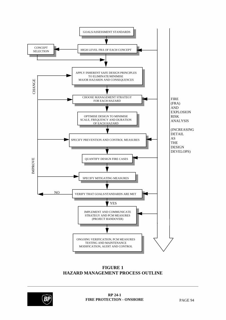
RP 24-1FIRE PROTECTION - ONSHORE PAGE 94
CONCEPTSELECTION
GOALS/ASSESSMENT STANDARDS
HIGH LEVEL FRA OF EACH CONCEPT
APPLY INHERENT SAFE DESIGN PRINCIPLESTO ELIMINATE/MINIMISE
MAJOR HAZARDS AND CONSEQUENCES
CHOOSE MANAGEMENT STRATEGYFOR EACH HAZARD
OPTIMISE DESIGN TO MINIMISESCALE, FREQUENCY AND DURATION
OF EACH HAZARD
SPECIFY PREVENTION AND CONTROL MEASURES
QUANTIFY DESIGN FIRE CASES
SPECIFY MITIGATING MEASURES
VERIFY THAT GOALS/STANDARDS ARE MET
IMPLEMENT AND COMMUNICATESTRATEGY AND PCM MEASURES
(PROJECT HANDOVER)
ONGOING VERIFICATION, PCM MEASURESTESTING AND MAINTENANCE
MODIFICATION, AUDIT AND CONTROL
YES
NO
IMPR
OV
EC
HA
NG
E
FIRE(FRA)AND EXPLOSIONRISKANALYSIS
(INCREASINGDETAILASTHE DESIGNDEVELOPS)
FIGURE 1HAZARD MANAGEMENT PROCESS OUTLINE

RP 24-1FIRE PROTECTION - ONSHORE PAGE 95
DEVELOP PROCESS AND LAYOUT OF ALLDESIGN CONCEPTS
INDENTIFY ALL MAJOR FIRE AND EXPLOSION (F&E) HAZARDS
COMPARE MAJOR F&E HAZARDS- SCALE, FREQUENCY AND IMPACT
SELECT CONCEPT OPTION
APPLY INHERENT SAFE DESIGN PRINCIPLESTO OPTIMISE LAYOUT & PROCESS OPTIONS
QUANTIFY HAZARDS: FREQUENCY, SCALE, INTENSITY & DURATION, TAKING INTO ACCOUNT INITIAL PREVENTION
& CONTROL PROVISIONS & SELECTED DESIGN CODES
VERIFY CONCEPT SELECTION (CSE)
RECOMMEND ADDITIONALPREVENTION/CONTROL MEASURES
CHANGE DESIGN CHANGE DESIGN
RECLASSIFYEVENTS
RECLASSIFYEVENTS
SELECT DESIGN AND EXTREMEACCIDENTAL EVENTS
SPECIFY ADDITIONALPREVENTIVE MEASURES
IMPROVE PERFORMANCE OFPREVENTIVE MEASURES
ASSESS FREQUENCY OF EVENTS& CONSEQUENCES AGAINST
COMPANY/LEGISLATIVE CRITERIA/ALARP
SPECIFY EXTRACONTROL
MEASURES
IMPROVEPERFORMANCE
OF CONTROLMEASURES
OPTIMISE DESIGN TO MINIMISEF&E DESIGN CASES
SPECIFY PERFORMANCE STANDARDSOF CONTROL MEASURES TO KEEP
F&E EVENTS WITHIN DESIGN CASES
QUANTIFY REMAINING OPTIMISEDDESIGN EVENTS TAKING INTO
ACCOUNT CONTROL MEASURES
ASSESS PRACTICALITY OF MITIGATINGAGAINST THE DESIGN EVENTS
OPTIMISE PREVENTION MEASURES FOR LARGEST/MOST-FREQUENT CASESTO SHEET 2
TO SHEET 2
FROM SHEET 2
IMPRACTICAL
DESIGN ACCIDENTALEVENTS (DAE)
EXTREME ACCIDENTALEVENTS (EAE)
INADEQUATE
FIGURE 2 (SHEET 1)HAZARD MANAGEMENT PROCESS DETAIL

RP 24-1FIRE PROTECTION - ONSHORE PAGE 96
UPDATE AND MODIFY THE PLAN FOR CHANGES IN:PROCESS DESIGNPROCESS OPERATIONMANAGEMENT STRUCTURE
IMPLEMENT THE FIRE AND EXPLOSIONHAZARD MANAGEMENT PLAN
FULLY DOCUMENT FIRE HAZARD MANAGEMENT PLAN SUPPORT DOCUMENTS INCLUDE:EVENTSCLASSIFICATION (DAE/EAE)PREVENTIVE MEASURESCONTROL MEASURESSTRATEGY FOR DAE: CONTROL/EXTINGUISH/EVACUATEDESCRIPTION/PLOT OF MAJOR DAE’S/EMERGENCY RESPONSE PLANSEXPOSED CRITICAL EQUIPMENTMITIGATING (PROTECTIVE) MEASURESPERFORMANCE STANDARDS FOR PREVENTION/CONTROL/MITIGATINGMEASURES, AVAILABILITY REQUIREMENTS/MAINTENANCE AND INSPECTIONFREQUENCIES AND PROCEDURESOPERATIONAL RESPONSIBILITIES/LIMITATIONSRESPONSIBLE PERSONS
DOES EAE FREQUENCY ANDCONSEQUENCES MEET LEGISLATIVE/
COMPANY CRITERIA AND ALARP
ASSESS, FREQUENCY OF AND TIME TO,ESCALATE TO EAE
(INITIATING EVENT & CONTROL OR MITIGATING MEASURE FAILURE FREQUENCY)
VERIFY ADEQUACY OF DESIGNSTANDARDS TO MATCH HAZARDS
SELECT AND SPECIFYPROTECTION/
REINFORCEMENT MEASURESTO MATCH HAZARDS
DECIDE IF EVENT IS TO BECONTAINED, EXTINGUISHED OR SUPPRESSED
IDENTIFY ALL CRITICALITEMS EXPOSED TO
F&E CONDITIONSWHICH COULD CAUSE FAILURE IMPROVE SYSTEM
PERFORMANCEOR SPECIFY
NEW SYSTEMSSELECT AND SETPERFORMANCE MEASURES
FOR ENSURING POSTEXTINGUISHMENT SECURITY
SELECT AND SETPERFORMANCE STANDARDS
OF SUPPRESSION/EXTINGUISHING MEASURES
REDUCE FREQUENCY OFINITIATING EVENTS
(IMPROVE PREVENTIONMEASURES)
FROM SHEET 1TO SHEET 1
INADEQUATE
CONTAIN SUPPRESS/EXTINGUISH
FROM SHEET 1
NO
FIGURE 2 (SHEET 2)HAZARD MANAGEMENT PROCESS DETAIL

RP 24-1FIRE PROTECTION - ONSHORE PAGE 97
NOTES:
1. FIRE PROOFING REGARDLESS 4. FIRE PROOFING KNEE OR DIAGONALOF ELEVATION ABOVE GRADE BRACING WHICH SUPPORTS VERTICAL LOAD
2. FIRE PROOFING ALL LEVELS 5. FIRE PROOFING REACTORBELOW FIRE POTENTIAL EQUIPMENT SKIRT, BRACKETS, OR LUGS
3. NO FIRE PROOFING ON BRACINGWHICH IS NOT LOAD BEARING
NON-FIRE POTENTIALEQUIPMENT =
FIRE PROOFING INDICATED THUS FIRE POTENTIAL EQUIPMENT =
FIGURE 3FIRE PROOFING OF STRUCTURAL STEELWORK
SUPPORTING FIRE POTENTIAL EQUIPMENT

RP 24-1FIRE PROTECTION - ONSHORE PAGE 98
FIGURE 4FIRE PROOFING OF STRUCTURAL STEELWORK SUPPORTING
FIRE POTENTIAL EQUIPMENT AND NON-FIRE POTENTIAL EQUIPMENT
NOTES:
1. NO FIRE PROOFING ON BRACING WHICH IS NOT LOAD BEARING.
2. FLOOR ON WHICH LIQUIDS CAN ACCUMULATE
NON-FIRE POTENTIALEQUIPMENT =
FIRE PROOFING INDICATED THUS FIRE POTENTIAL EQUIPMENT =
FIGURE 5FIRE PROOFING OF STRUCTURAL STEELWORK SUPPORTING
NON-FIRE POTENTIAL EQUIPMENT

RP 24-1FIRE PROTECTION - ONSHORE PAGE 99
FIGURE 6FIRE PROOFING OF PIPE RACKS WITH LARGE FIRE POTENTIAL
PUMPS INSTALLED BENEATHNOTES:
1. FIRE PROOFING KNEE OR DIAGONAL BRACING WHICH SUPPORTS VERTICAL LOAD.
NON-FIRE POTENTIALEQUIPMENT =
FIRE PROOFING INDICATED THUS FIRE POTENTIAL EQUIPMENT =
FIGURE 7FIRE PROOFING OF PIPE RACKS WITHOUT PUMPS BENEATH

RP 24-1FIRE PROTECTION - ONSHORE PAGE 100
NOTES1. NO FIRE PROOFING ON STRINGER BEAMS THAT
DO NOT SUPPORT VERTICAL LOADS.
2. FIRE PROOFING ON STRINGER BEAMS THAT DOSUPPORT VERTICAL LOADS.
NON-FIRE POTENTIALEQUIPMENT =
FIRE PROOFING INDICATED THUS:
FIGURE 8FIRE PROOFING OF STRUCTURAL STEELWORK SUPPORTING AIR COOLERS

RP 24-1FIRE PROTECTION - ONSHORE PAGE 101
NOTES
1. FIRE PROOFING ON KNEE BRACING
FIRE PROOFING INDICATED THUS: ______
FIGURE 9FIRE PROOFING OF TRANSFER LINE SUPPORTS

RP 24-1FIRE PROTECTION - ONSHORE PAGE 102
FIGURE 10GENERAL ARRANGEMENT OF STEAM LANCE, HOSE AND SUPPORT

RP 24-1FIRE PROTECTION - ONSHORE PAGE 103
*THESE DIMENSIONS MAY SEE FIGURE 10 FOR CENTRAL BE MODIFIED TO SUIT ARRANGEMENTS OF LANCE LOCAL REQUIREMENTS HOSE AND SUPPORT
FIGURE 11TYPICAL PROCESS STEAM LANCE

RP
24-1F
IRE
PR
OT
EC
TIO
N - O
NSH
OR
EPA
GE
104
FIG
UR
E 12
TY
PIC
AL
AR
RA
NG
EM
EN
T O
F SE
MI F
IXE
D T
OP
FO
AM
PO
UR
ER
ST
O F
LO
AT
ING
RO
OF
TA
NK

RP 24-1FIRE PROTECTION - ONSHORE PAGE 105
APPENDIX A
DEFINITIONS AND ABBREVIATIONS
Definitions
Standardised definitions may be found in the BP Group RPSEs Introductory Volume.
Client The organisation for whom fire protection facilities areprovided. Within BP this can be a Business, anAssociate or an Operating Unit.
Operator The organisation responsible for safe operation of theClient's plant. Within BP this would be an OperatingUnit.
Active Fire Protection: The equipment, systems and methods required for thedetection, alarming, control and extinguishing of firesusing water, steam, dry powder or gaseousextinguishants. An example of this would comprisedetection equipment for fire, smoke, gas or heat whichwill activate fixed extinguishing or control systems.
Passive Fire Protection: The provision of non-combustible materials which in afire will, for a defined period of time, protect equipment,prevent the collapse of structural supports or limit thespread of fire. In addition, passive systems embrace thebasic requirements for area separation and classification.
Essential Use Halon use shall be defined as essential in existing andfuture facilities where halons afford genuine protectionfrom a significant risk of:-
(a) loss of human life(b) traumatic injury(c) hazard to health e.g., toxicological effects of
alternative agents, or(d) damage to the environment, e.g. due to a major
catastrophe.
and other means of protection (e.g. alternative systems,deleted systems, alternative agents) would increase theabove risks or combination of risks to an unacceptablelevel.

RP 24-1FIRE PROTECTION - ONSHORE PAGE 106
Additionally, international, regional, national or statelaws, regulations, etc. may demand that protectionsystems be installed for other reasons which cannot befulfilled except through the use of halon systems (e.g.protection of equipment, materials, operations orinstallations of vital national interest).
Fire Exposed Envelope: The space into which fire potential equipment canrelease combustible fluids that can cause substantial firedamage.
Unless otherwise determined, a fire exposed envelopeshall be considered as extending between 6 and 9 mhorizontally and between 9 and 12 m vertically from thesource of liquid fuel.
Fire Rating: The fire resistance performance of the fire protection interms of fire type, time and temperature. This is usuallyHydrocarbon (H) or Cellulosic (A) rating.
Fire Resistance: The ability to resist fire for a given time when testedunder defined conditions.
Fire Potential : Applicable to plant and equipment (but excludingpipework) which contain combustible fluids (See API2218).
Fire Proofing: Materials or application of materials to provide a degreeof fire resistance to protect substrates.
Fixed Systems: See section 17.4.1.
Flammable Liquid Any liquid having a flash point below 37.8°C and avapour pressure not exceeding 2.76 bar abs at 37.8°C.
Hydrocarbon Risk Area: An area in which there is plant, equipment or storagecontaining hydrocarbon liquids, vapours or gases whichmay feasibly be released. These include crude oil, fuels,produced fluids, and utility fluids such as seal andlubrication oils, where their flash point requires that theybe protected.
Integrated Safe Design: The incorporation of design safety features on an inter-disciplinary basis, encouraging a co-ordinated approachto safety in the overall design process.

RP 24-1FIRE PROTECTION - ONSHORE PAGE 107
Petroleum Liquids: Defined in IP Model Codes of Safe Practice.
Class 0: Ethane, Ethylene, propylene, LPG and LNG.
Class I: Liquids which have a flashpoint below 21°C.
Class II: Liquids which have a flashpoint from 21°C to 55°C inclusive.
Class III: Liquids which have a flashpoint above 55°C up to and including 100°C.
Class II or III liquids can be further subdivided. ClassII(1) or III(1) liquids are those which are handled belowtheir flashpoints. Class II(2) or III(2) liquids are thosewhich are handled at or above their flashpoints.
Unclassified Liquids: Liquids which have a flashpoint above 100°C.
Protectability: The extent to which a given system lends itself toefficient protection by active/passive fire protectionmethods.
Portable Systems: Systems whose components can be transported by handor by tractor and used without need for mechanicalhandling equipment.
Radiant Heat Output: The heat energy radiated from a fire (kW).
Semi Fixed Systems: See section 17.4.1.
Source of Release: Any Continuous, Primary or Secondary grade source ofrelease as defined in BP Group RP 44-6, i.e. a pointfrom which flammable gas, vapour or liquid can bereleased into the atmosphere.
Abbreviations
AFFF Aqueous film forming foamALARP As low as reasonably practicalAPI American Petroleum InstituteASTM American Society for Testing and MaterialsBLEVE Boiling liquid expanding vapour explosionBS British StandardCBA Cost benefit analysis

RP 24-1FIRE PROTECTION - ONSHORE PAGE 108
CDP Computer data processingCO2 Carbon dioxideCSE Concept safety evaluationDAE Design accidental eventDEn Department of Energy (UK)DNV Det Norske VeritasEAE Extreme accidental eventESD Emergency shutdownF&E Fire and explosionFEHMP Fire and explosion hazard management planFFFP Film forming fluoroproteinFMEA Fault free and failure modes and effects analysisFP FluoroproteinFRA Fire Risk AnalysisGRP Glass reinforced plasticHAZID Hazard identificationHAZOP Hazard and operabilityHVAC Heating, ventilating and air conditioningIP Institute of PetroleumLNG Liquefied natural gasLPG Liquefied petroleum gasNFPA National Fire Protection AssociationNPS Nominal pipe size (inches)NPSHA Net positive suction head availableP&ID Piping and instrument diagramPCM Prevention, control and mitigationQRA Quantitative risk assessmentRHO Radiant heat outputUL Underwriter's LaboratoryVLCC Very large crude carrier

RP 24-1FIRE PROTECTION - ONSHORE PAGE 109
APPENDIX B
LIST OF REFERENCED DOCUMENTS
A reference invokes the latest published issue or amendment unless stated otherwise.
Referenced standards may be replaced by equivalent standards that are internationally orotherwise recognised provided that it can be shown to the satisfaction of the purchaser'sprofessional engineer that they meet or exceed the requirements of the referenced standards.
ANSI B31.3 Chemical Plant and Petroleum Refinery Piping
API 2218 Fire proofing practices in petroleum and petrochemicalprocessing plants
ASTM C150 Specification for portland cement
ASTM E119 Method for fire tests of building construction and materials
ASTM G26 Recommended practice for operating light-exposure apparatus(xenon-arc type) with an without water for exposure of non-metallic materials
BS 476 Fire tests on building materials and structuresPart 5 - Method of test for ignitabilityPart 8 - Test methods and criteria for the fire resistance ofelements of building construction
BS 5306 Fire extinguishing installations and equipment on premisesPart 2 - Specification for sprinkler systemsPart 4 - Specification for carbon dioxide systems
BS 5950 Structural use of steelwork in building.Part 8 - Code of practice for fire resistant design
BS 8110 Structural use of concretePart 1 - Code of practice for design and construction
D En Hydrocarbon fire resistance tests for elements of constructionfor Offshore Installations
- Test specification- Test procedure
IP Model code of safe practice in the petroleum industry. Part 9

RP 24-1FIRE PROTECTION - ONSHORE PAGE 110
Montreal Protocol Montreal Protocol Assessment II of the Halons TechnicalOptions Committee.
NFPA 11 Foam extinguishing systemsNFPA 12 Carbon dioxide extinguishing systemsNFPA 13 Installation of sprinkler systemsNFPA 15 Water spray fixed systems for fire protectionNFPA 16 Deluge foam-water sprinkler and spray systemsNFPA 17 Dry chemical extinguishing systemsNFPA 20 Centrifugal fire pumpsNFPA 24 Service mains and their appurtenances, privateNFPA 30 Flammable and combustible liquids codeNFPA 86 Ovens and furnacesNFPA 101 Life Safety Code.
Steel Construction Interim guidance notes for the design and protectionInstitute of topside structures against explosion and fire.
Fire and blast information group - updates.
UL 263 Fire Tests of Building Construction and MaterialsUL 1709 Standard for Safety Rapid Rise Fire Tests of Protection
Materials for Structural Steel.
BP Group RP 4-1 Drainage Systems(replaces BP CP 6)
BP Group RP 4-6 Procedure for the design of Buildings Subject to Blast Loading(replaces Appendix B of BP CP 19)
BP Group RP 12-4 Power System Protection and Control(replaces BP CP 17, Part 4)
BP Group RP 24-2 Fire Protection - Offshore(replaces BP CP 15 and BP CP 16)
BP Group RP 30-5 Instrumentation and Control - Selection and Use of Equipmentfor Instrument Protection Systems(replaces BP CP 18, Part 5)
BP Group RP 30-7 Design Philosophy for Fire and Gas Detection and ControlSystems
BP Group RP 42-1 Piping Systems(replaces BP CP 12)
BP Group RP 44-1 Overpressure Protection

RP 24-1FIRE PROTECTION - ONSHORE PAGE 111
(replaces BP CP 14)
BP Group RP 44-6 Area Classification(replaces BP CP 39)
BP Group RP 44-7 Plant Layout(replaces BP CP 3)
BP Group RP 52-1 Thermal Insulation(replaces BP CP 13)
BP Group RP 62-1 Guide to Valve Selection
BP Group GS 106-1 Cement-Mortar Lined Pipe(replaces BP Std 106)
BP Group GS 106-2 Painting of Metal Surfaces(replaces BP Std 141)
BP Group GS 124-1 Fire Pumps and Drives(replaces BP Std 217)
BP Group GS 158-2 Vertical Storage Tanks for Non-Refrigerated Liquids - Tanks toBS 2654(replaces BP Std 163, Part 1)
BP Group GS 162-1 Steel Wedge Gate, Globe and Check Valves.(replaces BP Std 150).
BP Group GN 91/16 Risk Based Approach to Tank Layout(issued by Corporate Safety Services)
BP Group GN 91/17 Fires in Petroleum Storage Tanks(issued by Corporate Safety Services)