
6500 - Robert H. Wager Co. Inc. - Home Page · The Model 6500 Smoke Meter can be used on any diesel...
29
34 2 3 4 5 FAX: +336 969-6375 Email: [email protected] Homepage:www.wagerusa.com USA: 1-800-562-7024 CANADA: 1-800-655-5585 Telephone: +336 969-6909 Robert H. Wager Co., Inc. 570 Montroyal Road, Rural Hall, NC 27045 SMOKE METER OPERATION MANUAL 6500
Transcript of 6500 - Robert H. Wager Co. Inc. - Home Page · The Model 6500 Smoke Meter can be used on any diesel...

3 4
2
3
4
5
FAX: +336 969-6375Email: [email protected]
Homepage:www.wagerusa.com
USA: 1-800-562-7024CANADA: 1-800-655-5585Telephone: +336 969-6909
Robert H. Wager Co., Inc.570 Montroyal Road, Rural Hall, NC 27045
SMOKE METER OPERATION MANUAL
6500

6500TABLE OF CONTENT
2
3
4
5
WARRANTY INFORMATION.................................................................................................................
GENERAL..............................................................................................................................................
QUICK START INSTRUCTIONS............................................................................................................
SYSTEM DESCRIPTION.......................................................................................................................
TECHNICAL SPECIFICATIONS............................................................................................................
SET-UP FOR TESTING.........................................................................................................................
SNAP ACCELERATION TEST...............................................................................................................
PERFORMING A SNAP ACCELERATION TEST..................................................................................
INTERFACE SOFTWARE.....................................................................................................................
APPENDIX A- MAINTENANCE.............................................................................................................
APPENDIX B- VERIFICATION WITH NEUTRAL DENSITY FILTER...................................................
APPENDIX C- TROUBLE SHOOTING.................................................................................................
APPENDIX D- SPECIFICATIONS.........................................................................................................
APPENDIX E- DEFINITIONS.................................................................................................................
APPENDIX F- PRINTER MANUAL........................................................................................................
APPENDIX G- CONFIGURING CONTROL UNIT...................................................................................
1
2
3
4
7
8
9
10
14
16
17
18
20
21
22
25

Seller expressly warrants to Buyer (a) that the equipment will comply with thedescription set forth herein; (b) that the components and parts fabricated by Seller willbe free from detrimental defects in workmanship and materials.
If it appears within one year from date of shipment by Seller that the equipment doesnot meet these express warranties and Buyer gives Seller prompt and reasonablenotice, Seller shall, at its option, either repair or replace at its expense, F.O.B. Seller’sworks, but not dismantle or reinstall, the defective parts provided, upon request suchparts are shipped freight prepaid to Seller’s works.
These warranties shall not apply if equipment is subjected to other than normal andproper storage, handling, installation, operation and maintenance or to unauthorizedrepairs or alterations. Equipment, components and accessories made by othermanufacturers are warranted only to the extent of the original manufacturer’s warrantiesto Seller.
The foregoing warranty obligation of the seller shall constitute the sole and exclusiveremedy of the buyer and the sole liability of the seller, except as set forth herein andexcept as to the title it is expressly agreed (a) that there is no warranty ofmerchantability of any other warranty, express, implied or statutory, nor any affirmationof fact or promises by Seller with respect to the equipment or parts or otherwise whichextend beyond the specifications mutually agreed upon in writing by Seller and Buyer,and (b) that the Buyer acknowledges that it is purchasing the equipment solely on thebasis of the commitments of Seller expressly set forth herein, in no event shall Seller beliable for special, indirect, or consequential damages including, without limitation,anticipate profits..
WARRANTY
1
6500

2
6500GENERAL
The WAGER Model 6500 Smoke Meter is in full compliance with the requirements ofthe SAE J1667 test criteria—the current U.S. standard.The software supplied with you unit(s) (V5.1 or above) allows the user to apply thealgorithm for ambient conditions (see SAE J1667 document, Appendix B) to convert saved opacity data.The meter's simple design and portability makes it easy to obtain accuratemeasurements. It provides an accurate means (± 1%) of detecting and measuring theopacity of smoke emitted by a diesel engine.The use of the Model 6500 Smoke Meter promotes combustion efficiency for fueleconomy and ensures compliance with diesel emission standards set by environmentalair quality codes.The program document for SAE J1667 is Surface Vehicle Recommended Practice. Itcan be obtained from:
SAE International400 Commonwealth DriveWarrendale, PA 15096-0001 Telephone: 724/776-4970
Or electronically at: http://www.arb.ca.gov/enf/hdvip/ccdet/saej1667.htm
It is also part of the Heavy-Duty Vehicle Inspection Program Periodic Smoke InspectionProgram issued by the Mobile Source Operation Division, California EnvironmentalProtection Agency, Air Resources Board. One copy can by downloaded free of chargefrom: http://www.arb.ca.gov/enf/hdvip/ccdet/saej1667.htmWeather data for each individual city can be obtained by•Use of an inexpensive desk-top weather station•Call to a local radio or television station•Internet through http://www.weather.com (or a number of other locations)

3
6500QUICK START INSTRUCTIONS
*Disclaimer*Operator must use caution when working around a hot stack. Protective gloves are required.
If you chose not to use the extension pole, please be advised that the installation and/or attachment of the sensor head manually is not recommended.
Manual installation, which may require the operator to use a ladder, climb upon the equipment being tested, or any other unsafe maneuver, constitutes a waiver of liability for any and all personal injury sustained by the operator in the use of this equipment.
Robert H. Wager Co., Inc. does not warrant, guarantee or insure the safety of any person or persons not in compliance with this instruction manual.
It is important that the tester is familiar with the safe operation, features, and maintenance of this unit as well as the
SAE J1667 document.
To give you the opportunity to test the unit when it is received, we have prepared the following:
Press SAVE.
Take the sensor head and the control unit out of the carrying case.
1
Connect the sensor head to the control unit’s mating receptacle (lock into place by turning the locking ring • turn clockwise)
2Press the ON/OFF switch to activate the unit. It automatically performs self-calibration.
3Select the stack size by pressing the button until your
measurement appears.
4
Pass your hand through the light path until unit displays 100%. Remove your hand to cycle to 0%.
6The Horsepower shown is the default setting. If it does not agree with your engine’s specifications, press SELECT until the correct HP range is shown.
Press SAVE.
5
Attach the sensor head as described in the SAE J1667 booklet (be sure to observe all safety regulations shown later in this manual).
8
If it does not show “0” (zero) press the ZERO button.
7 7cm
6500SYSTEM DESCRIPTION
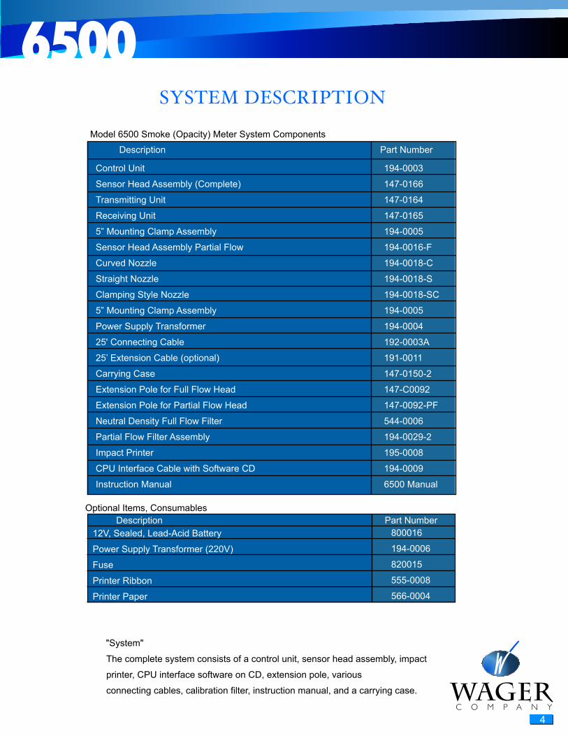
Control Unit
Sensor Head Assembly (Complete)
Transmitting Unit
Receiving Unit
5” Mounting Clamp Assembly
Sensor Head Assembly Partial Flow
Curved Nozzle
Straight Nozzle
Clamping Style Nozzle
5” Mounting Clamp Assembly
Power Supply Transformer
25' Connecting Cable
25’ Extension Cable (optional)
Carrying Case
Extension Pole for Full Flow Head
Extension Pole for Partial Flow Head
Neutral Density Full Flow Filter
Partial Flow Filter Assembly
Impact Printer
CPU Interface Cable with Software CD
Instruction Manual
194-0003
147-0166
147-0164
147-0165
194-0005
194-0016-F
194-0018-C
194-0018-S
194-0018-SC
194-0005
194-0004
192-0003A
191-0011
147-0150-2
147-C0092
147-0092-PF
544-0006
194-0029-2
195-0008
194-0009
6500 Manual
Description Part Number
Model 6500 Smoke (Opacity) Meter System Components
12V, Sealed, Lead-Acid Battery
Power Supply Transformer (220V)
Fuse
Printer Ribbon
Printer Paper
800016
194-0006
820015
555-0008
566-0004
Description Part Number Optional Items, Consumables
The complete system consists of a control unit, sensor head assembly, impact
printer, CPU interface software on CD, extension pole, various
connecting cables, calibration filter, instruction manual, and a carrying case.
"System"
4

6500
5
Full Flow Sensor Head Assembly
The sensor head assembly is attached to the vehicle exhaust in accordance
with the criteria in the SAE J1667 document. (The document describes the
different stack configurations and the placement of the sensor head).
Cable
The connecting cable is 25 feet long. Optional lengths of up to 50 foot are
available.
Control Unit
The control unit is operated by a membrane keypad, which consists of eight
tactile feedback push buttons.
The display is an alphanumeric LCD, containing 16 characters by two rows. In
low light situations, the display can be backlit. The display shows the prompts
the operator follows throughout the test sequence(s).
Up to 100 test can be stored in the system’s memory.
The RS232 connection permits an interface to a printer or CPU. The banana
jacks (red and black) allow a 0 –1 VDC output for a chart recorder.
Power
The meter is shipped with an AC Adapter/Charger which operates in 110V
(220V Export Version).
The 12 V sealed, lead-acid cell battery will allow up to 40 hours of
continuous operation with a full charge. This is reduced to about 20 hours, if
the display is backlit.
The time-out feature will turn the unit off automatically if none of the front
panel buttons are pressed for 20 minutes.
(See Appendix F to set this feature).

6500
6
Partial Flow Filter Assembly
To assure continuous accuracy, the .2 Neutral Density Filter is supplied with the
system. We recommend a check before and after the day’s testing.
Extension Pole
An extension pole is supplied with each system to allow the operator to attach
the sensor head to the stack from the ground.
Carrying Case
All the system’s components, except the extension pole, can be fitted into the
plastic carrying case. Foam inserts are specially molded to fit the components
and protect the electronics.

6500
7
The Wager Model 6500 Smoke Meter meets SAE J1667 specification for full flowmeters.
AccuracyThe unit’s accuracy is + OR - 1.0% nominal one digit. The control unit is initiallycalibrated under clear stack conditions with checks at 0% and 100% opacity.The accuracy of the unit is verified by use of the .2 neutral density filter supplied with the system.
Ambient ConditionsThe unit operates in 32° to 120° F (0° to 50° C).
Once the test has been performed use the Ambient Correction Calculator enclosed on the software CD to convert the test results.
ND filter provided for measurement verification.
ReliabilityZero stability at less than 1% drift per use.The pulsed green LED has infinite life expectancy.Check filter provided for easy calibrationAll solid state electronics.Manufactured by an ISO 9002 company.
ApplicationsThe Model 6500 Smoke Meter can be used on any diesel engine, with primaryapplication in testing trucks, busses, and cars.
Contact WAGER for special applications, such as stand-by power, miningoperations, railroad use, boating/maritime, industrial, etc.
Functional Description
When the unit is activated, the transmitter emits a light beam at a knownintensity. As the light passes through the smoke plume, some or all the light isdiverted.The sensor head consists of two components, a light source (transmitter) and alight detector (receiver).The light detector measures the amount of light received, and compares thiswith the amount of light being emitted. The difference between the two values isopacity.
TECHNICAL SPECIFICATIONS

6500
8
SET�UP FOR TESTING
Installation of Sensor Head(s)
Full Flow Sensor Head
Position the sensor head over the top of the exhaust stack with the extension handle. The
hook attachment will aid the operator on the ground to visually aid in the placement of the
head and the strong magnet clamp keeps the position without effort. Adjust the angle and
position of the sensor head assembly as described in the SAE J1667 document.
Partial Flow Sensor Head
Attachment of the partial flow head depends on the shape of the
stack. Three nozzles are provide with the system: curved, straight,
and clamping styles. The baynet (straight) nozzle hooks over the
straight stack. The curved nozzle has a stop that allows correct
positioning. The unit is held with strong magnets, which are part of
the extension pole assembly.
Attachment of Connecting Cables
The connecting cable is attached to the control unit and the sensor head assembly by means of "MultiMate" connectors.
The ends of the cable have connectors that will fit into matching grooved receptacles. Align the pins on a connector with
the holes on its mating receptacle. Insert the connector into its mating receptacle. Lock the connector in place by
screwing the locking ring clockwise until a firm connection is made. Repeat these steps for the second connector.

6500
9
SNAP ACCELERATION TEST
The Model 6500 Smoke Meter has been designed in accordance with the specifications of SAE J1667.
The meter will prompt the operator through the required three test sequence compute the average and the “spread”. However, the operator must be familiar with the document to make the determination if the test(s) meet the SAE J1667 and/or the individual state’s (province’s) test requirements.
Important:To assure continuous accuracy of the test performed, a .2 Neutral Density Filter is provided with the system. Refer to appendix B for the description of this procedure. Once the verification check has been complete, return the filter to the protective sleeve.
The filter should be stored inside the case or protective sleeve to keep the sun from deteriorating the tint of the filter. If the filter glass is left out in the sun for an extended period of time, the UV light will reduce the opacity of the tint your filter may read lower then stated. If your filter glass is reading higher than normal, the filter may need cleaning with a clean dry cloth.
Note: The filter’s optical properties change with exposure to light and over time.Filters will have to be replaced periodically.

6500
1 0
SNAP ACCELERATION TEST
Bring your engine to operating temperature and turn off
1 2
The opacity meter is factory set in the test series mode. (snap acceleration testing). To switch to the follow mode ( real life opacity readings) You must press the ZERO button immediately.
3 4
Attach the sensor head as described in the SAE J1667 booklet (www.sae.org).
97cm
Make certain the sensor head is clear of any obstructions.
7
Block the light path (with your hand) The result is a reading of 100%. Remove your hand and check that the result is 0.0%,
8
If it does not show "0" (zero) press the ZERO button.
5
To set the exhaust stack size of your vehicle, press the SELECT button until your measurement appears,(2" through 5") If you are using a partial flow sensor head you must always select a 5" exhaust stack size. Press Save.
The HP displayed is the default horsepower rating for the selected size. If it agrees with your engine’s specifications, press SAVE. If not press select until the correct rating appears. Then press save.
6
11
The display will give you the prompt START TEST and indicate T1= for the first test to be performed.
Press SAVE
13 14
The unit will display T2= and START TEST. Press START TEST and repeat steps 12 and 13. Press SAVE.
15
COMPUTEAVERAGE
The three tests must be within 5% of each other for the test to be considered valid. This is shown as "Spread" on the test result. You may then press the COMPUTE AVERAGE button.
16
With the engine in Neutral gear or in Park, rapidly accelerate the engine for four to five seconds. Return to idle (The display will show the current opacity readings and the peak value reached during the test).
12
After selecting the mode, the unit automatically performs a self calibration.
10
Start your engine.
The unit will display T3= and START TEST. Press START TEST and repeat steps 12 and 13 again. Press SAVE.
18
Connect the impact printer and turn on by pressing "1" (the number one) and press PRINT on the control unit.
19
Turn the unit off
Save to store test record into memory.
17

6500
11
Remove the sensor head from the stack. Use extreme caution when working around a hot stack.
The tests are numbered sequentially. If the test is printed later, note the number of the record with the vehicle identification. Up to one hundred tests can be saved, until the memory has to be cleared. (See Appendix C for instructions on clearing tests from memory).
Printer Operation
Connect the printer to the control unit’s RS232 port. Press “1” (number one) on the printer to turn it on.
You can print any test by pressing the PRINT button either before you save the test, immediately after the test, or at a later time. You may print the same test as often as you require.
(Printing stored test at a later time is described in detail under “Printing Saved Tests” later in this section.)
The printed test strip includes:Record numberDate and time of the testStack size and horsepower ratingsPeak values of the three tests in percentageAverage of the three testsSpreadPass/Fail
In addition, the printer strip allows for addition of the VIN number and the operator’s signature.
Note:If the memory holds 100 tests (maximum), the control unit will automatically enter the PRINT mode when you turn the unit on. You have the option to delete test(s) before you can perform another test. This prevents you from performing a test that cannot be saved. A description of the software download and data management is listed in the“Software” section of this manual.

6500
1 2
Installation for Rolling Test
Undo the clamp bolt and nut and remove the extension handle. The magnetic clamp assembly will also separate from sensor head.
Reinstall the magnetic clamp assembly directly to the sensor head.
If the exhaust stack is equipped with an exhaust flapper, remove the flapper cover assembly. If this is not practical, tighten the hinge bolt on the flapper cover assembly to maintain the flapper in its maximum open position.
Install sensor head assembly on exhaust stack, using the magnetic clamp assembly. (See above and SAE J1667 document for instructions). Secure the unit with locking pin.
For actual road tests, you may need to adjust the sensor head assembly, so that the measurement is not affected when the vehicle is in motion.
Follow Mode Test
The “Follow” mode provides a means of providing a continuous “real life” opacity reading and performing tests under load, either on the road or on a dynamometer.
Follow the instructions listed in Installation Sections for attaching the sensor head to the stack of the vehicle. Make a special point of securing the sensor head if a road test is performed.
Press the ON/OFF button on the control unit. The unit will perform a self-calibration.
Press the SELECT button until the desired stack size is displayed (factory default is 5”). Press the SAVE button.
The HP shown corresponds to the default horsepower. If your engine has different specifications, press SELECT until the correct value is displayed. Press SAVE.
Press the START TEST button.Follow your state’s test requirements as to RPM and load factors.
When you have reached the governed load, press SAVE.

6500
1 3
Note:Follow mode tests cannot be printed on the impact printer. However, the data can be captured using a data acquisition system or module from the red and black jacks on the side of the control unit. These red and black jacks output a 0 to 1 volt DC which corresponds to 0 – 100 percent opacity.
Printing Saved Tests
The WAGER Digital Smoke Meter Model 6500 can save up to 100 tests. After thememory is full, you have the following options:•Print test(s) and delete•Download to a CPU and delete (Download to a CPU is covered in the “Software” section)
To print, connect the printer cable to the control unit’s RS232 (printer) port. Press “1” (number one) button on your printer.
On the control unit, press and hold the PRINT button and then touch the ON/OFF button.
The unit will display number of the last test performed. Press SELECT to scroll to the record number you want to print. Press PRINT when you have reached the test.
To delete test from memory, press ZERO button.
Chart Recorder (Optional)
The WAGER Model 6500 Smoke Meter outputs a 0 – 1 V signal through the banana jacks (located next to the AC power input plug).
The output voltage reflects the opacity output where 0 V is 0 % opacity and 1 V = 100% opacity. Refer to the chart recorder’s documentation for instructions. Printing To Other Printers You may use any serial printer using the following serial protocol:
See your printer's documentation for instructions on configuring to match these settings.
Baud Rate Data Bits Stop Bits
9600 8 1

6500
1 4
INTERFACE SOFTWAREThe proprietary software was written specifically to simplify the process of extracting smoke opacity data from the Wager 6500 Smoke Meter to the customer’s hard drive. In addition, it provides a graphic interface of the test sequence. The operator must be familiar with the operation of the Model 6500.
Print to PC software version 5.1.
This version will work on windows xp, vista, and win7. Install the software from the cd or electronic image by clicking setup file. The software will ask you a few questions. Agree to the license and then use the default setting for all other questions.Once the software is installed on your computer, double click the “6500 PC Interface” icon.Upon the opening of the software, you must configure it to run on your computer. Click print to pc, and then select configuration. In the configuration screen, enter your (or your customers) information. Now on the bottom left, select the com port number that you have the interface cable connect to on the back of your desktop. If you are using a laptop, set the com port number to the usb to serial adapter that you have installed. Note : if this number is not set to match the physical com port, then the communication between the pc and the 6500 control unit will not function.Once you have the configuration set to your desired setting, click save and click replace to complete the configuration.Now that you have set up the software, you will want to operate it. Click print to pc and click print to pc to ensure the check mark is visible. Now connect the 6500 control unit to the pc via the cable, turn the control unit on and immediately press print. The control unit will come to the first record. If this is not the record you wish to print, press select to scroll through the records until you find the record you want to print.
THIS SOFTWARE AND THE ACCOMPANYING FILES ARE SOLD "AS IS" AND WITHOUT WARRANTIES AS TO PERFORMANCE OR MERCHANTABILITY OR ANY OTHER WARRANTIES WHETHER EXPRESSED OR IMPLIED.
In particular, because of the various hardware and software environments into which WAGER65 may be put, NO WARRANTY OF FITNESS FOR A PARTICULAR TEST IN ANY COUNTRY, STATE OR OTHER GOVERNMENTAL AGENCY IS OFFERED.
Good data management procedures dictates that any program be thoroughly tested with non-critical data before relying on it. The user must assume the entire risk of using the program. ANY LIABILITY OF THE SELLER WILL BE LIMITED EXCLUSIVELY TO PRODUCTREPLACEMENT OF ORIGINAL DISKS.

6500
1 5
Note : place a check mark in the test passed box if the vehicle has pass, leave it blank if the vehicle failed.Once you enter the vehicle information and checked/unchecked test passed, click ok. Lastly, click save if everything is correct on the displayed test report.You can print the report by clicking print. This will only print the displayed record. If you wish to print other reports, click print to pc and then click print to pc viewer. Use the up/down arrows to scroll through the records until you find the report you wish to print. Once you find the desired report, click print.Note : there is an option for upload all tests. This will download all the test records that are store in the control unit in one action. It will not, however, give you the option to enter vehicle information, and is therefore not recommend for snap test usage.
Ambient Conditions CalculatorIncluded in the software is ambient conditions correction calculator. Once you are in this screen, enter all the pertinent data and the calculator with display the dew point and corrected opacity values. The SAE J1667 document contains guidelines for the acceptable ambient test conditions. The software, does allow input outside those guidelines:Ambient temperature: no range limit (F)Relative humidity 0 to 100%Barometric pressure no range limit (in-Hg)The program will not accept any input of humidity outside the range shown.
To exit the program from any screen, click the red X on the top right of the window..

6500
1 6
Battery Replacement
Remove the two screws and carefully lift off the top to expose the attached wires. Remove all four connectors from the front panel. Place the front panel aside.
Turn the unit over. Remove the four screws holding the battery bracket in place. Remove the two connectors from each end of the battery. Place the new battery back in the control unit with the terminal furthest away from the bottom of the enclosure. Fasten the battery bracket into place using the four screws. Re-attach the four front panel connectors. Replace the front panel the right and left screws.
Cleaning Lenses
To assure regular easy access to the lenses, we have provided two snap closures. The lenses can be wipes with a soft cloth.
We strongly recommend that a regular procedure of calibration and cleaning the lenses is established. During light use, a daily cleaning may be enough. During heavy testing, we recommend a frequent cleaning throughout the day.
To remove soot, dip soft cloth in denatured rubbing alcohol (make sure to let it dry) and rub gently over lenses.
In laboratory settings and heavy commercial use, please note that we have provided connectors for an external air purge.
Connecting Cables
Connecting cables are subject to wear, based on incorrect handling, abuse, and contact with a hot stack. Check, repair, and replace cables when their condition affects the operation of the smoke meter.
Printer
Please review the printer manual in Appendix F for instructions.
APPENDIX A. MAINTENANCE

6500
1 7
The Neutral Density Filter allows you to verify that that the system operates within the ± 1% tolerance.The purpose of this operation is to verify that your 6500 opacity meter is reading correctly. Each filter or system comes with a document stating its value. If you have two filters, then you should have two separate documents. If you order a replacement filter, ensure that you discard the old document. The document declares the stated value for the filter in opacity, the max and min measurement values, and is signed and dated from the factory.
There are two styles of filters: full flow and partial flow. The full flow filter is a 2” square piece of tinted glass. To measure the full flow filter, place the filter flush up against the metal circular baffle plate and center the glass over the hole that is emitting the green light. The partial flow filter is an aluminum bar with holes at either end. One of the holes contains the filter. To measure the partial flow filter, fully insert the bar, glass end first, into the small slot that is perpendicular to the channel where the smoke flows out of the top of the head.
Start with the meter off, and the filter placed off to the side. Turn the meter on, and select the default setting for stack size and horse power. When the meter displays “press start to begin test”, do not press start. Instead, position the filter as described above. Once the filter is positioned properly, press start. The meter will read the glass, then press save. Repeat this step three times. Next, press the compute average button. This average is compared to the stated value on the document. If the average is within the specified range, the meter is functioning properly and you can proceed to perform smoke measurements. If the average is outside the specified range, do not perform test and call tech support to diagnose the problem.
APPENDIX B. VERIFICATION WITH NEUTRAL DENSITY FILTER

6500
1 8
The WAGER Model 6500 Smoke Meter has been designed to be nearly trouble free for many years of use.
However, some components are subject to unintentional abuse, which is not covered in our warranty.
Sensor HeadAlways carry the sensor head assembly by the metal “yoke”. Dangling the sensor head assembly from the cable causes extreme stress and could lead to premature failure.
BatteryThe re-chargeable lead-acid battery can withstand many charges/discharges. They gradually lose their ability to hold a charge. Replace the battery when the shortened intervals interfere with your normal operation of the unit.
Power FailureIf the control unit will not power on, check to see if the battery is fully charged. If yes, check the fuse.
Error MessagesCABLE FAILURE DISCONNECTED? The light source is fully powered, but no light is detected receiver. This could be caused by several factors:
•The sensor head assembly cable is not connected to the control unit
•The light source in the sensor head assembly has failed.
•The connecting cable is malfunctioning.
Action:
Check to make sure that the cable is firmly attached to the unit. If another unit’s sensor head assembly and cable is available, try to see if this corrects the error.
If the message disappears, then you need to send in the sensor head assembly and/or cable for repair.Contact WAGER Technical Services for further instructions and/or return of the unit forrepair.
APPENDIX C. TROUBLE SHOOTING

6500
1 9
SENSOR FAILURE REQUIRES REPAIR
This indicates that the light source is functioning, but the receiver is not receiving the output.
A dirty lens on either the transmitter and/or the receiver side. Malfunction in the sensor head assembly or cable.
Action:Clean the lenses as described in “Maintenance” section. If this does not correct the problem, call WAGER Technical Services for assistance.
RECHARGE BATTERYThe battery is fully discharged. This message is displayed for a few seconds before the unit turns itself off.
Action:Recharge the battery or run the unit using the AC power adapter.
BATTERY LOW RECHARGE SOONThe battery is getting low and needs recharging.
Action:Recharge the battery or run the unit using the AC power adapter. (The unit will continue to function normally after displaying this message.)
MEMORY FULL DELETE TESTS FIRST
The unit saved 100 tests and has reached full storage capacity. Either you have saved 100 tests, or the unit has experienced some electrical shock that has reset the number of saved tests. The unit immediately goes into the Print and Delete Test Series mode after displaying this message.
Action:Use the ZERO to delete test series.
PRINTER NOT ATTACHEDThe unit could not find a printer attached to the serial port.
Action:Make sure both ends of the printer cable are firmly attached. Also make sure the printer is configured for serial operation (see documentation in Appendix F).

6500
2 0
Electrical Specifications
Mechanical Specifications
Performance Specifications
Light SourceLight Sensor
DisplayMeter Accuracy
Peak HoldRecorder Output
BatteryCharging Transformer
(Model AD-1880)
Led - Green Gallium Phosphide 570 NMSi Photo Diode with IR Filter
(Backlit) Liquid Crystal Display (LCD)1.0% Nominal, 10th digit
No Drift0-1 Volt or 0-1 MA
12V, 2.2 amp hour, sealed, lead acid cell
-+ -+
Size4" W x 8" D x 4" H
14" W x 10" D x 4" H
5" Through the Stack
Weight5.0 lb.3 lb.
w/o cables
Control UnitSensor Head
Stack Clamp Assembly
Range:Warm up Time:
Response Time/Display*Response Time (Chart Recorder
Output)Linearity
Zero Stability (Drift)Temperature Stability, Sensor Heads
Battery Life
Battery Life (night light on)
0.0% - 100.0% opacityNegligible
0.45 seconds for 0-90% opacity0.45 seconds for 0-90% opacity
1% from 0-100% opacityLess than 1% in 60 minutes
1% from 32 Degrees - 120 Degrees F40 hours; 1 hour after low batteryindication, 8 hours to full charge
half of the above
-+
-+
120 VAC 22 Watts in /18 VDC @800 MA out
APPENDIX D. SPECIFICATIONS

6500
2 1
APPENDIX E. DEFINITIONS
Follow Mode
A Configuration mode selectable item that allows the unit to continuously read opacity and maintain a “peak hold” reading. The alternate mode is Test Series Mode.
Opacity
The percentage of light transmitted from a source that is prevented from reaching a light detector.
Preliminary Snap Acceleration Test
A series of Snaps (usually at least 3) performed before testing begins to clear the exhaust system of residual particles.
Snap Acceleration Test
The engine is allowed to run at maximum RPM’s for 4 to 5 seconds and brought back to idle. Three “snaps” are taken for this test. Each individual test is stored and a mathematical formula applied to provide an “average.” See Page 14 for step-by-step instructions.
SAE J1667A document created to outline specifications to manufacturers of opacity meters, as well as test criteria for performance of opacity (smoke) readings.
Test Series ModeA Configuration mode selectable item that causes the Model 6500 to run a fixed series of Snap Acceleration Tests as dictated by the Society of Automotive Engineers (SAE) in specification J1667. The alternate mode is Follow Mode.
6500
2 2
APPENDIX F. PRINTER MANUAL
Please note that for safety reasons, the printer is shipped with no charge in the batteries.
RS232 Interface
Printers with an RS232 serial interface are fitted with a D25 socket. Connections to this socket are as follows:
Note that RTS is not implemented but pin 4 is pulled up to +10V via a 1 K ? resistor.
Power Supply
Internal Ni-Cad batteries. A supply of 9V DC unregulated or 12V regulated at 0.6 A (nominal) is sufficient to recharge the batteries.
An initial charge of approximately 20 minutes will be sufficient both to operate the printer and charge the batteries. The maximum on-load terminal voltage supplied to the printer must be limited to 12V. A full battery charge will take approximately 14 hours.
The printer incorporates a power saving feature, which turn the printer off after five minutes’ inactivity (user selectable). This feature may be disabled, if desired.
Power-On Procedure
Check the batteries are sufficiently charged or that the power supply is correctly fitted and operational.
Open the lid and ensure that paper and a ribbon are present and that there are no foreign objects inside the paper well or mechanism. Close the lid, ensuring that the paper passes through the paper exit slot. Switch on the printer by pressing the "1" on the switch panel. The power-on indicator will light and themechanism will reset.
FunctionTXRXCTSGNDDTR
DirectionOUTININ-OUT

6500
2 3
Paper Loading
If the paper roll needs replacing open the lid and remove the remaining paperusing the feed switch. Do not pull paper out of the rear of the mechanism. Reeloff a few inches from the new paper roll and check that the end is square. Seatthe new roll in the paper well with the paper emerging from the bottom of theroll.
Make sure the printer is on and offer the paper intothe back of the mechanism while pressing the feedswitch. Keep the feed switch depressed untilenough paper is fed out of the mechanism to passthrough the exit slot in the lid. Feed the page,through this slot and close the lid
Ribbon ChangeThe ribbon cassette will clip off on one sideand can be easily removed. After checkingthat the ribbon is taut, clip it into positionmaking sure that the paper still feedsbetween the ribbon and the cassette bodycorrectly. Wind the knob to take up anyslack in the ribbon. Close the lid ensuringthat the paper passes through its exit slot.
Paper FeedFor a single line paper feed press andrelease, the feed switch. For continuous linefeed keep the switch depressed
Default SettingsThe printer is supplied with the following default settings: Data bits 8 Parity None Baud Rate 9600 Character Set USA Print Mode Text Auto-Off 5 minutes Emulation 560
TURN WHEELIN DIRECTIONSHOWN TO WIND RIBBON
EJECT
PUSH THISEDGE TO EJECT CASSETTE
1
POWERLED
SETUP
FEED ON

6500
2 4
Self TestTo initiate self test press the power and feed switch together until the test starts.
This will check all the mechanics and a large proportion of the software and hardware (except that dealing with the data interface) without the need for connection to a host.
The software issue is printed in double height, double width text, followed by the character set in normal text and a list of the current settings of the user selectable options. If the settings are correct for your host you are ready to connect the printer to your system; otherwise you will need to reprogram the printer. The self-test is repeated until the power is switched off. Power on againfor normal operation.
This equipment has been tested and found to comply with the limits for a Class A digital device, pursuant to Part 15 of the FCC Rules. These limits are designed to provide reasonable protection against harmful interference when the equipment is operated in a commercial environment.
This equipment generates, uses and can radiate radio frequency energy and, if not installed and used in accordance with the instruction manual, this equipment may cause interference to radio communications.
Operation of this equipment in a residential area is likely to cause harmful interference, in which case the user will be required to correct the interference at his own expense.
If this equipment does cause interference to radio or television reception, which may be determined by turning the equipment off and on, the user is encouraged to correct the interference by one of the following measures:•Reorient or relocate the receiving aerial• Increase the separation between the equipment and the receiver• If the equipment is AC powered, connect to an outlet on a different circuit to that on which receiver is connected.•Consult your supplier or an experienced radio/TV technician for advice. Shielded cables must be used with this unit to ensure compliance with Class A FCC limits.
WARNING (Canada).
Changes or modifications to this unit not expressly approved by the manufacturer could void the users’ authority to operate the equipment
WARNING (USA)
This digital apparatus does not exceed the Class A limits for radio noise emissions from digital apparatus set out in the Radio Interference Regulations of the Canadian Department of Communications

6500
2 5
Configuration Mode
In the configuration mode, the user can change the following items in the control unit: Time including hour, minutes, and format (12 hour or 24 hour clock) •Date including month, day, year, and format (American or European) •Time-out battery saving feature •Reset to factory defaults •Print current configuration
To access the “Configuration Mode” turn on the unit and press ZERO and START TEST at the same time. Press these two buttons within 2 seconds.
The “Configuration” display will give you the following selections:
START TEST =exitSELECT=next,ZERO=changeSAVE=store.
Set Time:
Press the SELECT button. The LED displays the following:ZERO= set time XXXXX (your current time setting)
Press the ZERO for ”setting mode.”
Press ZERO to change time format (toggles between 12 and 24 hour clock).
Press the SELECT for “hour” mode.Press ZERO to scroll to your correct hour.
Press the SELECT for “minute 10’s digit mode. (12:00 a.m.)Press the ZERO to scroll to the correct minute 10’s digit.
Press the SELECT for “minute 1’s digit mode. (12:00 a.m.)Press the ZERO to scroll to the correct minute 1’s digit.
APPENDIX G. CONFIGURING CONTROL UNIT

6500
2 6
Set Date
Press SELECT twice.
Press ZERO for “set date” mode.
Press ZERO to change date format (toggles between the formats dd/mm andmm/dd).
Press SELECT to set month 10’s digit. (06-12-98)Press ZERO to scroll to your correct month 10’s digit.
Press SELECT to set month 1’s digit. (06-12-98)Press ZERO to scroll to your correct month 1’s digit.
Press SELECT to set day 10’s digit. (06-12-98)Press ZERO to scroll to your correct day 10’s digit.
Press SELECT to set day 1’s digit. (06-12-98)Press ZERO to scroll to your correct day 1’s digit.
Press SELECT to set year 10’s digit. (06-12-98)Press ZERO to scroll to your correct year 10’s digit.
Press SELECT to set year 1’s digit. (06-12-98)Press ZERO to scroll to your correct year 1’s digit.
Time-Out/Battery Saving FeaturePress SELECT three times for “Time Out” mode.
Press ZERO to change time out feature (toggles between enabled and disabled).
Reset Factory Default
Press SELECT four times for “reset” mode.
Press ZERO to reset factory defaults (as you received the unit from WAGER).
Press COMPUTE AVERAGE to confirm reset to factory default.
Print Configuration
Connect printer cable to control unit. Press “1” (figure one) on your printer toturn the unit on.

6500
2 7
Press SELECT five times for “Print Configuration” mode.
Press PRINT for configuration print out.
Exit Configuration Mode
Press START TEST to exit the configuration mode at any time. Any changes youhave made up to that point will be saved (become the default setting).


![[XLS] and Construction... · Web view36 6500 30 3000 9 36 6500 62 4500 42 6500 37 3000 19 17 36 6500 42 6000 19 17 41 6500 36 3000 14 11 31 6500 33 6000 10 8 33 6500 31 3000 10 8](https://static.fdocuments.in/doc/165x107/5aaaff237f8b9a8f498b52b0/xls-and-constructionweb-view36-6500-30-3000-9-36-6500-62-4500-42-6500-37-3000.jpg)