65 TON FLYAWAY HYDRAULIC AIRCRAFT JACK Property of ... · 2. PRECAUTIONS A. Only properly trained...
24
OPERATION and SERVICE INSTRUCTIONS with ILLUSTRATED PARTS BREAKDOWN 65 TON FLYAWAY HYDRAULIC AIRCRAFT JACK MODEL NO. 6510-50FT (55FT) PART NO. 142D1100 COLUMBUS JACK CORPORATION 2222 S. 3 rd ST., COLUMBUS, OH 43207-2402 (614)443-7492 FAX (614)445-3981 February 2008 Property of American Airlines
Transcript of 65 TON FLYAWAY HYDRAULIC AIRCRAFT JACK Property of ... · 2. PRECAUTIONS A. Only properly trained...
OPERATION and SERVICE INSTRUCTIONS with ILLUSTRATED PARTS BREAKDOWN 65 TON FLYAWAY HYDRAULIC AIRCRAFT JACK MODEL NO. 6510-50FT (55FT) PART NO. 142D1100
COLUMBUS JACK CORPORATION 2222 S. 3rd ST., COLUMBUS, OH 43207-2402 (614)443-7492 FAX (614)445-3981 February 2008
Prope
rty o
f Am
erica
n Airli
nes

COLUMBUS JACK CORPORATION GROUND EQUIPMENT TECHNICAL DATA PART NO. 142D1100
- 2 -
ALPHABETICAL INDEX Extension Screw First and Second Stage Rams High Pressure Hydraulic Pump Assembly Lift Assembly Towbar Wheel
Description Operation Removal/Installation Disassembly/Assembly Description Troubleshooting Removal/Installation Disassembly/Assembly Description Troubleshooting Removal/Installation Removal/Installation
Chapter/ Section
1-1 1-2
2-3 2-4
1-1 2-2 2-3 2-4
1-1 2-2
2-3
2-3
Page 5 5
15 15 5 13 15 15 5 13
15
15
Prope
rty o
f Am
erica
n Airli
nes

COLUMBUS JACK CORPORATION GROUND EQUIPMENT TECHNICAL DATA PART NO. 142D1100
- 3 -
INTRODUCTION 1. PURPOSE
A. This manual is intended to supply Operating, Servicing and Maintenance Instructions, and an Illustrated Parts List for the 65 Ton Flyaway Jack, Part Number 142D1100.
B. This manual is organized into three (3) chapters, each beginning with a table of contents, as follows:
Chapter 1 - General Information and Operating Instructions.
Chapter 2 - Maintenance Instructions.
Chapter 3 - Illustrated Parts List.
2. PRECAUTIONS
A. Only properly trained personnel should
transport and operate this jack.
B. Warnings are provided to eliminate personal injury or death to personnel operating the jack or other maintenance personnel in the operating area.
C. Cautions are provided to protect the jack, or other equipment being supported, from damage.
D. Notes are provided to clarify maintenance procedures and save time. 3. COMMENTS Comments and suggestions for improvements or corrections should be sent, in writing, to Columbus Jack Corporation, 2222 South 3rd Street, Columbus, Ohio 43207-2402.
Prope
rty o
f Am
erica
n Airli
nes

COLUMBUS JACK CORPORATION GROUND EQUIPMENT TECHNICAL DATA PART NO. 142D1100
- 4 -
Chapter 1 Table of Contents General Information & Operating Instructions Description
Physical Description of Major Components General Operating Instructions
Purpose and Use of Operating Controls Setup and Connection of Jack Operation of Jack Under Normal Conditions Operation of Jack Under Arctic Conditions Operation of Jack Under Desert Conditions Operation of Jack Under Extreme Weather Conditions Normal Shutdown of Jack Emergency Shutdown of Jack
Specifications & Capabilities
Leading Particulars Shipping
Preparation Storage
Preservation Packing and Crating
Chapter/ Section
1-1
1-2
1-3
1-4
1-5
Page 5 5 5 5 5 5 6 6 6 6 6 7 7 7 7 7 7
Prope
rty o
f Am
erica
n Airli
nes

COLUMBUS JACK CORPORATION GROUND EQUIPMENT TECHNICAL DATA PART NO. 142D1100
- 5 -
1. DESCRIPTION
A. The 65 Ton Flyaway Jack, part number 142D1100, provides a means to raise the airframe. The major sub-components of the jack assembly are: Reservoir, Lift Assembly and High Pressure Hydraulic Pump Assembly. NOTE:
Item call out numbers in the following steps reference Chapter 3, Figures 1 thru 3.
B. Physical Description of Major Components
1) Reservoir (2, Figure 1) houses
system hydraulic fluid and is attached to the lift assembly (1, Figure 1).
2) Lift assembly (1, Figure 1) is the jack lifting component and consists of a first and second stage ram (2, 3, Figure 2), an extension screw (4, Figure 2) and a base assembly (1, Figure 2).
3) High pressure hydraulic pump assembly (3, Figure 1) provides system hydraulic high pressure and consists of:
a) An adjustable relief valve, comprised of a needle (24, Figure 3), spring (23, Figure 3), "O" ring (22, Figure 3) and set screw (20, Figure 3).
b) An inlet check valve comprised of steel ball (12, Figure 3), cotter pin (11, Figure 3), and plug (10, Figure 3).
c) An outlet check valve, comprised of steel ball (15, Figure 3) and spring (14, Figure 3). 2. GENERAL OPERATING INSTRUCTIONS
A. Purpose and Use of Operating Controls. The following paragraphs outline the purpose and use of the operating controls.
B. Setup and Connection of Jack
1) Open air vent assembly (8, Figure 1).
2) Position jack under axle jack pad.
3) Ensure area under base assembly (1, Figure 2) is clear of all loose rocks and obstructions.
4) Using slotted pump handle (5, Figure 1), ensure valve body (25, Figure 3) is tight in the clockwise direction.
C. Operation of Jack Under Normal Conditions
EACH JACK IS OPERATED INDEPENDENTLY AND AIRCRAFT MUST BE RAISED EVENLY TO
PROVIDE STABILITY. FAILURE TO USE SAFE JACKING PRACTICES MAY RESULT IN EQUIPMENT DAMAGE AND INJURY TO PERSONNEL.
PERSONNEL NOT INVOLVED IN JACKING THE AIRCRAFT MUST REMAIN CLEAR OF THE IMMEDIATE AREA. OTHER WORK SHOULD NOT BE ACCOMPLISHED UNTIL JACKING IS COMPLETED AND AIRCRAFT IS STABILIZED. DO NOT WORK UNDER SUSPENDED LOADS UNLESS REQUIRED. FAILURE TO FOLLOW STRICT SAFETY PRECAUTIONS MAY RESULT IN EQUIPMENT DAMAGE AND INJURY OR DEATH TO PERSONNEL.
WARNING
WARNING
Prope
rty o
f Am
erica
n Airli
nes

COLUMBUS JACK CORPORATION GROUND EQUIPMENT TECHNICAL DATA PART NO. 142D1100
- 6 -
DO NOT WORK UNDER SUSPENDED LOADS UNLESS REQUIRED. FAILURE TO FOLLOW STRICT SAFETY PRECAUTIONS MAY RESULT IN EQUIPMENT DAMAGE AND INJURY OR DEATH TO PERSONNEL. WHEN JACKING OPERATIONS ARE COMPLETED AND AIRCRAFT IS STABILIZED, NECESSARY PERSONNEL MAY COMPLETE REQUIRED MAINTENANCE ACTIONS UNDER AIRCRAFT.
1) Adjust extension screw (4, Figure 2)
before jacking to desired height.
2) Remove quick release pins (18, Figure 1) and towbar (4, Figure 1).
3) Operate high pressure hydraulic pump assembly (3, Figure 1) to raise aircraft axle.
D. Operation of Jack Under Arctic Conditions
1) Keep lift assembly (1, Figure 1) and high pressure hydraulic pump assembly (3, Figure 1) covered when not in operation.
2) When operating jack in temperatures below -20° F, use hydraulic fluid MIL-H-81019 or equivalent.
E. Operation of Jack Under Desert Conditions
1) Keep lift assembly (1, Figure 1) and high pressure hydraulic pump assembly (3, Figure
1) covered to keep sand from entering operating components.
F. Operation of Jack Under Extreme Weather Conditions
1) Jack may be operated normally in temperature ranges above -20° F and below 120° F.
G. Normal Shutdown of Jack
1) Using pump handle (5, Figure 1), slowly turn valve body (25, Figure 3) counter-clockwise no more than two full turns.
2) Position towbar (4, Figure 1) on base assembly (1, Figure 2) and install pins (18, Figure 1).
3) Remove jack from axle and force lift
assembly rams (2, 3, Figure 2) down until fully retracted.
4) Close air vent assembly (8, Figure 1).
H. Emergency Shutdown of Jack
1) Follow normal shutdown procedures, paragraph G, steps 1 thru 4.
2) Block and stabilize jack.
Prope
rty o
f Am
erica
n Airli
nes

COLUMBUS JACK CORPORATION GROUND EQUIPMENT TECHNICAL DATA PART NO. 142D1100
- 7 -
3. SPECIFICATIONS AND CAPABILITIES A. Leading particulars and shipping dimensions for the jack are provided in Table 1-1.
Table 1-1. Leading Particulars Dimensions . . . . . . . . . . . . . . . . . . . . . . . . . . . . . . . . . . . . . . . . . . . . . . . . . . . . . . . 25 in. X 9.25 in.Height Minimum . . . . . . . . . . . . . . . . . . . . . . . . . . . . . . . . . . . . . . . . . . . . . . . . . . . . . . . . . . 10.312 in.Height Maximum . . . . . . . . . . . . . . . . . . . . . . . . . . . . . . . . . . . . . . . . . . . . . . . . . . . . . . . . . . 26.187 in. Extension Screw . . . . . . . . . . . . . . . . . . . . . . . . . . . . . . . . . . . . . . . . . . . . . . . . . . . . . . . . . 5.25 in. Hydraulic Lift . . . . . . . . . . . . . . . . . . . . . . . . . . . . . . . . . . . . . . . . . . . . . . . . . . . . . . . . . . . . 10.625 in.Weight . . . . . . . . . . . . . . . . . . . . . . . . . . . . . . . . . . . . . . . . . . . . . . . . . . . . . . . . . . . . . . . 350 lbs. *Hydraulic System: Type of Fluid: Normal Operation . . . . . . . . . . . . . . . . . . . . . . . . . . . . . . . . . . . . . . . . . . . . . . . . Union UNAX AW 32 Arctic Operation . . . . . . . . . . . . . . . . . . . . . . . . . . . . . . . . . . . . . . . . . . . . . . . . . . . . . Mil-H-81019** Operating Pressure . . . . . . . . . . . . . . . . . . . . . . . . . . . . . . . . . . . . . . . . . . . . . . . . . . . . . . . 8060 psi Fluid Temperature Range . . . . . . . . . . . . . . . . . . . . . . . . . . . . . . . . . . . . . . . . . . . . . . . -35° to 230°F** System Operating Range . . . . . . . . . . . . . . . . . . . . . . . . . . . . . . . . . . . . . . . . . . . . . . . -35° to 120°F** Relief Valve Setting . . . . . . . . . . . . . . . . . . . . . . . . . . . . . . . . . . . . . . . . . . . . . . . . . . . . . . . 8910 psiRef. Fluid Quantity . . . . . . . . . . . . . . . . . . . . . . . . . . . . . . . . . . . . . . . . . . . . . . . . . . . . . 1.75 Gallons
* Approximate Shipping Weight ** Includes Arctic Operation 4. SHIPPING
A. Preparation
1) Ensure lift assembly rams (2, 3, Figure 2) is fully retracted.
2) Open air vent assembly (8, Figure 1) and plug (21, Figure 1). Drain hydraulic fluid from reservoir (2, Figure 1) into suitable container. 5. STORAGE
A. Preservation
1) Damage to paint (nicks, chips, etc.) shall be repaired using epoxy polyamide paint,
specification MIL-C-22750, Yellow No. 13538.
2) Damage through paint to the primer shall be repaired using epoxy primer, MIL-P-23377.
B. Packing and Crating
1) Each jack will have a separate shipping pallet.
2) Each pallet shall be equipped with lift pockets that can be carried by a forklift with 48" long forks.
Prope
rty o
f Am
erica
n Airli
nes

COLUMBUS JACK CORPORATION GROUND EQUIPMENT TECHNICAL DATA PART NO. 142D1100
- 8 -
Chapter 2 Table of Contents Maintenance
Servicing
Troubleshooting
Removal & Installation General Removal Instructions Removal of Towbar Installation of Towbar Removal of High Pressure Hydraulic Pump Assembly Installation of High Pressure Hydraulic Pump Assembly Removal of Reservoir Installation of Reservoir Removal of Wheel Installation of Wheel Removal of First and Second Stage Rams Installation of First and Second Stage Rams
Repairs
General Disassembly Instructions General Cleaning Procedures General Inspection Procedures General Repair Procedures General Reassembly and Installation Instructions Workmanship and Handling Painting Disassembly of High Pressure Hydraulic Pump Assembly Assembly of High Pressure Hydraulic Pump Assembly Disassembly of First and Second Stage Rams Assembly of First and Second Stage Rams
Chapter/ Section
2-1
2-2
2-3
2-4
Page
9
13
15 15 15 15 15 15 15 15 15 15 15 15
15 16 16 17 17 17 17 17 18 18 18 18
Prope
rty o
f Am
erica
n Airli
nes

COLUMBUS JACK CORPORATION GROUND EQUIPMENT TECHNICAL DATA PART NO. 142D1100
- 9 -
1. SERVICING
A. Table 2-1 lists the periodic maintenance inspections to be conducted and specifies the intervals at which such inspections should be performed. Intervals are nominal, based on normal operating conditions. Intervals should be adjusted accordingly for extremes of temperature or other adverse operating conditions existing in the area of operation. Inspection intervals to be observed on the jack set are categorized as
follows:
1) Daily (or before each use).
2) Periodic - Three months or 100 hours of operating time, whichever comes first.
3) Safety - Annual or 1000 hours of operating time, whichever comes first.
Table 2-1. Preventive Maintenance List
DESCRIPTION
DAILY
PERIODIC
SAFETY All Jacks
When Used
Three months or 100 operating hours
Twelve months or 1000 operating hours
Grease casters Inspect all gauges and controls to verify proper operation Visually inspect jack for corrosion; exterior component damage; loose, broken, or missing parts; and signs of fluid leakage Visually check all hydraulic lines for cracks, breaks, and signs of chafing or fluid leakage Check fluid level in hydraulic reservoir
X
X
X
X
X
B. Table 2-2 lists the support equipment with
associated part numbers required for testing and maintaining the jack set. These items are the authorized support equipment required to perform the prescribed maintenance procedures. Use of authorized alternate parts is approved unless the restriction "NO SUBSTITUTIONS AUTHORIZED" appears in the "PART NUMBER" column.
C. Table 2-3 provides a list of consumables for cleaning and repairing the jack set. Consumable materials are expendable items and supplies consumed during operation of jack and
performance of required preventive maintenance. All consumables not identified in the Illustrated Parts List (IPL) chapter are in the list of consumables. Examples are: sealants, lubricants, cleaning solvents, paints, etc. Use of authorized alternate parts is approved unless the restriction "NO SUBSTITUTIONS AUTHORIZED" appears in the "PART NUMBER" column. In the text of this manual, consumables will be referenced by their index number.
Prope
rty o
f Am
erica
n Airli
nes

COLUMBUS JACK CORPORATION GROUND EQUIPMENT TECHNICAL DATA PART NO. 142D1100
- 10 -
Table 2-2. Support Equipment List #
NOMENCLATURE
PART NUMBER
USE
1 2 3
Filter (440 micron) Hydraulic or Hand Pump Shipping Pallet
Commercially Available Commercially Available Commercially Available
Filtering used hydraulic fluid for subsequent use Filling reservoir to operate jacks Shipping jack
Table 2-3. List of Consumables
INDEX NO.
NOMENCLATURE
PART NUMBER
SPECIFICATION
1 2 3 4 5 6 7 8 9 10 11 12 13 14
15 16 17
18
Brush, Parts Cleaning Cloth, Lint-free Conditioner, Ink Corrosion-Preventive Compound Filter, Hydraulic Fluid, Hydraulic Grease Ink, Black Ink, Red (stencil) Ink, White (stencil) Lubricant, Protective Paint, Primer Paint, White Paper, Wrapping Sheeting, Plastic Solvent, Dry-cleaning Tape, Teflon Thinner, Paint
ROL-IT-ON 9053T-10 Lubriplate PT11335GS-1 GS-2 GS-3 WD-40 Commercially Available Commercially Available
MIL-B-43871 CCC-C-46 MIL-C-85043 MIL-0-6081 Arrow Inc. Union UNAX AW 32 BMS 10-60H BMS 10-11L MIL-P-17667 UU-P-268 MIL-P-23536 P-D-680, Type III
Prope
rty o
f Am
erica
n Airli
nes

COLUMBUS JACK CORPORATION GROUND EQUIPMENT TECHNICAL DATA PART NO. 142D1100
- 11 -
2. TROUBLESHOOTING
A. Refer to Table 2-6 for troubleshooting of jack assembly. Table 2-6. Troubleshooting
TROUBLE
PROBABLE CAUSE
REMEDY Incorrect setting of relief valve.
Adjust set screw (20, Figure 3) clockwise to increase system relief pressure.
Low fluid level.
Inspect and fill to correct level.
Defective outlet check valve.
Remove high pressure hydraulic pump assembly (3, Figure 1). Remove and inspect spring (14, Figure 3) and steel ball (15, Figure 3) and replace if necessary.
Worn plunger "O" ring or back-up ring.
Remove cotter pin (1, Figure 3), quick release pin (2, Figure 3), pin (3, Figure 3) and fulcrum (4, Figure 3). Remove and inspect "O" ring (9, Figure 3) and back-up ring (8, Figure 3) and replace if necessary.
Defective inlet check valve
Remove high pressure hydraulic pump assembly (3, Figure 1). Remove cotter pin (1, Figure 3), quick release pin (2, Figure 3), pin (3, Figure 3), fulcrum (4, Figure 3), plug (10, Figure 3) and cotter pin (11, Figure 3). Turn pump base (27, Figure 3) upside-down and remove steel ball (12, Figure 3). Inspect cotter pin (11, Figure 3) and steel ball (12, Figure 3) and replace if necessary.
Rams fail to lift when operated, or jack fails to lift rated load.
Valve body partially open.
Using slotted pump handle (5, Figure 1), adjust valve body (25, Figure 3) clockwise until tight.
Low fluid level.
Inspect and fill to correct level.
Rams will not fully elevate.
Defective ram "O" rings or back-up rings.
Remove first and second stage rams (2, 3, Figure 2). Remove and inspect PolyPak Seal (9, 10, Figure 2) and replace if necessary.
Valve body partially open.
Using slotted pump handle (5, Figure 1), adjust valve body (25, Figure 3) clockwise until tight.
Prope
rty o
f Am
erica
n Airli
nes

COLUMBUS JACK CORPORATION GROUND EQUIPMENT TECHNICAL DATA PART NO. 142D1100
- 12 -
Table 2-6. Troubleshooting (cont.)
TROUBLE
PROBABLE CAUSE
REMEDY Oil leaks at rams.
Remove first and second stage rams (2, 3, Figure 2). Remove and inspect PolyPak Seals (9, 10, Figure 2) and replace if necessary.
Rams will not support load.
Defective pump assembly "O" rings.
Remove high pressure hydraulic pump assembly (3, Figure 1). Remove and inspect "O" ring (13, Figure 3) and replace if necessary.
Defective outlet check valve.
Remove high pressure hydraulic pump assembly (3, Figure 1). Remove and inspect spring (14, Figure 3) and steel ball (15, Figure 3) and replace if necessary.
Loose pump assembly
Tighten captive socket head screw (12, Figure 1).
Valve body partially open.
Using slotted pump handle (5, Figure 1), adjust valve body (25, Figure 3) clockwise until tight.
Incorrect setting of relief valve.
Adjust set screw (20, Figure 3) clockwise to increase system relief pressure.
Rams rise and fall with each stroke.
Defective outlet check valve.
Remove high pressure hydraulic pump assembly (3, Figure 1). Remove and inspect spring (14, Figure 3) and steel ball (15, Figure 3) and replace if necessary.
Vacuum created in reservoir due to closed air vent assembly.
Open air vent assembly (8, Figure 1).
Pumps inoperative or difficult to operate.
Obstructed pump passage.
Remove high pressure hydraulic pump assembly (3, Figure 1). Completely disassemble pump and blow compressed air into passages to free obstruction.
Pistons will not lower.
Obstructed pump passage.
Remove high pressure hydraulic pump assembly (3, Figure 1). Completely disassemble pump and blow compressed air into passages to free obstruction.
Prope
rty o
f Am
erica
n Airli
nes

COLUMBUS JACK CORPORATION GROUND EQUIPMENT TECHNICAL DATA PART NO. 142D1100
- 13 -
3. REMOVAL & INSTALLATION
A. General Removal Instructions
1) Before attempting removal of any component make certain jack is not pressurized. Ensure controls are in CLOSED position before starting any removal procedures.
2) Ensure adequate clearance exists for removal of component. Disassemble adjacent components and structure to extent necessary to provide adequate working clearance.
3) To facilitate reassembly and installation, apply identifying tags to mating ends of pneumatic lines as they are removed or disconnected. Identify parts of similar configuration to ensure correct reassembly.
4) Carefully note or diagram the relationship of components to the jack's body before disassembling. During reassembly make certain that the original relationship is restored.
5) Assemblies that are removed, even though defective in some way, should be treated as valuable items because of possible reclamation or salvage value.
B. Removal of Towbar
1) Remove pin (17, Figure 1) and towbar (5, Figure 1).
C. Installation of Towbar
1) Position towbar (4, Figure 1) on cylinder weldment (1, Figure 2) and install pins (17, Figure 1).
D. Removal of High Pressure Hydraulic Pump Assembly
1) Remove captive socket head screws
(12, Figure 1) and high pressure hydraulic pump assembly (3, Figure 1).
E. Installation of High Pressure Hydraulic Pump Assembly
1) Position high pressure hydraulic pump
assembly (3, Figure 1) on cylinder weldment (1, Figure 2) and install captive socket head screws (
12, Figure 1).
F. Removal of Reservoir
1) Remove slotted pan head screws (13, Figure 1), internal tooth washers (16, Figure 1) and reservoir (2, Figure 1).
G. Installation Reservoir
1) Position reservoir (2, Figure 1) on cylinder weldment (1, Figure 2) and install internal tooth washers (16, Figure 1) and slotted pan head screws (13, Figure 1).
H. Removal of Wheel
1) Remove cotter pin (14, Figure 1) and washer (15, Figure 1).
2) Remove axle (7, Figure 1) and wheel (6, Figure 1).
I. Installation of Wheel
1) Position wheel (6, Figure 1) on cylinder weldment (1, Figure 2) and install axle (7, Figure 1).
2) Install washer (15, Figure 1) and cotter pin (14, Figure 1).
J. Removal of First and Second Stage Rams
1) Remove bearing (6, Figure 2).
2) Remove bearing (5, Figure 2) and first & second stage rams (2, 3, Figure 2).
K. Installation of First and Second Stage Rams
1) Install first and second stage rams (2,
3, Figure 2).
2) Install bearing (6, Figure 2).
3) Install first and second stage rams (2, 3, Figure 2) in cylinder weldment (1, Figure 2) and bearing (5, Figure 2). 4. REPAIRS
A. General Disassembly Instructions 1) The work area for assembly of any
Prope
rty o
f Am
erica
n Airli
nes

COLUMBUS JACK CORPORATION GROUND EQUIPMENT TECHNICAL DATA PART NO. 142D1100
- 14 -
item must be kept as clean as possible to avoid contamination of the internal parts of the mechanism. This is especially true of cylinders or other components in the pneumatic or hydraulic systems.
2) Whenever possible, all gaskets, packings, and seals removed in the course of repair should be discarded and replaced with new parts. These items are usually damaged or destroyed during the process of removal. Similarly, all lock washers, cotter pins, and like items should be replaced at time of reassembly.
3) When removing gaskets, packings or seals, do not use any metal tool to pry, pick, or scrape, as to do so will scratch the sealing surfaces adjacent to these items. Use a pointed wooden dowel to remove packings from their grooves. Use wood or plastic scrapers on gasket surfaces.
4) Before proceeding with disassembly of any item, study the exploded view illustrations carefully, paying particular attention to the relationship of internal parts. Familiarization with the details of construction will speed up the process of disassembly and help to avoid improper assembly.
5) To facilitate assembly and installation, apply identifying tags to mating ends of pneumatic and hydraulic lines as they are disconnected. Identify parts of similar configuration to ensure correct assembly.
6) To prevent moisture and foreign matter from entering open lines and other openings, apply protective covers as soon as practical after disassembly. Wrap all parts in wrapping paper (14, Table 2-3) or dip parts in hydraulic fluid (6, Table 2-3).
7) Remove only those parts requiring repair or replacement. Do not disassemble a component any further than necessary to accomplish needed repairs.
B. General Cleaning Procedures
1) Where instructions call for cleaning, use dry cleaning solvent per spec. P-D-680, Type lll.
SERIOUS INJURY CAN OCCUR WHEN WORKING WITH COMPRESSED AIR. WEAR EYE PROTECTION AND DO NOT DIRECT COMPRESSED AIR AT OTHERS.
2) After soaking parts in solvent, deposits
may be washed away by flushing or spraying, and where necessary, by removing with a brush moistened in the solvent. Use a jet of dry-compressed air to dry parts, except bearings, after cleaning. Bearings must be allowed to drip and air dry.
3) Do not use scrapers, wire brushes, abrasive wheels, or compounds in cleaning parts, unless these procedures are specifically approved in detailed instructions.
4) When cleaning ball or roller bearings, place them in a basket and suspend them in a container of solvent overnight. If necessary, use a brush to remove caked on grease, chips, etc. Avoid rotating the bearing before solid particles are removed to prevent damaging races and balls. When bearings have been cleaned, spin them immediately in light lubricating oil to remove solvent.
5) Do not clean packings or rubber parts in solvent. These parts should be wiped clean with a clean, dry cloth.
6) Prior to any disassembly, the exterior of the jack should be thoroughly cleaned to remove accumulated mud, tar, and grease. This procedure will facilitate inspection and disassembly. For cleaning exterior parts, use a vapor-pressure spray-rinse cleaner.
C. General Inspection Procedures 1) Inspect all surfaces in contact with gaskets, packings, or seals to ensure that no nicks, burrs, scratches, etc., exist which
WARNING
Prope
rty o
f Am
erica
n Airli
nes

COLUMBUS JACK CORPORATION GROUND EQUIPMENT TECHNICAL DATA PART NO. 142D1100
- 15 -
might damage the new seals upon reassembly. If any such defect is discovered, remove it as detailed under "General Repair Instructions" before reassembly .
2) Examine bearings for separation or rusted or pitted balls or races. Examine balls and races for abrasion and discoloration. The following are causes for bearing rejections:
a) Cuts or grooves to ball or roller rotation.
b) Fatigue pits (as opposed to minor machine marks or scratches).
3) Inspection consists of checking for defects such as physical distortion, wear, and cracks.
4) Check all hose surfaces for broken or frayed fabric. Check for breaks caused by sharp kinks or rubbing against other parts of the jack. Inspect rigid tubing for kinks. Inspect fitting threads for damage. Replace any part found defective. Following reassembly and during initial operation period, check for leaks.
5) Visually inspect all weldments for cracks, using sufficient light and a 2X magnifying glass. Parts upon which great stress is placed may be inspected using approved methods.
D. General Repair Procedures
1) Remove residue and oil stains from bearing races.
2) Exterior painted parts may be resurfaced where paint is damaged, or where parts have been repaired, by using standard repair equipment.
SUITABLE PRECAUTIONS SHOULD BE TAKEN TO GUARD OTHER PARTS OF THE JACKS FROM ABRASIVE DUST.
THE OPERATION SHOULD NOT BE PERFORMED NEAR EXPOSED WORKING PARTS AND ALL OPENINGS WHICH WOULD ALLOW DUST TO REACH WORKING PARTS SHOULD BE MASKED.
3) Prior to resurfacing, scrape loose and
blistered paint from damaged area. Clean area to be painted by sanding or buffing. Remove residual cleaning material with paint thinner.
4) During repair operations, bare steel surfaces shall be protected from oxidation when not actually undergoing repair work, i.e. while awaiting any repair step, reinspection, or reassembly. Such protection shall be accomplished by dipping parts in or spraying them with corrosion-preventive compound per specification MIL-0-6081 (4, Table 2-3). The same protective coating shall be applied to other metals, if necessary, to prevent oxidation under climatic or atmospheric conditions prevailing. Bare steel parts must be protected in all instances.
5) Replace all broken, frayed, crimped, or soft flexible lines and hoses. Replace fittings which are stripped or damaged.
6) Replace any bolt, screw, nut, or fitting on which threads are damaged. Inspect tapped holes for thread damage.
E. General Reassembly and Installation Instructions
1) Remove protective grease coatings from new parts prior to installation.
2) To replace a preformed packing, first lubricate with clean (from an unopened can or filtered through a five micron filter) hydraulic fluid (6, Table 2-3). Roll seal between fingers to ensure packing is not twisted. Stretch packing just enough to place into sealing groove. When packing is in groove, ensure packing is not twisted, nicked, or damaged.
3) Use Teflon tape (17, Table 2-3) when replacing pipe plugs.
4) Lubricate bearings with grease prior to reassembly (7, Table 2-3).
5) Refer to identifying tags attached at removal.
CAUTION Pro
perty
of A
mer
ican
Airline
s
COLUMBUS JACK CORPORATION GROUND EQUIPMENT TECHNICAL DATA PART NO. 142D1100
- 16 -
6) Test operation after installation. Inspect for leaks, binding, and misalignment.
F. Workmanship and Handling Maintenance practices to be employed during performance of these procedures within this manual should be of the highest standard. The proper tools for the accomplishment of each task should be obtained prior to beginning the work. The work area should be kept as clean as is practical, and new parts should not be laid out where they will be exposed to dirt or dust prior to installation.
G. Painting All repair to paint is to be done within guidelines established in paragraph D-4. Paint, primer, and associated activator specifications are detailed in Table 2-2, Consumable Materials.
H. Disassembly of High Pressure Hydraulic Pump Assembly
1) Remove "O" ring (13, Figure 3), filter
(16, Figure 3) and "O" ring (17, Figure 3).
2) Remove "O" ring (13, Figure 3), spring (14, Figure 3) and steel ball (15, Figure 3).
3) Remove cotter pins (1, Figure 3), quick release pin (2, Figure 3), pin (3, Figure 3), fulcrum (4, Figure 3) and links (5, Figure 3).
4) Remove plunger (6, Figure 3), "O" ring (9, Figure 3), back-up ring (8, Figure 3) and wiper (7, Figure 3).
5) Remove plug (10, Figure 3), cotter pin (11, Figure 3) and turn pump base (27, Figure 3) upside-down to remove steel ball (12, Figure 3).
6) Remove spring pin (19, Figure 3), set screw (20, Figure 3), neoprene plug (21, Figure 3), "O" ring (22, Figure 3), spring (23, Figure 3) and needle (24, Figure 3).
7) Replace spring pin (19, Figure 3) and using slotted pump handle (5, Figure 1), remove valve body (25, Figure 3) and "O" ring (26, Figure 3). I. Assembly of High Pressure Hydraulic Pump
Assembly
1) Install "O" ring (26, Figure 3), spring
pin (19, Figure 3) and valve body (25, Figure 3) using slotted pump handle (5, Figure 1).
2) Remove spring pin (19, Figure 3) and install needle (24, Figure 3), spring (23, Figure 3), "O" ring (22, Figure 3), neoprene plug (21, Figure 3) and set screw (20, Figure 3). Replace spring pin (19, Figure 3).
3) Install steel ball (12, Figure 3), cotter pin (11, Figure 3) and plug (10, Figure 3).
4) Install wiper (7, Figure 3), back-up ring (8, Figure 3) "O" ring (9, Figure 3) and plunger (6, Figure 3).
5) Position links (5, Figure 3) on pump base (27, Figure 3) and install pin (3, Figure 3) and cotter pin (1, Figure 3).
6) Position fulcrum (4, Figure 3) on links (5, Figure 3) and plunger (6, Figure 3) and install quick release pin (2, Figure 3) and cotter pin (1, Figure 3).
7) Install steel ball (15, Figure 3), spring (14, Figure 3) and "O" ring (13, Figure 3).
8) Install "O" ring (17, Figure 3), filter (16, Figure 3) and "O" ring (13, Figure 3). J. Disassembly of First and Second Stage Rams
1) Remove bearing (6, Figure 2).
2) Remove second stage ram (3, Figure 2) from first stage ram (2, Figure 2).
3) Remove set screw (12, Figure 2), and nut (13, Figure 2) from second stage, (3, Figure 2).
4) Remove set screw (12, Figure 2) and adapter (11, Figure 2) from extension screw (4, Figure 2).
5) Remove wear band (7, Figure 2), PolyPak Seal (9, Figure 2). 6) Remove wear band (8, Figure 2), PolyPak Seal (10, Figure 2).
Prope
rty o
f Am
erica
n Airli
nes

COLUMBUS JACK CORPORATION GROUND EQUIPMENT TECHNICAL DATA PART NO. 142D1100
- 17 -
K. Assembly of First and Second Stage Rams
1) Install PolyPak Seal (9, Figure 2), wear band (7,Figure 2).
2) Install PolyPak Seal (10, Figure 2), wear band (8, Figure 2) .
3) Position adapter (11, Figure 2) in extension screw (4, Figure 2) and install set screw (14, Figure 2).
4) Positon nut (13, Figure 2) in second
stage ram (3, Figure 2) and install set screw (12, Figure 2) and extension screw (4, Figure 2).
5) Position second stage ram (3, Figure 2) in first stage ram (2, Figure 2) and install bearing ( 6, Figure 2).
Prope
rty o
f Am
erica
n Airli
nes
COLUMBUS JACK CORPORATION GROUND EQUIPMENT TECHNICAL DATA PART NO. 142D1100
- 18 -
Chapter 3 Table of Contents Illustrated Parts List
Introduction
Detailed Parts List, Jack Assembly
Figure 1, 65 Ton Flyaway Jack Assembly, Model 6510-50FT
Detailed Part List, Lift Assembly
Figure 2, Lift Assembly
Detailed Parts List, High Pressure Hydraulic Pump Assembly
Figure 3, High Pressure Hydraulic Pump Assembly
Chapter/ Section
3-1
3-2
Page
20
23
24
25
25
26
27
Prope
rty o
f Am
erica
n Airli
nes
COLUMBUS JACK CORPORATION GROUND EQUIPMENT TECHNICAL DATA PART NO. 142D1100
- 19 -
1. INTRODUCTION
A. Purpose of the Illustrated Parts List. The Illustrated Parts List is intended for use in provisioning, requisitioning, storing and issuing the replaceable ground equipment components and in identification of new and reclaimed parts.
B. How to use the Illustrated Parts List. Refer to the Table of Contents at the beginning of this chapter and select the appropriate descriptive title, then go to the referenced figure and page number.
C. Model of the Equipment in the Illustrated Parts List.This parts list is applicable to the 65 Ton Flyaway Jack Assembly, Model 6510-50FT.
D. Effectivity of Equipment in the Illustrated
Parts List. Only one configuration of the jack assembly is included in this manual, therefore there are no effectivity codes listed in the EFF Column.
Prope
rty o
f Am
erica
n Airli
nes

COLUMBUS JACK CORPORATION GROUND EQUIPMENT TECHNICAL DATA PART NO. 142D1100
- 20 -
INDEX NO.
PART NUMBER
DESCRIPTION 1 2 3 4 5 6 7
UNITS PER
ASSY
USABLE ON CODE
SM & R CODE
1-1 1 2 3 4 5 6 7 8 9 10 11 12 13 14 15 16 17 18 19 20 21 22
24
142D1100 142D1200 879D1101 566-02 875C1102 469B1211 854B1105 875A1103 50B7763 53A22164 160B604 MS28775-111 MS16997-146 MS35223-79 MS24665-285 AN960-816 MS35333-40 MS17985-C513 1504-5 AN535-10-6 450A3012 AN814-5J MS28775-13 450C1814
65 TON FLYAWAY HYDRAULIC JACKLIFT ASSEMBLY RESERVOIR HIGH PRESSURE HYDRAULIC PUMPTOWBAR PUMP HANDLE WHEEL AXLE AIR VENT ASSEMBLY DECAL, AIR VENT PLATE OPERATING INSTRUCTIONS O RING SCREW SCREW, PAN HD SLOTTED COTTER PIN WASHER WASHER INTERNAL TOOTH PIN, QUICK RELEASE CHAIN ASSEMBLY SCREW DRIVE HEX SOCKET PLUG PLUG O RING HYDRAULIC PUMP KIT (OPTIONAL)
REF 1 1 1 1 1 1 1 1 1 1 1 2 4 2 4 4 2 2 2 3 1 1 1
Not Illustrated
Prope
rty o
f Am
erica
n Airli
nes

COLUMBUS JACK CORPORATION GROUND EQUIPMENT TECHNICAL DATA PART NO. 142D1100
- 21 -
Figure 1 - 65 Ton Flyaway Jack Assembly
Prope
rty o
f Am
erica
n Airli
nes
COLUMBUS JACK CORPORATION GROUND EQUIPMENT TECHNICAL DATA PART NO. 142D1100
- 22 -
INDEX NO.
PART NUMBER
DESCRIPTION 1 2 3 4 5 6 7
UNITS PER
ASSY
USABLE ON CODE
SM & R CODE
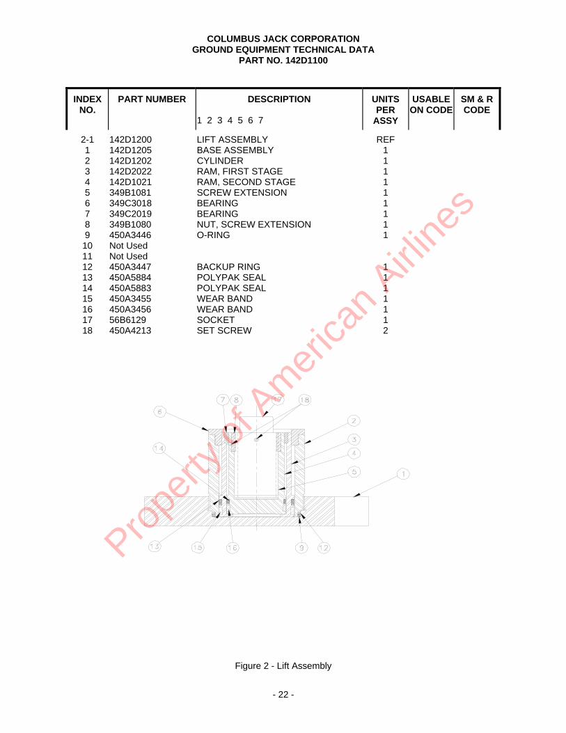
2-1 1 2 3 4 5 6 7 8 9 10 11 12 13 14 15 16 17 18
142D1200 142D1205 142D1202 142D2022 142D1021 349B1081 349C3018 349C2019 349B1080 450A3446 Not Used Not Used 450A3447 450A5884 450A5883 450A3455 450A3456 56B6129 450A4213
LIFT ASSEMBLY BASE ASSEMBLY CYLINDER RAM, FIRST STAGE RAM, SECOND STAGE SCREW EXTENSION BEARING BEARING NUT, SCREW EXTENSION O-RING BACKUP RING POLYPAK SEAL POLYPAK SEAL WEAR BAND WEAR BAND SOCKET SET SCREW
REF
1 1 1 1 1 1 1 1 1 1 1 1 1 1 1 2
Figure 2 - Lift Assembly
Prope
rty o
f Am
erica
n Airli
nes

COLUMBUS JACK CORPORATION GROUND EQUIPMENT TECHNICAL DATA PART NO. 142D1100
- 23 -
INDEX NO.
PART NUMBER
DESCRIPTION 1 2 3 4 5 6 7
UNITS PER
ASSY
USABLE ON CODE
SM & R CODE
3-1 1 2 3 4 5 6 7 8 9 10 11 12 13 14 15 16 17 18 19 20 21 22 23 24 25 26 27
566-02 AN380-3-2 AN395-49 AN395-65 230-23 220-19 70-88 151-9-02 MS28782-9 AN6227-9 566-01-11 AN380-3-7 MS19059-2415 AN6227-11 240-14 MS19059-2415 250A24-1 AN6227-7 566-01-13 59-048-250-100 20-2-51 566-01-19 AN6227-5 240-9-01 20-2-23 20-118 AN6227-11 30-182
HIGH PRESSURE HYDRAULIC PUMPCOTTER PIN PIN PIN FULCRUM LINK PLUNGER WIPER BACK-UP RING O RING PLUG COTTER PIN STEEL BALL O RING SPRING STEEL BALL FILTER O RING PLUG SPRING PIN SET SCREW NEOPRENE PLUG O RING SPRING NEEDLE BODY VALVE O RING PUMP BASE
REF
3 1 2 1 2 1 1 1 1 1 1 1 2 1 1 1 1 1 1 1 1 1 1 1 1 1 1
Prope
rty o
f Am
erica
n Airli
nes

COLUMBUS JACK CORPORATION GROUND EQUIPMENT TECHNICAL DATA PART NO. 142D1100
- 24 -
Figure 3 - High Pressure Hydraulic Pump Assembly 566-02
Prope
rty o
f Am
erica
n Airli
nes