64 - Technical University of Valencia
16
64 Removal of the coating layer of the rebar to perform the Ecorr measurement, modification: cut and saturation
Transcript of 64 - Technical University of Valencia

64
Removal of the coating layer of the rebar to perform the Ecorr measurement, modification: cut and saturation

VitruvioInternational journal of Architecture Technology and SustainabilityVolume 1 Is 1
65
ABSTRACT
1 Departamento de Construcciones Arquitectónicas, Universitat Politècnica de València2 Instituto Interuniversitario de Investigación de Reconocimiento Molecular y Desarrollo Tecnológico (IDM), Universitat Politècnica de València
Corrosion is one of the main triggering factors affecting the service life and durability of structures. Several methods are used for corrosion studies but electrochemical techniques are the most commonly applied. Corrosion processes monitoring and control by means of non-destructive techniques, such as the implementation of embedded sensors, has been the target of many works. It is possible to obtain relevant information of structural corrosion processes in real time. This document describes a system including specific equipment and which allows obtaining relevant information about these corrosion processes. This system is formed by a sensor network. There are several types of electrodes, which are distributed throughout the structure under study and a specific equipment developed by the research group, which is used to determine pertinent parameters such as the corrosion potential (Ecorr) and the corrosion density (icorr) by applying sequences of potentiostatic pulses. The system allows to reliably determine the corrosion rate in different areas of the structure. The sensor, due to its configuration, provides information of a specific area of the structure, but on the other hand it is involved in the galvanic events that can occur along the structure by differential aeration, galvanic cells, etc. because the sensor is not isolated from the structure. This system also procures information of buried and submerged elements. Besides, it is possible to obtain information related to temperature, concrete resistance. The system includes specific potentiometric sensors to monitor chloride access and carbonatation processes
KEYWORDSsensor, corrosion, structure, steel.
Integrated Sensor Network for Monitoring Steel Corrosion in Concrete Structures
José Enrique Ramón 2, José Manuel Gandía-Romero1,2, Manuel Valcuende1, Román Bataller2
http://dx.doi.org/10.4995/vitruvio-ijats.2016.5191

66
1. INTRODUCTION
1.1. THE CORROSION PROCESS
Iron found in the nature is rarely found in pure state but as many other minerals it is easily found in its oxidized form. From the iron and steel industries it is possible to obtain it in its native state, but the natural tendency of metals is to return to their natural state, therefore, to a combined state. Corrosion is a natural phenomenon commonly defined as the deterioration of a material (usually a metal) that results from a chemical or electrochemical reaction with its environment. (Van Delinder, 1984).Corrosion of rebars in reinforced concrete structures occurs when they are exposed to an aggressive environment. In fact, the majority of premature structural failure of load-bearing elements does not occur by overloading, the main reason is the reinforcement corrosion. (Garcés, 2008).Durability depends on the double protective action that concrete makes on steel in reinforced structures. The reinforcement coating is a physical and chemical barrier. The high alkalinity of concrete (pH greater than 12.5) and the existence of an appropriate electrochemical potential favor the passivating oxide film development. The layer has an electrochemical nature that can keep it unchanged if the conditions are optimal (Fraaij, 1989; González, 2004).This electrochemical passive layer formed onto the steel has a very small thickness, between 3.10 and 10.1 µm. This is a Fe3O4 - Fe2O3 solid interfacial region whose thickness varies. When the passive layer is destroyed, the rebars potential change to more electronegative values. (Sagoe-Crentsil, 1990). (Figure 1).The two main causes that can lead to the passive coating destruction are chloride attack and alkalinity decrease (by carbonation of concrete or alkali leaching usually). Other less common factors but that can also cause corrosion of the reinforcement are differential aeration batteries, galvanic macrocouples or erratic currents. These factors can take place isolated or simultaneously, which increases the severity of the process. The kinetic process control is
related to the availability of electrolyte (humidity) and the temperature (González, 2004).Corrosion leads to the formation of expansive products that generate internal stresses in the concrete causing tensions which can induce to adhesion loss and coating detachment.The monitoring of the corrosion processes in the initiation and propagation stages is necessary to ensure the life of the structure.
Figure 1.
Fe Pourbaix diagram.
1.2. THE CORROSION COSTS
From a social point of view, corrosion has been assumed on many occasions as an inevitable damage. The lack of attention to these processes involves serious and hardly measurable economic cost. Corrosion affects the direct costs associated with replacement and reparation of damages, but also there is an impact on the indirect costs associated with loss of production, including environmental aspects.According to the World Corrosion Organization (WCO) the estimated worldwide corrosion direct costs are between 1.3 and 1.4 trillion euros per year. Besides it is possible to save a 20-25% of these costs by just applying the current control technologies of

VitruvioInternational journal of Architecture Technology and SustainabilityVolume 1 Is 1
67
this phenomenon. In 2007, The Economist and the Galvanizing Spanish Technical Association (ATEG) said that the corrosion cost associated with steel in Spain was over 25,000 million euros annually. This amount was about the 2.2 per cent of the national GDP, compared to the 0.9 in other European countries (George, 2010).The costs arising from the corrosion of reinforced concrete structures are the result of their loss of utility, the necessary repair actions, and in some cases of premature demolition and replacements. In Spain, a recent study evaluates the cost of these reparations and replacements on 1,200 million euros annually (Martinez, 1998). This cost has a huge impact on the particularly affected economy. Moreover, the deterioration of these structures can only be detected when the damage is already excessively advanced, so these interventions are very expensive (Slater, 1979).These costs require investments on technological resources for the monitoring and control of structures to ensure its lifetime.
1.3. TECHNIQUES FOR THE CORROSION MEASUREMENT
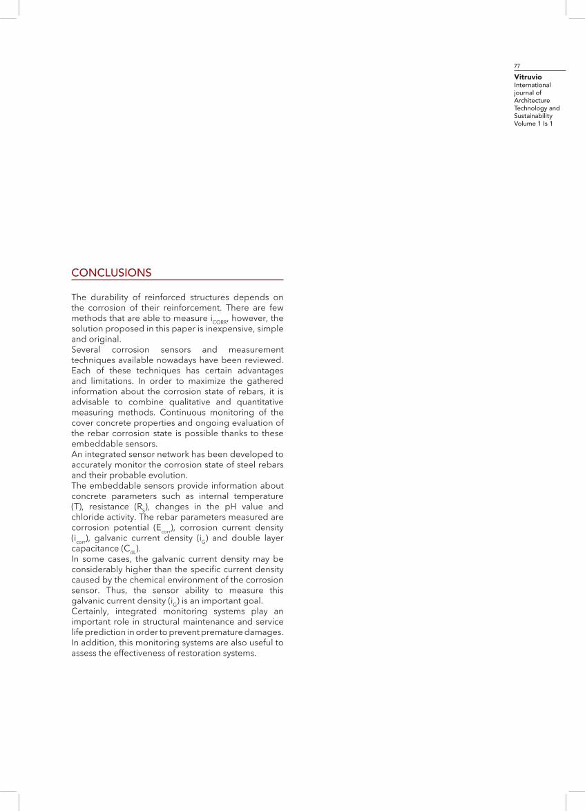
Nowadays, different techniques are used in order to evaluate the corrosion of reinforced concrete structures. On the areas to be tested it is necessary to connect the rebar, so although they are classified as non-destructive, the removal of the coating layer of the rebar is required as is shown in Figure 2. On residential, administrative, teaching, etc. buildings it is difficult to coordinate these works generating interferences with their regular activity.
1.3.1 QUALITATIVE METHODS
The Ecorr measurement is the most widely used method because it is a simple proceeding which does not require complex instrumentation. Measurements are performed against an external reference electrode, usually Cu/CuSO4, calomel-saturated Hg/Hg2Cl2 or Ag/AgCl in order to obtain the rebar reduction potential. The measurement is done as shown in Figure 3.
Figure 2.
Removal of the coating layer of the rebar to perform the Ecorr measurement.
Figure 3.
Half-Cell Potential Test Diagram.
The corrosion risk is obtained comparing the measured values with the tabulated ones from the standard: (ASTM C-876, UNE 112083).Ecorr measure ments have a simple configuration. A voltmeter measures the potential difference between the rebar (working electrode or WE) and the reference electrode (RE). An adaptation of the conventional

68
Figure 4.
Wheel Reference Electrode for potential measurement speed on large areas.
reference electrode for in situ measurements is the Canin+ where electrodes are integrated in mobile wheel systems, see Figure 4.Another qualitative method to estimate the corrosion process consists in measuring the resistivity of the concrete layer that covers the reinforcement. The Wenner method is used for this matter, it is also known as four-electrode method (ASTM WK37880).
Figure 5.
Schematic of a Wenner resistivity measurement method.
The measurement of resistivity, ρ (Ω∙cm), see Figure 5, provides information about concrete moisture. Low resistivity values favor corrosion kinetics but it must
be taken into account that this essay does not provide information about the actual state of the rebar, but has its interest when it is combined with Ecorr information.These techniques are useful to generate structure mappings and detect areas with high corrosion risk. These measurements are qualitative and therefore do not allow quantifying the corrosion level so in order to obtain information about the instantaneous corrosion rate icorr (µA/cm
2), it is necessary to use other techniques.
1.3.2 QUANTITATIVE TECHNIQUES
Is possible to use different electrochemical techniques to quantify the corrosion rate. These techniques are dynamic and can be potentiostatic or galvanostatic. The potentiostatic ones are the most commonly used, specifically the linear polarization resistance (LPR) and the Tafel extrapolation method. In the LPR technique a ±10-20 mV overpotential is applied in order to ensure that it does not affect irreversibly the rebar surface. The polarization resistance RP (Ω) is obtained from the slope of the line defined by the regression of the current I (A) versus the potential E (V). The icorr is determined by the Stern-Geary equation (Stern, 1959):
icorr = B/Rp
where the B parameter is in the range between 13 to 52 mV (González, 1989). An average value of 26 mV is usually used being 2 the maximum factor of error in the prediction (González, 1985).In the Tafel method, icorr is determined by linear extrapolation of the semi-logarithmic polarization curves (Badea, 2010). On the selection of these linear extrapolations the corrosion density (icorr) could change with a factor of error from 5 to 10 (Kelly, 2003). The linear region appears at least in the range from 50 to 100 mV of Ecorr, so they are applied overpotentials between ±100 and 200 mV in order to obtain the polarization curves. This could affect irreversibly the working electrode, therefore it can affect the surface of the rebar (Chang, 2008).

VitruvioInternational journal of Architecture Technology and SustainabilityVolume 1 Is 1
69
For "in situ" measurenents, the galvanostatic pulse is the most used method because it allows obtaining icorr through the VvsT analysis (Figure 6). When a small current pulse (µA) is applied to the system there is an initial ohmic drop (Rs) which can be related with the media and a potential change related with the rebar polarization potential (I∙Rp). Rp is calculated by experimental data fitting.
Figure 6.
V vs T analysis of a galvanostatic pulse response.
For on-site measurements there are commercial devices such as GalvaPulse, CorroEye or Gecor 8 that are able to estimate the corrosion density through the Rp value obtained by means of a galvanostatic pulse.These devices are based on a 3 electrode condiguration: the rebar as working electrode (WE), a reference electrode (RE) and a counter electrode (CE). All three of them are surrounded by a guard ring which confines the applied signal to a specific area and so the corrosion density Icorr (A) can be normalized to a known surface, (Figure 7). For in situ measurements, the Randles model used for the calculation of the Rp does not exhibit potential attenuation with the distance (Elsener, 1997).On the other hand, the guard ring should perform a modulated confinement with sensors controlling this modulation in order to avoid an icorr overestimation. In addition, confining the current within the guard ring is complicated when the concrete is too wet. (Andrade, 2001).
These portables devices are useful to evaluate the corrosion on existing structures prior to study and plan the number of monitored points and their location. Complementary laboratory studies allow getting additional information, which is nowadays fundamental to assess the specific problems of the structure under study.There are additional electrochemical techniques for the study of corrosion, such as the impedance spectroscopy, harmonic analysis, or electrochemical noise measurements. However, their implementation for on-site measurements is scarce.
Figure 7.
Gcor-8 and Galvapulse configuration for on-site measurements.

70
1.4 EMBEDDED SENSORS FOR CORROSION N MEASUREMENTS
1.4.1 EMBEDDED SENSORS
It is of great interest to introduce sensors inside reinforced concrete structures during their construction stage because they can provide real time information about the Ecorr and icorr. Analyzing the information provided by these sensors it is possible to know the state of the rebar at different locations.In the literature can be foun d some examples of embedded sensors. Those designed by Chen Xu et al., are thought to determine, at several depths, the corrosion rate by means of LPR (Chen Xu, 2013). They used small pieces of black steel as working electrodes (WE), assembled together with an auxiliary stainless steel electrode (CE) and a titanium reference electrode (RE), see Figure 8. The same configuration
follows the Concrete Multi-depth Sensor Model 900 implemented by Rohrback Cosasco Systems, which allows to detect the presence of aggressive ions through the monitoring of the galvanic currents.The company Intertek offers with their M3 and M4 models very similar corrosion sensors to those of Cosasco, but incorporating additional elements such as resistivity and temperature sensors. Figure 9 shows the multisensor developed by Duffó et. al., which is able to measure the available oxygen flow and the
Figure 8.
Corrosion sensor developed by Chen Xu et al
Figure 9.
Corrosion multisensor developed by Duffó et. al.
chloride activity (Duffo, 2009). There are examples of the application of this type of sensors placed on bridges (Martínez, 2009), hydraulic dams, waste containers (Duffó, 2012) and roofs (Castillo, 2011).The implementation of multiparametric sensors allows obtaining information not only of the corrosion rate of the structure, but also its temperature, humidity, resistivity, concentration of aggressive ions, carbonation state, etc. This information can be managed by intelligent wireless systems, without any operators visiting the structure under study. The data collected real in time from different parts of the structure provide detailed information of the state of the structure. This implies a significant improvement regarding structural safety and considerable economic savings in inspection and maintenance tasks.Other technologies such as optical fiber have also

VitruvioInternational journal of Architecture Technology and SustainabilityVolume 1 Is 1
71
been used for the development of corrosion sensors which are capable of detecting rebar section changes generated by corrosion oxides (Zhao, 2011; Gao, 2011). To achieve this, they studied the changes suffered by a light signal transmitted along these fibers which as is shown in Figure 10, are winded along steel bars of similar composition of those used as rebars.
Figure 10.
Basic structure of the Brillouin corrosion expansion sensor developed by Zhao et. al.
With the same operating philosophy was implemented a sensor which studied the oxidation of a steel sheet by focusing a light beam through an optical fiber and analyzing the reflected intensity (Leung, 2008).There are other types of sensors, made up of capacitive elements which experiment changes in the impedance of a specific system in presence of the ions liberated during the corrosion process. (Rahman, 2012)Wireless devices have also been developed. The transmission of data via a wireless method permits obtaining real time information and so program maintenance operations. A specific wireless sensor has been developed by the Fraunhofer Institute for Microelectronic Circuits and Systems (IMS).
1.4.2 SENSORS PROBLEMS
An important aspect affecting the reliability of the measurements carried out on-site at existing structures where sensors have not been embedded initially is that it is necessary to make the signal confinement accurately and to perform resistivity measurements in order to accurately determine the surface of the reinforcement under test (Song, 2007).It is also necessary to consider that on existing structures in order to gain access to the WE (rebar) it is necessary to remove the coating layer to use these techniques, as it has been described in the previous section.Embedded sensors or multi-sensors can solve the difficulties in the accurate determination of the surface of the element under test, in addition to avoid the removal of the coating for their connection.On the other hand, to obtain reliable information about the real corrosion state of the structure, if the sensor is isolated from the reinforcing structure the corrosion density will only related to the its specific chemical environment. Therefore, if the sensor remains isolated, it must be taken into consideration that it is possible that the density of the measured corrosion does not coincide with the real corrosion density of the rebar at this precise location. This occurs when galvanic macrocouples appear along the structure, i.e., when some parts of the structure act as cathode demanding electric current to the anodic zones of more electronegative potential. Some researchers have demonstrated that the corrosion density on these zones may be up to 20 times greater than those caused only by the chemical environment of the concrete (Andrade, 2008). If the embedded sensor is isolated, this is not connected to the rebar, in a certain area of the structure it does not participate directly of the global physicochemical conditions the reinforcing structure.Usually technologically complex sensors, such as optical fiber, capacitors or transponders, are based on indirect correlations with the physical event measured. These indirect correlations can also be affected by external factors such as temperature variations, or the presence of interfering agents, so

72
these sensors require of sensitive calibrations and very specific assembly procedures. Besides, their durability in some cases is limited.Another relevant issue is to get a stable long-term reference (meaning reference potential used for the measurements, usually provided by a reference electrode) in embedded systems like the just described, because it is not possible to carry out maintenance operations.
2. SENSOR NETWORK
Integrating a sensor network in a structure with a strategic location and setting the conditions to make the provided information representative of the rebar state, generally but also at specific locations, is very interesting because it makes possible to monitor different parts of the structure simultaneously. Moreover, if the system is based on an economic, simple, reliable and durable technology, it makes its implementation on new construction projects viable.The developed equipment and technology has been published on the invention patent ES2545669 and it is described in section 2.3. The system allows the accurate determination of the corrosion rate. On the other hand, the sensor network allows integrating additional sensors in order to obtain complementary information of other interesting parameters: temperature, resistivity, galvanic current, presence of chlorides and pH of the concrete.
2.1 PH SENSORS AND CHLORIDE SENSORS
The proposed sensors to monitor the chloride access and changes in pH are potentiometric thick film sensors.Potentiometry is a method based on the measurement of the potential established between two electrodes when inserted in an electrolyte (in the particular case of this study the system is concrete) without a current flow.Potentiometric sensors response in solution can be described by using the Nikolsky-Eisenman (NE)
equation. Despite being the N-E model the usual interpretation for potentiometric ion-selective sensors (ISE) and metallic electrodes, recent works reveal that metallic electrode response do not follow to the above equation when interfering ions are present (Soto, 2006; Labrador, 2007).These type of sensors have been used to control the triggering events of corrosion processes (Cl- and pH) in hardened concrete. These sensors have been characterized and the equations which predict their response have been proposed. Ag/AgCl as Cl- activity sensor, manufactured with thick film technology, with OH- as interferring ion (Gandia-Romero, 2015). The thick film has been made with resistive pastes that contain different metal oxides (Ag/Ag2O and Ru/RuO2, Ti/TiO2) to measure pH variations (Gandia-Romero, 2016); Invention Patent ES2518065). The matrix geometry used in their design allows a real time control of the chloride and carbonation penetration fronts. This type of sensors can be integrated in the network to control rebar coatings.
2.2 CORROSION SENSORS
The method used to determine the corrosion density is performed by specific hardware and software that allow applying voltammetric pulses and fit the experimental data to the theoretical model.Corrosion sensors can be used at:
New constructions, inserted at time of the concrete pouring. They are located at areas with aggressive environment (access of aggressive ions, such as chlorides, contact with aggressive soils, CO2, aeration macrocouples, high humidity...).
• Intervention works, allowing the control and non-destructive monitoring of the work effectiveness.• Laboratories, on research works to study carbonation processes in concrete specimens.
These sensors are designed to be embedded in reinforced concrete structures during their construction, therefore they can provide information

VitruvioInternational journal of Architecture Technology and SustainabilityVolume 1 Is 1
73
in real time about the corrosion potentials and the instantaneous corrosion densities at the established locations.The design takes into account that the sensor should participate of the same conditions than the rebar at the location where it was embedded. Therefore, the information obtained from these sensors is representative of the structural state at their specific location.
2.3 SENSOR DESIGN
Figure 11 shows a simplified diagram where the main elements that make up these sensors are listed (Alcañiz, 2015) Invention Patent ES2545669. They are:
• Support with the necessary strength and suitable geometry to hold the sensor on the most suitable position. In addition, it is designed to electrically connect the rebar to the sensor.• Sensing element (sensor) of known surface, suitable robustness and analogous material to the rebar to which it is to be connected.• Electrical conductors and connections between the rebar and the sensor, which allow to electrically connect the sensor to the structure or to isolate it when necessary, and making the signal available by an external connector.• Thermocouple temperature Sensor included in the sensor support.• The external connector is placed in a small connections box, which can be embedded in the concrete structure and which is accessible externally. This box is where the measurement equipment is connected, in order to obtain information about the local temperature, corrosion potential and corrosion density.
The first basic prototypes have already been implemented in concrete specimens at the laboratory, as is shown in Figures 12-13. Their geometry may change depending on where they are installed and on and the rebar diameter.
Figure 11.
Front and top schematic views of a corrosion sensor. 1. Rebar 2. Conexion clamp 3. Support 4. Sealing gasket 5. Sensor 6. Temperature sensor 7. Conexion wirings 8. External connector 9. Conexion box
▲ Figure 13.
Detail of corrosion sensor and support.
► Figure 12.
Basic prototype with assembled corrosion sensors.

74
2.2.2 CORROSION SENSOR OPERATING PRINCIPLES
The proposed sensors can operate in two possible situations:
• Natural State. When the sensor is connected to the contiguous metallic area of the structure. In this situation it takes part in the physicochemical environment conditions. The local conditions are determined by parameters such as oxygen concentration, pH, local moisture, presence of aggressive anions, temperature, etc.• Sensing State. When the sensor is disconnected from the metallic structure. The measurement is performed in a known surface of the reinforcement (coincident with the sensor’s surface). So the information obtained corresponds to the local state of the structure to which it is connected.
If a galvanic macropar exists along the rebar the sensor will also participate of it if they are electrically connected (Figure 14). Therefore, the first step is the measurement of the galvanic current (imacro) between the sensor and the structure by means of a ZRA (Zero Resistance Amperimeter).Temperature and Ecorr values are measured with the sensor in Sensing State. Then, successive squared voltage pulses are applied in order to perform the voltammetric measurement and the current versus time is recorded. This current evolution is integrated by the faradic and non-faradic responses of the current flowing throughout the system. (Figure 15).Experimental data fitting is performed using a specific software. The equivalent circuit in Figure 16 is used as theoretical model to which the experimental data are fit (Figure 17). This permits to obtain the electrical resistance (RS) of the system, the polarization resistance (RP) and the double layer capacity (CdL). The corrosion density (imicro) is obtained by a simplification of the Tafel extrapolation method. To obtain the total corrosion density (icorr), it is necessary to sum the obtained imicro and imacro values:
icorr= imicro + imacro
► Figure 14.
Corrosion sensor network operating principles schematic.
◄ Figure 15.
Current response when a potentiostatic pulse is applied. Faradic (IF), non faradic (InF) and total (ITOTAL) current curves.
To perform the test, the rebar acts as auxiliary and reference electrode, as it is a non-polarizable element since there is a high surface ratio between the embedded rebar and sensor. The guard ring usually used for the local confinement of the electric signal in a specific region is not necessary, since the corrosion sensor surface is accurately known.When working with two electrodes, the effective overpotential directly corresponds to the applied voltage pulse. An equivalent result is obtained when using the three electrodes technique but the voltage

VitruvioInternational journal of Architecture Technology and SustainabilityVolume 1 Is 1
75
values are normalized to the external reference.When working with 2 electrodes, the applied overpotencial coincides is similar to the with the designed pulse train amplitude. If it is working with When using the 3 electrodes technique is obtained an equivalent result but with the potential values normalized for the external reference.One of the advantages is that the two electrodes configuration allows monitoring structures at buried or submerged areas, where it is not possible to use external reference or auxiliary electrodes. Therefore, it is possible to measure the corrosion rate accurately, reliably and representatively. Thus, know the state of the critical areas of a structure without the need to break the concrete to reach the rebar and establish an electrical connection.
Figure 16.
Equivalent circuit used to fit the current vs. time curves.
Figure 17.
Experimental values fitting to obtain the RS, RP and CdL values.
2.2.3 CARBONATION AND CHLORIDE SENSOR
Figure 18 shows the potential evolution for three embedded sensors. The readings are plotted in a potentiometric continuous signal registered for different sensor depths. There is a potentiometric response related to chloride activity changes.
Figure 18.
Potential vs time. Response of thick film Ag/AgCl sensors embedded in a concrete specimen with a deposit-containing NaCl 0.1M solution on the top
Due to the fact that the thick film chloride sensor (TFCS) has sensors at three distances, this perpendicular distribution allows the detection of chlorides at three different depths in the specimen, providing information about the velocity of the chloride entry.For the carbonation sensor, the possibility of incorporating several electrodes in the same support allows to determine the pH value at different depths simultaneously, and therefore, to know the progression speed of the carbonation front in the concrete specimen. (see Figures 19-20, accelerated carbonation test in a climatic chamber at 26 ºC and 30% CO2 content).

76
2.3 IMPLEMENTATION AND RESULTS
The first prototypes of these corrosion sensors have been studied in laboratory by using scaled models. Fi-gure 21 shows the correlation between the corrosion density, obtained by the described pulse method, and the values obtained by the Tafel extrapolation method for different corrosion states.Figure 22 shows the corrosion density monitoring of a small network of four embedded sensors. It can be seen that the sensors connected to the structure exhi-bit higher corrosion rates compared to those which remain disconnected.
Figure 19.
pH and potential time evolution of five sensors in a concrete test specimen subjected to accelerated carbonation conditions.
Figure 20.
Phenolphthalein test in concrete specimen.
Figure 21.
Correlation between the corrosion density obtained by the pulse method and by the Tafel extrapolation method for different levels of corrosion.
Figure 22.
Corrosion density evolution for connected and non-connected sensors.
VitruvioInternational journal of Architecture Technology and SustainabilityVolume 1 Is 1
77
CONCLUSIONS
The durability of reinforced structures depends on the corrosion of their reinforcement. There are few methods that are able to measure iCORR, however, the solution proposed in this paper is inexpensive, simple and original.Several corrosion sensors and measurement techniques available nowadays have been reviewed. Each of these techniques has certain advantages and limitations. In order to maximize the gathered information about the corrosion state of rebars, it is advisable to combine qualitative and quantitative measuring methods. Continuous monitoring of the cover concrete properties and ongoing evaluation of the rebar corrosion state is possible thanks to these embeddable sensors.An integrated sensor network has been developed to accurately monitor the corrosion state of steel rebars and their probable evolution.The embeddable sensors provide information about concrete parameters such as internal temperature (T), resistance (RS), changes in the pH value and chloride activity. The rebar parameters measured are corrosion potential (Ecorr), corrosion current density (icorr), galvanic current density (iG) and double layer capacitance (CdL).In some cases, the galvanic current density may be considerably higher than the specific current density caused by the chemical environment of the corrosion sensor. Thus, the sensor ability to measure this galvanic current density (iG) is an important goal.Certainly, integrated monitoring systems play an important role in structural maintenance and service life prediction in order to prevent premature damages. In addition, this monitoring systems are also useful to assess the effectiveness of restoration systems.

78
Elsener B., Klinhoffer O., Frolund T., Rislund E., Schiegg Y., Bohni H., Assessment of reinforcement corrosion by means of galvanostatic pulse technique, International Conference on Repair of Concrete Structures. From theory to practice in a Marine Envionment. Svolvaer. Norway 20-30 may 1997. Edited by A. Blankvoll, Norwegian Public Road Administration, pp. 391 -400.
Fraaij A., Bijen J.M., de Haan Y.M., The reaction fly ash in concrete. A critical examination, Cement and concrete research 1989, 19, pp. 235-246.
Gao J., Wu J., Li J., Zhao X., Monitoring of corrosion in reinforced concrete structure using Bragg grating sensing. NDT&E Internatio-nal, 2011, vol. 44, pp. 202–205, doi: 10.1016/j.ndteint.2010.11.011.
Gandía-Romero, J.M., Román Bataller, Pablo Monzón, Inmacula-da Campos, Eduardo García-Breijo, Manuel Valcuende, Juan Soto, Characterization of embeddable potentiometric thick-film sensors for monitoring chloride penetration in concrete, Sensors and Actua-tors B: Chemical, Volume 222, January 2016, Pages 407-418. doi: 10.1016/j.snb.2015.07.056.
Gandía-Romero, J.M., Campos, I. Valcuende, M. García-Breijo, E., Marcos, M.D., Payá, J. Soto, J., Potentiometric Thick-film sensors for measuring the pH of concrete, Cement and Concrete Compo-sites, Available online 16 February 2016.doi /10.1016/j.cemcon-comp.2016.02.006.
Garcés P., Climent L., Zornoza E., Corrosión de Armaduras en Estructuras de Hormigón Armado. Ed. Club Universitario. Alicante 2008, pp. 10-13.
Gonzalez J.A., Control de la corrosión. Estudio y medida por técnic-as electroquímicas. Ed. CSIC, 1989, pp. 101-134.
González J.A., Miranda J.M., Consideraciones sobre los posibles mecanismos de corrosión de las estructuras de hormigón armado y sobre los factores que controlan su cinética. Revista de Metalurgia, 2004, 40, pp. 89-100.
Gonzalez J.A., Molina A., Escudero M.L., Andrade C., Errors in the electrochemical evaluation of very small corrosion rates–I: polari-sation resistance method applied to corrosion of steel in concrete, Corros. Sci. 1985, 25, pp. 917–930.
Leung C.K.Y., Wan K.T., Chen L., A Novel Optical Fiber Sensor for Ste-el Corrosion in Concrete Structures, Sensors 2008, vol. 8, pp. 1960-1976.
Martínez I., Andrade C., Examples of reinforcement corrosion mo-nitoring by embedded sensors in concrete structures, Cement & Concrete Composites, 2009, vol. 31, pp. 545–554, doi: 10.1016/j.cemconcomp.2009.05.007.
Martínez R., Inhibidores de corrosión para hormigón armado, Hormi-gón preparado, 1998, vol. 38, pp. 48-50.
ACKNOWLEDGMENTS
The pre-doctoral scholarship was granted to Román Bataller Prats by the Research Staff Training Program, “Formación de Personal Inve-stigador (FPI) 2012” from Universitat Politécnica de Valéncia and to José Enrique Ramón Zamora by the University Faculty Training Pro-gram FPU13/0091, “Formación del Profesorado Universitario (FPU) 2013” from the Spanish Ministry of Science and Innovation. ETSIE (UPV) by their support to the laboratory is also gratefully acknow-ledged.
REFERENCES
Andrade C., Garcés P., Martínez I., Galvanic currents and corro-sion rates of reinforcements measured in cells simulating different pitting areas caused by chloride attack in sodium hydroxide, Cor-rosion Science, 2008, vol. 50, pp. 2959–2964, doi: 10.1016/j.cor-sci.2008.07.013.
Andrade C., Martinez I., Alonso C., Fullea J., New Avanced Electro-chemical Techniques for On Site Measurements of Reinforcement Corrosion. Materiales de Construcción, 2001, vol. 51, pp. 263-264.
Badea G.E., Caraban A., Sebesan M., Dzitac S., Cret P., Setel A., Po-larisation Measurements Used for Corrosion Rates Determination, Journal of Sustenable Energy, 2010, vol. 1, nº1.
Castillo A., Andrade C., Martínez I., Rebolledo N., Fernández-Troyano L., Ayuso G., Cuervo J., Junquera J., Santana C., Delgado J., Evalua-ción y monitorización de la durabilidad de las cubiertas del Hipód-romo de la Zarzuela de Madrid. Informes de la Construcción, 2011, vol. 63, nº 524, pp. 33-41, doi: 10.3989/ic10.058.Chang Zhen-Tian, Cherry Brian, Marosszeky Marton, Polarisation behaviour of steel bar samples in concrete in seawater. Part 1: Experimental measurement of polarisation curves of steel in con-crete, Corrosion Science 2008, 50, pp. 357-364, doi: 10.1016/j.cor-sci.2007.08.009.
Chen Xu, Zhiyuan Li, Weiliang Jin, A New Corrosion Sensor to De-termine the Start and Development of Embedded Rebar Corrosion Process at Coastal Concrete, Sensors, 2013, 13, pp. 13258-13275, doi: 10.3390/s131013258.
Duffó G., Farina S.B., Development of an embeddable sensor to monitor the corrosion process of new and existing reinforced con-crete structures, Construction and Building Materials, 23, 2009, pp. 2746–2751, doi: 10.1016/j.conbuildmat.2009.04.001.
Duffó G., Arva E.A., Schulz F.M., Vazquez D.R., Evaluation of the corrosion of a reinforced concrete designed for the construction of an intermediate-level radioactive waste disposal facility, Pro-cedia Materials Science, 2012, 1, pp. 215–221, doi: 10.1016/j.mspro.2012.06.029.

VitruvioInternational journal of Architecture Technology and SustainabilityVolume 1 Is 1
79
Rahman S.F.A., Ismail M., Noor N.MD., Bakhtiar H., Embedded Capa-citor Sensor for Monitoring Corrosion of Reinforcement in Concrete, Journal of Engineering Science and Technology, 2012, vol. 7, nº 2, pp. 209–218.
Sagoe-Crentsil K. K., Glasser F. P., Analysis of the steel: concrete in-terface, in: corrosion of reinforcement in concrete, Elsevier Science Publishers Ltd. London, 1990, pp. 74-86.
Slater J., Corrosion of reinforcing steel in concrete: magnitude of the problem. Materials Performance. Jun. 1979, pp. 34-37.
Song Ha-Won, Saraswathy V., Corrosion Monitoring of Reinforced Concrete Structures – A Review, Int. J. Electrochem. Sci., 2007, vol. 2, pp. 1- 28.
Stern M., Weisert E. D., Experimental observations on the relation between polarization resistance and corrosion rate, Proc. Am. Soc. Test. Mater., 1959, 59, pp. 1280.
Van Delinder, L.S. A. Corrosion Basics, An Introduction, NACE 1984.
Zhao X., Gong P., Qiao G., Lu J., Lv X., OU J., Brillouin Corrosion Expansion Sensors for Steel Reinforced Concrete Structures Using a Fiber Optic Coil Winding Method. Sensors, 2011, vol. 11, pp. 10798-10819; doi:10.3390/s111110798.
REFERENCE NORMATIVE
ASTM C-876, Standard Test Method for Half-Cell Potential for Unco-ated Reinforcing Steel in Concrete. American Society of Testing and Materials, Philadelphia, 1987.
UNE 112083 Medición del Potencial Libre en estructuras de H.A, año 2010.
ASTM WK37880, New Test Method for Measuring the Surface Re-sistivity of Hardened Concrete Using the Wenner Four-electrode Method. American Society of Testing and Materials, 2014.
PATENTS
Alcañiz M., Bataller R., Gandía-Romero, J.M., Ramón J.E., Soto J., Valcuende M., - Universidad Politécnica de Valencia, “Sensor, red de sensores, método y programa informático para determinar la cor-rosión en una estructura de hormigón armado”, nº ES2545669 (Pa-tente de Invención concedida con Examen Previo), mayo 06, 2015.
Gandía-Romero, J.M., García-Breijo, E., Soto J., Valcuende M., - Uni-versidad Politécnica de Valencia, “Sensor para la determinación de la profundidad y velocidad de carbonatación del hormigón”, nº ES2518065 (Patente de Invención concedida con Examen Previo), febrero 11, 2015.
ONLINE SOURCES
The World Corrosion Organization. ‘Now is the Time’. George F. Hays PE., 2010, http://corrosion.org/wco_media/nowisthetime.pdf. [21/01/2016].