63-2425-01 - Q5001 Valve Linkage for Modutrol IV Motor · PRODUCT DATA 63-2425-01 Q5001 Valve...
12
PRODUCT DATA 63-2425-01 Q5001 Valve Linkage for Modutrol IV Motor APPLICATION The Q5001 Valve Linkage connects a Modutrol Motor to a 2- or 3-way valve. It is used primarily on steam and water valves such as the V5011 or V5013. FEATURES • Q5001 Valve Linkage is applicable to 2-way or 3-way valves in modulating or two position service. • Linkage requires no adjustment when used with Honeywell valves and Modutrol IV Motors (can also be used with Modutrol III motors). • Q5001 Valve Linkage replaces Q601 and Q618 Valve Linkages. • Linkage mounts directly to the valve bonnet; motor mounts on linkage bracket. • Easy-to-read position indicator. • Valve stem lift height cam selectable. • Overtravel permits tight closeoff without excessive motor strain. • Easy mounting and valve connection. • Available brackets make linkages adaptable to many valve bodies. • 80 lb, 160 lb, and 320 lb stem force models available. Contents Application ........................................................................ 1 Specifications ................................................................... 2 Ordering Information ........................................................ 2 Installation ........................................................................ 4 Operation and Checkout .................................................. 8 Replacement .................................................................... 9
Transcript of 63-2425-01 - Q5001 Valve Linkage for Modutrol IV Motor · PRODUCT DATA 63-2425-01 Q5001 Valve...

PRODUCT DATA
63-2425-01
Q5001 Valve Linkagefor Modutrol IV Motor
APPLICATION
The Q5001 Valve Linkage connects a Modutrol Motor to a 2- or 3-way valve. It is used primarily on steam and water valves such as the V5011 or V5013.
FEATURES
• Q5001 Valve Linkage is applicable to 2-way or 3-way valves in modulating or two position service.
• Linkage requires no adjustment when used with Honeywell valves and Modutrol IV Motors (can also be used with Modutrol III motors).
• Q5001 Valve Linkage replaces Q601 and Q618 Valve Linkages.
• Linkage mounts directly to the valve bonnet; motor mounts on linkage bracket.
• Easy-to-read position indicator.
• Valve stem lift height cam selectable.
• Overtravel permits tight closeoff without excessive motor strain.
• Easy mounting and valve connection.
• Available brackets make linkages adaptable to many valve bodies.
• 80 lb, 160 lb, and 320 lb stem force models available.
ContentsApplication ........................................................................ 1Specifications ................................................................... 2Ordering Information ........................................................ 2Installation ........................................................................ 4Operation and Checkout .................................................. 8Replacement .................................................................... 9

Q5001 VALVE LINKAGE FOR MODUTROL IV MOTOR
63-2425—01 2
ORDERING INFORMATION
When purchasing replacement and modernization products from your TRADELINE® wholesaler or distributor, refer to the TRADELINE® Catalog or price sheets for complete ordering number.
If you have additional questions, need further information, or would like to comment on our products or services, please write or phone:
1. Your local Honeywell Automation and Control Products Sales Office (check white pages of your phone directory).2. Honeywell Customer Care
1885 Douglas Drive NorthMinneapolis, Minnesota 55422-4386
In Canada—Honeywell Limited/Honeywell Limitée, 35 Dynamic Drive, Toronto, Ontario M1V 4Z9.International Sales and Service Offices in all principal cities of the world. Manufacturing in Australia, Canada, Finland, France, Germany, Japan, Mexico, Netherlands, Spain, Taiwan, United Kingdom, U.S.A.
SPECIFICATIONS
IMPORTANT: The specifications given in this publication do not include normal manufacturing tolerances.Therefore, an individual unit may not exactly match the listed specifications. Also, this product is tested and cali-brated under closely controlled conditions and some minor differences in performance can be expected if those conditions are changed.
TRADELINE MODELSTRADELINE MODELS are selected and packaged to provide
ease of stocking, ease of handling and maximum replace-ment value. TRADELINE model specifications are the same as those of standard models unless specified other-wise.
Table 3 on page 4
TRADELINE MODELS AVAILABLE:Q5001D1000 Valve Linkage: 3/4 in. lift, 80/160 lb force.Q5001D1018 Valve Linkage: 3/4 in. lift, 160/320 lb force.Q5001D1026 Valve Linkage: 1-1/2 in. lift, 160/320 lb force.
TRADELINE FEATURES:• Selectable close-off force to meet application
requirements.Table 1 on page 3• Special pack with Tradeline Cross Reference on label.
STANDARD MODELSQ5001A,B Valve Linkage for Modutrol IV Motors.
See Table 1 on page 3 for model specifications. (Can also be used with Modutrol III motors.)
LIFT: Selectable based on cam selection. See Table 3 on page 4 for part numbers of alternate cams.
• Q5001A is shipped with 3/4 in. lift cam, part number 220861A.
• Q5001B is shipped with 1-1/2 in. lift cam, part number 220867A.
CLOSE-OFF FORCE:See Table 2 on page 4 for motor/valve/linkage selection.
VALVE BONNET SIZE:See Table 2 on page 4 for bonnet size.
TEMPERATURE RATINGS:-40° to 150° F [-40° to 66° C] ambient air temperature.-40° to 337° F [-40° to 169° C] valve bonnet temperature.
MOTOR REQUIRED:See Table 3 on page 4.
MOTOR STROKE:160 degree rotation, mechanically normally open or nor-
mally closed.
VALVE ACTION: Determined by motor rotation, cam orientation and valve
type. Cam mounting option (up or down) allows proper control action with normally open or normally closed motors and valves.
DIMENSIONS: See Fig. 1.
WEIGHT: 6.2 pounds.
ACCESSORIES:4074ETB: Anti-spin clip, valve button and set screws for
1/4 in. [6 mm] valve stem.Cams: See Table 3 on page 4 for merchandise cam part numbers.

Q5001 VALVE LINKAGE FOR MODUTROL IV MOTOR
3 63-2425—01
Fig. 1. Approximate Q5001 Valve Linkage dimensions in in. [mm].
NOTE: High torque spring return motor shown. Medium torque spring return and nonspring return motors require less clearance on auxiliary end of motor. Linkage for 3/4 in. stroke and 1-3/8 in. valve bonnet shown. Linkage for large valve bonnet and larger stroke maximum 12 in. of clearance is required.
a If valve stroke is not 3/4 in. [19 mm], a merchandise cam must be purchased.b If valve stroke is not 1-1/2 in. [38 mm], a merchandise cam must be purchased.
Table 1. Standard Models.
Model
Valve Stem Force Lift Adjust-
mentBonnet
Connect
Bonnet Size
(O.D.) Stem ConnectAnti-Spin Linkage Replaced(lb) N
Q5001A1006 80 355.9 3/4 fixed Setscrew 1-3/8 Button and clip No Q618A1016,Q618A1032,Q618A1040,Q618A1014, Q601L, Ma
Q5001A1014 160 711.7 3/4 fixed Setscrew 1-3/8 Button and clip No Q618A1008,Q618A1024, Q601J, Ka
Q5001A1022 320 1355 3/4 fixed Setscrew 1-3/8 Button and clip No Q601Qa
Q5001B1004 160 711.7 1-1/2 fixed Setscrew 1-7/8 Button and clip Yes Q601Eb
Q5001B1012 320 1355 1-1/2 fixed Setscrew 1-7/8 Button and clip Yes Q601Pb
Q5001D1000Tradeline
80, 160
355.9-711.7
3/4 fixed Setscrew 1-3/8 Button and clip Yes Q601J, K, L, Ma
Q618A
Q5001D1018Tradeline
160, 320
711.7-1355
3/4 fixed Setscrew 1-3/8 Button and clip Yes Q601J, K, QQ618A1008a,Q618A1024
Q5001D1026Tradeline
160, 320
711.7-1355
1-1/2 fixed Setscrew 1-7/8 Button and clip Yes Q601E, Pb
OPEN
CLOSED
MOTOR NOT INCLUDEDIN LINKAGE
10
[260]
14
2764
1 [36]
1316
5 [148]
2932
6 [176]
2532
8 [223]
-10
-[267]
12
(POWER END OF MOTOR)
1/4 X 20 X 1MOUNTINGBOLTS
M3443A

Q5001 VALVE LINKAGE FOR MODUTROL IV MOTOR
63-2425—01 4
a Merchandise cam required.
a Refer to Modutrol Motor specifications to select motor with equal or greater torque. Modutrol IV Motors are available with 25 and 60 lb-in. outputs (spring return); 35, 75, 150 and 300 lb-in. (nonspring return).
b The 320 lb stem force linkage must be used with a 300 lb-in. motor.
INSTALLATION
WHEN INSTALLING THIS PRODUCT…
1. Read these instructions carefully. Failure to follow them could damage the product or cause a hazardous condi-tion.
2. Check the ratings and description given on the product to make sure the product is suitable for your application.
3. Installer must be a trained, experienced service techni-cian.
4. After installation is complete, check out product opera-tion as provided in these instructions.
5. Refer to the instruction sheet packed with the valve body for information on installing the valve.
6. Refer to the instruction sheet packed with the Modutrol IV Motor for wiring diagrams and additional installation information for the motor.
LocationSelect a location that allows ample clearance for adjustment and maintenance. Allow at least 4 in. [102 mm] above the linkage to remove the valve assembly for maintenance.
Linkages may be mounted in a variety of positions. The 320 lb stem force linkage must be assembled to a 300 lb-in. Modutrol IV Motor. The linkage and motor may be rotated 360 degrees around the valve stem. However, in all installations, the motor shaft must be horizontal to ensure proper gear train lubrication and the valve stem must be above horizontal.
Table 2. Valve-Linkage Selection Guide.
Honeywell Valve Type
ValveBody Style
PipeSize (in.) Linkage
BonnetSize (O.D.)
Lift(in.)
V5011A 2-way Flanged 2-1/2, 3 Q5001A, D 1-3/8 3/4
V5011A, B 2-way Flanged 4, 5, 6 Q5001B, D 1-7/8 1-1/2
V5011F 2-way Screwed 1/2, 3/4, 1, 1-1/4, 1-1/2, 2, 2-1/2, 3
Q5001A, D 1-3/8 3/4
V5011G 2-way Screwed 1/2, 3/4, 1, 1-1/4,1-1/2, 2, 3
Q5001A, D 1-3/8 3/4
V5013B 3-way mixing Flanged 2-1/2, 3 Q5001A, D 1-3/8 3/4
V5013B 3-way mixing Flanged 4, 5, 6 Q5001B, D 1-7/8 1-1/2
V5013C 3-way diverting Flanged 2-1/2, 3 Q5001A, D 1-3/8 3/4
V5013C 3-way diverting Flanged 4, 5, 6 Q5001B, D 1-7/8 1-1/2
V5047A 2-way Screwed 1, 1-1/4, 1-1/2 Q5001A, D 1-3/8 9/16a
V5047A 2-way Screwed 2 Q5001A, D 1-3/8 3/4
V5051A 2-way Flanged 2-1/2, 3, 4, 5, 6 Q5001B, D 1-3/8 1-1/2
Table 3. Cam Selections Available.
Cam Number Type Lift
Required Torquea (lb-in.)
Application80 lb stem
force
160 lb stem force
320 lb stem
forceb
220858A Custom 9/16 in. 25 50 100 V5047A, 1 in. to 1-1/2 in.
220861A Standard 3/4 in. 25 50 100 V5011/V5013, 1/2 in. to 3 in.;V5047A, 2 in.
220863A Custom 1 in. 30 60 120
220864A Custom 1-1/8 in. 30 60 120
220865A Custom 1-1/4 in. 50 100 200
220867A Standard 1-1/2 in. 50 100 200 V5011/V5013, 4 in. to 6 in.
Q5001 VALVE LINKAGE FOR MODUTROL IV MOTOR
5 63-2425—01
CAUTIONWhen mounting the linkage to the valve, make sure that the set screws holding the valve linkage to the valve body are properly tightened to prevent improper operation or damage to the equipment. The torque for tightening these screws should be in the range of 72 to 120 lb-in.
Mounting
ToolsTools required for installing the linkage are:• 5/32 in. hex wrench.• 7/16 in. open end or box end wrench.
Mount Linkage to Valve1. Loosen the two valve bracket set screws, if necessary,
and slide the linkage over the valve stem and bonnet until the valve bracket rests on the shoulder of the valve bonnet.
2. Tighten the two valve bracket set screws to secure the linkage to the valve. Make sure that the set screws hold-ing the valve linkage to the valve body are properly tight-ened to prevent damage to the equipment. The torque for tightening these screws should be in the range of 72 to 120 lb-in.
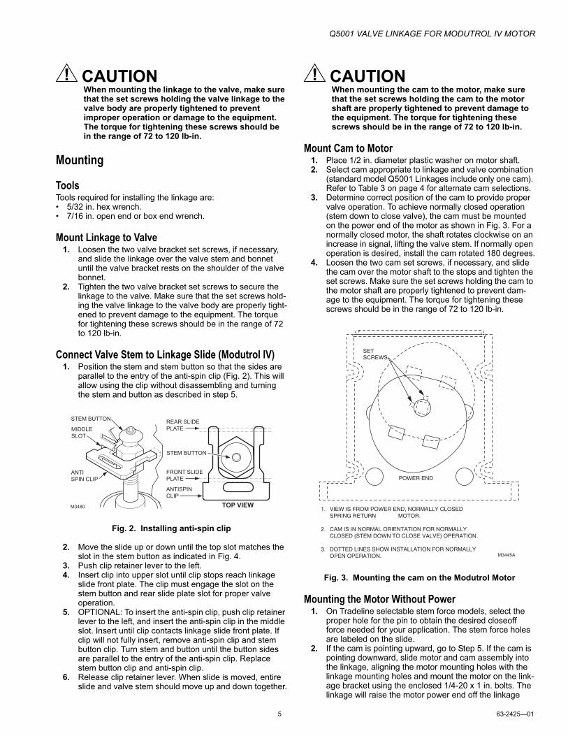
Connect Valve Stem to Linkage Slide (Modutrol IV)1. Position the stem and stem button so that the sides are
parallel to the entry of the anti-spin clip (Fig. 2). This will allow using the clip without disassembling and turning the stem and button as described in step 5.
Fig. 2. Installing anti-spin clip
2. Move the slide up or down until the top slot matches the slot in the stem button as indicated in Fig. 4.
3. Push clip retainer lever to the left.4. Insert clip into upper slot until clip stops reach linkage
slide front plate. The clip must engage the slot on the stem button and rear slide plate slot for proper valve operation.
5. OPTIONAL: To insert the anti-spin clip, push clip retainer lever to the left, and insert the anti-spin clip in the middle slot. Insert until clip contacts linkage slide front plate. If clip will not fully insert, remove anti-spin clip and stem button clip. Turn stem and button until the button sides are parallel to the entry of the anti-spin clip. Replace stem button clip and anti-spin clip.
6. Release clip retainer lever. When slide is moved, entire slide and valve stem should move up and down together.
CAUTIONWhen mounting the cam to the motor, make sure that the set screws holding the cam to the motor shaft are properly tightened to prevent damage to the equipment. The torque for tightening these screws should be in the range of 72 to 120 lb-in.
Mount Cam to Motor1. Place 1/2 in. diameter plastic washer on motor shaft.2. Select cam appropriate to linkage and valve combination
(standard model Q5001 Linkages include only one cam). Refer to Table 3 on page 4 for alternate cam selections.
3. Determine correct position of the cam to provide proper valve operation. To achieve normally closed operation (stem down to close valve), the cam must be mounted on the power end of the motor as shown in Fig. 3. For a normally closed motor, the shaft rotates clockwise on an increase in signal, lifting the valve stem. If normally open operation is desired, install the cam rotated 180 degrees.
4. Loosen the two cam set screws, if necessary, and slide the cam over the motor shaft to the stops and tighten the set screws. Make sure the set screws holding the cam to the motor shaft are properly tightened to prevent dam-age to the equipment. The torque for tightening these screws should be in the range of 72 to 120 lb-in.
Fig. 3. Mounting the cam on the Modutrol Motor
Mounting the Motor Without Power1. On Tradeline selectable stem force models, select the
proper hole for the pin to obtain the desired closeoff force needed for your application. The stem force holes are labeled on the slide.
2. If the cam is pointing upward, go to Step 5. If the cam is pointing downward, slide motor and cam assembly into the linkage, aligning the motor mounting holes with the linkage mounting holes and mount the motor on the link-age bracket using the enclosed 1/4-20 x 1 in. bolts. The linkage will raise the motor power end off the linkage
STEM BUTTON
MIDDLESLOT
ANTI SPIN CLIP
M3480
REAR SLIDE PLATE
FRONT SLIDEPLATE
STEM BUTTON
ANTISPIN CLIP
TOP VIEW
POWER END
M3445A
VIEW IS FROM POWER END, NORMALLY CLOSED SPRING RETURN MOTOR.
CAM IS IN NORMAL ORIENTATION FOR NORMALLY CLOSED (STEM DOWN TO CLOSE VALVE) OPERATION.
DOTTED LINES SHOW INSTALLATION FOR NORMALLY OPEN OPERATION.
1.
2.
3.
SET SCREWS

Q5001 VALVE LINKAGE FOR MODUTROL IV MOTOR
63-2425—01 6
motor bracket. It may be necessary to squeeze the motor auxiliary end of the linkage bracket slightly to align the mounting holes.
3. Start all four motor bolts, then tighten the bolts on the power end first, pulling the motor snugly to the linkage motor bracket and compressing the linkage springs.
4. Tighten the auxiliary end mounting bolts.
5. If the cam is pointing upward, remove motor wiring cover (on nonspring return motors) and raise the linkage slide.
6. Tilt the motor power end face down about 30° and slide motor and cam assembly into linkage opening at an angle to align one power end bolt hole. Make sure that the cam is between the linkage rollers. See Fig. 5(A).
Fig. 4. Stem force pin position selection.
FRONT SLIDE PLATE
REAR SLIDE PLATE
SET SCREW
CLIP IN SLOT
STEM BUTTON
VALVE STEM
M2774
STEM FORCE PINS
PIN LOCKED POSITION
PIN REMOVAL POSITION
MODUTROL IV MOTOR CLIP SLOT
MODUTROL IV ANTI-SPINCLIP SLOT
MODUTROL III MOTORCLIP SLOTCLIP RETAINING
LEVER
CLIP MUST ENGAGE SLOTS ON STEM BUTTON AND REAR SLIDE PLATE.
CHOOSE TOP SLOT IN SLIDE FOR MODUTROL IV OR BOTTOM SLOT FOR MODUTROL III
1
2
12
SLIDE
PUSH HERE

Q5001 VALVE LINKAGE FOR MODUTROL IV MOTOR
7 63-2425—01
Fig. 5. Mounting Modutrol Motor to Q5001 Valve Linkage with cam pointing up.
7. Install bolt but do not tighten.8. Rotate motor to align the other power end bolt hole (B)
and install second bolt, but do not tighten at this time.9. Install auxiliary end mounting bolts and tighten (C), pull-
ing auxiliary end of motor snugly to linkage motor bracket. It may be necessary to squeeze the motor auxil-iary end of the linkage bracket slightly to align the mount-ing holes.
10. Tighten power end mounting bolts.
NOTE: If motor and linkage are assembled without power, the operation and checkout must be performed to guarantee proper performance.
Mounting the Motor With Power Available(Optional Means)
1. For easier assembly, run the motor to mid-stroke. Refer to Modutrol Motor Specification for instructions on oper-ating the motor.
2. OPTIONAL: Remove the upper force pin, push up the lever arm as indicated in Fig. 4 and replace pin in posi-tion to hold the lever arm away from the opening to allow the cam and motor assembly to slide into position easily. Repeat for the lower force pin. The lower force pin must be placed in the outer hole, because the valve stem but-ton limits the lever movement, preventing inner hole alignment. Refer to Fig. 4.
3. Slide motor and cam assembly into opening, align the motor mounting holes with the linkage mounting holes and assemble the motor to the motor brackets using the enclosed 1/4 - 20 x 1 in. bolts, but do not tighten. It may
be necessary to squeeze the motor auxiliary end of the Q5001 Valve Linkage slightly to align the mounting holes. See Fig. 1.
4. If levers were held out of the way in Step 2, remove the force pins and allow levers to return to operating posi-tion. Insert pins in the proper hole for the pin to obtain the desired closeoff force needed in your application and rotate to the locked position as shown in Fig. 4.
5. Tighten the 1/4 x 20 x 1 in. motor bolts.
NOTE: Both upper and lower stem force pins must be in the same force hole location to make sure that proper seal off force for the valve is applied. Failure to lock arms in location with stem force pins will prevent the valve from closing.
Final AssemblyAfter checkout (see “Operation and Checkout” on page 8), install the position indicator on the cam. The center of the indicator should coincide with the center of the motor shaft, see Fig. 3. This will allow the indicator to show position of the valve through the cover of the motor.
The indicator is shipped with arrow label for normally closed valve operation. On a normally open valve, install the spare indicator label at 180° to the original label.
Place the cover on the linkage by positioning the cover with the hole centered over the indicator, label oriented upwards. Press the cover over the linkage frame until the indents snap into place on the frame. Run the valve through two operating cycles to make sure that no binding occurs during operation.
A B C
M2773

Q5001 VALVE LINKAGE FOR MODUTROL IV MOTOR
63-2425—01 8
OPERATION AND CHECKOUT
The Q5001 Valve Linkage operates the valve in a 160-degree stroke. See Fig. 6. As shown, a normally closed spring return motor will rotate the cam through the 160-degree stroke to lift the stem the distance prescribed by the selected cam. On loss of power, the spring will return the motor, linkage and valve to the closed position.
For normally open spring return models, reverse the closed and open captions in Fig. 6.
After installation and adjustment are completed, run valve/linkage/motor combination through two or more full cycles to make sure the combination operates properly.
Refer to the appropriate Modutrol IV Motor instruction sheet for information on running the motor during checkout.
1. A 2-way valve should close off tightly at the closed end of its stroke.
2. A 3-way valve should close off tightly at both ends of its stroke. See Table 4 on page 8.
3. The motor should be free to run through its complete stroke without stalling.
4. The linkage should operated freely without binding.
LubricationThe Q5001 does not require any lubrication.
Spring CompressionSpring compression for the Q5001 is shown in Table 4 on page 8.
If spring compression is less than minimum or more than maximum, verify that the correct cam was used. If the correct cam was used, remove valve stem clip and adjust valve stem button after set screw has been loosened. See Table 4 on page 8.
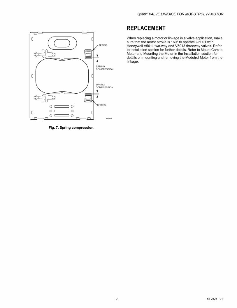
Measure spring compression by measuring the distance between the lever end and the end of the spring slot. See Fig. 7.
Fig. 6. Q5001 operation.
Maximum spring compression = 11/32 in. [8.7 mm].
Table 4. Minimum Spring Compression in in. [mm] (See Fig. 6.).
O.S. Number
Stem Force Load
80 lb 160 lb 320 lb
Q5001A1006 3/64 [1.2]
Q5001A1014 3/32 [2.4]
Q5001D1000 3/64 [1.2] 3/32 [2.4]
Q5001D1018 3/64 [1.2] 3/32 [2.4]
Q5001D1026 3/64 [1.2] 3/32 [2.4]
M5400
1
160˚
10˚
CWMOTORLIMIT
OPEN
2-WAY OR3-WAYVALVE
CLOSE
10˚
CWMOTORLIMIT
2
VALVE CENTER LINE
LINES REPRESENT POSITION OF CAMS (VIEWED FROM POWER END OF MOTOR).
SPRING RETURN MODELS: SPRING DRIVES MOTOR AND VALVE CLOSED IF POWER IS TURNED OFF.
2
1
Q5001 VALVE LINKAGE FOR MODUTROL IV MOTOR
9 63-2425—01
Fig. 7. Spring compression.
REPLACEMENT
When replacing a motor or linkage in a valve application, make sure that the motor stroke is 160° to operate Q5001 with Honeywell V5011 two-way and V5013 threeway valves. Refer to Installation section for further details. Refer to Mount Cam to Motor and Mounting the Motor in the Installation section for details on mounting and removing the Modutrol Motor from the linkage.
SPRING COMPRESSION
SPRING
SPRING COMPRESSION
SPRING
M3444

Q5001 VALVE LINKAGE FOR MODUTROL IV MOTOR
63-2425—01 10

Q5001 VALVE LINKAGE FOR MODUTROL IV MOTOR
11 63-2425—01

Automation and Control Solutions
Honeywell International Inc. Honeywell Limited-Honeywell Limitée
1985 Douglas Drive North 35 Dynamic Drive
Golden Valley, MN 55422 Toronto, Ontario M1V 4Z9
customer.honeywell.com
Q5001 VALVE LINKAGE FOR MODUTROL IV MOTOR
® U.S. Registered Trademark© 2008 Honeywell International Inc.63-2425—01 M.S. Rev. 12-08
By using this Honeywell literature, you agree that Honeywell will have no liability for any damages arising out of your use or modification to, the literature. You will defend and indemnify Honeywell, its affiliates and subsidiaries, from and against any liability, cost, or damages, including attorneys’ fees, arising out of, or resulting from, any modification to the literature by you.