60D Excavator - Moffat Pipemoffatpipe.com/Equipment-Manuals/EXC 05 - JD60D/EXC 05 - 60D... · 60D...
178
60D Excavator *OMT244925* OPERATOR'S MANUAL 60D Excavator OMT244925 ISSUE A3 (ENGLISH) CALIFORNIA Proposition 65 Warning Diesel engine exhaust and some of its constituents are known to the State of California to cause cancer, birth defects, and other reproductive harm. If this product contains a gasoline engine: WARNING The engine exhaust from this product contains chemicals known to the State of California to cause cancer, birth defects or other reproductive harm. The State of California requires the above two warnings. Additional Proposition 65 Warnings can be found in this manual. Worldwide Construction And Forestry Division LITHO IN U.S.A.
Transcript of 60D Excavator - Moffat Pipemoffatpipe.com/Equipment-Manuals/EXC 05 - JD60D/EXC 05 - 60D... · 60D...
60DExcavator
*OMT244925*
OPERATOR'S MANUAL60D Excavator
OMT244925 ISSUE A3 (ENGLISH)
CALIFORNIAProposition 65 Warning
Diesel engine exhaust and some of its constituentsare known to the State of California to cause cancer,
birth defects, and other reproductive harm.
If this product contains a gasoline engine:
WARNING
The engine exhaust from this product containschemicals known to the State of California to causecancer, birth defects or other reproductive harm.
The State of California requires the above two warnings.
Additional Proposition 65 Warnings can be found in this manual.
Worldwide ConstructionAnd Forestry Division
LITHO IN U.S.A.

Introduction
DX,IFC7 -19-03APR09-1/1
Foreword
READ THIS MANUAL carefully to learn how to operateand service your machine correctly. Failure to do socould result in personal injury or equipment damage.This manual and safety signs on your machine may alsobe available in other languages. (See your John Deeredealer to order.)
THIS MANUAL SHOULD BE CONSIDERED a permanentpart of your machine and should remain with the machinewhen you sell it.
MEASUREMENTS in this manual are given in bothmetric and customary U.S. unit equivalents. Use onlycorrect replacement parts and fasteners. Metric and inchfasteners may require a specific metric or inch wrench.
RIGHT-HAND AND LEFT-HAND sides are determined byfacing in the direction of forward travel.
WRITE PRODUCT IDENTIFICATION NUMBERS (P.I.N.)in the Machine Numbers section. Accurately record allthe numbers to help in tracing the machine should it bestolen. Your dealer also needs these numbers when youorder parts. File the identification numbers in a secureplace off the machine.
WARRANTY is provided as part of John Deere's supportprogram for customers who operate and maintain their
equipment as described in this manual. The warranty isexplained on the warranty certificate or statement whichyou should have received from your dealer.
This warranty provides you the assurance that JohnDeere will back its products where defects appear withinthe warranty period. In some circumstances, John Deerealso provides field improvements, often without chargeto the customer, even if the product is out of warranty.Should the equipment be abused, or modified to changeits performance beyond the original factory specifications,the warranty will become void and field improvementsmay be denied. Setting fuel delivery above specificationsor otherwise overpowering machines will result in suchaction.
THE TIRE MANUFACTURER'S warranty supplied withyour machine may not apply outside the U.S.
If you are not the original owner of this machine, it is inyour interest to contact your local John Deere dealer toinform them of this unit's serial number. This will help JohnDeere notify you of any issues or product improvements.
013013
PN=2

Introduction
OUO1065,000006C -19-08JAN08-1/1
Emission Control Statement
EMISSIONS CONTROL WARRANTY STATEMENT FOR NEW JOHN DEERE CONSTRUCTION EQUIPMENT (U.S. AND CANADA)
To determine if the engine in your machine qualifies for the additional warranties set forth below, look for the "Engine Information" label located on your engine. If you reside in the United States and the engine label states: "Engine conforms to US EPA regulations on heavy duty non road diesel cycle engines," you are entitled to the "U.S. Emission Control Warranty Statement." If you reside in California, and the engine label states: "Engine conforms to California regulations on heavy duty non road diesel cycle engines," you are entitled to the "California Emission Control Warranty Statement."
U.S. EPA EMISSIONS CONTROL WARRANTY STATEMENT
CALIFORNIA EMISSION CONTROL WARRANTY STATEMENT
Emissions control-related parts and components are warranted by John Deere for five years or 3000 hours of operation, whichever occurs first. John Deere further warrants that the engine covered by this warranty was designed, built, and equipped so as to conform at the time of sale with all U.S. emissions standards at the time of manufacture, and that it is free of defects in materials and workmanship which would cause it not to meet these standards within the period of five years or 3000 hours of operations, whichever occurs first.
Operator's Manual. John Deere recommends that you retain all receipts covering maintenance on your heavy-duty engine, but John Deere cannot deny warranty solely for the lack of receipts or for your failure to ensure the performance of all scheduled maintenance.
However, as the heavy-duty engine owner, you should be aware that John Deere may deny you warranty coverage if your heavy- duty engine or a part has failed due to abuse, neglect, improper maintenance or unapproved modifications.
Your engine is designed to operate on diesel fuel only. Use of any other fuel may result in your engine no longer operating in compliance with California's emissions requirements.
You are responsible for initiating the warranty process. The CARB suggests that you present your machine to the nearest authorized John Deere dealer as soon as a problem is suspected. The warranty repairs should be completed by the service dealer as expeditiously as possible.
If you have any questions regarding your warranty rights and responsibilities, you should contact John Deere at 1-319-292- 5400, or the State of California Air Resources Board, Mobile Source Operation Division, PO Box 8001, El Monte, CA 91731-2900
The warranty period begins on the date the machine is delivered to an ultimate purchaser, or when otherwise put into service. John Deere warrants to the ultimate purchaser and each subsequent purchaser that the engine is designed, built and equipped so as to conform with all applicable regulations adopted by the Air Resources Board, and that it is free from defects in materials and workmanship which would cause the failure of a warranted part.
Any warranted part which is scheduled for replacement as required maintenance by the operator's manual is warranted by John Deere for the period of time prior to the first scheduled replacement point for that part. If the part fails prior to the first scheduled replacement point, the part shall be repaired or replaced under warranty. Any such part repaired or replaced under warranty is warranted for the remainder of the period prior to the first scheduled replacement point for that part.
Any warranted part which is not scheduled for replacement as required maintenance, or which is scheduled only for regular inspection to the effect of repairing or replacing as necessary, is warranted for the warranty period.
Repair or replacement of a warranted part will be performed at no charge to you by an authorized John Deere dealer. You will not be charged for diagnostic labor which leads to the determination that a warranted part is defective, if the diagnostic work is performed by a John Deere dealer.
John Deere is liable for damages to other engine components caused by failure under warranty of any warranted part.
John Deere is NOT liable for travel or mileage on extended emissions warranty service calls.
Any replacement part may be used in the performance of any maintenance or repairs, and such use will not reduce the warranty obligations of John Deere. However, the use of add-on or modified parts are grounds for disallowing a warranty claim.
Warranties stated on this certificate refer only to emissions-related parts and components of your engine. The complete machine warranty, less emisions-related parts and components, is provided separately as "John Deere "Secure Warranty" For New Construction Products."
YOUR WARRANTY RIGHTS AND OBLIGATIONS
JOHN DEERE'S WARRANTY COVERAGE:
OWNER'S WARRANTY RESPONSIBILITIES:
As the heavy-duty engine owner, you are responsible for the performance of the required maintenance as outlined in the
The California Air Resources Board (CARB) and John Deere are pleased to explain the emission control system on your new engine. In California, new heavy-duty engines must be designed, built and equipped to meet the State's stringent anti-smog standards. John Deere must warrant the emission control system on your engine for the periods of time listed below provided there has been no abuse, neglect, or improper maintenance of your machine.
Where a warrantable condition exists, i.e. failure due to defect in John Deere-supplied material and/or workmanship, John Deere will repair your heavy-duty engine at no cost to you including diagnosis, parts and labor
The emission control system of your heavy-duty engine is warranted for five years or 3000 hours of operation, whichever occurs first. If any emission-related part on your engine is defective, the part will be repaired or replaced by John Deere. Warranties stated on this certificate refer only to emissions-related parts and components of your engine. The complete machine warranty, less emissions-related parts and components, is provided separately as the "John Deere "Secure Warranty" For New Construction Products."
Your emissions control system includes: Fuel Metering System Fuel Injection System Air Induction System Intake Manifold Turbocharger System Charge Air Cooling System Miscellaneous Items used in Above Systems
T132126—19—28JU
N00
013013
PN=3

Introduction
TX,TM,FAX -19-03JUL01-1/1
Technical Information Feedback FormWe need your help to continually improve our technicalpublications. Please copy this page and FAX or mail yourcomments, ideas and improvements.SEND TO: John Deere Dubuque Works
18600 South John Deere RoadAttn: Publications, Dept. 324Dubuque, IA 52004-0538USA
FAX NUMBER: 1-563-589-5800 (USA)
Publication Number:
Page Number:
Ideas, Comments:
Name:
Phone:
Email Address:
THANK YOU!
013013
PN=4

Contents
Page
Safety—Safety and Operator ConveniencesSafety and Operator Convenience Features .....1-1-1
Safety—General PrecautionsRecognize Safety Information ...........................1-2-1Follow Safety Instructions..................................1-2-1Operate Only If Qualified...................................1-2-1Wear Protective Equipment...............................1-2-2Avoid Unauthorized Machine Modifications.......1-2-2Add Cab Guarding for Special Uses..................1-2-2Inspect Machine ................................................1-2-2Stay Clear of Moving Parts................................1-2-3Avoid High-Pressure Fluids ...............................1-2-3Avoid High-Pressure Oils ..................................1-2-3Beware of Exhaust Fumes ................................1-2-4Prevent Fires .....................................................1-2-4Prevent Battery Explosions ...............................1-2-4Handle Chemical Products Safely .....................1-2-5Dispose of Waste Properly ................................1-2-5Prepare for Emergencies...................................1-2-5
Safety—Operating PrecautionsUse Steps and Handholds Correctly .................1-3-1Start Only From Operator's Seat .......................1-3-1Use and Maintain Seat Belt ...............................1-3-1Prevent Unintended Machine Movement ..........1-3-1Avoid Work Site Hazards...................................1-3-2Keep Riders Off Machine ..................................1-3-2Avoid Backover Accidents .................................1-3-3Avoid Machine Tip Over ....................................1-3-3Use Special Care When Lifting Objects ............1-3-4Add and Operate Attachments Safely ...............1-3-4
Safety—Maintenance PrecautionsPark and Prepare for Service Safely .................1-4-1Service Cooling System Safely .........................1-4-1Remove Paint Before Welding or Heating.........1-4-2Make Welding Repairs Safely ...........................1-4-2Drive Metal Pins Safely .....................................1-4-2
Safety—Safety SignsSafety Signs ......................................................1-5-1
Operation—Operator's StationPedals, Levers, and Panels...............................2-1-1Monitor Panel and Functions (S.N. —280538) ..2-1-3
Page
Monitor Panel and Functions (S.N.280539— ) ....................................................2-1-4
Switch Panel and Functions (S.N. —280538) ...2-1-5Switch Panel and Functions (S.N.
280539— ) ....................................................2-1-6Key Switch.........................................................2-1-6Horn...................................................................2-1-7Engine Speed Control Knob..............................2-1-7Pilot Control Shutoff Lever.................................2-1-8Travel Alarm and Travel Alarm Cancel
Switch (S.N. —280538).................................2-1-8Cab Heater and Air Conditioner ........................2-1-9Setting Trip Meters (S.N. —280538) ...............2-1-11Operating AM/FM Radio..................................2-1-12Secondary Exit Tool.........................................2-1-13Opening Front Upper (Secondary Exit)
Window .......................................................2-1-14Removing Lower Front Window ......................2-1-14Opening Cab Window......................................2-1-15Door Release Lever.........................................2-1-15Adjusting Operator's Seat................................2-1-15
Operation—Operating the MachineBefore Starting Work .........................................2-2-1Operator's Daily Machine Check
Before Starting ..............................................2-2-1Starting the Engine............................................2-2-2Cold Weather Warm-Up ....................................2-2-2Travel Pedals and Levers..................................2-2-3Control Lever Pattern Operation........................2-2-4Control Lever Pattern Conversion .....................2-2-5Operating Angle Blade—If Equipped.................2-2-6Operating Backfill Blade ....................................2-2-7Operating Tips—Backfill Blade..........................2-2-7Auxiliary Pedal—If Equipped (S.N. —280333) ..2-2-8Auxiliary Function Lever Switch—If
Equipped (S.N. 280334— ) ...........................2-2-9Positioning Auxiliary Line Selector Valve.........2-2-10Operating In Water and Mud ...........................2-2-10Driving Up a Steep or Slippery Slope..............2-2-11Lifting...............................................................2-2-11Lowering Boom With Engine Stopped.............2-2-12Parking Machine..............................................2-2-12Loading and Unloading for Transport ..............2-2-13Towing Machine...............................................2-2-13Lifting Machine ................................................2-2-14
Continued on next page
Original Instructions. All information, illustrations and specifications in thismanual are based on the latest information available at the time of publication.
The right is reserved to make changes at any time without notice.COPYRIGHT © 2013DEERE & COMPANY
Moline, IllinoisAll rights reserved.
A John Deere ILLUSTRUCTION ® ManualPrevious Editions
Copyright © 2008, 2009, 2011, 2012
i 013013
PN=1

Contents
Page
Maintenance—MachineDiesel Fuel.........................................................3-1-1Biodiesel Fuel ....................................................3-1-2Testing Diesel Fuel ............................................3-1-3Handling and Storing Diesel Fuel ......................3-1-3Alternative and Synthetic Lubricants .................3-1-4Diesel Engine Oil ...............................................3-1-4Diesel Engine Oil and Filter Service Intervals ...3-1-5Hydraulic Oil ......................................................3-1-6Swing Gearbox and Travel Gearbox Oils ..........3-1-6Track Adjuster, Working Tool Pivot,
Swing Bearing, and Swing BearingGear Grease .................................................3-1-7
Heavy Duty Diesel Engine Coolant ...................3-1-7Drain Intervals for Diesel Engine Coolant..........3-1-8John Deere COOL-GARD™ II Coolant
Extender........................................................3-1-8Supplemental Coolant Additives........................3-1-9Operating in Warm Temperature Climates ........3-1-9Additional Information About Diesel
Engine Coolants and John DeereCOOL-GARD™ II Coolant Extender ...........3-1-10
Testing Diesel Engine Coolant.........................3-1-11
Maintenance—Periodic MaintenanceService Machine at Specified Intervals..............3-2-1Check the Hour Meter Regularly .......................3-2-1Prepare Machine for Maintenance ....................3-2-2Opening Access Doors and Covers for
Service ..........................................................3-2-3Tilting the Operator Station................................3-2-5Fuel Tank...........................................................3-2-6Checking Washer Fluid Level............................3-2-6Hydraulic Breaker and Crusher Attachments ....3-2-7Maintenance and Repair Record
Keeping System............................................3-2-7Fluid Analysis Program Test Kits and
3-Way Coolant Test Kit..................................3-2-8Service Intervals ................................................3-2-9Required Parts.................................................3-2-10
Maintenance—As RequiredCleaning Air Cleaner Element ...........................3-3-1Cleaning Radiator Core and Oil Cooler .............3-3-1Check Coolant ...................................................3-3-2
Maintenance—Every 10 Hours or DailyChecking Engine Oil Level ................................3-4-1Checking Hydraulic Oil Tank Level ....................3-4-2Draining Fuel Tank Sump ..................................3-4-2Draining Water Separator..................................3-4-3Checking Recovery Tank Coolant Level............3-4-3Checking Bucket Teeth......................................3-4-3Checking Track Sag—Rubber Track .................3-4-4Checking Track Sag—Steel Track—If
Equipped .......................................................3-4-5Adjusting Track Sag ..........................................3-4-6
Page
Use and Maintain Seat Belt ...............................3-4-6
Maintenance—Initial Service—50 HoursLubricate Bucket and Link Pins .........................3-5-1Lubricate Front Joint Pins..................................3-5-2Check and Adjust Fan Belt Tension...................3-5-3
Maintenance—Every 100 HoursLubricate Bucket and Link Pins .........................3-6-1Lubricate Front Joint Pins..................................3-6-2Check and Adjust Fan Belt Tension...................3-6-3
Maintenance—Initial Service—250 HoursReplacing Hydraulic Oil Tank Filter....................3-7-1
Maintenance—Every 250 HoursLubricate Swing Bearing....................................3-8-1Lubricate Tilt Mechanism...................................3-8-1Lubricate Angle Blade Bottom and Rod
Pins—If Equipped .........................................3-8-2Checking Travel Gear Case Oil Level ...............3-8-2Draining Hydraulic Oil Tank Sump.....................3-8-3Take Engine Oil Sample ....................................3-8-3
Maintenance—Every 500 HoursChanging Engine Oil and Replacing Filter.........3-9-1Lubricate Front Joint Pins..................................3-9-2Lubricate Swing Bearing Gear...........................3-9-3Lubricate Control Lever Universal Joint.............3-9-3Replacing Final Fuel Filter.................................3-9-4Lubricate Blade Pins..........................................3-9-4Lubricate Center Pin—If Equipped....................3-9-4Replace Air Cleaner Elements and
Dust Valve .....................................................3-9-5Take Fluid Samples ...........................................3-9-6
Maintenance—Every 1000 HoursCheck Coolant .................................................3-10-1Changing Travel Gearbox Oil ..........................3-10-1Replacing Pilot System Oil Filter .....................3-10-2Checking and Adjusting Engine Valve
Lash (Clearance).........................................3-10-3Checking Starter and Alternator ......................3-10-3Inspecting Crankcase Breather System ..........3-10-3
Maintenance—Every 2000 HoursDraining Cooling System.................................3-11-1Heavy Duty Diesel Engine Coolant .................3-11-2Cooling System Fill and Deaeration ................3-11-2Changing Hydraulic Tank Oil ...........................3-11-3
Miscellaneous—MachineDo Not Service or Adjust Injection
Nozzles or High Pressure Fuel Pump ...........4-1-1Do Not Service Control Valves,
Cylinders, Pumps, or Motors.........................4-1-1
Continued on next page
ii 013013
PN=2

Contents
Page
Cleaning Fuel Tank Inlet Screen........................4-1-1Check Cab Fresh Air Filter ................................4-1-1Check Cab Recirculating Air Filter.....................4-1-2Check Air Intake Hoses.....................................4-1-3Clean Air Cleaner Dust Valve ............................4-1-3Replace Water Separator Element....................4-1-4Prime Fuel System ............................................4-1-4Precautions for Alternator and Regulator ..........4-1-4Checking Starter and Alternator ........................4-1-4Check Battery Electrolyte Level and Terminals ..4-1-5Handling, Checking, and Servicing
Batteries Carefully.........................................4-1-7Using Battery Charger .......................................4-1-8Replacing the Battery ........................................4-1-8Using Booster Batteries—12-Volt System.........4-1-9Welding On Machine .........................................4-1-9Clean Machine Regularly ..................................4-1-9JDLink™ Machine Monitoring System
(MMS)—If Equipped....................................4-1-10JDLink™ Machine Monitoring System
(MMS) Direct Laptop Connection—IfEquipped .....................................................4-1-10
Replacing Fuses..............................................4-1-11Replacing Bucket Teeth...................................4-1-13Replacing Bucket Tooth
Tip—Heavy-Duty Bucket .............................4-1-13Removing Bucket ............................................4-1-14Track Sag General Information .......................4-1-14Checking Track Shoe Hardware......................4-1-14Unified Inch Bolt and Screw Torque Values.....4-1-15Metric Bolt and Screw Torque Values..............4-1-16Bleed Hydraulic System ..................................4-1-1712-Volt Auxiliary Power Outlet .........................4-1-17Cleaning Air Conditioning Condenser
and Screens ................................................4-1-18Installing Bucket With Quick Coupler ..............4-1-19Rubber Track Care ..........................................4-1-20Removing and Installing Rubber Track ...........4-1-20Converting the Track .......................................4-1-21
Miscellaneous—Operational CheckoutOperational Checkout........................................4-2-1
Miscellaneous—TroubleshootingUsing Troubleshooting Charts ...........................4-3-1Engine ...............................................................4-3-2Electrical System...............................................4-3-5Hydraulic System...............................................4-3-8
Miscellaneous—StoragePrepare Machine for Storage ............................4-4-1Monthly Storage Procedure...............................4-4-1
Miscellaneous—Serial NumbersRecord Product Identification Number (PIN) .....4-5-1Record Engine Serial Number...........................4-5-1Keep Proof of Ownership ..................................4-5-1Keep Machines Secure .....................................4-5-2
Page
Miscellaneous—SpecificationsEngine Specifications ........................................4-6-1Drain and Refill Capacities ................................4-6-1Machine Specifications......................................4-6-2Working Ranges ................................................4-6-4Lift Capacity—Standard 1.50 m (4 ft 11
in.) Arm .........................................................4-6-5Lift Capacity—Long 1.85 m (6 ft 1 in.) Arm .......4-6-6
iii 013013
PN=3

Contents
iv 013013
PN=4

Safety—Safety and Operator Conveniences
ER93822,000014A -19-28FEB12-1/1
Safety and Operator Convenience Features
TX1043210—UN—13JU
N08
Please remember that the operator is the key topreventing accidents.
1. Cab with Heater/Defroster/Air Conditioner.Circulates both outside and inside air through filters for aclean working environment. Built in defroster vents directair flow for effective window defogging/deicing.
2. Seat Belt. A retractable seat belt is provided for theoperator.
3. Pilot Control Shutoff. A lever near the cab exitreminds the operator to deactivate hydraulic functionsbefore leaving the machine and prevents engine start-upunless lever is in locked position.
4. Handholds. Large, conveniently placed handholdsmake it easy to enter or exit the operator's station orservice area.
5. Hydraulic Hose Protection. Covered hoses in swingarea improve durability and protect the operator.
6. Swing Brake. Swing brake is engaged when the pilotcontrol shutoff lever is raised. Helps secure upperstructurewhen transporting the machine.
7. Travel Alarm. Alerts bystanders of machine movementwhen travelling.
8. Fan Guard. A fan guard inside the engine compartmenthelps prevent contact with the fan blades.
9. Horn. Standard horn in useful when driving or signalingco-workers.
10. Frame Work Light. Light alerts bystanders thatmachine is running when lit.
11. Boom Work Light. Light provides additionalillumination to work area.
1-1-1 013013
PN=9

Safety—General Precautions
TX03679,00016CC -19-03JAN07-1/1
TX03679,00016F9 -19-03JAN07-1/1
TX03679,00016FA -19-03JAN07-1/1
Recognize Safety InformationThis is the safety alert symbol. When this symbol isnoticed on the machine or in this manual, be alert forthe potential of personal injury.
Follow the precautions and safe operating practiceshighlighted by this symbol.
A signal word — DANGER, WARNING, or CAUTION —is used with the safety alert symbol. DANGER identifiesthe most serious hazards.
On the machine, DANGER signs are red in color,WARNING signs are orange, and CAUTION signs areyellow. DANGER and WARNING signs are located nearspecific hazards. General precautions are on CAUTIONlabels.
T133555—UN—28AUG00
T133588—19—28AUG00
Follow Safety InstructionsRead the safety messages in this manual and on themachine. Follow these warnings and instructions carefully.Review them frequently.
Be sure all operators of this machine understand everysafety message. Replace operator's manual and safetylabels immediately if missing or damaged.
T133556—UN—24AUG00
Operate Only If Qualified
Do not operate this machine unless the operator's manualhas been read carefully, and you have been qualified bysupervised training and instruction.
Operator should be familiar with the job site andsurroundings before operating. Try all controls and
machine functions with the machine in an open areabefore starting to work.
Know and observe all safety rules that may apply to everywork situation and work site.
1-2-1 013013
PN=10

Safety—General Precautions
TX03679,00016D0 -19-03JAN07-1/1
AM40430,00000A9 -19-20AUG09-1/1
TX14740,0001EF3 -19-25JAN07-1/1
TX03679,0001734 -19-03JAN07-1/1
Wear Protective EquipmentGuard against injury from flying pieces of metal or debris;wear goggles or safety glasses.
Wear close fitting clothing and safety equipmentappropriate to the job.
Prolonged exposure to loud noise can cause impairmentor loss of hearing. Wear suitable hearing protection suchas earmuffs or earplugs to protect against objectionableor uncomfortable loud noises.
TS206—UN—23AUG88
Avoid Unauthorized Machine Modifications
John Deere recommends using only genuine John Deerereplacement parts to ensure machine performance.Never substitute genuine John Deere parts with alternateparts not intended for the application as these cancreate hazardous situations or hazardous performance.Non-John Deere parts, or any damage or failures resultingfrom their use are not covered by any John Deere warranty.
Modifications of this machine, or addition of unapprovedproducts or attachments, may affect machine stability or
reliability, and may create a hazard for the operator orothers near the machine. The installer of any modificationwhich may affect the electronic controls of this machine isresponsible for establishing that the modification does notadversely affect the machine or its performance.
Always contact an authorized dealer before makingmachine modifications that change the intended use,weight or balance of the machine, or that alter machinecontrols, performance or reliability.
Add Cab Guarding for Special UsesSpecial work situations or machine attachments maycreate an environment with falling or flying objects.Working near an overhead bank, doing demolition work,using a hydraulic hammer, or working in a wooded area,for example, may require added guarding to protect theoperator.
FOPS (falling object protective structures) and specialscreens or guarding should be installed when falling orflying objects may enter or damage the machine. Contactyour authorized dealer for information on devices intendedto provide protection in special work situations.
Inspect MachineInspect machine carefully each day by walking around itbefore starting.
Keep all guards and shields in good condition and properlyinstalled. Fix damage and replace worn or broken partsimmediately. Pay special attention to hydraulic hoses andelectrical wiring.
T6607A
Q—UN—18OCT88
1-2-2 013013
PN=11

Safety—General Precautions
TX03679,00016D2 -19-03JAN07-1/1
DX,FLUID -19-12OCT11-1/1
TX03679,00016D3 -19-03NOV08-1/1
Stay Clear of Moving PartsEntanglements in moving parts can cause serious injury.
Stop engine before examining, adjusting or maintainingany part of machine with moving parts.
Keep guards and shields in place. Replace any guardor shield that has been removed for access as soon asservice or repair is complete. T1
33592—UN—12SEP01
Avoid High-Pressure FluidsInspect hydraulic hoses periodically – at least onceper year – for leakage, kinking, cuts, cracks, abrasion,blisters, corrosion, exposed wire braid or any other signsof wear or damage.
Replace worn or damaged hose assemblies immediatelywith John Deere approved replacement parts.
Escaping fluid under pressure can penetrate the skincausing serious injury.
Avoid the hazard by relieving pressure beforedisconnecting hydraulic or other lines. Tighten allconnections before applying pressure.
Search for leaks with a piece of cardboard. Protect handsand body from high-pressure fluids.
If an accident occurs, see a doctor immediately. Any fluidinjected into the skin must be surgically removed withina few hours or gangrene may result. Doctors unfamiliar
X9811
—UN—23AUG88
with this type of injury should reference a knowledgeablemedical source. Such information is available inEnglish from Deere & Company Medical Department inMoline, Illinois, U.S.A., by calling 1-800-822-8262 or +1309-748-5636.
Avoid High-Pressure OilsThis machine uses a high-pressure hydraulic system.Escaping oil under pressure can penetrate the skincausing serious injury.
Never search for leaks with your hands. Protect hands.Use a piece of cardboard to find location of escaping oil.Stop engine and relieve pressure before disconnectinglines or working on hydraulic system.
If hydraulic oil penetrates your skin, see a doctorimmediately. Injected oil must be removed surgicallywithin hours or gangrene may result. Contact aknowledgeable medical source or the Deere & CompanyMedical Department in Moline, Illinois, U.S.A.
T133509—UN—17MAR06
T133840—UN—20SEP00
1-2-3 013013
PN=12

Safety—General Precautions
TX03679,00016D4 -19-03NOV08-1/1
TX03679,00016F5 -19-03NOV08-1/1
TX03679,000174A -19-03NOV08-1/1
Beware of Exhaust FumesPrevent asphyxiation. Engine exhaust fumes can causesickness or death.
If you must operate in an enclosed space, provideadequate ventilation. Use an exhaust pipe extension toremove the exhaust fumes or open doors and windows tobring outside air into the area.
T133546—UN—24AUG00
Prevent FiresHandle Fuel Safely: Store flammable fluids away fromfire hazards. Never refuel machine while smoking or whennear sparks or flame.
Clean Machine Regularly: Keep trash, debris, greaseand oil from accumulating in engine compartment, aroundfuel lines, hydraulic lines, exhaust components, andelectrical wiring. Never store oily rags or flammablematerials inside a machine compartment.
Maintain Hoses and Wiring: Replace hydraulic hosesimmediately if they begin to leak, and clean up any oilspills. Examine electrical wiring and connectors frequentlyfor damage.
Keep A Fire Extinguisher Available: Always keep amultipurpose fire extinguisher on or near the machine.Know how to use extinguisher properly.
T133552—UN—14SEP00
T133553 —UN—07SEP00
T133554 —UN—07SEP00
Prevent Battery ExplosionsBattery gas can explode. Keep sparks, lighted matches,and open flame away from the top of battery.
Never check battery charge by placing a metal objectacross the posts. Use a voltmeter or hydrometer.
Do not charge a frozen battery; it may explode. Warmbattery to 16°C (60°F).
TS204—UN—23AUG88
1-2-4 013013
PN=13

Safety—General Precautions
TX03679,00016D7 -19-03JAN07-1/1
TX03679,0001733 -19-03JAN07-1/1
TX03679,000174B -19-03JAN07-1/1
Handle Chemical Products SafelyExposure to hazardous chemicals can cause seriousinjury. Under certain conditions, lubricants, coolants,paints and adhesives used with this machine may behazardous.
If uncertain about safe handling or use of these chemicalproducts, contact your authorized dealer for a MaterialSafety Data Sheet (MSDS) or go to internet websitehttp://www.jdmsds.com. The MSDS describes physicaland health hazards, safe use procedures, and emergencyresponse techniques for chemical substances. FollowMSDS recommendations to handle chemical productssafely.
T133580—UN—25AUG00
Dispose of Waste ProperlyImproper disposal of waste can threaten the environment.Fuel, oils, coolants, filters and batteries used with thismachine may be harmful if not disposed of properly.
Never pour waste onto the ground, down a drain, or intoany water source.
Air conditioning refrigerants can damage the atmosphere.Government regulations may require using a certifiedservice center to recover and recycle used refrigerants.
If uncertain about the safe disposal of waste, contact yourlocal environmental or recycling center or your authorizeddealer for more information.
T133567—UN—25AUG00
Prepare for EmergenciesBe prepared if an emergency occurs or a fire starts.
Keep a first aid kit and fire extinguisher handy.
Keep emergency numbers for doctors, ambulance service,hospital, and fire department near your telephone.
TS291—UN—23AUG88
1-2-5 013013
PN=14

Safety—Operating Precautions
TX03679,00016F2 -19-15MAR07-1/1
TX03679,0001799 -19-22APR10-1/1
TX03679,00016DD -19-03NOV08-1/1
OUO1032,00015D1 -19-25JAN07-1/1
Use Steps and Handholds CorrectlyPrevent falls by facing the machine when getting on andoff. Maintain 3-point contact with steps and handrails.Never use machine controls as handholds.
Use extra care when mud, snow, or moisture presentslippery conditions. Keep steps clean and free of greaseor oil. Never jump when exiting machine. Never mount ordismount a moving machine. T1
33468—UN—30AUG00
Start Only From Operator's SeatAvoid unexpected machine movement. Start engine onlywhile sitting in operator's seat. Ensure all controls andworking tools are in proper position for a parked machine.
Never attempt to start engine from the ground. Do notattempt to start engine by shorting across the startersolenoid terminals. T1
33715—UN—07SEP00
Use and Maintain Seat BeltUse seat belt when operating machine. Remember tofasten seat belt when loading and unloading from trucksand during other uses.
Examine seat belt frequently. Be sure webbing is notcut or torn. Replace seat belt immediately if any part isdamaged or does not function properly.
The complete seat belt assembly should be replacedevery 3 years, regardless of appearance.
T133716—19—14SEP00
Prevent Unintended Machine MovementBe careful not to accidentally actuate control levers whenco-workers are present. Pull pilot control shutoff lever (1)to locked position during work interruptions. Pull pilotcontrol shutoff lever to locked position and stop enginebefore allowing anyone to approach machine.
Always lower work equipment to the ground and pull pilotcontrol shutoff lever to locked position before standing upor leaving the operator's seat. Stop engine before exiting.
1—Pilot Control Shutoff Lever2—Console
3—Pilot Control Levers T204913—UN—03DEC04
1-3-1 013013
PN=15

Safety—Operating Precautions
VD76477,0000136 -19-27FEB12-1/1
TX14740,0001E7A -19-19MAR02-1/1
Avoid Work Site HazardsAvoid contact with gas lines, buried cables and waterlines. Call utility line location services to identify allunderground utilities before you dig.
Prepare work site properly. Avoid operating nearstructures or objects that could fall onto the machine. Clearaway debris that could move unexpectedly if run over.
Avoid boom or arm contact with overhead obstaclesor overhead electrical lines. Never move any part ofmachine or load closer than 3 m (10 ft) plus twice the lineinsulator length to overhead wires.
Keep bystanders clear at all times. Keep bystandersaway from raised booms, attachments, and unsupportedloads. Avoid swinging or raising booms, attachments, orloads over or near personnel. Use barricades or a signalperson to keep vehicles and pedestrians away. Use asignal person if moving machine in congested areas orwhere visibility is restricted. Always keep signal person inview. Coordinate hand signals before starting machine.
Operate only on solid footing with strength sufficient tosupport machine. When working close to an excavation,position travel motors away from the hole.
Reduce machine speed when operating tool on or nearground when obstacles may be hidden (e.g., during snowremoval or clearing mud, dirt, etc.). At high speeds hittingobstacles (rocks, uneven concrete or manholes) cancause a sudden stop. Always wear your seat belt. Onunits equipped with shoulder belts always wear boththe seat and shoulder belt and do not lean forwardwhile operating.
T153094—UN—01APR02
T153096—UN—01APR02
T153097—UN—01APR02
Keep Riders Off MachineOnly allow operator on machine.
Riders are subject to injury. They may fall from machine,be caught between machine parts, or be struck by foreignobjects.
Riders may obstruct operator’s view or impair his abilityto operate machine safely.
T120807—UN—14APR99
1-3-2 013013
PN=16

Safety—Operating Precautions
OUO1032,00015D0 -19-25JAN07-1/1
TX03679,00016DF -19-03JAN07-1/1
Avoid Backover AccidentsBefore moving machine, be sure all persons are clearof both travel and swing paths. Turn around and lookdirectly for best visibility. Keep windows clean, adjusted,and in good repair.
Be certain travel alarm is working properly.
Use a signal person when backing if view is obstructedor when in close quarters. Keep signal person in view atall times. Use prearranged hand signals to communicate.
T120806—UN—14APR99
Avoid Machine Tip OverUse seat belt at all times.
Do not jump if the machine tips. You will be unlikely tojump clear and the machine may crush you.
Load and unload from trucks or trailers carefully. Besure truck is wide enough and on a firm level surface.Use loading ramps and attach them properly to truck bed.Avoid trucks with steel beds because tracks slip moreeasily on steel.
Be careful on slopes. Use extra care on soft, rockyor frozen ground. Machine may slip sideways in theseconditions. When traveling up or down slopes, keep thebucket on uphill side and just above ground level.
Be careful with heavy loads. Using oversize buckets orlifting heavy objects reduces machine stability. Extendinga heavy load or swinging it over side of undercarriagemay cause machine to tip.
Ensure solid footing. Use extra care when operatingnear banks or excavations that may cave-in and causemachine to tip or fall.
T133716—19—14SEP00
T133545—UN—15SEP00
T133803—UN—27SEP00
1-3-3 013013
PN=17

Safety—Operating Precautions
TX03679,00016E1 -19-03JAN07-1/1
TX03679,00016F0 -19-12FEB07-1/1
Use Special Care When Lifting ObjectsNever use this machine to lift people.
Never lift a load above another person. Keep bystandersclear of all areas where a load might fall if it breaks free.Do not leave the seat when there is a raised load.
Do not exceed lift capacity limits posted on machine andin this manual. Extending heavy loads too far or swingingover undercarriage side may cause machine to tip over.
Use proper rigging to attach and stabilize loads. Be sureslings or chains have adequate capacity and are in goodcondition. Use tether lines to guide loads and prearrangedhand signals to communicate with co-workers.
T133839—UN—27SEP00
Add and Operate Attachments SafelyAlways verify compatibility of attachments by contactingyour authorized dealer. Adding unapproved attachmentsmay affect machine stability or reliability and may create ahazard for others near the machine.
Ensure that a qualified person is involved in attachmentinstallation. Add guards to machine if operator protection
is required or recommended. Verify that all connectionsare secure and attachment responds properly to controls.
Carefully read attachment manual and follow allinstructions and warnings. In an area free of bystandersand obstructions, carefully operate attachment to learn itscharacteristics and range of motion.
1-3-4 013013
PN=18

Safety—Maintenance Precautions
TX03679,00016E9 -19-03JAN07-1/1
DX,RCAP -19-04JUN90-1/1
Park and Prepare for Service SafelyWarn others of service work. Always park and prepareyour machine for service or repair properly.
• Park machine on a level surface and lower equipmentand attachments to the ground.• Place pilot shutoff lever in “lock” position. Stop engineand remove key.• Attach a “Do Not Operate” tag in an obvious place inthe operator's station.
Securely support machine or attachment before workingunder it.
• Do not support machine with boom, arm, or otherhydraulically actuated attachments.• Do not support machine with cinder blocks or woodenpieces that may crumble or crush.• Do not support machine with a single jack or otherdevices that may slip out of place.
Understand service procedures before beginning repairs.Keep service area clean and dry. Use two peoplewhenever the engine must be running for service work.
T133332—19—14DEC01
TS229—UN—23AUG88
Service Cooling System SafelyExplosive release of fluids from pressurized coolingsystem can cause serious burns.
Shut off engine. Only remove filler cap when cool enoughto touch with bare hands. Slowly loosen cap to first stopto relieve pressure before removing completely.
TS281—UN—23AUG88
1-4-1 013013
PN=19

Safety—Maintenance Precautions
DX,PAINT -19-24JUL02-1/1
OUO1032,00015DD -19-06OCT09-1/1
TX03679,0001745 -19-03JAN07-1/1
Remove Paint Before Welding or HeatingAvoid potentially toxic fumes and dust.
Hazardous fumes can be generated when paint is heatedby welding, soldering, or using a torch.
Remove paint before heating:
• Remove paint a minimum of 100 mm (4 in.) from areato be affected by heating. If paint cannot be removed,wear an approved respirator before heating or welding.• If you sand or grind paint, avoid breathing the dust.Wear an approved respirator.• If you use solvent or paint stripper, remove stripper withsoap and water before welding. Remove solvent orpaint stripper containers and other flammable materialfrom area. Allow fumes to disperse at least 15 minutesbefore welding or heating.
Do not use a chlorinated solvent in areas where weldingwill take place.
TS220—UN—23AUG88
Do all work in an area that is well ventilated to carry toxicfumes and dust away.
Dispose of paint and solvent properly.
Make Welding Repairs SafelyIMPORTANT: Disable electrical power before
welding. Turn off main battery switchor disconnect positive battery cable.Separate harness connectors to engine andvehicle microprocessors.
Avoid welding or heating near pressurized fluid lines.Flammable spray may result and cause severe burns ifpressurized lines fail as a result of heating. Do not let heatgo beyond work area to nearby pressurized lines.
Remove paint properly. Do not inhale paint dust or fumes.Use a qualified welding technician for structural repairs.
T133547—UN—31AUG00
Make sure there is good ventilation. Wear eye protectionand protective equipment when welding.
Drive Metal Pins SafelyAlways wear protective goggles or safety glasses andother protective equipment before striking hardenedparts. Hammering hardened metal parts such as pins andbucket teeth may dislodge chips at high velocity.
Use a soft hammer or a brass bar between hammer andobject to prevent chipping. T1
33738—UN—14SEP00
1-4-2 013013
PN=20

Safety—Safety Signs
Continued on next page ER93822,000014D -19-10JUN08-1/2
Safety Signs
TX1043678—19—11JU
N08
1-5-1 013013
PN=21

Safety—Safety Signs
ER93822,000014D -19-10JUN08-2/2
TX1043677—19—11JU
N08
1-5-2 013013
PN=22
Operation—Operator's Station
Continued on next page ER93822,0000161 -19-27FEB12-1/2
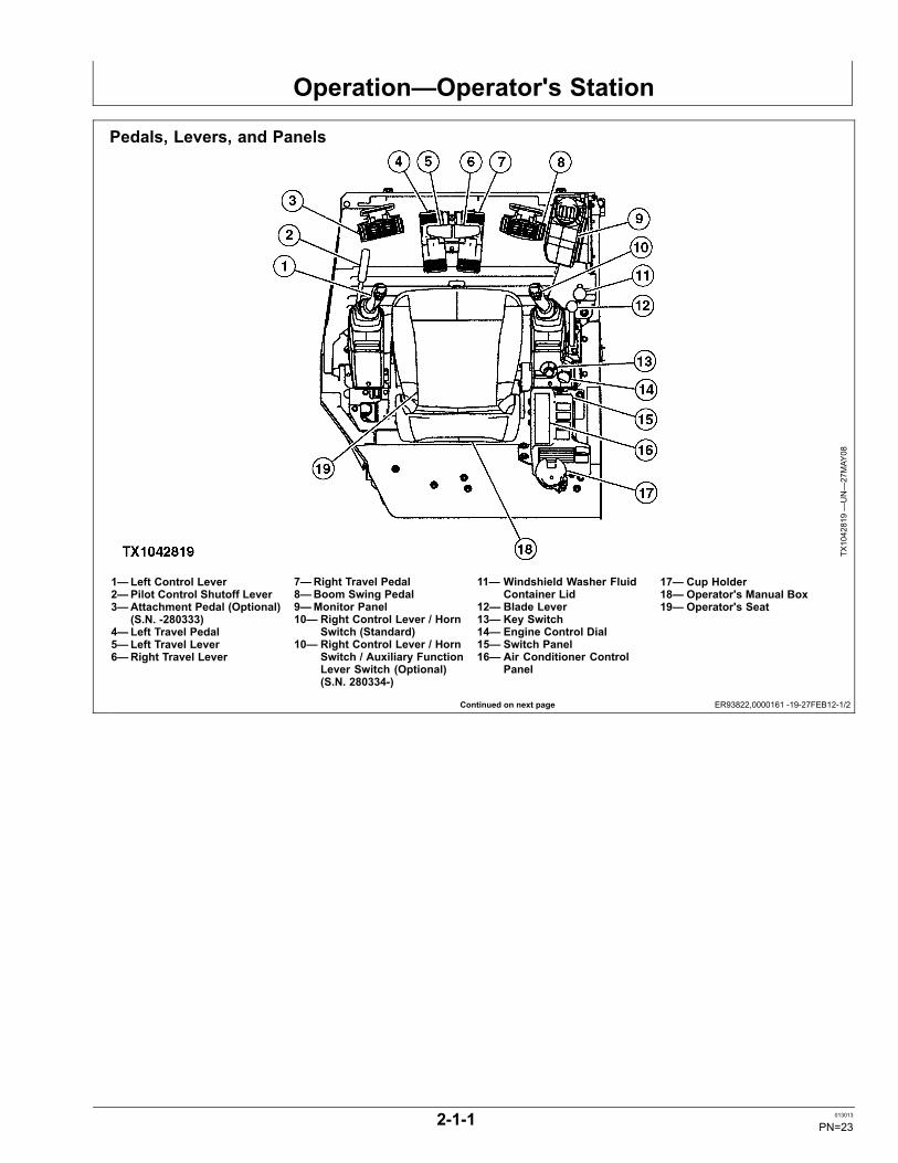
Pedals, Levers, and Panels
TX1042819—UN—27MAY
08
1—Left Control Lever2—Pilot Control Shutoff Lever3—Attachment Pedal (Optional)
(S.N. -280333)4—Left Travel Pedal5—Left Travel Lever6—Right Travel Lever
7—Right Travel Pedal8—Boom Swing Pedal9—Monitor Panel10— Right Control Lever / Horn
Switch (Standard)10— Right Control Lever / Horn
Switch / Auxiliary FunctionLever Switch (Optional)(S.N. 280334-)
11— Windshield Washer FluidContainer Lid
12— Blade Lever13— Key Switch14— Engine Control Dial15— Switch Panel16— Air Conditioner Control
Panel
17— Cup Holder18— Operator's Manual Box19— Operator's Seat
2-1-1 013013
PN=23

Operation—Operator's Station
ER93822,0000161 -19-27FEB12-2/2
TX1042828—UN—29MAY
08
Operator's Station—Ground View
TX1042832—UN—29MAY
08
Operator's Station—Right Side
12— Blade Lever15— Switch Panel17— Cup Holder20— Fuse Box21— Tool Box
22— Door Lock Release Lever23— Ash Tray24— Radio (Optional)25— Blade Angle Control Lever
(Optional)
TX1109207—UN—27FE
B12
Blade Angle Control Lever (Optional)
2-1-2 013013
PN=24
Operation—Operator's Station
ER93822,000002F -19-27FEB12-1/1
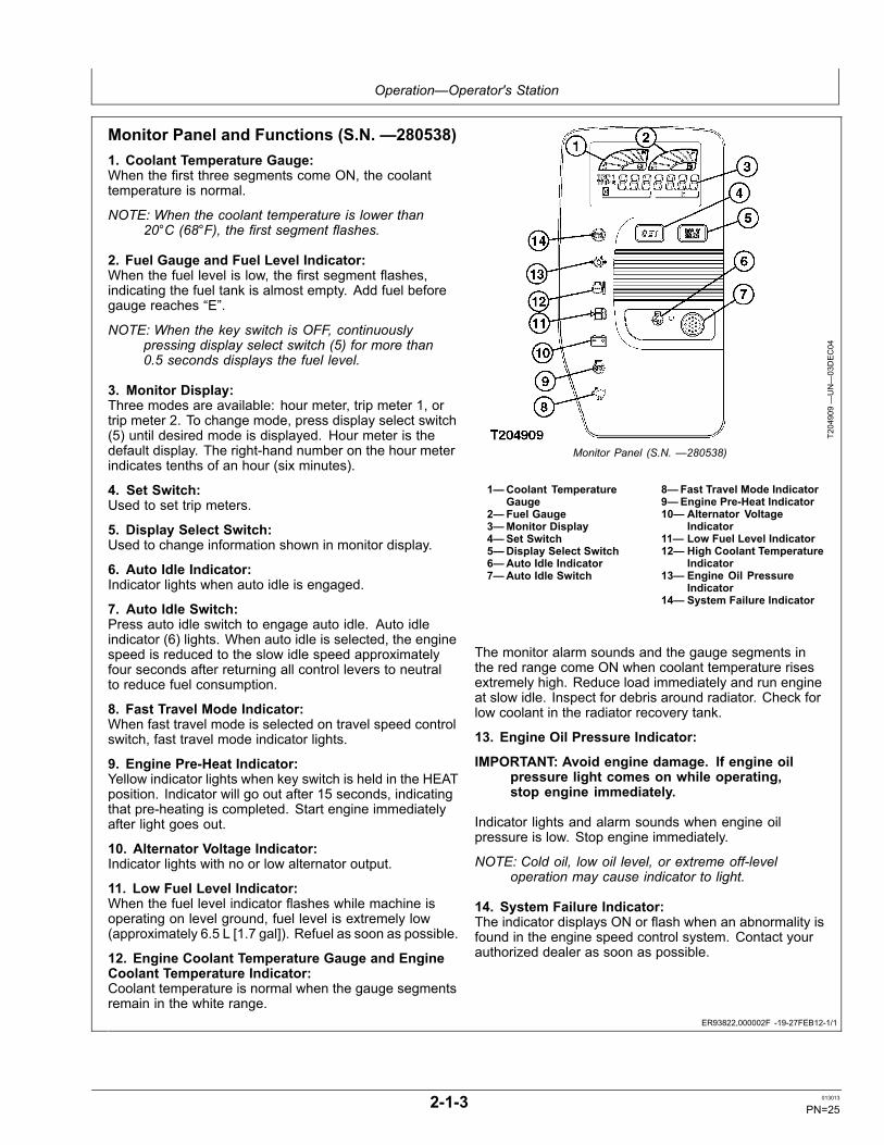
Monitor Panel and Functions (S.N. —280538)1. Coolant Temperature Gauge:When the first three segments come ON, the coolanttemperature is normal.
NOTE: When the coolant temperature is lower than20°C (68°F), the first segment flashes.
2. Fuel Gauge and Fuel Level Indicator:When the fuel level is low, the first segment flashes,indicating the fuel tank is almost empty. Add fuel beforegauge reaches “E”.
NOTE: When the key switch is OFF, continuouslypressing display select switch (5) for more than0.5 seconds displays the fuel level.
3. Monitor Display:Three modes are available: hour meter, trip meter 1, ortrip meter 2. To change mode, press display select switch(5) until desired mode is displayed. Hour meter is thedefault display. The right-hand number on the hour meterindicates tenths of an hour (six minutes).
4. Set Switch:Used to set trip meters.
5. Display Select Switch:Used to change information shown in monitor display.
6. Auto Idle Indicator:Indicator lights when auto idle is engaged.
7. Auto Idle Switch:Press auto idle switch to engage auto idle. Auto idleindicator (6) lights. When auto idle is selected, the enginespeed is reduced to the slow idle speed approximatelyfour seconds after returning all control levers to neutralto reduce fuel consumption.
8. Fast Travel Mode Indicator:When fast travel mode is selected on travel speed controlswitch, fast travel mode indicator lights.
9. Engine Pre-Heat Indicator:Yellow indicator lights when key switch is held in the HEATposition. Indicator will go out after 15 seconds, indicatingthat pre-heating is completed. Start engine immediatelyafter light goes out.
10. Alternator Voltage Indicator:Indicator lights with no or low alternator output.
11. Low Fuel Level Indicator:When the fuel level indicator flashes while machine isoperating on level ground, fuel level is extremely low(approximately 6.5 L [1.7 gal]). Refuel as soon as possible.
12. Engine Coolant Temperature Gauge and EngineCoolant Temperature Indicator:Coolant temperature is normal when the gauge segmentsremain in the white range.
T204909—UN—03DEC04
Monitor Panel (S.N. —280538)
1—Coolant TemperatureGauge
2—Fuel Gauge3—Monitor Display4—Set Switch5—Display Select Switch6—Auto Idle Indicator7—Auto Idle Switch
8—Fast Travel Mode Indicator9—Engine Pre-Heat Indicator10— Alternator Voltage
Indicator11— Low Fuel Level Indicator12— High Coolant Temperature
Indicator13— Engine Oil Pressure
Indicator14— System Failure Indicator
The monitor alarm sounds and the gauge segments inthe red range come ON when coolant temperature risesextremely high. Reduce load immediately and run engineat slow idle. Inspect for debris around radiator. Check forlow coolant in the radiator recovery tank.
13. Engine Oil Pressure Indicator:
IMPORTANT: Avoid engine damage. If engine oilpressure light comes on while operating,stop engine immediately.
Indicator lights and alarm sounds when engine oilpressure is low. Stop engine immediately.
NOTE: Cold oil, low oil level, or extreme off-leveloperation may cause indicator to light.
14. System Failure Indicator:The indicator displays ON or flash when an abnormality isfound in the engine speed control system. Contact yourauthorized dealer as soon as possible.
2-1-3 013013
PN=25

Operation—Operator's Station
ER93822,000002A -19-02SEP11-1/1
Monitor Panel and Functions (S.N. 280539— )1. Coolant Temperature Gauge:When the first three segments are illuminated, the coolanttemperature is normal.
NOTE: When the coolant temperature is lower than20°C (68°F), the first segment flashes.
2. Fuel Gauge:Position of segment illumination indicates fuel level. Addfuel before only the “E” segment of the gauge is illuminatedand/or the Low Fuel Level Indicator (5) is illuminated.
IMPORTANT: Avoid machine damage. If allsegments of the fuel gauge are illuminatedand flashing, immediately contact yourauthorized John Deere dealer.
3. Hour Meter:Numbers to the left of the decimal point indicate totalaccumulated operation hours since the machine beganworking. The number to the right of the decimal pointindicates tenths of an hour (six minutes).
4. Overheat Indicator:If the temperature of the coolant is extremely hot, thisindicator illuminates and a buzzer activates. Immediatelystop machine operation and reduce engine speed to slowidle speed to reduce coolant temperature.
5. Low Fuel Level Indicator:If this indicator illuminates while on level ground, theamount of fuel remaining in the fuel tank is 10.0 L (2.6 gal)or less. Add fuel to the fuel tank as soon as safely possible.
6. Alternator Indicator:This indicator illuminates when little or no alternator outputexists. If this indicator illuminates, examine components ofthe electrical system such as the alternator and/or battery.
7. Auto Idle Indicator:This indicator illuminates when the auto-idle switch onthe switch panel is activated.
8. Fast Travel Mode Indicator:This indicator illuminates when the fast mode side (rabbit)of the travel mode switch has been pressed.
9. System Failure Indicator:This indicator will illuminate and/or flash when there is astrong possibility of an irregularity in the engine controlsystem.
TX1096536A
—UN—25AUG11
Monitor Panel (S.N. 280539— )
1—Coolant TemperatureGauge
2—Fuel Gauge3—Hour Meter4—Overheat Indicator5—Low Fuel Level Indicator6—Alternator Indicator
7—Auto Idle Indicator8—Fast Travel Mode Indicator9—System Failure Indicator10— Preheat Indicator11— Engine Oil Pressure
Indicator
IMPORTANT: Avoid machine damage. If systemfailure indicator is illuminated, contact yourauthorized John Deere dealer immediately.
10. Preheat Indicator:This indicator illuminates when the machine determinesthat preheating is required.
11. Engine Oil Pressure Indicator:This indicator illuminates red when low engine oil pressureis present. The engine oil pressure warning buzzeractivates simultaneously with indicator.
IMPORTANT: Avoid machine damage. If engine oilpressure indicator is illuminated, stop theengine immediately. Examine the engineoil pressure system and engine oil level forthe presence of irregularities.
2-1-4 013013
PN=26

Operation—Operator's Station
ER93822,0000184 -19-02SEP11-1/1
Switch Panel and Functions (S.N. —280538)1. Travel Mode Switch:Press the top half of travel mode switch to select thefast travel mode. When the travel load becomes heavy,machine automatically selects slow travel mode. Pressthe bottom half of travel mode switch to select the slowtravel mode.
2. Work Light Switch:Press the top half of work light switch to illuminate lightson work lights located on boom and cab roof. Press thebottom half of switch to turn off lights.
3. Windshield Wiper/Washer Switch:The windshield wiper/washer switch has three positions:OFF, WIPER, WIPER/WASHER.
• OFF: Press bottom half of switch. Both windshieldwiper and washer do not operate.• WIPER: Toggle switch to center position. Windshieldwiper operates.• WIPER/WASHER: Press top half of switch. Bothwindshield wiper and washer operate.
4. Travel Alarm Cancel Switch:Press top half of travel alarm cancel switch to silencetravel alarm after initial 13 second alarm. Switch is resetwhen travel motion stops.
5. Power Mode Switch:The power mode switch has two positions: P, E
• P mode: Press bottom half of switch. Use whengeneral digging work is needed.
TX1042824—UN—28MAY
08
Switch Panel (S.N. —280538)
1—Travel Mode Switch2—Work Light Switch3—Windshield Wiper/Washer
Switch4—Travel Alarm Cancel Switch
5—Power Mode Switch6—Auxiliary Flow Control
Switch (if equipped)7—Air Conditioner Control
Panel
• E mode: Press top half of switch. Use to improve fuelefficiency and reduce noise level with a small differencein engine speed.
6. Auxiliary Flow Control Switch (if equipped):Press top half (LOW) of auxiliary flow control switch toplace hydraulic attachment in reduced flow rate mode.Press bottom half (HIGH) of switch to place hydraulicattachment in high flow rate mode.
2-1-5 013013
PN=27

Operation—Operator's Station
ER93822,0000031 -19-02SEP11-1/1
ER93822,000018E -19-29MAY08-1/1
Switch Panel and Functions (S.N. 280539— )1. Travel Mode Switch:Press the top half of travel mode switch to select thefast travel mode. When the travel load becomes heavy,machine automatically selects slow travel mode. Pressthe bottom half of travel mode switch to select the slowtravel mode.
2. Work Light Switch:Press the top half of work light switch to illuminate lightson work lights located on boom and cab roof. Press thebottom half of switch to turn off lights.
3. Windshield Wiper/Washer Switch:The windshield wiper/washer switch has three positions:OFF, WIPER, WIPER/WASHER.
• OFF: Press bottom half of switch. Both windshieldwiper and washer do not operate.• WIPER: Toggle switch to center position. Windshieldwiper operates.• WIPER/WASHER: Press top half of switch. Bothwindshield wiper and washer operate.
4. Auto-Idle Switch:Press the top half of auto-idle switch to activate auto-idleand illuminate auto-idle indicator on monitor panel. Whenauto-idle is activated, the engine speed will reduce toslow idle speed four seconds after releasing all controllevers (neutral position). Using auto-idle reduces fuelconsumption. Press the bottom half of the auto-idle switchto turn off auto-idle and auto-idle indicator.
5. Power Mode Switch:The power mode switch has two positions: P, E
TX1097291—UN—06OCT11
Switch Panel (S.N. 280539— )
1—Travel Mode Switch2—Work Light Switch3—Windshield Wiper/Washer
Switch4—Auto-Idle Switch
5—Power Mode Switch6—Auxiliary Flow Control
Switch (if equipped)7—Air Conditioner Control
Panel
• P mode: Press bottom half of switch. Use whengeneral digging work is needed.• E mode: Press top half of switch. Use to improve fuelefficiency and reduce noise level with a small differencein engine speed.
6. Auxiliary Flow Control Switch (if equipped):Press top half (LOW) of auxiliary flow control switch toplace hydraulic attachment in reduced flow rate mode.Press bottom half (HIGH) of switch to place hydraulicattachment in high flow rate mode.
Key SwitchRotate key switch cover (1) counterclockwise to uncoverkey switch (3).
To operate key switch, insert key (2) in key switch.
Key is inserted and removed with switch in the OFF (4)position.
Rotate key clockwise to Engine Preheat (5) position.Tractor accessories begin functioning with key in thisposition.
Rotate key clockwise to START position (6). Key willreturn to Engine ON (7) when released. Engine beginsfunctioning with key in this position.
TX1043058A
—UN—30MAY
08
1—Key Switch Cover2—Key3—Key Switch4—OFF
5—Engine Preheat6—START7—Engine ON
2-1-6 013013
PN=28

Operation—Operator's Station
ER93822,0000185 -19-31AUG11-1/1
ER93822,00001A4 -19-04JUN08-1/1
HornHorn button (1) is located on right control lever. Pressbutton to sound horn.
1—Horn Button
TX1042876A
—UN—27MAY
08
Standard Lever
TX1096906—UN—31AUG11
Auxiliary Function Lever (Optional) (S.N. 280334— )
Engine Speed Control KnobUse the engine speed control knob (1) to adjust enginespeed.
Turn knob clockwise to increase speed.
Turn knob counterclockwise to decrease speed.
1—Engine Speed Control Knob
TX1043350A
—UN—04JU
N08
2-1-7 013013
PN=29
Operation—Operator's Station
OUO1032,0001571 -19-25JAN07-1/1
ER93822,0000186 -19-02SEP11-1/1
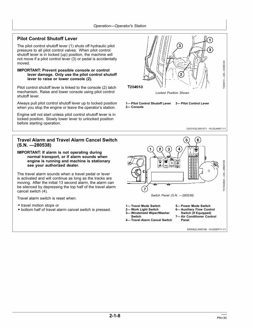
Pilot Control Shutoff LeverThe pilot control shutoff lever (1) shuts off hydraulic pilotpressure to all pilot control valves. When pilot controlshutoff lever is in locked (up) position, the machine willnot move if a pilot control lever (3) or pedal is accidentallymoved.
IMPORTANT: Prevent possible console or controllever damage. Only use the pilot control shutofflever to raise or lower console (2).
Pilot control shutoff lever is linked to the console (2) latchmechanism. Raise and lower console using pilot controlshutoff lever.
Always pull pilot control shutoff lever up to locked positionwhen you stop the engine or leave the operator’s station.
Engine will not start unless pilot control shutoff lever is inlocked position. Slowly lower lever to unlocked positionbefore starting operation.
T204913—UN—03DEC04
Locked Position Shown
1—Pilot Control Shutoff Lever2—Console
3—Pilot Control Lever
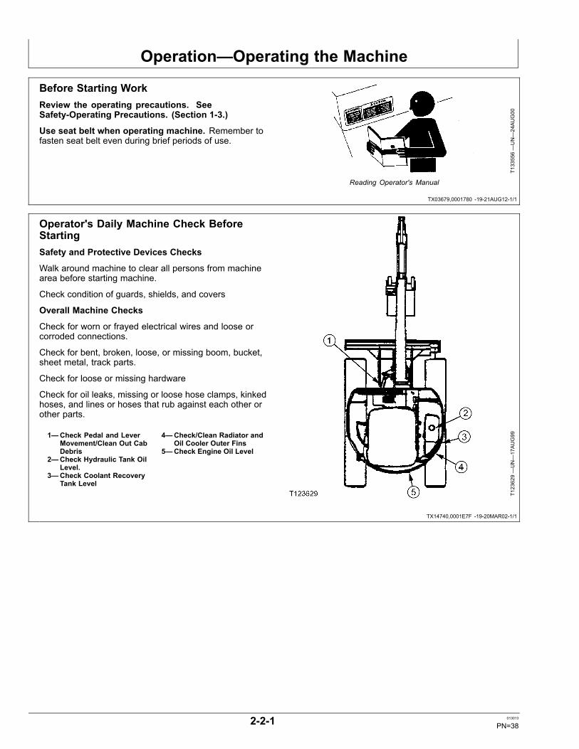
Travel Alarm and Travel Alarm Cancel Switch(S.N. —280538)IMPORTANT: If alarm is not operating during
normal transport, or if alarm sounds whenengine is running and machine is stationarysee your authorized dealer.
The travel alarm sounds when a travel pedal or leveris activated and will continue as long as the tracks aremoving. After the initial 13 second alarm, the alarm canbe silenced by depressing the top half of the travel alarmcancel switch (4).
Travel alarm switch is reset when:
• travel motion stops or• bottom half of travel alarm cancel switch is pressed.
TX1042824—UN—28MAY
08
Switch Panel (S.N. —280538)
1—Travel Mode Switch2—Work Light Switch3—Windshield Wiper/Washer
Switch4—Travel Alarm Cancel Switch
5—Power Mode Switch6—Auxiliary Flow Control
Switch (If Equipped)7—Air Conditioner Control
Panel
2-1-8 013013
PN=30

Operation—Operator's Station
Continued on next page ER93822,000018B -19-05JUN08-1/3
Cab Heater and Air Conditioner
TX1042837—UN—29MAY
08
TX1042838—UN—29MAY
08
1—Air Conditioner Control Panel 2—Right Rear Air Vent3—Right Front Air Vent
4—Foot Air Vent5—Right Front Air Vent
Air conditioner control panel (1) is used to heat and coolair flow within the cab.
2-1-9 013013
PN=31

Operation—Operator's Station
Continued on next page ER93822,000018B -19-05JUN08-2/3
TX1042839—UN—29MAY
08
Air Conditioner Panel Display
19 20 21 22
TX1042910—UN—28MAY
08
Air Vent Modes
CAUTION: Avoid personal injury and/ormachine damage. Keep fire hazards awayfrom the control panel.
IMPORTANT: Avoid compressor damage. Do notsuddenly increase engine speed.
1 — Vent Mode Switch: Press the vent mode switch untildesired mode (19-22) is displayed.
2 — Circulation and Fresh Air Mode Switch: Press toselect between recirculation and fresh air mode.Fresh air mode routes outside air into the cab.Circulation mode closes fresh air vent and circulatesair already in cab. Circulation mode is also indicatedon display when selected.
3 — Right Air Vent Indicator4 — Cool Temperature Indicator5 — Warm Temperature Indicator6 — Recirculation Indicator7 — Blower Speed Increase Switch: Press to increase
blower speed until desired speed is displayed.Blower speed can be set to one of four stagesranging from slow to fast. Speed will be indicated onair conditioner panel display.
8 — Air Conditioner Switch: Press to turn on airconditioner.
9 — Air Conditioner Power Switch: Press activate theair conditioner control panel.
10— Blower Speed Decrease Switch: Press to increaseblower speed until desired speed is displayed.Blower speed can be set to one of four stagesranging from slow to fast. Speed will be indicated onair conditioner panel display.
11 — A/C Indicator12 — Blower Speed Indicator13 — Blower Indicator14 — Temperature Increase Switch: Press to increase
set temperature in cab.15 — Temperature Decrease Switch Press to decrease
set temperature in cab.16 — Temperature Indicator17 — Vent Mode Indicator18 — Defroster Switch: Press to have air blow from all
vents in cab.
Heating Operation
1. Select desired vent mode (19-22). 22 is the modeusually used for the heating operation though anymode may be used.
2. Press the temperature decrease switch (15) to set thetemperature indicator toward the right.
3. Adjust inside cab temperature using temperaturecontrol switches (14 and 15).
4. Adjust blower speed using blower control switches (7and 10).
5. Operate circulation and fresh air mode switch tomaintain the air vent in the fresh air circulation mode.
When air conditioner switch (8) is activated during heatingoperation, air in the cab will be dehumidified.
Cooling Operation
1. Select desired vent mode (19-22). 20 is the modeusually used for the cooling operation though anymode may be used.
2. Press the temperature increase switch (14) to set thetemperature indicator toward the left.
3. Adjust inside cab temperature using temperaturecontrol switches (14 and 15).
4. Adjust blower speed using blower control switches (7and 10).
5. Operate circulation and fresh air mode switch tomaintain the air vent in the fresh air circulation mode.
When air conditioner switch (8) is activated during coolingoperation, cool air will blow out from all vents.
Defroster Operation
1. Select the right front vents by operating vent modeswitch (1). Vent mode (21) will be displayed in airconditioner control panel.
2. Adjust the louvers on right front vents as required.
2-1-10 013013
PN=32

Operation—Operator's Station
ER93822,000018B -19-05JUN08-3/3
ER93822,0000030 -19-02SEP11-1/1
3. Adjust blower speed using blower control switches (7and 10).
4. Adjust inside cab temperature using temperaturecontrol switches (14 and 15).
5. If windows become clouded and/or dehumidifying isneeded, turn air conditioner switch (8) on.
Setting Trip Meters (S.N. —280538)NOTE: Trip meters are preset to 10,000 hours
at the factory.
Trip meters can be set to notify the operator that a certainnumber of operation hours have passed. There aretwo meters, TRIP 1 and TRIP 2, and each one is setindividually.
To Set Trip Meters
1. Turn key switch ON.
2. Press display select switch (1) to display either tripmeter 1 (3) or trip meter 2 (4).
3. Press set switch (2) to select number of hours. Theavailable hour settings are:
• 50• 100• 150• 200• 250• 300• 400• 500• 750• 1000• 1250• 1500• 2000• 2500• 3000
4. Press display select switch (1) to set the trip meterhours.
5. When set hours reach zero, the trip meter displaywill flash. If trip meter is not reset at that time, thetrip meter hours will continue to display the operationhours with a minus (-) sign until trip meter is reset.
1—Display Select Switch2—Set Switch
3—TRIP 1 (trip meter 1)4—TRIP 2 (trip meter 2)
T205887—UN—07DEC04
T205888—UN—07DEC04
T205889—UN—07DEC04
2-1-11 013013
PN=33

Operation—Operator's Station
Continued on next page ER93822,000018A -19-28FEB12-1/2
Operating AM/FM Radio
TX1042841—UN—28MAY
08
Radio
1—Tone Control Knob2—FM Stereo Frequency
Indicator3—Radio Frequency Display4—Preset Display
5—Station Preset Buttons6—Tuning Increase Button7—Clock Button8—Tuning Decrease Button
9—Seek Button10— Auto-Store/Scan Preset
Button11— Band Button12— AM Frequency Indicator
13— FM Frequency Indicator14— Power Switch/Volume
Control Knob
Press power switch (1) to turn on radio, and repeatedlypress one of tuning buttons (6 and 8) until desired stationis reached. To preset a station, select the desired stationusing tuning buttons. Press and hold one of the stationpreset buttons (5) for more than 2 seconds until anelectronic tone is heard. The frequency of the presetstation is indicated on digital display (3).
1. Tone Control KnobRotate clockwise to intensify treble. Rotatecounterclockwise to reduce treble.
2. FM Stereo Frequency IndicatorIlluminates when an FM stereo radio wave frequency isselected.
3. Radio Frequency DisplayDisplays the radio frequency that is currently tuned.
4. Preset DisplayDisplays the station preset button number assigned to thefrequency that is currently tuned.
5. Station Preset ButtonsEach button stores one preset AM (MW) and FM station.Press button assigned to desired station.
6. Tuning Increase ButtonTap button to increase the frequency. Press and maintainpressure on button to continually increase radio frequency.Release button once desired radio frequency is displayed.
7. Clock ButtonPress button to display time. Press once more to displaythe current tuned frequency.
8. Tuning Decrease ButtonTap button to decrease the frequency. Press andmaintain pressure on button to continually decrease radiofrequency. Release button once desired radio frequencyis displayed.
9. Seek Button
Press to locate the next receivable station. The seekfunction stops when a station has been located.
10. Auto-Store/Scan Preset ButtonPress to receive the preset frequency station for every 5seconds sequentially. Once a desired station frequencyhas been found, press button again to interrupt the scanfeature and maintain radio frequency. Press and holdbutton for 2 seconds to automatically store the station.
11. Band ButtonPress this button to select AM (MW) or FM band.
12. AM Frequency IndicatorIlluminates when the AM (MW) band is selected.
13. FM Frequency IndicatorIlluminates when the FM band is selected.
14. Power Switch/Volume Control KnobWhen rotating knob, a click indicates radio power hasbeen turned on or off. Rotate knob clockwise to turn onradio and increase volume. Rotate knob counterclockwiseto decrease volume and turn radio off.
Radio Operation
1. Key switch must be in ON or START position.2. If radio is not already powered on, rotate power
switch/volume control knob clockwise until a click isheard.
3. Select station using:- tuning buttons;- station preset buttons;- auto-store/scan preset button; or- seek button
4. Rotate power switch/volume control knob to desiredvolume level.
5. Rotate tone control knob to preference.
To turn radio off, rotate power switch/volume control knobcounterclockwise until a click is heard.
2-1-12 013013
PN=34

Operation—Operator's Station
ER93822,000018A -19-28FEB12-2/2
ER93822,0000187 -19-27MAY08-1/1
NOTE: If battery power to the radio is disconnected,radio frequencies assigned to the stationpreset buttons will be lost.
Station Presetting Procedures
Manually Setting Station Preset Buttons
1. Key switch must be in ON or START position.2. If radio is not already powered on, rotate power
switch/volume control knob clockwise until a click isheard.
3. Rotate power switch/volume control knob to desiredvolume level.
4. Select station using:- tuning buttons or- seek button
5. To assign radio frequency, continuously press a stationpreset buttons for 2 seconds. Each station presetbutton may be assigned one AM (MW) station andone FM station. The preset number is displayed whenthe frequency is assigned.
After presetting has been completed, the preset frequencycan be changed if a preset button is pressed and heldfor 2 seconds.
Auto-Storing Procedure for Setting Station Preset Buttons
NOTE: Using the auto-storing procedure overwritesany frequencies previously assigned to astation preset button.
1. Key switch must be in ON or START position.2. If radio is not already powered on, rotate power
switch/volume control knob clockwise until a click isheard.
3. Rotate power switch/volume control knob to desiredvolume level.
4. Press auto-store/scan preset button for more than twoseconds. Radio automatically searches frequenciesfor receivable stations. The first six stations areassigned to the station preset buttons.
Preset Scanning
1. Key switch must be in ON or START position.2. If radio is not already powered on, rotate power
switch/volume control knob clockwise until a click isheard.
3. Rotate power switch/volume control knob to desiredvolume level.
4. Press and release auto-store/scan preset button.Radio automatically searches preset frequencies forreceivable stations for 5 seconds. Press and releaseauto-store/scan preset button a second time to resumenormal radio operation.
Setting the Clock
1. Key switch must be in ON or START position.2. If radio is not already powered on, rotate power
switch/volume control knob clockwise until a click isheard.
3. If necessary, press the clock button to display time.4. While maintaining pressure on the clock button, press
the tuning decrease button to change the hour display.Release buttons once desired hour is displayed.
5. While maintaining pressure on the clock button, pressthe tuning increase button to change the minutedisplay. Release buttons once desired minute isdisplayed.
Secondary Exit ToolIMPORTANT: FOR SECONDARY EXIT. Use secondary
exit tool (1) to break window. Alwayskeep tool in machine.
1—Secondary Exit Tool
TX1042852A
—UN—02JU
N08
2-1-13 013013
PN=35

Operation—Operator's Station
ER93822,0000188 -19-12JUN08-1/1
ER93822,000018C -19-28MAY08-1/1
Opening Front Upper (Secondary Exit)WindowOpening the Front Window
1. Disengage lock levers (1).
2. While holding the handles (2) on the window, pullwindow up and back until both lock levers are securelyengaged.
Switch (3) on front window prevents wiper from operatingwhen front window is opened. Before closing frontwindow, check that switch is OFF.
Closing the Front Window
CAUTION: Prevent possible injury from windowclosing. Front window comes down forcefully.Close window only when sitting in operator’sseat. Guide window down slowly.
1. Sit in operator's seat.
2. Disengage lock levers (1).
3. Using the handles (2), slowly guide window down andforward until both lock levers are engaged.
1—Lock lever (2 used)2—Handle (2 used)
3—Switch
TX1042901—UN—28MAY
08TX
1042902—UN—28MAY
08TX
1042903—UN—28MAY
08Removing Lower Front WindowNOTE: Upper front window must be raised before
lower front window can be removed.
While pulling in on window, raise window to remove.
NOTE: In cold weather, some operators may chooseto work with the top glass open and the bottomglass in place. This provides excellent visibilityand tends to hold the heat being circulatedaround the operator’s feet.
T136266—UN—18DEC00
2-1-14 013013
PN=36

Operation—Operator's Station
ER93822,0000166 -19-29MAY08-1/1
ER93822,000018D -19-28MAY08-1/1
ER93822,000019F -19-03JUN08-1/1
Opening Cab WindowTo open cab window, pull window bar (1) toward front ofmachine to release from latch. Continue pulling forwarduntil window is opened desired amount.
To close window, push window bar towards back ofmachine until window bar is latched.
1—Window bar
TX1043029A
—UN—30MAY
08
Door Release LeverIMPORTANT: Prevent machine damage from swinging
door. Ensure cab door is latched securelyif operating with door open.
The cab door can be locked in the open position. Openthe door all the way until cab door striker (1) is securedin cab door latch (2).
To release the door from locked position, push down oncab door release lever (3).
1—Cab Door Striker2—Cab Door Latch
3—Cab Door Release Lever
TX1042996A
—UN—30MAY
08T204914—UN—21DEC04
Adjusting Operator's SeatPress seat fore-aft slide lever (1) upward to allow seat toslide forward or rearward. Release lever when seat is atdesired position.
1—Fore-Aft Lever
TX1043247A
—UN—03JU
N08
2-1-15 013013
PN=37
Operation—Operating the Machine
TX03679,0001780 -19-21AUG12-1/1
TX14740,0001E7F -19-20MAR02-1/1
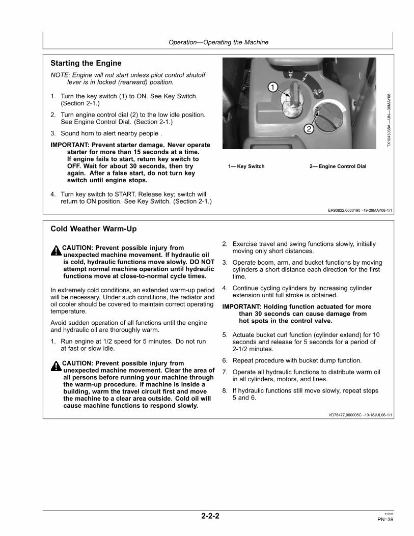
Before Starting WorkReview the operating precautions. SeeSafety-Operating Precautions. (Section 1-3.)
Use seat belt when operating machine. Remember tofasten seat belt even during brief periods of use.
T133556—UN—24AUG00
Reading Operator's Manual
Operator's Daily Machine Check BeforeStartingSafety and Protective Devices Checks
Walk around machine to clear all persons from machinearea before starting machine.
Check condition of guards, shields, and covers
Overall Machine Checks
Check for worn or frayed electrical wires and loose orcorroded connections.
Check for bent, broken, loose, or missing boom, bucket,sheet metal, track parts.
Check for loose or missing hardware
Check for oil leaks, missing or loose hose clamps, kinkedhoses, and lines or hoses that rub against each other orother parts.
1—Check Pedal and LeverMovement/Clean Out CabDebris
2—Check Hydraulic Tank OilLevel.
3—Check Coolant RecoveryTank Level
4—Check/Clean Radiator andOil Cooler Outer Fins
5—Check Engine Oil Level
T123629—UN—17AUG99
2-2-1 013013
PN=38
Operation—Operating the Machine
ER93822,0000190 -19-29MAY08-1/1
VD76477,000005C -19-18JUL06-1/1
Starting the EngineNOTE: Engine will not start unless pilot control shutoff
lever is in locked (rearward) position.
1. Turn the key switch (1) to ON. See Key Switch.(Section 2-1.)
2. Turn engine control dial (2) to the low idle position.See Engine Control Dial. (Section 2-1.)
3. Sound horn to alert nearby people .
IMPORTANT: Prevent starter damage. Never operatestarter for more than 15 seconds at a time.If engine fails to start, return key switch toOFF. Wait for about 30 seconds, then tryagain. After a false start, do not turn keyswitch until engine stops.
4. Turn key switch to START. Release key; switch willreturn to ON position. See Key Switch. (Section 2-1.)
TX1043068A
—UN—30MAY
08
1—Key Switch 2—Engine Control Dial
Cold Weather Warm-Up
CAUTION: Prevent possible injury fromunexpected machine movement. If hydraulic oilis cold, hydraulic functions move slowly. DO NOTattempt normal machine operation until hydraulicfunctions move at close-to-normal cycle times.
In extremely cold conditions, an extended warm-up periodwill be necessary. Under such conditions, the radiator andoil cooler should be covered to maintain correct operatingtemperature.
Avoid sudden operation of all functions until the engineand hydraulic oil are thoroughly warm.
1. Run engine at 1/2 speed for 5 minutes. Do not runat fast or slow idle.
CAUTION: Prevent possible injury fromunexpected machine movement. Clear the area ofall persons before running your machine throughthe warm-up procedure. If machine is inside abuilding, warm the travel circuit first and movethe machine to a clear area outside. Cold oil willcause machine functions to respond slowly.
2. Exercise travel and swing functions slowly, initiallymoving only short distances.
3. Operate boom, arm, and bucket functions by movingcylinders a short distance each direction for the firsttime.
4. Continue cycling cylinders by increasing cylinderextension until full stroke is obtained.
IMPORTANT: Holding function actuated for morethan 30 seconds can cause damage fromhot spots in the control valve.
5. Actuate bucket curl function (cylinder extend) for 10seconds and release for 5 seconds for a period of2-1/2 minutes.
6. Repeat procedure with bucket dump function.
7. Operate all hydraulic functions to distribute warm oilin all cylinders, motors, and lines.
8. If hydraulic functions still move slowly, repeat steps5 and 6.
2-2-2 013013
PN=39

Operation—Operating the Machine
OUO1032,0001578 -19-05DEC12-1/1
Travel Pedals and Levers
CAUTION: Prevent possible injury fromunexpected machine movement. Keepbystanders clear of machine when traveling.
The instructions below apply when the upperstructure isfacing forward and travel motors are to the rear of themachine. If the upperstructure is rotated to the rear andthe travel motors are to the front of the machine, themachine moves OPPOSITE to the direction described.
NOTE: Unfold foot pedals before using.
FORWARD TRAVEL: Push down on front (1) of bothpedals or push both levers forward (1).
REVERSE TRAVEL: Push down on rear (3) of both pedalsor pull both levers rearward (3).
NEUTRAL POSITION (2): Travel brakes will automaticallystop and hold the machine.
RIGHT TURN: Push down on front of left pedal or pushleft lever forward.
LEFT TURN: Push down on front of right pedal or pushright lever forward.
SHORT TURN (COUNTERROTATE): Push down thefront of one pedal and the rear of the other or push onelever forward and pull the other rearward.
CAUTION: Prevent possible injury from machinetipping. Operate control pedals or levers slowlywhen traveling down a slope.
TRAVELING DOWN A SLOPE: Operate control pedals orlevers slowly when traveling down a slope.
COLD WEATHER OPERATION: Travel pedal and leverdampers are provided for smooth control. In extremely
T204926—UN—07DEC04
Levers
T204927—UN—07DEC04
Pedals and Levers
1—Forward Travel2—Neutral Position
3—Reverse Travel
cold weather, pedal or lever effort will increase. Operatepedals or levers several times with pilot control shutofflever in locked position.
2-2-3 013013
PN=40

Operation—Operating the Machine
OUO1032,0001579 -19-18JUL06-1/1
Control Lever Pattern Operation
CAUTION: Never place any part of body beyondwindow frame to avoid serious crushing injuryfrom boom. Boom could lower if the control leveris accidentally bumped or otherwise engaged.Immediately replace a missing or broken window.
Never place any part of the body beyond the windowframe. Replace missing or broken windows (if equipped)immediately.
CAUTION: Prevent injury from unexpected controllever function. Be aware of the control leverpattern used on the machine before operating.
A label showing each control lever pattern operation isprovided on the operator's right.
Check the pattern on the label and then carefully operatethe machine to verify the selected pattern is correct. (SeeControl Lever Pattern Conversion in this section.)
Control levers return to neutral when released. Functionswill stop and remain positioned. The parking brake forswing and travel will also engage.
1—Arm Out2—Arm In3—Swing Left4—Swing Right
5—Boom Down6—Boom Up7—Bucket Load8—Bucket Dump
T204929—UN—07DEC04
Excavator Control Lever Pattern
T204930—UN—07DEC04
Backhoe Control Lever Pattern
T204931—UN—07DEC04
Boom, Arm, Bucket Movement
2-2-4 013013
PN=41

Operation—Operating the Machine
ER93822,0000196 -19-02JUN08-1/1
Control Lever Pattern ConversionThe machine pilot control levers can be changed fromthe standard “Excavator” control pattern to a “Backhoe”control pattern. To change control pattern:
1. Park machine on a level surface.
2. Run engine at slow idle speed without load for 3minutes.
3. Turn key switch to OFF to stop engine. Remove keyfrom switch.
4. Pull pilot shutoff lever up to the locked position.
5. Control pattern selector lever (1) is located under seat.Open panel (2) to access selector lever.
6. Rotate selector lever to desired control pattern position.(Lever must be aligned with arrow on selected controlpattern and detented in order to function as expected.)
7. Close panel.
8. Verify selected pattern is visible through sight hole.
1—Control Pattern SelectorLever
2—Panel
3—Excavator Position4—Backhoe Position
TX1043171A
—UN—02JU
N08
TX1043172A
—UN—02JU
N08
2-2-5 013013
PN=42

Operation—Operating the Machine
OU90V02,0000145 -19-09JAN09-1/1
Operating Angle Blade—If EquippedPull angle blade lever (3) rearward to raise angle blade (4).
Push angle blade lever forward to lower angle blade (5).
Push angle left turn switch (1) to angle blade left.
Push angle right turn switch (2) to angle blade right.
1—Angle Left Turn Switch2—Angle Right Turn Switch3—Angle Blade Lever
4—Angle Blade Raise5—Angle Blade Lower
TX1053270—UN—17DEC08
TX1053272—UN—17DEC08
2-2-6 013013
PN=43
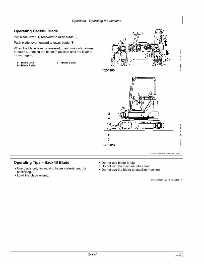
Operation—Operating the Machine
OUO1032,000157C -19-16NOV04-1/1
ER93822,00001A5 -19-04JUN08-1/1
Operating Backfill BladePull blade lever (1) rearward to raise blade (2).
Push blade lever forward to lower blade (3).
When the blade lever is released, it automatically returnsto neutral, keeping the blade in position until the lever ismoved again.
1—Blade Lever2—Blade Raise
3—Blade Lower
T204965—UN—07DEC04
T205092—UN—01DEC04
Operating Tips—Backfill Blade• Use blade only for moving loose material and forbackfilling.• Load the blade evenly.
• Do not use blade to dig.• Do not run the machine into a load.• Do not use the blade to stabilize machine.
2-2-7 013013
PN=44

Operation—Operating the Machine
ER93822,000002E -19-29AUG11-1/1
Auxiliary Pedal—If Equipped (S.N. —280333)
CAUTION: Avoid injury from unexpected machinemovement. Keep pedal cover in locked positionwhen not using auxiliary pedal.
1. Lift pedal cover (1) to unlock auxiliary pedal (2).
2. Push on the right or left side of the auxiliary pedal tooperate the front-end attachment. (See PositioningAuxiliary Line Selector Valve below for single anddouble activation.)
3. Lower pedal cover to lock auxiliary pedal.
T204935—UN—07DEC04
1—Pedal Cover 2—Auxiliary Pedal
2-2-8 013013
PN=45

Operation—Operating the Machine
ER93822,000002B -19-29AUG11-1/1
Auxiliary Function Lever Switch—If Equipped(S.N. 280334— )
CAUTION: Avoid personal injury or death. Neverattempt to use this switch for purposes otherthan to operate the attachment installed onthis machine. Do not attempt to modify theswitch performance and/or shape.
CAUTION: Avoid personal injury and/or machinedamage. Before operating this switch, besure to thoroughly read the attachment’soperator manual and check the movement ofeach function in a safe location.
CAUTION: Avoid personal injury and/ormachine damage. Contact the attachment’smanufacturer and sales company aboutrequirements concerning the proper installationand operation of the attachment.
1. Move slide switch (2) of the right control lever (1) toeither side to operate the installed attachment.
2. When pressure switch (3) is pressed, the installedattachment will operate as though the slide switchhas been moved to the left side of the slide switch. Ifboth slide switch and pressure switch are operatedsimultaneously, the pressure switch has priority.
NOTE: The pressure switch operation is convenientwhen using a hydraulic breaker.
1—Right Control Lever2—Slide Switch
3—Pressure Switch
TX1096566A
—UN—25AUG11
Location of Auxiliary Function Lever Switch
TX1096567A
—UN—25AUG11
Auxiliary Function Lever Switches
2-2-9 013013
PN=46

Operation—Operating the Machine
ER93822,00001BA -19-10JUN08-1/1
ER93822,0000197 -19-11JUN08-1/1
Positioning Auxiliary Line Selector ValveIMPORTANT: Prevent possible machine damage.
Stop the engine and move pilot control shutofflever to locked (rearward) position beforemoving the selector valve.
1. Stop engine.
2. Remove plug (1) to access selector valve. Selectorvalve must be positioned according to the type ofattachment to be operated:
• Position 2: Operating a breaker or other singleactuating cylinder attachment requiring only ON/OFFoperation.• Position 3: Operating a crusher or other doubleactuating cylinder attachment requiring two actionssuch as OPEN/CLOSE operation.
1—Selector Valve Plug2—ON/OFF (for single
actuating cylinderattachment)
3—OPEN/CLOSE (for doubleactuating cylinderattachment)
TX1043761A
—UN—10JU
N08
TX1043762A
—UN—10JU
N08
Operating In Water and MudBe careful not to operate the machine in water or mudabove the upper track shoe surface (1), causing the swingbearing and rotary manifold to be submerged.
SpecificationUpper Track ShoeSurface (Operable WaterDepth)—Distance........................................................................ 545 mm
22 in.
If the swing bearing and rotary manifold are submerged,remove cover from underneath center of machine.Remove drain plug to drain water and mud.
Clean swing gear area. Install plug and cover. Greaseswing bearing and grease swing bearing gear. (SeeSections 3-6 and 3-7.)
T121704—UN—08JU
N99
1—Upper Track Shoe Surface
2-2-10 013013
PN=47

Operation—Operating the Machine
TX03679,0001782 -19-24JAN07-1/1
TX14740,0001EF2 -19-09JUL02-1/1
Driving Up a Steep or Slippery Slope
CAUTION: Prevent possible injury from machinerollover. Use this technique only on a short slope.Machine depends on support of boom/arm/bucketduring entire procedure until machine reachestop of slope. Repositioning the bucket duringthis procedure is NOT recommended. DO NOTswing upperstructure during this procedure. DONOT reposition bucket during this procedure.
1. Wear seat belt.
2. Position undercarriage so travel motors will be onuphill end of machine.
3. Push bucket into the ground.
4. When boom is on uphill end of machine: Pull machineusing boom and arm cylinder to help travel motors.
When boom is on downhill end of machine: Pushmachine using boom and arm cylinder to help travelmotors.
Lifting
CAUTION: Prevent possible injury whenlifting. Observe these rules when liftingwith your machine:
• Never use machine to lift people• Do not exceed lift capacity limits• Keep everyone clear of raised loads• Never attach sling or chain to bucket teeth• Use tether lines to guide loads• Use hand signals to communicate with others
1. Use proper rigging to attach and stabilize loads.
2. Without bucket loop: Curl bucket and retract arm.Fasten sling or chain to bucket pivot pin.
With bucket loop: Curl bucket and retract arm. Fastensling or chain to bucket loop.
3. Check stability by carefully doing a trial lift:
• Raise load just off of ground• Swing load all the way to one side• Move load slowly away from machine• Lower load immediately if machine is not stable
2-2-11 013013
PN=48

Operation—Operating the Machine
ER93822,00001A6 -19-28FEB12-1/1
ER93822,0000199 -19-02JUN08-1/1
Lowering Boom With Engine StoppedWhen the engine stops during operation, the boom cannotbe lowered using the pilot controller because there is nopilot pressure to move the boom valve spool.
1. Lift cab access to boom up circuit relief valve (1).
2. Make an alignment mark on the adjusting screw (2),nut (3), and relief valve body.
3. Loosen nut using a 14 mm wrench.
CAUTION: Prevent possible injury fromunexpected machine movement. Clear allpersons from the area before lowering the boom.
Loosening the boom up circuit relief valveadjusting screw more than two turns mayresult in the release of the pilot spring andoil from the circuit relief valve.
4. Slowly turn the adjusting screw out approximately1-1/2 turns to lower the boom.
5. After bucket is on the ground, turn the adjusting screwin to its original setting. Hold the screw and tightenthe nut.
1—Boom Up Circuit ReliefValve
2—Adjusting Screw
3—Nut
TX1043367—UN—05JU
N08
T204482—UN—17NOV04
Parking MachineIMPORTANT: During freezing weather, prevent
damage to undercarriage components fromfrozen mud and dirt. Machine must beparked on a solid level surface to preventtracks freezing in the ground.
1. Park machine on a level surface.
2. Lower the bucket and blade to the ground.
3. Run engine at slow idle speed without load for 3minutes.
4. Turn key switch to OFF. Remove key from switch.
5. Pull pilot control shutoff lever (1) to locked position.
6. Close windows and cab door.
7. Lock all access doors and compartments.
T204913—UN—03DEC04
Lever in Locked Position
1—Pilot Control Shut-Off Lever2—Console
3—Pilot Control Levers
2-2-12 013013
PN=49

Operation—Operating the Machine
VD76477,000014E -19-18JUL06-1/1
ER93822,000016B -19-20MAY08-1/1
Loading and Unloading for Transport
CAUTION: Avoid possible injury from unexpectedmachine movement. Use extra care to prevent tipover or unexpected movement when loading andunloading machine for transport. Observe theserules when loading and unloading machine:
• Always wear seat belt.• Locate trailer on a level and stable surface.Chock trailer wheels.• Use loading ramps. Keep ramps at a lowangle and firmly attached to trailer.
1. When loading machine, use bucket for support withangle of arm to boom at 90°.
IMPORTANT: Prevent machine or trailer damage. DONOT allow machine or bucket to impact trailer.
2. Position machine on trailer (centerline of machine overcenterline of trailer).
3. Lower boom until the bucket is at rest on trailer bed.
4. Stop engine.
T121194—UN—21APR99
5. Secure the bucket, blade and track frame to the trailerwith chains or cables. Do not allow the chains orcables to come into contact with the rubber tracks,hydraulic hoses or hydraulic lines.
6. Verify the overall height of the load on the trailer.
7. When unloading machine, use bucket for support withangle of arm to boom at 90°.
Towing Machine
CAUTION: Prevent possible injury from towline breaking. Do not tow machine withdamaged chains, frayed cables, slings,straps or wire tow lines.
Always wear gloves when handling cables,straps or wire tow lines.
Attach tow line to track frame of machine being towed,and of towing machine. Slowly tow machine.
T121986—UN—24JU
N99
2-2-13 013013
PN=50

Operation—Operating the Machine
ER93822,0000198 -19-27FEB12-1/1
Lifting Machine
CAUTION: Prevent possible injury fromunexpected machine movement when liftingthe machine. Check lifting capacity of cranebefore lifting the excavator. Lift load onlyas high as necessary.
Keep all people clear of raised load.
1. Swing the upperstructure so the blade is positionedto the rear.
2. Lower the blade to the ground.
3. Fully extend the boom, arm, and bucket cylinders.
4. Position the boom straight ahead of the upperstructure.
5. Turn key switch to OFF. Remove key from switch.
6. Pull the pilot control shutoff lever to the locked position.
7. Attach cables to the eye plates, one on the boom andtwo on the blade.
8. Slowly lift the machine.Specification
Boom Eye Lifting Point toBranch Point—Distance............................................................ 1700 mm
67 inBlade Eye Lifting Point toBranch Point—Distance............................................................ 4200 mm
165 in
For information concerning operating weights of machine,see Machine Specifications. (Sections 4-6.)
T121196—UN—20APR99
1—Distance from Boom EyeLifting Point to BranchPoint
2—Distance from Blade EyeLifting Point to BranchPoint
2-2-14 013013
PN=51
Maintenance—Machine
DX,FUEL1 -19-11APR11-1/1
Diesel Fuel
Consult your local fuel distributor for properties of thediesel fuel available in your area.
In general, diesel fuels are blended to satisfy the lowtemperature requirements of the geographical area inwhich they are marketed.
Diesel fuels specified to EN 590 or ASTM D975 arerecommended. Renewable diesel fuel produced byhydrotreating animal fats and vegetable oils is basicallyidentical to petroleum diesel fuel. Renewable diesel thatmeets EN 590 or ASTM D975 is acceptable for use at allpercentage mixture levels.
Required Fuel Properties
In all cases, the fuel shall meet the following properties:
Cetane number of 43 minimum. Cetane number greaterthan 47 is preferred, especially for temperatures below–20°C (–4°F) or elevations above 1500 m (5000 ft.).
Cold Filter Plugging Point (CFPP) should be at least 5°C(9°F) below the expected lowest temperature or CloudPoint below the expected lowest ambient temperature.
Fuel lubricity should pass a maximum scar diameter of0.45 mm as measured by ASTM D6079 or ISO 12156-1.
Diesel fuel quality and sulfur content must comply withall existing emissions regulations for the area in whichthe engine operates. DO NOT use diesel fuel with sulfurcontent greater than 10 000 mg/kg (10 000 ppm).
Sulfur content for Interim Tier 4 and Stage III B engines
• Use ONLY ultra low sulfur diesel (ULSD) fuel with amaximum of 15 mg/kg (15 ppm) sulfur content.
Sulfur Content for Tier 3 and Stage III A Engines
• Use of diesel fuel with sulfur content less than 1000mg/kg (1000 ppm) is RECOMMENDED• Use of diesel fuel with sulfur content 1000–5000 mg/kg(1000–5000 ppm) REDUCES oil and filter changeintervals.
• BEFORE using diesel fuel with sulfur content greaterthan 5000 mg/kg (5000 ppm), contact your John Deeredealer
Sulfur Content for Tier 2 and Stage II Engines
• Use of diesel fuel with sulfur content less than 500mg/kg (500 ppm) is RECOMMENDED.• Use of diesel fuel with sulfur content 500–5000 mg/kg(500–5000 ppm) REDUCES the oil and filter changeinterval• BEFORE using diesel fuel with sulfur content greaterthan 5000 mg/kg (5000 ppm), contact your John Deeredealer
Sulfur Content for Other Engines
• Use of diesel fuel with sulfur content less than 5000mg/kg (5000 ppm) is recommended.• Use of diesel fuel with sulfur content greater than 5000mg/kg (5000 ppm) REDUCES the oil and filter changeintervals.
IMPORTANT: Do not mix used diesel engine oil or anyother type of lubricating oil with diesel fuel.
IMPORTANT: Improper fuel additive usage maycause damage on fuel injection equipmentof diesel engines.
3-1-1 013013
PN=52
Maintenance—Machine
Continued on next page DX,FUEL7 -19-29AUG12-1/2
Biodiesel Fuel
Biodiesel fuel is comprised of mono-alkyl esters of longchain fatty acids derived from vegetable oils or animalfats. Biodiesel blends are biodiesel mixed with petroleumdiesel fuel on a volume basis.
Before using fuel containing biodiesel, review theBiodiesel Use Requirements and Recommendations inthis Operator’s Manual.
Environmental laws and regulations can encourage orprohibit the use of biofuels. Operators should consultwith appropriate governmental authorities prior to usingbiofuels.
All John Deere Engines with Exhaust Filter (Released2011 and After)
While 5% blends (B5) are preferred, biodieselconcentrations up to a 20% blend (B20) in petroleumdiesel fuel can be used. Biodiesel blends up to B20can be used ONLY if the biodiesel (100% biodiesel orB100) meets ASTM D6751, EN 14214, or equivalentspecification. Expect a 2% reduction in power and a 3%reduction in fuel economy when using B20.
Biodiesel concentrations above B20 can harm theengine’s emission control systems and should not beused. Risks include, but are not limited to, more frequentstationary regeneration, soot accumulation, and increasedintervals for ash removal.
John Deere approved fuel conditioners, which containdetergent and dispersant additives, are required whenusing B20, and are recommended when using lowerbiodiesel blends.
All John Deere Engines Excluding Exhaust Filter(Primarily Released Prior to 2012)
While 5% blends (B5) are preferred, biodieselconcentrations up to a 20% blend (B20) in petroleumdiesel fuel can be used. Biodiesel blends up to B20can be used ONLY if the biodiesel (100% biodiesel orB100) meets ASTM D6751, EN 14214, or equivalentspecification. Expect a 2% reduction in power and a 3%reduction in fuel economy when using B20.
These John Deere engines can operate on biodieselblends above B20 (up to 100% biodiesel). Operate atlevels above B20 ONLY if the biodiesel is permitted by lawand meets the EN 14214 specification (primarily availablein Europe). Engines operating on biodiesel blends aboveB20 might not fully comply with or be permitted by allapplicable emissions regulations. Expect up to a 12%reduction in power and an 18% reduction in fuel economywhen using 100% biodiesel.
John Deere approved fuel conditioners, which containdetergent and dispersant additives, are required whenusing B20, and are recommended when using lowerbiodiesel blends.
Biodiesel Use Requirements and Recommendations
The petroleum diesel portion of all biodiesel blends mustmeet the requirements of ASTM D975 (US) or EN 590(EU) commercial standards.
Biodiesel users in the U.S. are strongly encouraged topurchase biodiesel blends from a BQ-9000 CertifiedMarketer and sourced from a BQ-9000 AccreditedProducer (as certified by the National Biodiesel Board).Certified Marketers and Accredited Producers can befound at the following website: http://www.bq9000.org.
Biodiesel contains residual ash. Ash levels exceeding themaximums allowed in either ASTM D6751 or EN14214can result in more rapid ash loading and require morefrequent cleaning of the Exhaust Filter (if present).
The fuel filter can require more frequent replacement,when using biodiesel fuel, particularly if switching fromdiesel. Check engine oil level daily prior to starting engine.A rising oil level can indicate fuel dilution of the engine oil.Biodiesel blends up to B20 must be used within 90 daysof the date of biodiesel manufacture. If used, biodieselblends above B20 must be used within 45 days from thedate of biodiesel manufacture.
When using biodiesel blends up to B20, the followingmust be considered:
• Cold weather flow degradation• Stability and storage issues (moisture absorption,microbial growth)• Possible filter restriction and plugging (usually a problemwhen first switching to biodiesel on used engines.)• Possible fuel leakage through seals and hoses(primarily an issue with older engines)• Possible reduction of service life of engine componentsRequest a certificate of analysis from your fuel distributorto ensure that the fuel is compliant with the specificationsprovided in this Operator’s Manual.
Consult your John Deere dealer for approved fuelconditioners to improve storage and performance withbiodiesel fuels.
The following must also be considered if using biodieselblends above B20:
• Possible coking or blocked injector nozzles, resulting inpower loss and engine misfire if John Deere approvedfuel conditioners are not used• Possible crankcase oil dilution (requiring more frequentoil changes)• Possible lacquering or seizure of internal components• Possible formation of sludge and sediments• Possible thermal oxidation of fuel at elevatedtemperatures• Possible compatibility issues with other materials(including copper, lead, zinc, tin, brass, and bronze)used in fuel handling equipment• Possible reduction in water separator efficiency• Possible damage to paint if exposed to biodiesel
3-1-2 013013
PN=53

Maintenance—Machine
DX,FUEL7 -19-29AUG12-2/2
DX,FUEL6 -19-14APR11-1/1
DX,FUEL4 -19-14APR11-1/1
• Possible corrosion of fuel injection equipment• Possible elastomeric seal and gasket materialdegradation (primarily an issue with older engines)• Possible high acid levels within fuel system• Because biodiesel blends above B20 contain moreash, using blends above B20 can result in more rapidash loading and require more frequent cleaning of theExhaust Filter (if present)
IMPORTANT: Raw pressed vegetable oils areNOT acceptable for use as fuel in anyconcentration in John Deere engines. Theiruse could cause engine failure.
Testing Diesel FuelA fuel analysis program can help to monitor the qualityof diesel fuel. The fuel analysis can provide criticaldata such as cetane number, fuel type, sulfur content,water content, appearance, suitability for cold weather
operations, bacteria, cloud point, acid number, particulatecontamination, and whether the fuel meets specification.
Contact your John Deere dealer for more information ondiesel fuel analysis.
Handling and Storing Diesel Fuel
CAUTION: Reduce the risk of fire. Handle fuelcarefully. DO NOT fill the fuel tank when engineis running. DO NOT smoke while you fill thefuel tank or service the fuel system.
Fill the fuel tank at the end of each day's operation toprevent water condensation and freezing during coldweather.
Keep all storage tanks as full as practicable to minimizecondensation.
Ensure that all fuel tank caps and covers are installedproperly to prevent moisture from entering. Monitor watercontent of the fuel regularly.
When using biodiesel fuel, the fuel filter may require morefrequent replacement due to premature plugging.
Check engine oil level daily prior to starting engine. Arising oil level may indicate fuel dilution of the engine oil.
IMPORTANT: The fuel tank is vented through thefiller cap. If a new filler cap is required, alwaysreplace it with an original vented cap.
When fuel is stored for an extended period or if there is aslow turnover of fuel, add a fuel conditioner to stabilize thefuel and prevent water condensation. Contact your fuelsupplier for recommendations.
3-1-3 013013
PN=54

Maintenance—Machine
DW90712,00001C3 -19-18JUL06-1/1
DX,ENOIL11 -19-11APR11-1/1
Alternative and Synthetic Lubricants
Conditions in certain geographical areas may requirelubricant recommendations different from those printedin this manual. Some John Deere brand coolants andlubricants may not be available in your location.
Synthetic lubricants may be used if they meet theperformance requirements as shown in this manual.
The temperature limits and service intervals shown in thismanual apply to both conventional and synthetic oils.
Re-refined base stock products may be used if thefinished lubricant meets the performance requirements.
If alternative hydraulic oils are required the hydraulicsystem needs to be completely flushed. This may requirelarge amounts of oil to properly drain previous product.
NOTE: The following alternative oils could be used iffactory fill has been completely flushed out.
Texaco Rando 46
Texaco Rando 32
Mobil DTE25-46
Mobil DTE25-32
Shell Tellus 46
Shell Tellus 32
Consult your authorized dealer to obtain specificinformation and recommendations.
IMPORTANT: Avoid mixing different brands ortypes of oils. Oil manufacturers blend basestock and additives to create their oils and tomeet certain specifications and performancerequirements. Mixing different oils can interferewith proper functioning of these formulationsand degrade lubricant performance.
This excavator is factory filled with 46HN extended lifezinc-free hydraulic oil. Avoid servicing this excavator withproducts that do not meet this specification. If oils havebeen mixed or if alternate service oils are desired, thecomplete hydraulic system needs to be totally flushed byan authorized dealer.
Diesel Engine OilUse oil viscosity based on the expected air temperaturerange during the period between oil changes.
John Deere Plus-50™ II oil is preferred.
John Deere Plus-50™ is also recommended.
Other oils may be used if they meet one or more of thefollowing:
• John Deere Torq-Gard™• API Service Category CJ-4• API Service Category CI-4 PLUS• API Service Category CI-4• ACEA Oil Sequence E9• ACEA Oil Sequence E7• ACEA Oil Sequence E6• ACEA Oil Sequence E5• ACEA Oil Sequence E4
Multi-viscosity diesel engine oils are preferred.
Diesel fuel quality and fuel sulfur content must complywith all existing emissions regulations for the area inwhich the engine operates.
DO NOT use diesel fuel with sulfur content greater than10 000 mg/kg (10 000 ppm).
SA
E 1
5W-4
0
SA
E 1
0W-4
0
SA
E 1
0W-3
0
SA
E 0
W-4
0
SA
E 5
W-3
0
50 Co
40 Co
30 Co
20 Co
10 Co
0 C o
-10 Co
-20 Co
-30 Co
-40 Co
122 Fo
50 Fo
32 Fo
14 Fo
-4 Fo
-22 Fo
-40 Fo
104 Fo
68 Fo
86 Fo
TS1691
—UN—18JU
L07
Oil Viscosities for Air Temperature Ranges
Plus-50 is a trademark of Deere & CompanyTorq-Gard is a trademark of Deere & Company
3-1-4 013013
PN=55

Maintenance—Machine
DX,ENOIL13 -19-03AUG09-1/1
Diesel Engine Oil and Filter Service Intervals
The oil and filter service intervals in the following tableshould be used as guidelines. Actual service intervalsalso depend on operation and maintenance practices. Itis suggested to use oil analysis to determine the actualuseful life of the oil and to aid in selection of the properoil and filter service interval.
Oil and filter service intervals are based on a combinationof oil pan capacity, type of engine oil and filter used, andsulfur content of the diesel fuel.
Diesel fuel sulfur level will affect engine oil and filterservice intervals. Higher fuel sulfur levels reduce oil andfilter service intervals as shown in the table.
• Use of diesel fuel with sulfur content less than 0.10%(1000 mg/kg) is strongly recommended.• Use of diesel fuel with sulfur content 0.10% (1000mg/kg) to 0.50% (5000 mg/kg) may result in REDUCEDoil and filter change intervals as shown in the table.• BEFORE using diesel fuel with sulfur content greaterthan 0.50% (5000 mg/kg), contact your John Deeredealer.• DO NOT use diesel fuel with sulfur content greater than1.00% (10 000 mg/kg).
IMPORTANT: When using biodiesel blends greaterthan B20, reduce the oil and filter serviceinterval by 50% or monitor engine oil basedon test results from Oilscan.
Oil types in the table include:
• John Deere Plus-50™ II and John Deere Plus-50• “Other Oils” include John Deere Torq-Gard Supreme™,API CJ-4, API CI-4 PLUS, API CI-4, ACEA E9, ACEAE7, ACEA E6, ACEA E5, or ACEA E4 oils.
Use of lower specification oils in Tier 3 engines may resultin premature engine failure.
NOTE: The 500 hour extended oil and filter change intervalis only allowed if all the following conditions are met:
• Engine equipped with an extended draininterval oil pan• Use of diesel fuel with sulfur content lessthan 0.50% (5000 mg/kg)• Use of John Deere Plus-50™ II or JohnDeere Plus-50 oil• Use of an approved John Deere oil filter
U.S. Tier 3 and EU Stage III A - PowerTech Plus™ U.S. Tier 3 and EU Stage III A - PowerTech™Oil Pan Size (L/kW) Oil Pan Size (L/kW)
Oil pan capacity Greater than orequal to 0.10
Greater than orequal to 0.12
Greater than orequal to 0.14
Greater than orequal to 0.22
Greater than orequal to 0.10
Greater than orequal to 0.12
Greater than orequal to 0.14
Fuel Sulfur Less than 0.10% (1000 mg/kg) Less than 0.10% (1000 mg/kg)Plus-50 375 hours 500 hours 500 hours 500 hours 375 hours 500 hours 500 hours
Other Oils 250 hours 250 hours 250 hours 250 hours 250 hours 250 hours 250 hoursFuel Sulfur 0.10 - 0.20% (1000 - 2000 mg/kg) 0.10 - 0.20% (1000 - 2000 mg/kg)Plus-50 300 hours 300 hours 500 hours 500 hours 300 hours 400 hours 500 hours
Other Oils 200 hours 200 hours 250 hours 250 hours 200 hours 200 hours 250 hoursFuel Sulfur 0.20 - 0.50% (2000 - 5000 mg/kg) 0.20 - 0.50% (2000 - 5000 mg/kg)Plus-50 250 hours 250 hours 300 hours 500 hours 275 hours 350 hours 500 hours
Other Oils 150 hours 150 hours 200 hours 250 hours 150 hours 175 hours 250 hoursFuel Sulfur 0.50 - 1.00% (5000 - 10 000 mg/kg) 0.50 - 1.00% (5000 - 10 000 mg/kg)Plus-50 Contact John Deere Dealer (dealer refers to DTAC solutions) 187 hours 250 hours 250 hours
Other Oils Contact John Deere Dealer (dealer refers to DTAC solutions) 125 hours 125 hours 125 hoursThe service interval of “Other Oils” may be extended only if oil analysis is performed to determine the actual service life, to a maximum not toexceed that of Plus-50.
Plus-50 is a trademark of Deere & CompanyTorq-Gard Supreme is a trademark of Deere & CompanyPowerTech Plus is a trademark of Deere & CompanyPowerTech is a trademark of Deere & Company
3-1-5 013013
PN=56

Maintenance—Machine
DW90712,0000141 -19-27FEB12-1/1
ER93822,000016C -19-20MAY08-1/1
Hydraulic OilIMPORTANT: Avoid mixing different brands or types
of oils. Oil manufacturers engineer their oils tomeet certain specifications and performancerequirements. Mixing different oil types candegrade lubricant and machine performance.
Use oil viscosity based on the expected air temperaturerange during the period between oil changes.
The following oil is preferred:
2000 hour change interval:
• Super EX 46HN Hitachi excavator oil from John Deere
1000 hour change interval:
The following products can be used provided a completehydraulic system flush has been performed. Contact yourdealer for this procedure.
Biodegradable Hydraulic Oil:
Use only Exxon Mobil EAL Envirosyn 46H SyntheticEsther Oil when a biodegradable oil is required. (Contactyour John Deere dealer for Registration and Routine OilAnalysis to meet warranty requirements.)
-40˚C
-30˚C
-20˚C
-10˚C
0˚C
10˚C
20˚C
30˚C
40˚C
50˚C
-40˚F
-22˚F
-4˚F
14˚F
32˚F
50˚F
68˚F
86˚F
104˚F
122˚F
Pre
miu
m A
W 4
6
Dap
hn
e S
up
er H
ydro
A 3
2
Pre
miu
m A
W32
Su
per
EX
46H
N
TX1079198—UN—24JU
N10
Swing Gearbox and Travel Gearbox OilsUse oil viscosity based on the expected air temperaturerange during the period between oil changes.
The following oils are preferred:
• John Deere GL-5 GEAR LUBRICANT• John Deere EXTREME-GARD ™
Other oils may be used if they meet API ServiceClassification GL-5.
TS1653
—UN—14MAR96
EXTREME-GARD is a trademark of Deere & Company.
3-1-6 013013
PN=57
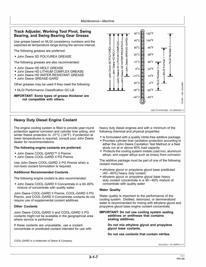
Maintenance—Machine
CED,TX14740,6952 -19-15DEC09-1/1
DX,COOL3 -19-14APR11-1/1
Track Adjuster, Working Tool Pivot, SwingBearing, and Swing Bearing Gear GreaseUse grease based on NLGI consistency numbers and theexpected air temperature range during the service interval.
The following greases are preferred:
• John Deere SD POLYUREA GREASE
The following greases are also recommended:
• John Deere HD MOLY GREASE• John Deere HD LITHIUM COMPLEX GREASE• John Deere HD WATER RESISTANT GREASE• John Deere GREASE-GARDOther greases may be used if they meet the following:
• NLGI Performance Classification GC-LBIMPORTANT: Some types of grease thickener are
not compatible with others.
TS1667
—UN—30JU
N99
Heavy Duty Diesel Engine Coolant
The engine cooling system is filled to provide year-roundprotection against corrosion and cylinder liner pitting, andwinter freeze protection to -37°C (-34°F). If protection atlower temperatures is required, consult your John Deeredealer for recommendations.
The following engine coolants are preferred:
• John Deere COOL-GARD™ II Premix• John Deere COOL-GARD II PG Premix
Use John Deere COOL-GARD II PG Premix when anon-toxic coolant formulation is required.
Additional Recommended Coolants
The following engine coolant is also recommended:
• John Deere COOL-GARD II Concentrate in a 40–60%mixture of concentrate with quality water.
John Deere COOL-GARD II Premix, COOL-GARD II PGPremix, and COOL-GARD II Concentrate coolants do notrequire use of supplemental coolant additives.
Other Coolants
John Deere COOL-GARD II and COOL-GARD II PGcoolants might not be available in the geographical areawhere service is performed.
If these coolants are unavailable, use a coolantconcentrate or prediluted coolant intended for use with
heavy duty diesel engines and with a minimum of thefollowing chemical and physical properties:
• Is formulated with a quality nitrite-free additive package.• Provides cylinder liner cavitation protection according toeither the John Deere Cavitation Test Method or a fleetstudy run at or above 60% load capacity• Protects the cooling system metals (cast iron, aluminumalloys, and copper alloys such as brass) from corrosion
The additive package must be part of one of the followingcoolant mixtures:
• ethylene glycol or propylene glycol base prediluted(40—60%) heavy duty coolant• ethylene glycol or propylene glycol base heavyduty coolant concentrate in a 40—60% mixture ofconcentrate with quality water
Water Quality
Water quality is important to the performance of thecooling system. Distilled, deionized, or demineralizedwater is recommended for mixing with ethylene glycol andpropylene glycol base engine coolant concentrate.
IMPORTANT: Do not use cooling system sealingadditives or antifreeze that containssealing additives.
Do not mix ethylene glycol and propyleneglycol base coolants.
Do not use coolants that contain nitrites.
COOL-GARD is a trademark of Deere & Company
3-1-7 013013
PN=58
Maintenance—Machine
DX,COOL11 -19-14APR11-1/1
DX,COOL16 -19-20APR11-1/1
Drain Intervals for Diesel Engine Coolant
Drain and flush the cooling system and refill with freshcoolant at the indicated interval, which varies with thecoolant used.
John Deere COOL-GARD™ II Premix, COOL-GARDII PG Premix and COOL-GARD II Concentrate aremaintenance free coolants for up to six years or 6000hours of operation, provided that the cooling system istopped off using only John Deere COOL-GARD II Premixor COOL-GARD II PG Premix.
Test the coolant condition annually with Coolant TestStrips designed for use with John Deere COOL-GARDII coolants. If the test strip chart indicates that additiveis required, add John Deere COOL-GARD II CoolantExtender as directed.
If John Deere COOL-GARD™ II Premix, COOL-GARD IIPG Premix, or COOL-GARD II Concentrate is used, butthe coolant is not tested OR additives are not replenishedby adding John Deere COOL-GARD II Coolant Extender,the drain interval is four years or 4000 hours of operation.This drain interval only applies to COOL-GARD II coolantsthat have been maintained within a 40—60% mixture ofconcentrate with quality water.
If a coolant other than COOL-GARD II, or COOL-GARDII PG is used, reduce the drain interval to two years or2000 hours of operation.
COOL-GARD is a trademark of Deere & Company
John Deere COOL-GARD™ II Coolant Extender
Some coolant additives will gradually deplete duringengine operation. For John Deere COOL-GARD™ IIPremix, COOL-GARD II PG Premix, and COOL-GARD IIConcentrate, replenish coolant additives between drainintervals by adding John Deere COOL-GARD II CoolantExtender.
John Deere COOL-GARD II Coolant Extender should notbe added unless indicated by coolant testing.
John Deere COOL-GARD II Coolant Extender is achemically matched additive system for use with allJohn Deere COOL-GARD II coolants. John DeereCOOL-GARD II Coolant Extender is not intended for usewith nitrite-containing coolants.
IMPORTANT: Do not add a supplemental coolantadditive when the cooling system is drainedand refilled with any of the following:
• John Deere COOL-GARD II• John Deere COOL-GARD II PG
The use of non-recommended supplemental coolantadditives may result in additive drop-out, gelation of thecoolant, or corrosion of cooling system components.
Add the recommended concentration of John DeereCOOL-GARD II Coolant Extender. DO NOT add morethan the recommended amount.
COOL-GARD is a trademark of Deere & Company
3-1-8 013013
PN=59

Maintenance—Machine
DX,COOL4 -19-14APR11-1/1
DX,COOL6 -19-03NOV08-1/1
Supplemental Coolant Additives
Some coolant additives will gradually deplete duringengine operation. For nitrite-containing coolants,replenish coolant additives between drain intervals byadding a supplemental coolant additive as determinednecessary by coolant testing.
John Deere Liquid Coolant Conditioner is recommendedas a supplemental coolant additive for nitrite-containingcoolants.
John Deere Liquid Coolant Conditioner is not designedfor use with John Deere COOL-GARD™ II Premix,COOL-GARD II PG Premix, or COOL-GARD IIConcentrate.
IMPORTANT: Do not add a supplemental coolantadditive when the cooling system is drainedand refilled with any of the following:
• John Deere COOL-GARD II• John Deere COOL-GARD II PG
If other coolants are used, consult the coolant supplierand follow the manufacturer's recommendation for use ofsupplemental coolant additives.
The use of non-recommended supplemental coolantadditives may result in additive drop-out and gelation ofthe coolant.
Add the manufacturer's recommended concentration ofsupplemental coolant additive. DO NOT add more thanthe recommended amount.
COOL-GARD is a trademark of Deere & Company
Operating in Warm Temperature Climates
John Deere engines are designed to operate using glycolbase engine coolants.
Always use a recommended glycol base engine coolant,even when operating in geographical areas where freezeprotection is not required.
John Deere COOL-GARD™ II Premix is available in aconcentration of 50% ethylene glycol. However, thereare situations in warm temperature climates where acoolant with lower glycol concentration (approximately20% ethylene glycol) has been approved. In these cases,the low glycol formulation has been modified to providethe same level of corrosion inhibitor as John DeereCOOL-GARD II Premix (50/50).
IMPORTANT: Water may be used as coolant inemergency situations only.
Foaming, hot surface aluminum and ironcorrosion, scaling, and cavitation will occurwhen water is used as the coolant, even whencoolant conditioners are added.
Drain cooling system and refill withrecommended glycol base engine coolantas soon as possible.
COOL-GARD is a trademark of Deere & Company
3-1-9 013013
PN=60
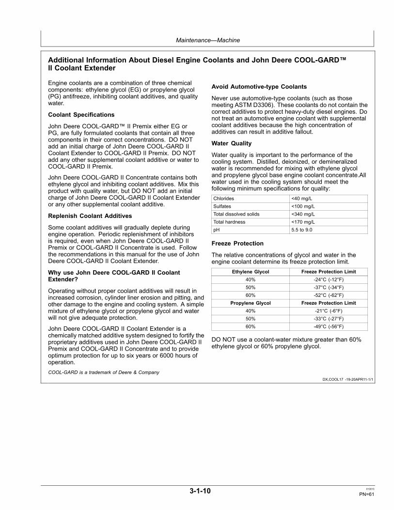
Maintenance—Machine
DX,COOL17 -19-20APR11-1/1
Additional Information About Diesel Engine Coolants and John Deere COOL-GARD™II Coolant Extender
Engine coolants are a combination of three chemicalcomponents: ethylene glycol (EG) or propylene glycol(PG) antifreeze, inhibiting coolant additives, and qualitywater.
Coolant Specifications
John Deere COOL-GARD™ II Premix either EG orPG, are fully formulated coolants that contain all threecomponents in their correct concentrations. DO NOTadd an initial charge of John Deere COOL-GARD IICoolant Extender to COOL-GARD II Premix. DO NOTadd any other supplemental coolant additive or water toCOOL-GARD II Premix.
John Deere COOL-GARD II Concentrate contains bothethylene glycol and inhibiting coolant additives. Mix thisproduct with quality water, but DO NOT add an initialcharge of John Deere COOL-GARD II Coolant Extenderor any other supplemental coolant additive.
Replenish Coolant Additives
Some coolant additives will gradually deplete duringengine operation. Periodic replenishment of inhibitorsis required, even when John Deere COOL-GARD IIPremix or COOL-GARD II Concentrate is used. Followthe recommendations in this manual for the use of JohnDeere COOL-GARD II Coolant Extender.
Why use John Deere COOL-GARD II CoolantExtender?
Operating without proper coolant additives will result inincreased corrosion, cylinder liner erosion and pitting, andother damage to the engine and cooling system. A simplemixture of ethylene glycol or propylene glycol and waterwill not give adequate protection.
John Deere COOL-GARD II Coolant Extender is achemically matched additive system designed to fortify theproprietary additives used in John Deere COOL-GARD IIPremix and COOL-GARD II Concentrate and to provideoptimum protection for up to six years or 6000 hours ofoperation.
Avoid Automotive-type Coolants
Never use automotive-type coolants (such as thosemeeting ASTM D3306). These coolants do not contain thecorrect additives to protect heavy-duty diesel engines. Donot treat an automotive engine coolant with supplementalcoolant additives because the high concentration ofadditives can result in additive fallout.
Water Quality
Water quality is important to the performance of thecooling system. Distilled, deionized, or demineralizedwater is recommended for mixing with ethylene glycoland propylene glycol base engine coolant concentrate.Allwater used in the cooling system should meet thefollowing minimum specifications for quality:Chlorides <40 mg/LSulfates <100 mg/LTotal dissolved solids <340 mg/LTotal hardness <170 mg/LpH 5.5 to 9.0
Freeze Protection
The relative concentrations of glycol and water in theengine coolant determine its freeze protection limit.
Ethylene Glycol Freeze Protection Limit40% -24°C (-12°F)50% -37°C (-34°F)60% -52°C (-62°F)
Propylene Glycol Freeze Protection Limit40% -21°C (-6°F)50% -33°C (-27°F)60% -49°C (-56°F)
DO NOT use a coolant-water mixture greater than 60%ethylene glycol or 60% propylene glycol.
COOL-GARD is a trademark of Deere & Company
3-1-10 013013
PN=61

Maintenance—Machine
DX,COOL9 -19-11APR11-1/1
Testing Diesel Engine Coolant
Maintaining adequate concentrations of glycol andinhibiting additives in the coolant is critical to protect theengine and cooling system against freezing, corrosion,and cylinder liner erosion and pitting.
Test the coolant solution at intervals of 12 months or lessand whenever excessive coolant is lost through leaks oroverheating.
Coolant Test Strips
Coolant test strips are available from your John Deeredealer. These test strips provide a simple, effectivemethod to check the freeze point and additive levels ofyour engine coolant.
When Using John Deere COOL-GARD II
John Deere COOL-GARD II Premix™ , COOL-GARDII PG Premix and COOL-GARD II Concentrate aremaintenance free coolants for up to six years or 6000hours of operation, provided that the cooling system istopped off using only John Deere COOL-GARD II Premixor COOL-GARD II PG premix. Test the coolant conditionannually with coolant test strips designed for use withJohn Deere COOL-GARD II coolants. If the test stripchart indicates that additive is required, add John DeereCOOL-GARD II Coolant Extender as directed.
Add only the recommended concentration of John DeereCOOL-GARD II Coolant Extender. DO NOT add morethan the recommended amount.
When Using Nitrite-Containing Coolants
Compare the test strip results to the supplemental coolantadditive (SCA) chart to determine the amount of inhibitingadditives in your coolant and whether more John DeereLiquid Coolant Conditioner should be added.
Add only the recommended concentration of John DeereLiquid Coolant Conditioner. DO NOT add more than therecommended amount.
Coolant Analysis
For a more thorough evaluation of your coolant, perform acoolant analysis. The coolant analysis can provide criticaldata such as freezing point, antifreeze level, pH, alkalinity,nitrite content (cavitation control additive), molybdatecontent (rust inhibitor additive), silicate content, corrosionmetals, and visual assessment.
Contact your John Deere dealer for more information oncoolant analysis.
COOL-GARD is a trademark of Deere & Company
3-1-11 013013
PN=62

Maintenance—Periodic Maintenance
TX14740,0001C9F -19-17JUL07-1/1
ER93822,00000FC -19-28FEB12-1/1
Service Machine at Specified IntervalsLubricate, make service checks, and make adjustments atintervals shown on the periodic maintenance chart and onthe following pages.
Perform service on items at multiples of the originalrequirement. For example, at 500 hours also servicethose items (if applicable) listed under 250 hours, 100hours, 50 hours, and 10 hours or daily.
Check the Hour Meter Regularly
T204968—UN—07DEC04
Hour Meter (S.N. —280538)
TX1109210—UN—27FE
B12
Hour Meter (S.N. 280539— )
1—Hour Meter
Check the hour meter (1) to determine when your machineneeds periodic maintenance.
Intervals on the periodic maintenance chart are foroperating in normal conditions. If you operate your
machine in difficult conditions, you should service it atshorter intervals.
3-2-1 013013
PN=63

Maintenance—Periodic Maintenance
ER93822,00001A0 -19-10JUN08-1/1
Prepare Machine for Maintenance1. Park machine on a level surface, and lower bucket
to the ground as shown.
2. Turn auto-idle switch to the OFF position.
3. Turn the engine speed dial (1) to slow idle.
4. Stop engine and remove key.
5. Pull the pilot shutoff lever (2) to the lock position.
1—Engine Speed Dial 2—Pilot Shutoff Lever
TX1043276—UN—06JU
N08
TX1043350A
—UN—04JU
N08
TX1043759A
—UN—10JU
N08
3-2-2 013013
PN=64
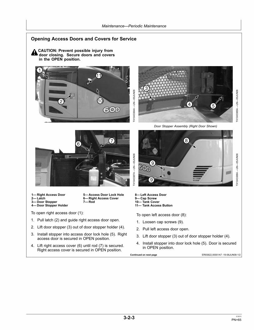
Maintenance—Periodic Maintenance
Continued on next page ER93822,00001A7 -19-06JUN08-1/2
Opening Access Doors and Covers for Service
CAUTION: Prevent possible injury fromdoor closing. Secure doors and coversin the OPEN position.
TX1043384A
—UN—05JU
N08
TX1043385A
—UN—05JU
N08
Door Stopper Assembly (Right Door Shown)
TX1043387A
—UN—05JU
N08
TX1043388A
—UN—05JU
N08
1—Right Access Door2—Latch3—Door Stopper4—Door Stopper Holder
5—Access Door Lock Hole6—Right Access Cover7—Rod
8—Left Access Door9—Cap Screw10— Tank Cover11— Tank Access Button
To open right access door (1):
1. Pull latch (2) and guide right access door open.
2. Lift door stopper (3) out of door stopper holder (4).
3. Install stopper into access door lock hole (5). Rightaccess door is secured in OPEN position.
4. Lift right access cover (6) until rod (7) is secured.Right access cover is secured in OPEN position.
To open left access door (8):
1. Loosen cap screws (9).
2. Pull left access door open.
3. Lift door stopper (3) out of door stopper holder (4).
4. Install stopper into door lock hole (5). Door is securedin OPEN position.
3-2-3 013013
PN=65

Maintenance—Periodic Maintenance
ER93822,00001A7 -19-06JUN08-2/2
TX1043389A
—UN—05JU
N08
TX1043390A
—UN—05JU
N08
TX1043391A
—UN—05JU
N08
10— Tank Cover11— Tank Access Button12— Wire
13— Cover Stopper14— Cover Stopper Holder15— Lock Hollow
16— Engine Access Door17— Engine Access Latch
18— Engine Access Stopper
To open tank cover (10):
1. Press tank access button (11).
2. Lift and guide tank cover toward the front of machineuntil wire (12) is extended.
3. Lift cover stopper (13) out of cover stopper holder (14).
4. Install stopper into lock hollow (15).
5. Lift cover gently until stopper is secured in lock hollow.Cover is secured in OPEN position.
To open engine access door (16):
1. Lift engine access latch (17) to open engine accessdoor.
2. Fully raise engine access door.
3. Engine access stopper (18) secures engine accessdoor in OPEN position.
To close engine access door, lift cover and push in tophalf of engine access stopper simultaneously to releaseengine access stopper. Slowly allow the engine accessdoor to begin lowering. Release pressure on engineaccess stopper. Complete closing of engine access doorby securely setting engine access latch.
3-2-4 013013
PN=66

Maintenance—Periodic Maintenance
MD04263,000007D -19-22OCT12-1/3
Continued on next page MD04263,000007D -19-22OCT12-2/3
Tilting the Operator StationIMPORTANT: Avoid machine damage. Do not use
another method of tilting the operator station.
Avoid damaging the tilt mechanism oroperator station. Raise and lower theoperator station slowly.
Tilting Operator Station
1. Park machine on level surface with pilot shutoff leverin the locked position.
2. Close cab door, if equipped.
3. Move boom as far to the right as possible and retractall cylinders to avoid damaging machine.
T205706A
—UN—06DEC04
Tilting Boom Position
4. Loosen panel cap screws (1) and raise panel (2).Tighten screws to hold panel in place.
IMPORTANT: Avoid damaging operator stationplatform. Do not remove operator stationplatform cap screws (3).
5. Remove four operator station mounting cap screws (4)from rear of operator station.
1—Panel Cap Screw (2 used)2—Panel
3—Operator Station PlatformCap Screw (2 used)
4—Operator Station MountingCap Screw (4 used)
T205611—UN—07DEC04
TX1124549—UN—23OCT12
3-2-5 013013
PN=67
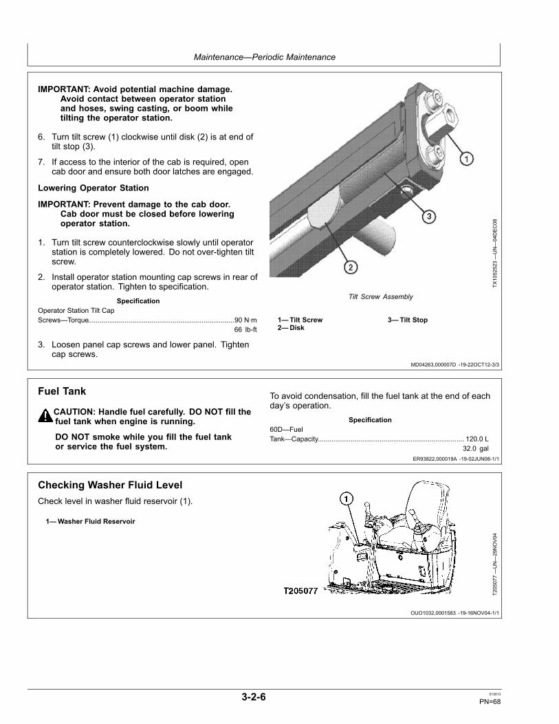
Maintenance—Periodic Maintenance
MD04263,000007D -19-22OCT12-3/3
ER93822,000019A -19-02JUN08-1/1
OUO1032,0001583 -19-16NOV04-1/1
IMPORTANT: Avoid potential machine damage.Avoid contact between operator stationand hoses, swing casting, or boom whiletilting the operator station.
6. Turn tilt screw (1) clockwise until disk (2) is at end oftilt stop (3).
7. If access to the interior of the cab is required, opencab door and ensure both door latches are engaged.
Lowering Operator Station
IMPORTANT: Prevent damage to the cab door.Cab door must be closed before loweringoperator station.
1. Turn tilt screw counterclockwise slowly until operatorstation is completely lowered. Do not over-tighten tiltscrew.
2. Install operator station mounting cap screws in rear ofoperator station. Tighten to specification.
SpecificationOperator Station Tilt CapScrews—Torque............................................................................90 N·m
66 lb-ft
3. Loosen panel cap screws and lower panel. Tightencap screws.
TX1052523—UN—04DEC08
Tilt Screw Assembly
1—Tilt Screw2—Disk
3—Tilt Stop
Fuel Tank
CAUTION: Handle fuel carefully. DO NOT fill thefuel tank when engine is running.
DO NOT smoke while you fill the fuel tankor service the fuel system.
To avoid condensation, fill the fuel tank at the end of eachday’s operation.
Specification60D—FuelTank—Capacity............................................................................ 120.0 L
32.0 gal
Checking Washer Fluid LevelCheck level in washer fluid reservoir (1).
1—Washer Fluid Reservoir
T205077—UN—29NOV04
3-2-6 013013
PN=68

Maintenance—Periodic Maintenance
VD76477,00000C8 -19-18APR06-1/1
TX,50,FF2898 -19-08NOV01-1/1
Hydraulic Breaker and Crusher AttachmentsIMPORTANT: Avoid mixing different brands or types
of oils. Oil manufacturers engineer their oils tomeet certain specifications and performancerequirements. Mixing different oil types candegrade lubricant and machine performance.
This excavator is factory filled with 46HNextended life zinc-free hydraulic oil. Avoidservicing this excavator with products that donot meet this specification. If oils have been
mixed or if alternate service oils are desired,the complete hydraulic system needs to betotally flushed by an authorized dealer.
Hydraulic breaker or crusher operation subjects themachine’s hydraulic system to possible contaminationand accelerated deterioration. The hydraulic returnfilter and hydraulic oil must be replaced more often toprevent damage to hydraulic pumps and other hydrauliccomponents. Use of different attachments may shorten oilchange interval. Use this table for reference.
Bucket, Breaker, and Crusher AttachmentsAttachment Percentage of Operating Time Hydraulic Return Filter
Change IntervalHydraulic Oil Change Interval
Bucket 100% 500 hours 2000 hoursBreaker or Crusher 100% 250 hours 1000 hours
Maintenance and Repair Record KeepingSystemThe checklist in this section summarizes scheduledmaintenance, and parts and oil required at eachmaintenance interval.
Use the checklist to:
• Remind you to perform machine maintenance atspecified intervals to minimize downtime.• Calculate cost of machine operation and ownershipallowing you to make better job estimates.• Place yourself in a stronger position at trade-in time.• Satisfy your SECURE contract requirements.
As maintenance is performed, check off each item on thelist and record date and hour meter reading.
Do not tear out or mark on checklist in this section; keep itto make extra copies.
T7511C
O—UN—27JU
N91
3-2-7 013013
PN=69

Maintenance—Periodic Maintenance
AM40430,00002FE -19-19OCT11-1/1
Fluid Analysis Program Test Kits and 3-WayCoolant Test KitFluid Analysis Program Test Kits and the 3-Way CoolantTest Kit are John Deere fluid sampling products to help youmonitor machine maintenance and system condition. Theobjective of a fluid sampling program is to ensure machineavailability when you need it and to reduce repair costs byidentifying potential problems before they become critical.
Engine, hydraulic, power train, and coolant samplesshould be taken from each system on a periodic basis,usually prior to a filter and/or fluid change interval. Certainsystems require more frequent sampling. Consult yourauthorized John Deere dealer on a maintenance programfor your specific application. Your authorized John Deeredealer has the sampling products and expertise to assistyou in lowering your overall operating costs through fluidsampling.
TX1003513A
—UN—20FE
B06
Fluid Analysis Kits
3-2-8 013013
PN=70

Maintenance—Periodic Maintenance
Continued on next page ER93822,00000FE -19-28FEB12-1/2
Service IntervalsService your machine at intervals shown on this chart. Also, perform service on items at multiples of the original requirement. For exam-ple, at 2000 hours also service those items (if applicable) listed under 1000 hours, 500 hours, 250 hours, 50 hours, and 10 hours or daily.OIL SAMPLINGOil samples should be taken from each system prior to its recommended drain/change interval indicated on this form: 250, 500, 1000, and 2000hours. Maintenance recommendations will be provided based upon the oil analysis and operating information you supply. Regular oil sampling willextend the operational life of your machine’s systems.
As Required□ Clean air cleaner element □ Clean radiator core□ Add coolant extender as indicated by COOL-GARD™ II test strips
Every 10 Hours or Daily□ Check engine oil level □ Check coolant level at recovery tank□ Check hydraulic tank oil level □ Check bucket teeth□ Drain fuel tank sump □ Check track sag□ Drain water separator □ Check seat belt
Initial Service—50 Hours1
□ Grease bucket and link pins □ Check and adjust fan belt tension□ Grease front joint pins1Perform initial service once after the first 50 hours of operation.
Every 100 Hours□ Grease bucket and link pins □ Check and adjust fan belt tension□ Grease front joint pins
Initial Service—250 Hours2
□ Replace hydraulic oil filter2Perform initial service once after the first 250 hours of operation.
Every 250 Hours□ Take engine oil sample □ Lubricate swing bearing□ Check travel gearbox oil level □ Drain hydraulic oil tank sump□ Lubricate device tilting mechanism □ Lubricate angle blade bottom pin—if equipped□ Lubricate angle blade rod pin—if equipped
Every 500 Hours□ Take engine coolant sample □ Take travel gearbox oil sample□ Take diesel fuel sample □ Take hydraulic oil sample□ Replace air cleaner element □ Replace hydraulic oil filter□ Lubricate front joint pins □ Replace fuel filter□ Lubricate swing bearing gear □ Change engine oil and replace filter□ Lubricate control lever universal joint □ Lubricate blade pins□ Lubricate center pin—if equipped
Every 1000 Hours□ Drain and refill travel gearbox oil □ Check and adjust valve clearance□ Replace pilot control oil filter □ Check starter and alternator□ Inspect crankcase breather system □ Check coolant
Every 2000 Hours□ Drain and refill hydraulic tank oil, clean suction screen
Every 6000 Hours
3-2-9 013013
PN=71

Maintenance—Periodic Maintenance
ER93822,00000FE -19-28FEB12-2/2
ER93822,00000FD -19-28FEB12-1/1
Service your machine at intervals shown on this chart. Also, perform service on items at multiples of the original requirement. For exam-ple, at 2000 hours also service those items (if applicable) listed under 1000 hours, 500 hours, 250 hours, 50 hours, and 10 hours or daily.□ Drain and refill engine coolant
COOL-GARD is a trademark of Deere & Company
Required PartsREQUIRED PARTS
Ensure machine performance and availability; use only genuine John Deere parts. Verify part numbers are current and that anyassociated parts are also on hand, i.e., filter O-rings.
Item PartNumber
InitialService—250
Hours1
Every 250Hours
Every 500Hours
Every 1000Hours
Every 2000Hours
Every 6000Hours
Hydraulic System Return Oil Filter AT308568 1 1 1 1 1O-Ring for AT308568 4621929 1 1 1 1 1Engine Oil Filter MIU800650 1 1 1 1Fuel Filter Element MIU801090 1 1 1 1Air Filter Primary RE68048 1 1 1 1Pilot Control Oil Filter 4294130 1 1 1O-Ring for 4294130 4294161 1 1 1Engine Rocker Arm Cover Gasket MIU801150 1 1 1Fuel and Water Separator Element MIU801025 As NeededCab Air Recirculation Filter 4684045 As NeededCab Fresh Air Filter 4673287 As NeededJohn Deere Plus-50™ II Oil TY266732 11.2 L
(3.0 gal.)11.2 L
(3.0 gal.)11.2 L
(3.0 gal.)11.2 L
(3.0 gal.)API GL-5 Gear Oil (each travelgearbox)
TY62962 0.9 L(1.0 qt.)
0.9 L(1.0 qt.)
0.9 L(1.0 qt.)
Hitachi SUPER EX 46HN HydraulicOil
2908-0502 87 L(23.0 gal.)
87 L(23.0 gal.)
COOL-GARD™ II Pre-mix TY26575 6.5 L(2.0 gal.)
Coolant Extender TY26603 As NeededFluid Analysis Kits3
• Diesel Engine Oil AT346594 1 1 1 1 1• Hydraulic Oil AT346594 1 1 1 1• Travel Gearbox Oil AT346594 2 2 2 2• Diesel Fuel AT180344 1 1 1 1• Engine Coolant TY26873 1 1 1 1COOL-GARD™II Test Strips TY26605 1 1 1
1Perform initial service once after the first 250 hours ofoperation.2For recommended oil types and oil viscosities basedon operating temperatures, see Maintenance-Machine.(Section 3-1.)
3Based on fluid analysis results, intervals may need tobe adjusted for your operating conditions. Consult yourlocal John Deere dealer,
Plus-50 is a trademark of Deere & CompanyCOOL-GARD is a trademark of Deere & Company
3-2-10 013013
PN=72

Maintenance—As Required
ER93822,0000193 -19-05JUN08-1/1
OUO1032,000159E -19-17NOV04-1/1
Cleaning Air Cleaner Element1. Loosen clamps (2) to remove cover (3).
2. Remove element (1).
3. Tap element with the palm of your hand, NOT ON AHARD SURFACE.
CAUTION: Prevent possible injury from flyingchips if compressed air is more than 210 kPa(2.1 bar) (30 psi). Reduce compressed air to lessthan 210 kPa (2.1 bar) (30 psi) when using forcleaning purposes. Clear area of bystanders,guard against flying chips, and wear personalprotection equipment including eye protection.
4. If this does not remove dust, use compressed airunder 210 kPa (2.1 bar) (30 psi).
5. Direct air up and down from inside to outside. Becareful not to make a break in the element.
6. Install element.
7. Install cover with dust unloader valve (4) pointingdown and tighten clamps.
8. Check air filter restriction indicator (5). If necessary,replace element. See Replacing Air Cleaner Element.(Section 3-7.)
T123610—UN—17AUG99
TX1043392A
—UN—05JU
N08
1—Air Cleaner Element2—Clamp (2 used)3—Cover
4—Dust Unloader Valve5—Air Filter Restriction
Indicator
Cleaning Radiator Core and Oil Cooler
CAUTION: Prevent possible injury from flyingchips if compressed air is more than 210 kPa(2.1 bar) (30 psi). Reduce compressed air to lessthan 210 kPa (2.1 bar) (30 psi) when using forcleaning purposes. Clear area of bystanders,
guard against flying chips, and wear personalprotection equipment including eye protection.
Clean the radiator core and oil cooler with compressed airor water. Blow air straight through fins to avoid bendingthem.
3-3-1 013013
PN=73

Maintenance—As Required
ER93822,0000102 -19-27FEB12-1/1
Check Coolant
CAUTION: Explosive release of fluids frompressurized cooling system can causeserious burns.
Remove radiator filler cap (1) only when engineis cold or when cool enough to touch with barehands. Slowly loosen cap to relieve pressurebefore removing completely.
IMPORTANT: John Deere COOL-GARD™ IICoolant Extender does not protect againstfreezing. Coolant extender prevents rust,scale, and liner cavitation.
NOTE: Check coolant every 1000 hours or 1 year,or when replacing 1/3 or more of coolant. Addcoolant extender as indicated by John DeereCOOL-GARD™ II test strips.
1. Remove radiator filler cap (1) and test coolant solution.Use the following kit to check coolant:
• COOL-GARD™ II Test StripsCoolant test strips provide an effective methodto check freeze point and additive levels ofengine coolant. See your authorized dealer forCOOL-GARD™ II test strips and follow instructionson kit.
2. Add John Deere COOL-GARD™ II Coolant Extenderas necessary. Follow instructions on container foramount. For more information concerning coolingsystem capacity, see Drain and Refill Capacities.(Section 4-6.)
TS281—UN—23AUG88
T205085—UN—01DEC04
Recovery Tank
1—Radiator Filler Cap 2—Recovery Tank
3. Install radiator filler cap.
COOL-GARD is a trademark of Deere & Company
3-3-2 013013
PN=74
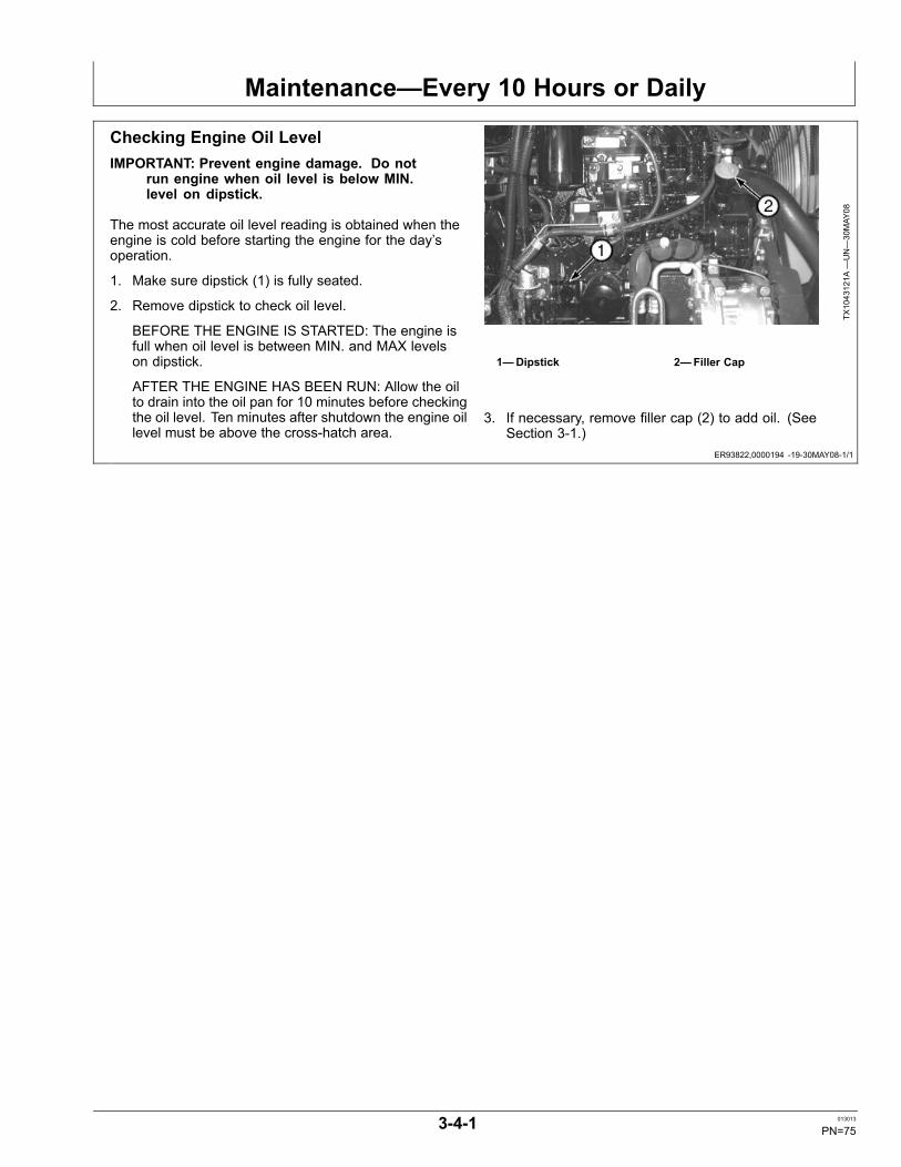
Maintenance—Every 10 Hours or Daily
ER93822,0000194 -19-30MAY08-1/1
Checking Engine Oil LevelIMPORTANT: Prevent engine damage. Do not
run engine when oil level is below MIN.level on dipstick.
The most accurate oil level reading is obtained when theengine is cold before starting the engine for the day’soperation.
1. Make sure dipstick (1) is fully seated.
2. Remove dipstick to check oil level.
BEFORE THE ENGINE IS STARTED: The engine isfull when oil level is between MIN. and MAX levelson dipstick.
AFTER THE ENGINE HAS BEEN RUN: Allow the oilto drain into the oil pan for 10 minutes before checkingthe oil level. Ten minutes after shutdown the engine oillevel must be above the cross-hatch area.
TX1043121A
—UN—30MAY
08
1—Dipstick 2—Filler Cap
3. If necessary, remove filler cap (2) to add oil. (SeeSection 3-1.)
3-4-1 013013
PN=75
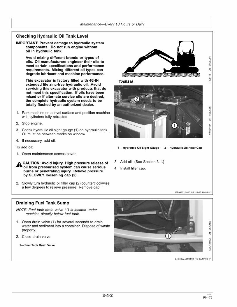
Maintenance—Every 10 Hours or Daily
ER93822,0000195 -19-05JUN08-1/1
ER93822,00001A9 -19-05JUN08-1/1
Checking Hydraulic Oil Tank LevelIMPORTANT: Prevent damage to hydraulic system
components. Do not run engine withoutoil in hydraulic tank.
Avoid mixing different brands or types ofoils. Oil manufacturers engineer their oils tomeet certain specifications and performancerequirements. Mixing different oil types candegrade lubricant and machine performance.
This excavator is factory filled with 46HNextended life zinc-free hydraulic oil. Avoidservicing this excavator with products that donot meet this specification. If oils have beenmixed or if alternate service oils are desired,the complete hydraulic system needs to betotally flushed by an authorized dealer.
1. Park machine on a level surface and position machinewith cylinders fully retracted.
2. Stop engine.
3. Check hydraulic oil sight gauge (1) on hydraulic tank.Oil must be between marks on window.
4. If necessary, add oil.
To add oil:
1. Open maintenance access cover.
CAUTION: Avoid injury. High pressure release ofoil from pressurized system can cause seriousburns or penetrating injury. Relieve pressureby SLOWLY loosening cap (2).
2. Slowly turn hydraulic oil filler cap (2) counterclockwisea few degrees to relieve pressure. Remove cap.
T205418—UN—09DEC04
TX1043418A
—UN—05JU
N08
1—Hydraulic Oil Sight Gauge 2—Hydraulic Oil Filler Cap
3. Add oil. (See Section 3-1.)
4. Install filler cap.
Draining Fuel Tank SumpNOTE: Fuel tank drain valve (1) is located under
machine directly below fuel tank.
1. Open drain valve (1) for several seconds to drainwater and sediment into a container. Dispose of wasteproperly.
2. Close drain valve.
1—Fuel Tank Drain Valve
TX1043419A
—UN—05JU
N08
3-4-2 013013
PN=76

Maintenance—Every 10 Hours or Daily
ER93822,00001AA -19-05JUN08-1/1
ER93822,00001AB -19-05JUN08-1/1
CED,TX14740,6421 -19-03JUL02-1/1
Draining Water Separator1. Open right access door to access water separator (1).
2. Open drain valve (2) for several seconds to drainwater and sediment into a container. Dispose of wasteproperly.
3. Close drain valve.
4. Close access door.
1—Water Separator 2—Drain Valve
TX1043424A
—UN—05JU
N08
Checking Recovery Tank Coolant LevelWith the engine cold, coolant level must be between theFULL and LOW marks on the recovery tank (2).
If coolant is below the LOW mark, add coolant to therecovery tank.
CAUTION: Prevent possible injury from hotspraying water. DO NOT remove radiatorfiller cap (1) unless engine is cool. Then turncap slowly to the stop. Release all pressurebefore you remove cap.
IMPORTANT: Avoid mixing different brands or typesof coolant. Coolant manufacturers engineertheir coolants to meet certain specificationsand performance requirements. Mixingdifferent coolant types can degrade coolantand machine performance.
If recovery tank is empty, check for leaks. Repair asrequired. Add coolant to the radiator then the recoverytank.
T205085—UN—01DEC04
Recovery Tank
1—Radiator Filler Cap 2—Recovery Tank
NOTE: If recovery tank is full and radiator is low, checkfor leaks in radiator cap and hose connectionsbetween radiator and coolant recovery tank.
Coolant level must be at bottom of the radiator filler neck.
Checking Bucket TeethCheck bucket teeth for wear. Replace tooth if tooth wearis below 65 mm (2.6 in.)
CAUTION: Guard against injury from flying piecesof metal; wear goggles or safety glasses.
NOTE: Alternate buckets may use different toothassemblies.
3-4-3 013013
PN=77

Maintenance—Every 10 Hours or Daily
OUO1032,00015B4 -19-25JAN07-1/2
OUO1032,00015B4 -19-25JAN07-2/2
Checking Track Sag—Rubber Track1. Rotate upperstructure so front of upperstructure is
over travel motors (180°).
2. Lower the bucket and blade to raise both tracks offground.
3. Raise pilot control shutoff lever to locked position.
CAUTION: Prevent possible injury fromunexpected machine movement. Place blocksunder machine frame to support machinewhile measuring track sag.
4. Place blocks under machine frame to support machine.
5. Lower pilot control shutoff lever to unlocked position.
6. Rotate track so track joint is positioned at the uppercenter of the track.
T121880—UN—18JU
N99
7. Stop engine.
8. Measure distance (1) from bottom of center roller toinner ridge of rubber track.
SpecificationTrack—Sag.............................................................................10—15 mm
0.4—0.6 in.
9. If not to specification, adjust track sag. See AdjustingTrack Sag.
10. Repeat check on other side of machine.
1—Track Sag Distance
T121709—UN—10JU
N99
T121710—UN—10JU
N99
3-4-4 013013
PN=78
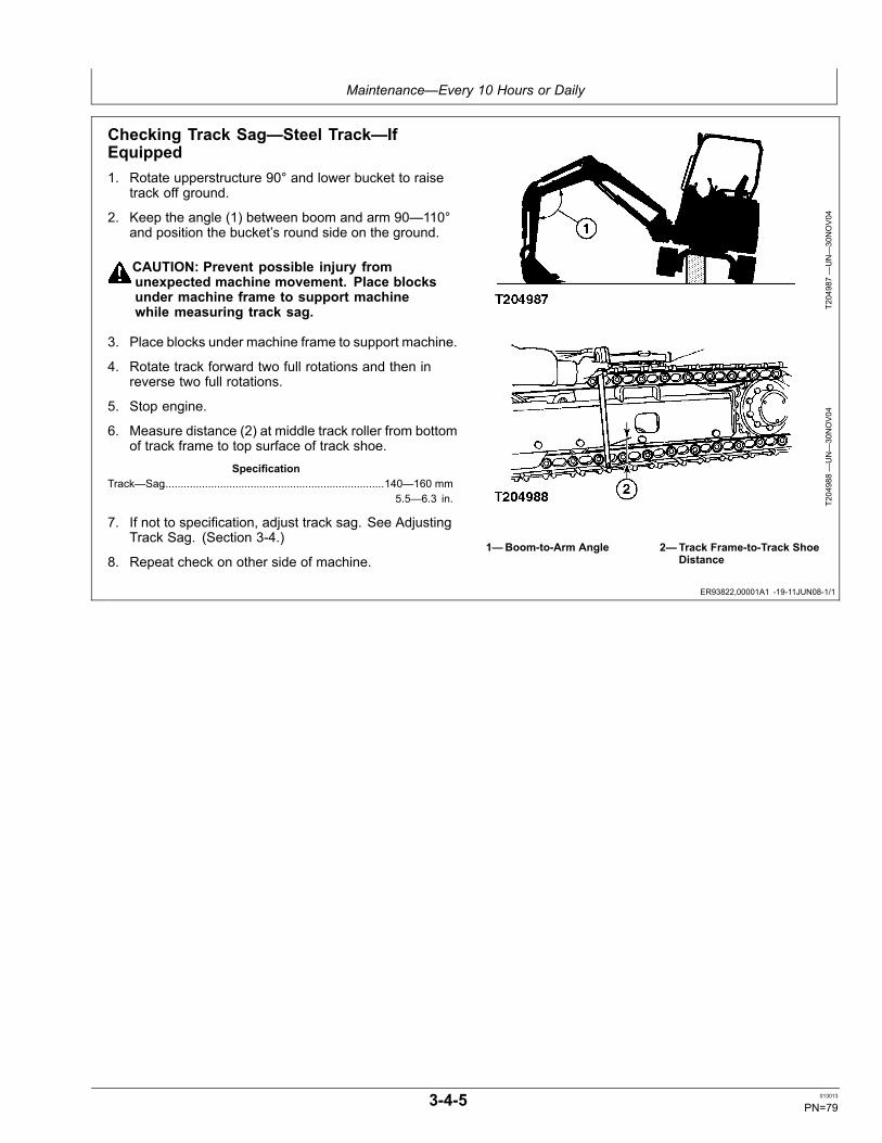
Maintenance—Every 10 Hours or Daily
ER93822,00001A1 -19-11JUN08-1/1
Checking Track Sag—Steel Track—IfEquipped1. Rotate upperstructure 90° and lower bucket to raise
track off ground.
2. Keep the angle (1) between boom and arm 90—110°and position the bucket’s round side on the ground.
CAUTION: Prevent possible injury fromunexpected machine movement. Place blocksunder machine frame to support machinewhile measuring track sag.
3. Place blocks under machine frame to support machine.
4. Rotate track forward two full rotations and then inreverse two full rotations.
5. Stop engine.
6. Measure distance (2) at middle track roller from bottomof track frame to top surface of track shoe.
SpecificationTrack—Sag.........................................................................140—160 mm
5.5—6.3 in.
7. If not to specification, adjust track sag. See AdjustingTrack Sag. (Section 3-4.)
8. Repeat check on other side of machine.
T204987—UN—30NOV04
T204988—UN—30NOV04
1—Boom-to-Arm Angle 2—Track Frame-to-Track ShoeDistance
3-4-5 013013
PN=79

Maintenance—Every 10 Hours or Daily
OUO1032,000158B -19-18JUL06-1/1
TX03679,00016DD -19-03NOV08-1/1
Adjusting Track SagIMPORTANT: Prevent possible damage to track
components. DO NOT use the grease fitting onthe track adjusting cylinder for lubrication. Usethis fitting ONLY for track adjustment.
To tighten track, connect a grease gun to grease fitting(1) (located through access hole [4] in track frame). Addgrease until sag is within recommended limits.
CAUTION: Prevent possible serious injury fromhigh-pressure grease penetrating your skin.Do not remove grease fitting (1) from valve (2).If grease does not escape immediately fromthe vent hole when check valve is loosened,slowly drive machine in forward and reversedirection until grease escapes. DO NOTdisassemble parts until you know the correctprocedure and have the correct tools. Seeyour authorized John Deere dealer.
If an accident occurs, see a doctor immediately.Any oil injected into the skin must be surgicallyremoved within a few hours or gangrenemay result. Doctors unfamiliar with thistype of injury may call Deere & CompanyMedical Department in Moline, Illinois, or otherknowledgeable medical source.
To loosen, slowly turn valve (2) counterclockwise; greasewill escape through the bleed hole (3).
When amount of track sag is satisfactory, turn valveclockwise to tighten.
T204989—UN—30NOV04
T121713—UN—10JU
N99
Steel Track Shown
1—Grease Fitting2—Valve
3—Bleed Hole4—Access Hole
Use and Maintain Seat BeltUse seat belt when operating machine. Remember tofasten seat belt when loading and unloading from trucksand during other uses.
Examine seat belt frequently. Be sure webbing is notcut or torn. Replace seat belt immediately if any part isdamaged or does not function properly.
The complete seat belt assembly should be replacedevery 3 years, regardless of appearance.
T133716—19—14SEP00
3-4-6 013013
PN=80

Maintenance—Initial Service—50 Hours
ER93822,0000104 -19-28FEB12-1/1
Lubricate Bucket and Link Pins
Lubricate bucket and link pins until grease escapes fromjoints. (See Section 3-1.) Lubricate every 10 hours whenworking in mud and water.
T205831—UN—07DEC04
Right Side Shown - 10 Points
3-5-1 013013
PN=81

Maintenance—Initial Service—50 Hours
Continued on next page ER93822,0000105 -19-28FEB12-1/2
Lubricate Front Joint Pins
T205002—UN—30NOV04
One Point
T205003—UN—30NOV04
One Point
T205004—UN—30NOV04
One Point
T205006—UN—30NOV04
Two Points
T205007—UN—30NOV04
Two Points
T205008—UN—30NOV04
One Point
T205009—UN—30NOV04
One Point
3-5-2 013013
PN=82

Maintenance—Initial Service—50 Hours
ER93822,0000105 -19-28FEB12-2/2
ER93822,0000106 -19-28FEB12-1/1
Add grease until grease escapes from joints. Lubricateevery 10 hours when working in mud and water. SeeGrease. (Section 3-1.)
Check and Adjust Fan Belt Tension1. Check belts regularly for wear. Replace if necessary.
2. Check fan belt tension with belt deflection gauge atmidway between fan pulley (5) and alternator (6).
Fan Belt—SpecificationDeflection—Deflection..............................................................8—10 mm
0.32—0.39 in.DepressingForce—Force....................................................................................98 N
22 lb (force)
3. If deflection is not within specifications, loosen capscrews (7—9).
4. Move alternator until tension is correct.
5. Tighten cap screws.
1—Compressor Pulley2—Tension Pulley3—Crank Pulley4—Bolt5—Fan Pulley
6—Alternator7—Cap Screw8—Alternator Bracket Cap
Screw9—Adjusting Plate Cap Screw
TX1037256—UN—27FE
B08
TX1037257—UN—26FE
B08
3-5-3 013013
PN=83

Maintenance—Every 100 Hours
CED,TX14740,6379 -19-28FEB12-1/1
Lubricate Bucket and Link Pins
Lubricate bucket and link pins until grease escapes fromjoints. (See Section 3-1.) Lubricate every 10 hours whenworking in mud and water.
T205831—UN—07DEC04
Right Side Shown - 10 Points
3-6-1 013013
PN=84

Maintenance—Every 100 Hours
Continued on next page ER93822,000019B -19-28FEB12-1/2
Lubricate Front Joint Pins
T205002—UN—30NOV04
One Point
T205003—UN—30NOV04
One Point
T205004—UN—30NOV04
One Point
T205006—UN—30NOV04
Two Points
T205007—UN—30NOV04
Two Points
T205008—UN—30NOV04
One Point
T205009—UN—30NOV04
One Point
3-6-2 013013
PN=85

Maintenance—Every 100 Hours
ER93822,000019B -19-28FEB12-2/2
ER93822,00001BC -19-28FEB12-1/1
Add grease until grease escapes from joints. Lubricateevery 10 hours when working in mud and water. SeeGrease. (Section 3-1.)
Check and Adjust Fan Belt Tension1. Check belts regularly for wear. Replace if necessary.
2. Check fan belt tension with belt deflection gauge atmidway between fan pulley (5) and alternator (6).
Fan Belt—SpecificationDeflection—Deflection..............................................................8—10 mm
0.32—0.39 in.DepressingForce—Force....................................................................................98 N
22 lb (force)
3. If deflection is not within specifications, loosen capscrews (7—9).
4. Move alternator until tension is correct.
5. Tighten cap screws.
1—Compressor Pulley2—Tension Pulley3—Crank Pulley4—Bolt5—Fan Pulley
6—Alternator7—Cap Screw8—Alternator Bracket Cap
Screw9—Adjusting Plate Cap Screw
TX1037256—UN—27FE
B08
TX1037257—UN—26FE
B08
3-6-3 013013
PN=86

Maintenance—Initial Service—250 Hours
ER93822,000010B -19-27FEB12-1/1
Replacing Hydraulic Oil Tank FilterNOTE: Perform this service at the first 250 hours of
operation and then at 500 hour intervals thereafter.
1. Park machine on a level surface with cylinders fullyretracted.
2. Stop engine.
CAUTION: High pressure release of oil frompressurized system can cause seriousburns or penetrating injury. The hydraulictank is pressurized. Slowly loosen capto release pressure.
3. Slowly loosen hydraulic oil tank cap to releasehydraulic pressure. Remove cap.
4. Hold down filter cover (2) against light spring loadwhen removing cap screws (1).
5. Remove spring (4), valve (5) and filter element (6).
NOTE: Remove element and inspect for metal particlesand debris in bottom of filter can. Excessiveamounts of brass and steel particles can indicatea hydraulic pump, motor, or valve malfunction, ora malfunction in process. Rubber-type materialcan indicate a cylinder packing problem.
6. Discard element and O-ring.
7. Fill new filter with oil. (See Section 3-1.)
8. Install new filter element, valve and spring.
9. Install cover and new O-ring.
10. Install cap screws.Specification
Cap Screw—Torque......................................................................49 N·m36 lb-ft
IMPORTANT: Avoid hydraulic pump damage.Hydraulic system must be bled whenever thehydraulic oil filter is changed.
11. Bleed hydraulic system. See Bleeding HydraulicSystem. (Section 4-1.)
T205418—UN—09DEC04
T205001—UN—30NOV04
1—Cap Screw (4 used)2—Cover3—O-Ring
4—Spring5—Valve6—Filter Element
3-7-1 013013
PN=87

Maintenance—Every 250 Hours
OUO1032,0001590 -19-28FEB12-1/1
ER93822,00001AE -19-28FEB12-1/1
Lubricate Swing Bearing
CAUTION: Prevent possible injury fromunexpected machine movement if controls aremoved by another person. Lubricating swingbearing gear and rotating the upperstructuremust be done by one person.
Each time you leave the cab:
• Lower the bucket to the ground• Stop the engine• Raise the pilot control shutoff lever tothe locked position.
1. Park machine on a level surface.
2. Turn key switch to OFF. Remove key from switch.
3. Lubricate swing bearing with 2—3 shots of grease atgrease fitting. (See Section 3-1.)
4. Start engine. Raise bucket several inches off theground and rotate upperstructure 90 degrees (1/4 turn).
T204996—UN—30NOV04
5. Repeat steps 2—4 seven times. It is not necessary tostart the engine the last time.
NOTE: Lubricate the swing bearing gear at 500 hours.
Lubricate Tilt Mechanism1. Park machine on a level surface.
2. Turn key switch to OFF. Remove key from switch.
3. Remove cap screws (1) from the tilt mechanism cover(2).
4. Remove tilt mechanism cover.
5. Coat entire length of bolt (3) with grease. See Grease.(Section 3-1.)
1—Cap Screw (2 used)2—Tilt Mechanism Cover
3—Bolt
TX1043430A
—UN—06JU
N08
TX1043431A
—UN—06JU
N08
3-8-1 013013
PN=88

Maintenance—Every 250 Hours
ER93822,000010D -19-28FEB12-1/1
CED,TX14740,6726 -19-13JUL11-1/1
Lubricate Angle Blade Bottom and RodPins—If EquippedAdd grease until grease escapes from joints. See Grease.(Section 3-1.)
TX1109315—UN—28FE
B12
Rod Pin
TX1109316—UN—28FE
B12
Bottom Pin
Checking Travel Gear Case Oil Level1. Park the machine on level ground rotating travel gear
case until positioned as shown.
2. Lower bucket and blade to the ground.
3. Run engine at slow idle speed without load for 5minutes.
4. Turn key switch to OFF. Remove key from switch.
5. Pull pilot control shutoff lever to locked position.
CAUTION: High pressure release of oils frompressurized system can cause serious burns.Wait for travel gear case oil to cool. Keep bodyand face away from check plug. Gradually loosencheck plug to release air to relieve pressure.
6. After travel gear case has cooled, slowly loosen fillplug (1) to release air to relieve pressure.
7. Remove check plug (2). Oil must be to bottom of hole.
8. If necessary, add oil until oil flows out of oil level checkplug hole. (See Section 3-1.)
T121259—UN—22APR99
1—Fill Plug 2—Check Plug
9. Install plugs.
10. Check second travel gear case oil level.
3-8-2 013013
PN=89

Maintenance—Every 250 Hours
ER93822,00001AC -19-12JUN08-1/1
OUT4001,000039B -19-14MAR12-1/1
Draining Hydraulic Oil Tank Sump
CAUTION: High-pressure release of oil frompressurized system can cause seriousburns or penetrating injury. The hydraulictank is pressurized. Slowly loosen capto release pressure.
1. Slowly loosen hydraulic oil filler cap to releasepressure.
2. Loosen hydraulic sump drain plug (1) for severalseconds to drain water and sediment into a container.Do not remove plug completely. Dispose of wasteproperly.
3. Tighten drain plug.
TX1043429A
—UN—05JU
N08
1—Hydraulic Sump Drain Plug
Take Engine Oil SampleSee your authorized dealer.
3-8-3 013013
PN=90

Maintenance—Every 500 Hours
ER93822,00001AF -19-28FEB12-1/1
Changing Engine Oil and Replacing Filter1. Run engine to warm oil.
2. Park machine on a level surface and stop engine.
3. Remove drain plug (1) from engine oil pan. Allow oil todrain into a container. Dispose of waste oil properly.
4. Turn engine oil filter (2) counterclockwise to remove.Clean mounting surface on base.
5. Apply thin film of oil to rubber gasket of new filter.
6. Install new filter. Turn filter clockwise by hand untilgasket touches mounting surface.
7. Tighten filter 1-1/4 turn more.
8. Install drain plug.
9. Remove engine oil filler cap (3).Specification
Oil Capacity with FilterChange—Capacity......................................................................... 11.2 L
3.0 gal
10. Fill engine with oil. (See Section 3-1.)
11. Install engine oil filler cap.
12. Start engine. Engine oil pressure indicator onmonitor must go out immediately. If not, stop engineimmediately and find the cause.
13. Stop engine. Check oil level on dipstick.
14. Check for any leakage at filter. Tighten filter justenough to stop leakage.
TX1043434A
—UN—06JU
N08
Oil Pan
TX1043435A
—UN—06JU
N08
Oil Filter and Filler Cap
1—Drain Plug2—Engine Oil Filter
3—Engine Oil Filler Cap
3-9-1 013013
PN=91
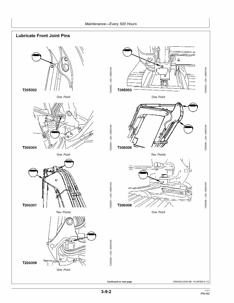
Maintenance—Every 500 Hours
Continued on next page ER93822,000019B -19-28FEB12-1/2
Lubricate Front Joint Pins
T205002—UN—30NOV04
One Point
T205003—UN—30NOV04
One Point
T205004—UN—30NOV04
One Point
T205006—UN—30NOV04
Two Points
T205007—UN—30NOV04
Two Points
T205008—UN—30NOV04
One Point
T205009—UN—30NOV04
One Point
3-9-2 013013
PN=92

Maintenance—Every 500 Hours
ER93822,000019B -19-28FEB12-2/2
OUO1032,0001593 -19-28FEB12-1/1
OUO1032,0001594 -19-28FEB12-1/1
Add grease until grease escapes from joints. Lubricateevery 10 hours when working in mud and water. SeeGrease. (Section 3-1.)
Lubricate Swing Bearing Gear
CAUTION: Prevent possible injury fromunexpected machine movement if controls aremoved by another person. Lubricating swingbearing gear and rotating the upperstructuremust be done by one person.
Each time you leave the cab:
• Lower the bucket to the ground• Stop the engine• Pull the pilot control shutoff lever tothe locked position.
1. Apply grease to grease fitting.
IMPORTANT: If water or mud is found in swinggear area, see Operating in Water andMud. (Section 2-2.)
T205010—UN—30NOV04
2. In order to apply grease evenly to the swing gear,raise the bucket approximately 200 mm (8 in.) off theground, swing upperstructure four 90° intervals andapply grease at each interval. Add grease as required.(See Section 3-1.)
Lubricate Control Lever Universal Joint1. Lift boot (1). Remove screws (2).
2. Remove bracket (3).
3. Lubricate points shown.
4. Install bracket and screws.
5. Install boot.
1—Boot2—Screw (2 used)
3—Bracket
T205011—UN—30NOV04
T205012—UN—30NOV04
Four Points
3-9-3 013013
PN=93

Maintenance—Every 500 Hours
ER93822,00001B0 -19-06JUN08-1/1
OUO1032,0001596 -19-28FEB12-1/1
ER93822,000010E -19-28FEB12-1/1
Replacing Final Fuel Filter1. Turn fuel shutoff valve (1) to OFF.
2. Remove fuel filter (2). Dispose of waste properly.
3. Clean mounting surface for fuel filter.
4. Add a small amount of fuel to new filter and install.
5. Turn fuel shutoff valve to ON.
6. Turn the key switch to ON for 10—15 seconds toengage automatic bleeding. Do not start engine.
7. Start engine. Stop engine. Check for fuel leakage.
TX1043437A
—UN—06JU
N08
TX1043438A
—UN—06JU
N08
Lubricate Blade PinsLubricate blade pins until grease escapes from joint. SeeGrease. (Section 3-1.)
T205163—UN—09DEC04
Four Points
Lubricate Center Pin—If EquippedLubricate pin until grease escapes from joint. See Grease.(Section 3-1.)
TX1109314—UN—28FE
B12
Center Pin
3-9-4 013013
PN=94

Maintenance—Every 500 Hours
Continued on next page ER93822,00001B1 -19-06JUN08-1/2
Replace Air Cleaner Elements and Dust Valve1. Shut off engine.
2. Open left access door.
3. Unlatch air cleaner cover (1) and remove.
4. Pull primary element (2) straight down to remove. Theprimary element makes a tight seal; there may be initialresistance when trying to remove it. To loosen fromhousing, grab the end of element and gently moveelement back and forth, and pull it out of housing.
IMPORTANT: Failure to clean the housing properlymay cause contaminants to be introducedto the seal area of the primary elementduring installation. This can cause a leakand shorter element life.
5. Clean the inside of filter canister. Use a soft rag toremove all dust and debris from the inside surface ofhousing. Be careful not to introduce contaminant intothe outlet tube.
NOTE: If the secondary element is not installedproperly, it may attach itself to the primaryelement upon removal.
6. Pull secondary element (if equipped) straight back toremove.
7. Before installing a new primary or secondary (ifequipped) filter, inspect it carefully. Visually checkfor any voids, cuts, tears, or indentations in theurethane-sealing surface. If the check revealsdamage, do NOT install the filter.
8. Install new secondary element (if equipped). Check toensure secondary element is properly seated in thehousing. It should fit snugly inside the outlet tube.Continue pushing filter into outlet tube until it stops.
9. Install new primary element. Apply pressure by handat the outer rim of element, not the center, to seatelement in housing. Sealing area will compressslightly and distribute the sealing pressure evenly.
TX1043442A
—UN—06JU
N08
TX1043440A
—UN—06JU
N08
1—Air Cleaner Cover 2—Primary Element
NOTE: Do not use service cover latches to force thecover in position. Cover latches will prematurelyfail if used to seat the cover.
10. Install air cleaner cover and fasten latches. The coverfor the air cleaner fits only one way. When in theproper position, it will fit snugly against the housing.The cover should go on easily with no extra force.
If cover does not seem to fit, filter is not properlyseated in the housing.
3-9-5 013013
PN=95

Maintenance—Every 500 Hours
ER93822,00001B1 -19-06JUN08-2/2
CS58540,000005C -19-13JUL11-1/1
NOTE: A missing, damaged, or hardened dust valve willcause the air filter elements to be ineffective.
11. Replace dust valve (3).
3—Air Cleaner Dust Valve
TX1043445A
—UN—06JU
N08
Take Fluid SamplesSee your authorized dealer for taking the following fluidsamples:
• Hydraulic Oil
• Travel Gear Case• Coolant• Diesel Fuel
3-9-6 013013
PN=96

Maintenance—Every 1000 Hours
ER93822,0000103 -19-27FEB12-1/1
ER93822,000019E -19-02JUN08-1/1
Check CoolantSee Check Coolant. (Section 3-3.)
Changing Travel Gearbox Oil1. Park the machine on level ground, rotating travel
gearbox until positioned as shown.
2. Stop engine.
CAUTION: High-pressure release of oils frompressurized system can cause serious burns.Wait for travel gearbox oil to cool. Keep bodyand face away from check plug. Graduallyloosen fill plug to release pressure.
3. After travel gearbox has cooled, slowly loosen fill plug(1) to release pressure.
4. Remove drain plug (3). Allow oil to drain into acontainer. Dispose of waste oil properly. Install plug.
5. Remove oil fill plug (1).
6. Remove check plug (2).
7. Add oil to fill plug hole until oil flows out of oil levelcheck plug hole. (See Section 3-1.)
SpecificationTravel Gearbox—OilCapacity (Each)................................................................................ 0.9 L
1.0 qt
T121260—UN—22APR99
Two Places
1—Fill Plug2—Check Plug
3—Drain Plug
8. Clean and install plugs.
3-10-1 013013
PN=97

Maintenance—Every 1000 Hours
Continued on next page ER93822,000019D -19-06JUN08-1/2
Replacing Pilot System Oil Filter1. Open maintenance access cover.
CAUTION: High-pressure release of oil frompressurized system can cause seriousburns or penetrating injury. The hydraulictank is pressurized. Slowly loosen capto release pressure.
2. Slowly loosen hydraulic tank cap (1) to releasepressure.
NOTE: Pilot filter access panel (2) is under theleft rear of machine.
3. Remove screws (3) from pilot filter access panel.
1—Hydraulic Tank Cap2—Pilot Filter Access Panel
3—Screw (3 used)
TX1043450A
—UN—06JU
N08
T205033—UN—30NOV04
T205032—UN—30NOV04
3-10-2 013013
PN=98

Maintenance—Every 1000 Hours
ER93822,000019D -19-06JUN08-2/2
CED,TX14740,6434 -19-10JUN99-1/1
CED,TX14740,6412 -19-10MAY99-1/1
ER93822,00001C3 -19-12JUN08-1/1
4. Turn filter case (1) counterclockwise to remove fromfilter head (4).
5. Pull down on filter element (2) while moving it backand forth to remove.
6. Remove and discard O-ring (3).
7. Apply a thin film of clean oil to new O-ring and installin filter head.
8. Install new filter element by moving it back and forthwhile pushing it upward.
9. Install filter case.
10. Install hydraulic oil cap.
IMPORTANT: Avoid hydraulic pump damage.Hydraulic system must be bled wheneverthe pilot oil filter is changed.
11. Bleed hydraulic system. See Bleeding HydraulicSystem. (Section 4-1.)
T121925—UN—22JU
N99
1—Filter Case2—Filter Element
3—O-Ring4—Filter Head
12. Install pilot filter access cover.
Checking and Adjusting Engine Valve Lash(Clearance)See your authorized dealer for inspection and repair.
Checking Starter and AlternatorSee your authorized dealer for inspection and repair.
Inspecting Crankcase Breather SystemThe EPA/ARB requires that the crankcase breather beinspected every 1000 hours. See your authorized JohnDeere dealer.
3-10-3 013013
PN=99

Maintenance—Every 2000 Hours
ER93822,00001A3 -19-06JUN08-1/1
Draining Cooling SystemDrain and flush cooling system using commercial products.
1. Check coolant hoses for cracks and leaks. Replace ifnecessary.
2. Tighten clamps.
3. Check radiator and oil cooler for dirt, grease, leaks,and loose or broken mountings. Clean radiator andoil cooler fins.
CAUTION: Prevent possible injury from hotspraying water. DO NOT remove radiatorfiller cap unless engine is cool. Then turncap slowly to the stop.
4. Slowly turn radiator cap (1) to release pressure.Remove cap.
5. Turn radiator drain valve (2) counterclockwise to openvalve. Allow coolant to drain into a container. Disposeof waste coolant properly.
6. Close drain valves.
IMPORTANT: Avoid mixing different brands or typesof coolant. Coolant manufacturers engineertheir coolants to meet certain specificationsand performance requirements. Mixingdifferent coolant types can degrade coolantand machine performance.
7. Fill with proper coolant. (See Section 3-1.)Specification
Cooling System—Capac-ity...................................................................................................... 6.5 L
2.0 gal
TX1043455A
—UN—06JU
N08
TX1043456A
—UN—06JU
N08
1—Radiator Cap 2—Drain Valve
3-11-1 013013
PN=100

Maintenance—Every 2000 Hours
DX,COOL3 -19-14APR11-1/1
CED,TX14740,6458 -19-26JUN99-1/1
Heavy Duty Diesel Engine Coolant
The engine cooling system is filled to provide year-roundprotection against corrosion and cylinder liner pitting, andwinter freeze protection to -37°C (-34°F). If protection atlower temperatures is required, consult your John Deeredealer for recommendations.
The following engine coolants are preferred:
• John Deere COOL-GARD™ II Premix• John Deere COOL-GARD II PG Premix
Use John Deere COOL-GARD II PG Premix when anon-toxic coolant formulation is required.
Additional Recommended Coolants
The following engine coolant is also recommended:
• John Deere COOL-GARD II Concentrate in a 40–60%mixture of concentrate with quality water.
John Deere COOL-GARD II Premix, COOL-GARD II PGPremix, and COOL-GARD II Concentrate coolants do notrequire use of supplemental coolant additives.
Other Coolants
John Deere COOL-GARD II and COOL-GARD II PGcoolants might not be available in the geographical areawhere service is performed.
If these coolants are unavailable, use a coolantconcentrate or prediluted coolant intended for use withheavy duty diesel engines and with a minimum of thefollowing chemical and physical properties:
• Is formulated with a quality nitrite-free additive package.• Provides cylinder liner cavitation protection according toeither the John Deere Cavitation Test Method or a fleetstudy run at or above 60% load capacity• Protects the cooling system metals (cast iron, aluminumalloys, and copper alloys such as brass) from corrosion
The additive package must be part of one of the followingcoolant mixtures:
• ethylene glycol or propylene glycol base prediluted(40—60%) heavy duty coolant• ethylene glycol or propylene glycol base heavyduty coolant concentrate in a 40—60% mixture ofconcentrate with quality water
Water Quality
Water quality is important to the performance of thecooling system. Distilled, deionized, or demineralizedwater is recommended for mixing with ethylene glycol andpropylene glycol base engine coolant concentrate.
IMPORTANT: Do not use cooling system sealingadditives or antifreeze that containssealing additives.
Do not mix ethylene glycol and propyleneglycol base coolants.
Do not use coolants that contain nitrites.
COOL-GARD is a trademark of Deere & Company
Cooling System Fill and Deaeration
IMPORTANT: Use only permanent-type low silicateethylene glycol base antifreeze in coolantsolution. Other types of antifreeze maydamage cylinder seals.
FREEZING TEMPERATURES: Fill with permanent-type,low silicate, ethylene glycol antifreeze (without stop-leakadditive) and clean, soft water.
Fill
Fill radiator to the bottom of the radiator fill neck and fillrecovery tank to the FULL mark.
Deaeration
The cooling system requires several warm-up and cooldown cycles to deaerate. It will NOT deaerate duringnormal operation. Only during warm-up and cool downcycles will the system deaerate.
1. Start engine. Run engine until coolant reaches a warmtemperature.
2. Stop engine. Allow coolant to cool.
3. Check coolant level at recovery tank.
4. Repeat Steps 1—3 until recovery tank coolant level isrepeatedly at the same level (stabilized).
NOTE: The level of the coolant in the cooling systemMUST BE repeatedly checked after all drain andrefill procedures to insure that all air is out of thesystem which allows the coolant level to stabilize.Check coolant level only when the engine is cold.
5. If necessary, fill recovery tank to FULL mark.
6. Install recovery tank and radiator caps.
3-11-2 013013
PN=101
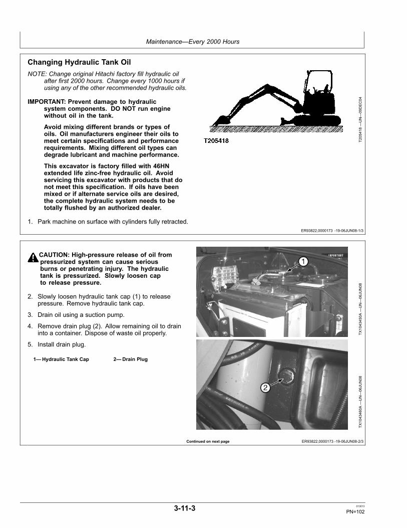
Maintenance—Every 2000 Hours
ER93822,0000173 -19-06JUN08-1/3
Continued on next page ER93822,0000173 -19-06JUN08-2/3
Changing Hydraulic Tank OilNOTE: Change original Hitachi factory fill hydraulic oil
after first 2000 hours. Change every 1000 hours ifusing any of the other recommended hydraulic oils.
IMPORTANT: Prevent damage to hydraulicsystem components. DO NOT run enginewithout oil in the tank.
Avoid mixing different brands or types ofoils. Oil manufacturers engineer their oils tomeet certain specifications and performancerequirements. Mixing different oil types candegrade lubricant and machine performance.
This excavator is factory filled with 46HNextended life zinc-free hydraulic oil. Avoidservicing this excavator with products that donot meet this specification. If oils have beenmixed or if alternate service oils are desired,the complete hydraulic system needs to betotally flushed by an authorized dealer.
1. Park machine on surface with cylinders fully retracted.
T205418—UN—09DEC04
CAUTION: High-pressure release of oil frompressurized system can cause seriousburns or penetrating injury. The hydraulictank is pressurized. Slowly loosen capto release pressure.
2. Slowly loosen hydraulic tank cap (1) to releasepressure. Remove hydraulic tank cap.
3. Drain oil using a suction pump.
4. Remove drain plug (2). Allow remaining oil to draininto a container. Dispose of waste oil properly.
5. Install drain plug.
1—Hydraulic Tank Cap 2—Drain PlugTX
1043450A
—UN—06JU
N08
TX1043460A
—UN—06JU
N08
3-11-3 013013
PN=102

Maintenance—Every 2000 Hours
ER93822,0000173 -19-06JUN08-3/3
6. Add oil until it is between marks on sight gauge (1).(See Section 3-1.)
SpecificationHydraulic Tank—OilCapacity............................................................................................ 87 L
23 gal.
IMPORTANT: Avoid hydraulic pump damage.Hydraulic system must be bled wheneverthe hydraulic oil is changed.
7. Bleed hydraulic system. See Bleeding HydraulicSystem. (Section 4-1.)
1—Sight Gauge
T204977—UN—29NOV04
3-11-4 013013
PN=103

Miscellaneous—Machine
TX,90,FF3116 -19-07SEP06-1/1
TX,90,FF3114 -19-03JAN07-1/1
TX14740,0001C80 -19-08FEB05-1/1
ER93822,00001B2 -19-09JUN08-1/1
Do Not Service or Adjust Injection Nozzlesor High Pressure Fuel PumpIf injection nozzles are not working correctly or are dirty,the engine will not run normally. (See your authorizeddealer for service.)
Changing the injection pump in any way not approved bythe manufacturer will end the warranty. (See your copy ofthe John Deere warranty on this machine.)
Do not service an injection pump that is not operatingcorrectly. (See your authorized injection pump servicecenter.)
Do Not Service Control Valves, Cylinders,Pumps, or MotorsSpecial tools and information are needed to servicecontrol valves, cylinders, pumps, or motors.
If these parts need service, see your authorized dealer.
Cleaning Fuel Tank Inlet ScreenClean screen (1) to remove any debris. Use solvent ordiesel fuel.
Replace screen if damaged.
1—Fuel Tank Inlet Screen
T135186—UN—06NOV00
Check Cab Fresh Air FilterIMPORTANT: Replace filter every 6 cleanings.
1. Open left side access door.
2. Remove fresh air filter (1) from filter case.
3. Inspect filter. Clean or replace if necessary.
4. Clean filter in one of these ways:
a. Tap filter on a flat surface with dirty side down.
CAUTION: Prevent possible injury from flyingchips. Reduce compressed air to less than196 kPa (1.96 bar) (28.4 psi) when using forcleaning purposes. Clear area of bystanders,guard against flying chips, and wear personalprotection equipment including eye protection.
b. Use compressed air opposite to the normal air flow.
c. Wash filter in warm, soapy water. Flush filter. Allowfilter to dry before using heater, defroster, or airconditioner.
TX1043523A
—UN—09JU
N08
1—Fresh Air Filter
5. Install filter.
6. Close left side access door.
4-1-1 013013
PN=104

Miscellaneous—Machine
ER93822,00001B3 -19-09JUN08-1/1
Check Cab Recirculating Air FilterIMPORTANT: Replace filter every 6 cleanings.
1. Remove screw (1) and remove access cover (2).
2. Remove air recirculation filter (3).
3. Inspect filter. Clean or replace if necessary.
4. Clean filter using one of these methods:
a. Tap on a flat surface with dirty side down.
CAUTION: Prevent possible injury from flyingchips. Reduce compressed air to less than196 kPa (1.96 bar) (28.4 psi) when using forcleaning purposes. Clear area of bystanders,guard against flying chips, and wear personalprotection equipment including eye protection.
b. Use compressed air opposite to the normal air flow.
c. Wash filters in warm, soapy water. Flush filters.Allow filters to dry before using heater, defroster, orair conditioner.
5. Install filter.
6. Install cap screw.
TX1043527A
—UN—09JU
N08
TX1043528A
—UN—09JU
N08
1—Screw2—Access Cover
3—Air Recirculation Filter
4-1-2 013013
PN=105

Miscellaneous—Machine
ER93822,00001C1 -19-12JUN08-1/1
ER93822,00001B4 -19-09JUN08-1/1
Check Air Intake Hoses1. Open rear access door (1).
2. Remove bolts (2) to remove access cover (3).
3. Check hose (4) for cracks. Replace as necessary.
4. Tighten clamps.
1—Rear Access Door2—Bolts (5 used)
3—Access Cover4—Air Intake Hose
TX1043908A
—UN—12JU
N08
TX1043909A
—UN—12JU
N08
TX1043910A
—UN—12JU
N08
Clean Air Cleaner Dust ValveIMPORTANT: A missing, damaged, or hardened
dust valve will make the dust cup precleanerineffective, causing very short element life. Valveshould suck closed above 1/3 engine speed.
Open left rear access door.
Squeeze dust valve (1) to remove dust from the air cleaner.
If operating in high dust conditions, squeeze dust valveevery couple of hours of operation to release dust.
1—Air Cleaner Dust Valve
TX1043530A
—UN—09JU
N08
4-1-3 013013
PN=106

Miscellaneous—Machine
ER93822,00001B5 -19-09JUN08-1/1
ER93822,00001C2 -19-12JUN08-1/1
T82,EXMA,I -19-18APR06-1/1
CED,TX14740,6412 -19-10MAY99-1/1
Replace Water Separator Element1. Open right rear access door.
2. Close fuel shutoff valve (1) on top of water separator(2).
3. Turn water separator counterclockwise to remove.
4. Remove element and dispose
5. Install new element. Turn water separator clockwiseby hand until O-ring touches mounting surface.
6. Open fuel shutoff valve.
7. Bleed fuel system. See Bleed Fuel System inMiscellaneous Machine. (Section 4-1.)
TX1043539A
—UN—09JU
N08
1—Fuel Shutoff Valve 2—Water Separator
Prime Fuel System
CAUTION: Avoid personal injury and/or machinedamage. Prime the fuel system using onlythe method described below.
IMPORTANT: Avoid machine damage. Do not usethe starter motor to crank the engine whenpriming the fuel system.
Turn the key switch to the ON positon for 10 to 15seconds. See Key Switch. (Section 2-1.)
Precautions for Alternator and Regulator
When batteries are connected, follow these rules:
1. Disconnect negative (-) battery cable when you workon or near alternator or regulator.
2. Be sure alternator wires are correctly connectedBEFORE you connect batteries.
3. Do not ground alternator output terminal.
4. Do not disconnect or connect any alternator orregulator wires while batteries are connected or whilealternator is operating.
5. Connect batteries or a booster battery in the correctpolarity (positive [+] to positive [+] and negative [-] tonegative [-]).
6. Do not disconnect the batteries when engine isrunning and alternator is charging.
7. Disconnect battery cables before you connect batterycharger to the batteries.
Checking Starter and AlternatorSee your authorized dealer for inspection and repair.
4-1-4 013013
PN=107

Miscellaneous—Machine
Continued on next page DW90712,00003AA -19-21NOV06-1/3
Check Battery Electrolyte Level andTerminals
CAUTION: Battery gas can explode. Keep sparksand flames away from batteries. Use a flashlightto check battery electrolyte level.
NEVER check battery charge by placinga metal object across the posts. Use avoltmeter or hydrometer.
ALWAYS remove grounded (-) battery clampfirst and replace it last.
Sulfuric acid in battery electrolyte ispoisonous. It is strong enough to burn skin,eat holes in clothing, and cause blindnessif splashed into eyes.
Avoid the hazard by:
1. Filling batteries in a well-ventilated area.2. Wearing eye protection and rubber gloves.3. Avoiding breathing fumes when
electrolyte is added.4. Avoiding spilling or dripping electrolyte.5. Use proper jump start procedure.
If you spill acid on yourself:
1. Flush your skin with water.2. Apply baking soda or lime to help
neutralize the acid.3. Flush your eyes with water for 15—30 minutes.
Get medical attention immediately.
If acid is swallowed:
1. Do not induce vomiting.
TS203—UN—23AUG88
2. Drink large amounts of water or milk, butdo not exceed 1.9 L (2 quarts).
3. Get medical attention immediately.
1. Remove battery box cover.
4-1-5 013013
PN=108

Miscellaneous—Machine
DW90712,00003AA -19-21NOV06-2/3
DW90712,00003AA -19-21NOV06-3/3
IMPORTANT: If water is added to batteries duringfreezing weather, batteries must be chargedafter water is added to prevent batteries fromfreezing. Charge battery using a batterycharger or by running the engine.
2. Fill each cell to within specified range with distilledwater. DO NOT overfill.
CAUTION: Prevent possible injury. ALWAYSremove grounded (-) battery clamp firstand replace it last.
3. Disconnect battery clamps, grounded clamp first.
1—Battery Post2—Fill Tube
3—Electrolyte Level Range
T137535—UN—25JAN01
T137536—UN—25JAN01
4. Clean battery terminals (1) and clamps with a stiffbrush.
5. Apply lubricating grease (2) around battery terminalbase only.
6. Install and tighten clamps, grounded clamp last.
1—Battery Terminal 2—Lubricating Grease
T137537—UN—25JAN01
4-1-6 013013
PN=109

Miscellaneous—Machine
Continued on next page TX03679,0001788 -19-25JAN07-1/2
Handling, Checking, and Servicing BatteriesCarefully
CAUTION: Battery gas can explode. Keep sparksand flames away from batteries. Use a flashlightto check battery electrolyte level.
Never check battery charge by placinga metal object across the posts. Use avoltmeter or hydrometer.
Always remove grounded (-) battery clampfirst and replace it last.
Sulfuric acid in battery electrolyte ispoisonous. It is strong enough to burn skin,eat holes in clothing, and cause blindnessif splashed into eyes.
Avoid the hazard by:
1. Filling batteries in a well-ventilated area.2. Wearing eye protection and rubber gloves.3. Avoiding breathing fumes when
electrolyte is added.4. Avoiding spilling or dripping electrolyte.5. Use proper jump start procedure.
If you spill acid on yourself:
1. Flush your skin with water.2. Apply baking soda or lime to help
neutralize the acid.3. Flush your eyes with water for 15—30 minutes.
Get medical attention immediately.
If acid is swallowed:
1. Do not induce vomiting.2. Drink large amounts of water or milk, but
do not exceed 1.9 L (2 quarts).3. Get medical attention immediately.
WARNING: Battery posts, terminals, and relatedaccessories contain lead and lead compounds, chemicalsknown to the State of California to cause cancer andreproductive harm. Wash hands after handling.
If electrolyte spills on the floor, use one of the followingmixtures to neutralize the acid: 0.5 kg (1 lb) baking sodain 4 L (1 gal) water, or 0.47 L (1 pt) household ammonia in4 L (1 gal) water.
TS204—UN—23AUG88
TS203—UN—23AUG88
IMPORTANT: Do not overfill the battery cells.
Check the specific gravity of electrolyte in each battery cell.
4-1-7 013013
PN=110

Miscellaneous—Machine
TX03679,0001788 -19-25JAN07-2/2
OUT4001,0000239 -19-17JUL07-1/1
ER93822,00001B6 -19-09JUN08-1/1
See your authorized dealer for JT05460SERVICEGARD™ battery and coolant tester. Followdirections included with the tester.
A fully charged battery will have a corrected specificgravity reading of 1.260. If the reading is below 1.200,charge the battery.
T85402
—UN—10NOV88
SERVICEGARD is a trademark of Deere & Company
Using Battery Charger
CAUTION: Prevent possible injury from explodingbattery. Do not charge a battery if the batteryis frozen or it may explode. Warm battery to16°C (60°F) before charging.
Turn off charger before connecting ordisconnecting it.
IMPORTANT: Do not use battery charger as abooster if a battery has a 1.150 specificgravity reading or lower.
Disconnect battery ground (-) clamp beforeyou charge batteries in the machine to preventdamage to electrical components.
A battery charger may be used as a booster to start engine.
Ventilate the area where batteries are being charged.
Stop or cut back charging rate if battery case feels hot,or is venting electrolyte. Battery temperature must notexceed 52°C (125°F).
TS204—UN—23AUG88
N36890—UN—07OCT88
Replacing the Battery
Your machine has one 12-volt battery with negative (-)ground. Battery must meet one of the specifications below.
SpecificationBattery—Cold CrankingAmps At -18°C (0°F)................................................................. 799 amps
Replace the failed battery with one of the same type. Forexample, replace a failed maintenance-free battery with anew maintenance-free battery. Different types of batteriesmay have different rates of charge. This difference couldoverload the battery and cause it to fail.
4-1-8 013013
PN=111

Miscellaneous—Machine
OUT4001,00000E1 -19-02JUL09-1/1
OUO1032,00015C0 -19-08DEC04-1/1
TX03679,00017E0 -19-21DEC12-1/1
Using Booster Batteries—12-Volt SystemBefore boost starting, machine must be properly shutdown to prevent unexpected machine movement whenengine starts.
CAUTION: Prevent possible injury from explodingbattery. An explosive gas is produced whilebatteries are in use or being charged. Keep flamesor sparks away from the battery area. Make surethe batteries are charged in a well ventilated area.
IMPORTANT: The machine electrical system isa 12-volt negative (-) ground. Use only12-volt booster batteries.
1. Connect one end of the positive cable to the positiveterminal of the machine batteries and the other end tothe positive terminal of the booster batteries.
2. Connect one end of the negative cable to the negativeterminal of the booster batteries. Connect other endof the negative cable to the machine as far away fromthe machine batteries as possible.
TS204—UN—23AUG88
3. Start engine.
4. Immediately after starting engine disconnect end ofthe negative cable from the machine. Then disconnectthe other end of the negative cable from the negativeterminal of the booster batteries.
5. Disconnect positive cable from booster batteries andmachine batteries.
Welding On Machine
IMPORTANT: Disconnect battery ground strapto prevent voltage spikes throughalternator or monitor.
Disable electrical power before welding.Disconnect positive battery cable. Separateharness connectors to engine and vehiclemicroprocessors.
Do not weld within 12 inches of electroniccomponents. Remove electronic componentsif necessary.
Connect welder ground clamp close toeach weld area so electrical current doesnot arc inside any bearings.
Clean Machine RegularlyRemove any grease, oil, fuel, or debris build-up to avoidpossible injury or machine damage.
IMPORTANT: Directing pressurized water atelectronic/electrical components or connectors,bearings and hydraulic seals, fuel injectionpumps or other sensitive parts and componentsmay cause product malfunctions. Reducepressure and spray at a 45 to 90 degree angle.
High pressure washing (greater than 1379 kPa (13.8bar) (200 psi) can damage freshly painted finishes. Paintshould be allowed to air dry for 30 days minimum afterreceipt of machine before cleaning with high pressure. Uselow pressure wash operations until 30 days have elapsed.
T6642E
J—UN—18OCT88
Do not spray oil cooler fins at an angle. Fins may bend.
4-1-9 013013
PN=112

Miscellaneous—Machine
VD76477,0001541 -19-20JUL12-1/1
OUT4001,00002F1 -19-26JUN07-1/1
JDLink™ Machine Monitoring System(MMS)—If EquippedJDLink™ is an equipment monitoring and informationdelivery system. JDLink™ automatically collects andmanages information about where and how construction
and forestry equipment is being used, as well as criticalmachine health data and service status.
For more information, see your authorized dealer or visitwww.deere.com (browse to Construction, Services andSupport, JDLink™).
JDLink is a trademark of Deere & Company
JDLink™ Machine Monitoring System (MMS)Direct Laptop Connection—If EquippedNOTE: (Location of control box behind the access
door may vary depending on model.)
• Open left door (1) to access JDLink™ MMS.• To download machine data using the JDLink™ MMSDirect:- Install the JDLink™ MMS Direct cable by inserting theEthernet connector into the laptop.
- Connect the JDLink™ MMS Direct cable to the vehicle4-pin Deutsch connector (2).
- Launch JDLink™ MMS Direct Software.• Contact your authorized dealer to obtain the JDLink™MMS Direct Kit (AT347680), which includes theJDLink™ MMS Direct cable (AT335476) and software.
NOTE: On equipment using the JDLink™ Direct system,there is no nightly upload to a remote serverand thus, the information is only stored in onelocation—the controller. Without downloading thecontroller data on a regular basis, the data couldbe lost if the controller were to fail.
To obtain the most detailed machine data onyour laptop, you must perform a machine datadownload every 1000 hrs or less.
1—Left Access Door 2—4-pin Deutsch Connector
TX1025143A
—UN—19JU
N07
350DLC shown
TX1025668A
—UN—07MAR08
JDLink is a trademark of Deere & Company
4-1-10 013013
PN=113

Miscellaneous—Machine
Continued on next page ER93822,00000FF -19-27FEB12-1/2
Replacing FusesThe fuse block is located under the operator seat. Removeaccess cover (1) and fuse block cover (2) to access.
1—Access Cover 2—Fuse Block Cover
TX1043559A
—UN—09JU
N08
TX1043560A
—UN—09JU
N08
4-1-11 013013
PN=114

Miscellaneous—Machine
ER93822,00000FF -19-27FEB12-2/2
IMPORTANT: Install fuse with correct amperagerating to prevent electrical system damagefrom overload.
Fuse (Blade-Type) Color CodesAmperage Rating Color1 Black3 Violet4 Pink5 Tan7-1/2 Brown10 Red15 Light Blue20 Yellow25 Natural (white)30 Light Green
F1—Horn Relay 5 A Fuse(Marked HORN)
F2—Monitor (Backup), Radio(Backup) 5 A Fuse (MarkedRADIO/MONITOR)
F3—Pilot Shut-Off Switch,Buzzer 5 A Fuse (MarkedGATE LOCK BUZZER)
F4—Angle Blade (Optional),Accessory Power Supply10 A Fuse (MarkedOUTLET)
F5—Starter Relay, ECU (StartSignal) 5 A Fuse (MarkedSTART)
F6—Work Light Switch, BlowerMotor Relay 25 A Fuse(Marked BLOWER ILLIMI.)
F7—Radio, Wiper, WasherSwitch 10 A Fuse (MarkedRADIO/WIPER WASHER)
F8—Monitor (Power Supply),Auto Idle (A/I) Controller,Starter Cut Relay, FuelTransfer Pump, Alternator,Injection Pump RackModule, ECU (IgnitionSignal) 10 A Fuse (MarkedENGINE/MONITOR)
F9—Cab Dome Light, TravelSpeed Switch, TravelAlarm Controller, TravelAlarm 5 A Fuse (MarkedTRAVEL AI/ ROOM LAMP)
F10— Not UsedF11— Work Light Relay 20 A
Fuse (Marked WORKLIGHT)
F12— Not UsedF13— Not UsedF14— Not UsedF15— Not UsedF16— Not UsedF17— Not UsedF18— Not Used
F1
F11 F13 F15 F17F12 F14 F16 F18
F10F9F8F7F6F2 F3 F4 F5
TX1041196—UN—28APR08
Fuse Block Layout
4-1-12 013013
PN=115
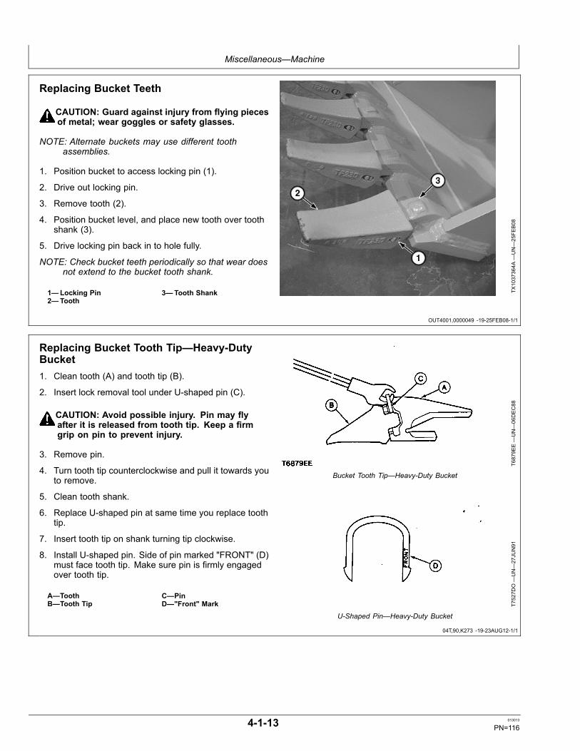
Miscellaneous—Machine
OUT4001,0000049 -19-25FEB08-1/1
04T,90,K273 -19-23AUG12-1/1
Replacing Bucket Teeth
CAUTION: Guard against injury from flying piecesof metal; wear goggles or safety glasses.
NOTE: Alternate buckets may use different toothassemblies.
1. Position bucket to access locking pin (1).
2. Drive out locking pin.
3. Remove tooth (2).
4. Position bucket level, and place new tooth over toothshank (3).
5. Drive locking pin back in to hole fully.
NOTE: Check bucket teeth periodically so that wear doesnot extend to the bucket tooth shank.
1—Locking Pin2—Tooth
3—Tooth Shank TX1037364A
—UN—25FE
B08
Replacing Bucket Tooth Tip—Heavy-DutyBucket1. Clean tooth (A) and tooth tip (B).
2. Insert lock removal tool under U-shaped pin (C).
CAUTION: Avoid possible injury. Pin may flyafter it is released from tooth tip. Keep a firmgrip on pin to prevent injury.
3. Remove pin.
4. Turn tooth tip counterclockwise and pull it towards youto remove.
5. Clean tooth shank.
6. Replace U-shaped pin at same time you replace toothtip.
7. Insert tooth tip on shank turning tip clockwise.
8. Install U-shaped pin. Side of pin marked "FRONT" (D)must face tooth tip. Make sure pin is firmly engagedover tooth tip.
A—ToothB—Tooth Tip
C—PinD—"Front" Mark
T6879E
E—UN—06DEC88
Bucket Tooth Tip—Heavy-Duty Bucket
T7527D
O—UN—27JU
N91
U-Shaped Pin—Heavy-Duty Bucket
4-1-13 013013
PN=116

Miscellaneous—Machine
OUT4001,000003C -19-22FEB08-1/1
04T,90,M197 -19-18JUL06-1/1
TX14740,0001CFC -19-23JAN02-1/1
Removing Bucket1. Lower bucket to the ground.
2. Remove cap screws (1).
3. Slide O-ring seals out of way. Remove bucket pins.
1—Cap Screw (2 used)
TX1037290A
—UN—25FE
B08
Track Sag General Information
To maximize undercarriage life, keep track sag withinspecification. Tracks may require adjustment severaltimes during a working day due to changing soil type andmoisture content.
Adjust tracks in the actual operating conditions.
TIGHT TRACK: Packing causes a tight track. If materialpacks in the undercarriage, adjust tracks with the materialpacked in the components.
While the track spring will recoil and the machine cancontinue to operate with a tight track, continued operationwill result in excessive pin and bushing wear, sprocket
popping, tooth tip wear, and excessive loads on the entireundercarriage and travel drive system.
Machine productivity and fuel consumption are alsoadversely affected because increased horsepower isneeded to move the machine.
LOOSE TRACK: A loose track has more side to sidemotion, increasing side wear on the links, rollers and frontidler. An excessively loose track will slap at high groundspeeds, resulting in high impact loads on the sprocketteeth, bushings, and carrier rollers.
Checking Track Shoe Hardware
Tracks shoes should be checked periodically for looseor missing cap screws and nuts. For shoes with missingor loose cap screws and nuts, remove shoes and cleanthe mating surface of shoes and links before tighteningcap screws and nuts. The cap screws should be replacedbecause they have been stretched to yield previously.
Operating a machine with loose shoes can cause the capscrews and holes in the shoes and links to wear makingit difficult to keep the shoes tight. Loose shoes can alsocause hardware failure and loss of shoes.
1. Clean the mating surface of shoe and links. Installshoes.
2. Apply a light coating of oil to cap screw threads beforeinstalling.
3. Install nuts with the rounded corners against milledsurface of link and chamfered side is away from link.
Check that nuts are square with the milled surface oflink and there is full contact between nut and milledsurface. As necessary, hold the nut so it does not turn.
4. Starting at any cap screw, tighten all cap screws insequence to the torque specification, then 1/2 turn(180°) more.
4-1-14 013013
PN=117

Miscellaneous—Machine
DX,TORQ1 -19-12JAN11-1/1
Unified Inch Bolt and Screw Torque ValuesTS1671 —UN—01MAY03
SAE Grade 1 SAE Grade 2a SAE Grade 5, 5.1 or 5.2 SAE Grade 8 or 8.2Bolt or ScrewSize Lubricatedb Dryc Lubricatedb Dryc Lubricatedb Dryc Lubricatedb Dryc
N·m lb.-in. N·m lb.-in. N·m lb.-in. N·m lb.-in. N·m lb.-in. N·m lb.-in. N·m lb.-in. N·m lb.-in.1/4 3.7 33 4.7 42 6 53 7.5 66 9.5 84 12 106 13.5 120 17 150
N·m lb.-ft. N·m lb.-ft.5/16 7.7 68 9.8 86 12 106 15.5 137 19.5 172 25 221 28 20.5 35 26
N·m lb.-ft. N·m lb.-ft.3/8 13.5 120 17.5 155 22 194 27 240 35 26 44 32.5 49 36 63 46
N·m lb.-ft. N·m lb.-ft. N·m lb.-ft.7/16 22 194 28 20.5 35 26 44 32.5 56 41 70 52 80 59 100 74
N·m lb.-ft.1/2 34 25 42 31 53 39 67 49 85 63 110 80 120 88 155 1159/16 48 35.5 60 45 76 56 95 70 125 92 155 115 175 130 220 1655/8 67 49 85 63 105 77 135 100 170 125 215 160 240 175 305 2253/4 120 88 150 110 190 140 240 175 300 220 380 280 425 315 540 4007/8 190 140 240 175 190 140 240 175 490 360 615 455 690 510 870 6401 285 210 360 265 285 210 360 265 730 540 920 680 1030 760 1300 960
1-1/8 400 300 510 375 400 300 510 375 910 670 1150 850 1450 1075 1850 13501-1/4 570 420 725 535 570 420 725 535 1280 945 1630 1200 2050 1500 2600 19201-3/8 750 550 950 700 750 550 950 700 1700 1250 2140 1580 2700 2000 3400 25001-1/2 990 730 1250 930 990 730 1250 930 2250 1650 2850 2100 3600 2650 4550 3350
Torque values listed are for general use only, based on the strength of the boltor screw. DO NOT use these values if a different torque value or tighteningprocedure is given for a specific application. For plastic insert or crimped steeltype lock nuts, for stainless steel fasteners, or for nuts on U-bolts, see thetightening instructions for the specific application. Shear bolts are designed to failunder predetermined loads. Always replace shear bolts with identical grade.
Replace fasteners with the same or higher grade. If highergrade fasteners are used, tighten these to the strength of theoriginal. Make sure fastener threads are clean and that youproperly start thread engagement. When possible, lubricateplain or zinc plated fasteners other than lock nuts, wheel boltsor wheel nuts, unless different instructions are given for thespecific application.
aGrade 2 applies for hex cap screws (not hex bolts) up to 6 in. (152 mm) long. Grade 1 applies for hex cap screws over 6in. (152 mm) long, and for all other types of bolts and screws of any length.b“Lubricated” means coated with a lubricant such as engine oil, fasteners with phosphate and oil coatings, or 7/8 in.and larger fasteners with JDM F13C, F13F or F13J zinc flake coating.c“Dry” means plain or zinc plated without any lubrication, or 1/4 to 3/4 in. fasteners with JDM F13B, F13E or F13H zinc flake coating.
4-1-15 013013
PN=118

Miscellaneous—Machine
DX,TORQ2 -19-12JAN11-1/1
Metric Bolt and Screw Torque ValuesTS1670 —UN—01MAY03
4.84.8 8.8 9.8 10.9 12.9 12.9
12.912.910.99.88.84.8
Class 4.8 Class 8.8 or 9.8 Class 10.9 Class 12.9Bolt or ScrewSize Lubricateda Dryb Lubricateda Dryb Lubricateda Dryb Lubricateda Dryb
N·m lb.-in. N·m lb.-in. N·m lb.-in. N·m lb.-in. N·m lb.-in. N·m lb.-in. N·m lb.-in. N·m lb.-in.M6 4.7 42 6 53 8.9 79 11.3 100 13 115 16.5 146 15.5 137 19.5 172
N·m lb.-ft. N·m lb.-ft. N·m lb.-ft. N·m lb.-ft.M8 11.5 102 14.5 128 22 194 27.5 243 32 23.5 40 29.5 37 27.5 47 35
N·m lb.-ft. N·m lb.-ft. N·m lb.-ft.M10 23 204 29 21 43 32 55 40 63 46 80 59 75 55 95 70
N·m lb.-ft.M12 40 29.5 50 37 75 55 95 70 110 80 140 105 130 95 165 120M14 63 46 80 59 120 88 150 110 175 130 220 165 205 150 260 190M16 100 74 125 92 190 140 240 175 275 200 350 255 320 235 400 300M18 135 100 170 125 265 195 330 245 375 275 475 350 440 325 560 410M20 190 140 245 180 375 275 475 350 530 390 675 500 625 460 790 580M22 265 195 330 245 510 375 650 480 725 535 920 680 850 625 1080 800M24 330 245 425 315 650 480 820 600 920 680 1150 850 1080 800 1350 1000M27 490 360 625 460 950 700 1200 885 1350 1000 1700 1250 1580 1160 2000 1475M30 660 490 850 625 1290 950 1630 1200 1850 1350 2300 1700 2140 1580 2700 2000M33 900 665 1150 850 1750 1300 2200 1625 2500 1850 3150 2325 2900 2150 3700 2730M36 1150 850 1450 1075 2250 1650 2850 2100 3200 2350 4050 3000 3750 2770 4750 3500
Torque values listed are for general use only, based on the strength ofthe bolt or screw. DO NOT use these values if a different torque value ortightening procedure is given for a specific application. For stainless steelfasteners or for nuts on U-bolts, see the tightening instructions for thespecific application. Tighten plastic insert or crimped steel type lock nutsby turning the nut to the dry torque shown in the chart, unless differentinstructions are given for the specific application.
Shear bolts are designed to fail under predetermined loads. Alwaysreplace shear bolts with identical property class. Replace fasteners withthe same or higher property class. If higher property class fasteners areused, tighten these to the strength of the original. Make sure fastenerthreads are clean and that you properly start thread engagement. Whenpossible, lubricate plain or zinc plated fasteners other than lock nuts,wheel bolts or wheel nuts, unless different instructions are given for thespecific application.
a“Lubricated” means coated with a lubricant such as engine oil, fasteners with phosphate and oil coatings, or M20and larger fasteners with JDM F13C, F13F or F13J zinc flake coating.b“Dry” means plain or zinc plated without any lubrication, or M6 to M18 fasteners with JDM F13B, F13E or F13H zinc flake coating.
4-1-16 013013
PN=119
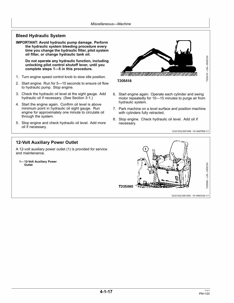
Miscellaneous—Machine
OUO1032,0001599 -19-18APR06-1/1
OUO1032,000159A -19-16NOV04-1/1
Bleed Hydraulic SystemIMPORTANT: Avoid hydraulic pump damage. Perform
the hydraulic system bleeding procedure everytime you change the hydraulic filter, pilot systemoil filter, or change hydraulic tank oil.
Do not operate any hydraulic function, includingunlocking pilot control shutoff lever, until youcomplete steps 1—5 in this procedure.
1. Turn engine speed control knob to slow idle position.
2. Start engine. Run for 5—10 seconds to ensure oil flowto hydraulic pump. Stop engine.
3. Check the hydraulic oil level at the sight gauge. Addhydraulic oil if necessary. (See Section 3-1.)
4. Start the engine again. Confirm oil level is aboveminimum point in hydraulic oil sight gauge. Runengine for approximately one minute to circulate oilthrough the system.
5. Stop engine and check hydraulic oil level. Add moreoil if necessary.
T205418—UN—09DEC04
6. Start engine again. Operate each cylinder and swingmotor repeatedly for 10—15 minutes to purge air fromhydraulic system.
7. Park machine on a level surface and position machinewith cylinders fully retracted.
8. Stop engine. Check hydraulic oil level. Add oil ifnecessary.
12-Volt Auxiliary Power OutletA 12-volt auxiliary power outlet (1) is provided for serviceand maintenance.
1—12-Volt Auxiliary PowerOutlet
T205080—UN—10DEC04
4-1-17 013013
PN=120

Miscellaneous—Machine
ER93822,00001C4 -19-12JUN08-1/1
Cleaning Air Conditioning Condenser andScreens1. Open right access door.
2. Remove two wing screws (1).
3. Remove right condenser screen (2).
4. Remove left condenser screen (3).
5. Clean air conditioner condenser (4) with compressedair. Blow air straight through fins to avoid bendingthem.
6. Wipe off or rinse screens with warm water until clean.
7. Install air conditioning condenser
8. Install left condenser screen.
9. Install right condenser screen.
TX1043949A
—UN—12JU
N08
10. Install two wing screws.
11. Close right access door.
4-1-18 013013
PN=121

Miscellaneous—Machine
Continued on next page OUO1032,00015A6 -19-19NOV04-1/2
Installing Bucket With Quick Coupler1. Position bucket and machine on a flat level surface.
2. Slowly lower boom and maneuver arm to insert armpivot pin (1) into open end of bucket ears (2).
3. Extend bucket cylinder (3) until the square pin boss (4)rests on the flat surface of bucket ears (5).
1—Arm Pivot Pin2—Bucket Ears3—Bucket Cylinder
4—Square Pin Boss5—Bucket Ears
T123697B
—UN—19AUG99
Machine Shown with Optional Thumb Attachment
T123698B
—UN—19AUG99
4-1-19 013013
PN=122

Miscellaneous—Machine
OUO1032,00015A6 -19-19NOV04-2/2
TX,55,DH5376 -19-25JAN07-1/1
Continued on next page OUO1032,000158C -19-18JUL06-1/3
4. Install bucket or attachment and wedge bar (1). Twolynch pins (2) are installed on rear of mechanical quickcoupler.
5. Tighten cap screw (3) to specification.Specification
Cap Screw—Torque....................................................................135 N·m100 lb-ft
1—Wedge Bar2—Lynch Pins
3—Cap Screw
T130378C
—UN—11JU
L00
Rubber Track Care
CAUTION: Prevent possible injury fromunexpected machine movement. A machine withrubber track is less stable than a machine withsteel shoes, as the edge of the rubber trackmay bend when bucket is loaded, especiallywhen digging over the side.
When you drive the machine:
• Do not operate on sharp, rocky, uneven surfaces.
NOTE: The rubber track has a thin rubber film on itsinner surface when it is new. It is normal for thefilm to come off when track rubs against rollers.
• Keep the rubber track free of oil, gasoline, etc. Avoidtraveling on oil to reduce the chance of slipping.• If machine is parked or stored for more than 90 days,park in an area out of direct sunlight.• When transporting a machine with rubber tracks, alwaysfasten the right and left track frames securely to thetrailer. Do not allow tie down chains to come into directcontact with rubber track pads.
Removing and Installing Rubber Track1. Rotate upperstructure so front of upperstructure is
over travel motors (180°).
2. Lower the bucket and blade to raise both tracks offground.
CAUTION: Prevent possible injury fromunexpected machine movement. Place blocksunder machine frame to support machinewhile measuring track sag.
3. Place blocks under machine frame to support machine.
T204990—UN—30NOV04
4-1-20 013013
PN=123

Miscellaneous—Machine
OUO1032,000158C -19-18JUL06-2/3
OUO1032,000158C -19-18JUL06-3/3
CED,TX14740,6459 -19-18APR06-1/1
CAUTION: Prevent possible injury fromhigh-pressure grease. DO NOT remove greasefitting (1) from valve (2).
4. To loosen track, slowly turn valve (2) counterclockwise.Grease will escape through the bleed hole (3).
CAUTION: Prevent potential injury from frontidler. Do not stand in front of idler during removalof track. Front idler may come off unexpectedly.
5. Insert two or three steel pipes (4) into gaps amonglower rollers, track frame, and rubber track. Rotatetrack slowly in reverse to lift track off idler. Pry trackoff idler.
6. Install the rubber track on the sprocket first. Positionthe other end of the rubber track on the front idler.
7. While rotating the sprocket in reverse, push on therubber track to force it on the idler.
1—Grease Fitting2—Valve
3—Bleed Hole4—Steel Pipe
T204989—UN—30NOV04
T204991—UN—30NOV04
8. Insert a steel pipe (4) into gaps among lower rollers,track frame, and rubber track and rotate slowly inreverse to force the rubber track onto the idler.
9. Check that the rubber track is correctly engaged withthe sprocket and idler.
10. Adjust track sag. See Adjusting Track Sag. (Section3-4.)
11. Lower the machine to the ground.
4—Steel Pipe
T204992—UN—30NOV04
Converting the TrackThe rubber track uses a different track adjuster than thatused for the steel track.
CAUTION: Prevent possible injury fromhigh-pressure grease. DO NOT attempt to
disassemble the track adjuster before convertingthe track. See your authorized dealer.
Change the track adjuster whenever converting the track.See your authorized dealer for correct track adjuster.
4-1-21 013013
PN=124

Miscellaneous—Operational Checkout
ER93822,000010F -19-12SEP12-1/33
ER93822,000010F -19-12SEP12-2/33
Continued on next page ER93822,000010F -19-12SEP12-3/33
Operational CheckoutThis procedure is used to check operation of the machine.It is written so a technician can do a walk-aroundinspection, check machine operation, and perform specificchecks from the operator’s seat.
If there is a problem with the machine, diagnosticinformation in this checkout will help determine theprobable cause. This information can direct a technician toperform a simple adjustment to correct the problem. Usethe table of contents to help find adjustment procedures.
Machine is positioned so it is level and there is adequatespace to complete the checks. No tools are needed toperform the checkout.
Complete the usual necessary visual checks (oil levels, oilcondition, external leaks, loose hardware, linkage, wiring)prior to doing the checkout. The machine must be atoperating temperature for many of the checks.
Read each check completely before performing. Thenperform check, and if no problem is found, you willbe instructed to go to the next check. If a problem isindicated, you will be referred to either a section withinthis manual or to your authorized dealer for repair.
Ignition OFF, Engine OFF Checks
Horn Circuit Check
1
TX1095438 —UN—30AUG11Horn Button
1—Horn Button
Key switch OFF. YES: Check complete.Push horn button on top of right control lever. NO: Check fuse (F1)
(marked HORN). See Fuseand Relay Specifications.(Section 4-1.)
LISTEN: Does horn activate? NO: Check switch, wiring,and connections. See yourauthorized dealer
4-2-1 013013
PN=125

Miscellaneous—Operational Checkout
Continued on next page ER93822,000010F -19-12SEP12-4/33
Hour Meter and FuelGauge Check
12
3
TX1095442 —UN—23AUG11Monitor Panel (S.N. —280538) Shown
1—Hour Meter2—Fuel Gauge3—Display Select Button
Push and hold display select button (3). YES: Check complete.LOOK: Does the hour meter (1) display machine hours? NO: Check fuse (F2)
(marked RADIO/MONITORB). See Fuse and RelaySpecifications. (Section4-1.)
LOOK: Does fuel gauge (2) display a fuel level? NO: Check wiring andconnections. See yourauthorized dealer.
4-2-2 013013
PN=126

Miscellaneous—Operational Checkout
ER93822,000010F -19-12SEP12-5/33
ER93822,000010F -19-12SEP12-6/33
Continued on next page ER93822,000010F -19-12SEP12-7/33
Travel Lever and PedalNeutral Check
3
1
2
TX1095451 —UN—22AUG11Travel Levers and Pedals
1—Travel Forward2—Travel Rearward3—Pilot Shutoff Lever
Push each travel lever forward, then release.Pull each travel lever rearward, then release.FEEL: Does each lever have equal effort to operate forward and reverse? YES: Check complete.FEEL/LOOK: Does each lever return to neutral at the same time when released? NO: Repair or replace
pilot controller. See yourauthorized dealer.
Ignition ON, Engine OFF Checks
Monitor Indicators andGauge Circuit Check
NOTE: For identification of monitor indicators and gauges on machines (S.N.—280538), see Monitor Panel and Functions (S.N. —280538). (Section 2-1.)
For identification of monitor indicators and gauges on machines (S.N. 280539—), see Monitor Panel and Functions (S.N. 280539— ). (Section 2-1.)
Monitor alarm is not checked during this procedure.Turn key switch to ON position.If engine coolant temperature is below 30°C (86°F), engine temperature gauge segmentmay not come on. Run engine a few minutes to warm coolant before check.
YES: Check complete.
LOOK: Do engine coolant temperature gauge and fuel gauge segments come on? NO: If any monitor lightfails to come on, check andreplace bulb.
If all monitor lights failto come on, check fuses(F2 and F8). See Fuseand Relay Specifications.(Section 4-1.)
LOOK: Do all monitor lights come on and after 2—3 seconds only the alternatorindicator and engine oil pressure indicator light remain on?
NO: Check wiring. Seeyour authorized dealer.
4-2-3 013013
PN=127

Miscellaneous—Operational Checkout
Continued on next page ER93822,000010F -19-12SEP12-8/33
Engine Preheat CircuitCheck—Cold WeatherOnly
NOTE: The preheat system is a timed system based on engine coolanttemperature. The engine coolant temperature must be less than or equalto 0°C (32°F) for the preheat system to operate.
Turn key switch to the ON position. YES: Check complete.Does the engine preheat indicator light come ON, then go OFF after the approximateamount of time elapses as indicated by the following table?
NO: Check engine coolanttemperature sensor (B4),wires, and connections.See your authorized dealer.
Engine CoolantTemperature
Preheat Time(approximate)
0°C (32°F) or higher 1.5 Seconds-7°C (19.4°F) 10 Seconds-10°C (14°F) 15 Seconds-15°C (5°F) 20 Seconds
-20°C (-4°F) or lower 24 Seconds
NO: If preheat indicatoractivates correctly butengine does not start oris hard to start in coldconditions, check fuses(F62 and F63). See Fuseand Relay Specifications.(Section 4-1.)
If fuses OK, check intake airheater relay (K17), intakeair preheater (R1 and R2),wires, and connections.See your authorized dealer.
4-2-4 013013
PN=128

Miscellaneous—Operational Checkout
Continued on next page ER93822,000010F -19-12SEP12-9/33
Light Circuit Check
1 2 3 4 5 6
7
TX1095453 —UN—15AUG11Switch Panel (S.N. —280538) Shown
1—Key Switch2—Engine Speed Dial3—Travel Speed Switch4—Work Light Switch5—Windshield Wiper and Washer Switch6—Travel Alarm Cancel Switch7—Power Mode Switch
NOTE: All accessories are powered from the fuse block. If any accessoriesdo not function, check fuses in fuse block.
Turn key switch (1) ON.Push work light switch (4) to ON position.LOOK: Are the work lights on the boom and left front corner of upperstructure ON?Push work light switch to OFF position. YES: Check complete.LOOK: Do all the lights go OFF? NO: Check fuse (F6)
(marked WORK LIGHTS).See Fuse and RelaySpecifications. (Section4-1.)
Check wiring andconnections. See yourauthorized dealer.
4-2-5 013013
PN=129

Miscellaneous—Operational Checkout
Continued on next page ER93822,000010F -19-12SEP12-10/33
Wiper Circuit Check1 2 3 4 5 6
TX1095457 —UN—15AUG11Windshield Wiper Switch
1—Key Switch2—Engine Speed Dial3—Travel Speed Switch4—Work Light Switch5—Windshield Wiper and Washer Switch6—Travel Alarm Cancel Switch
NOTE: Ensure upper front window is fully down and latched in place. Wiper interlockswitch will prevent operation if window is not secured.
Key switch (1) ON.Push wiper switch (5) to ON position.LOOK: Does wiper operate continuously?Push wiper switch to ON position. YES: Check complete.LOOK: Does wiper arm stop in park position at left side of window? NO: Check fuse
(F7) (marked (RA-DIO/WIPER/WASHER).See Fuse and Relay Speci-fications. (Section 4-1.)
Check wiring andconnections. See yourauthorized dealer.
4-2-6 013013
PN=130
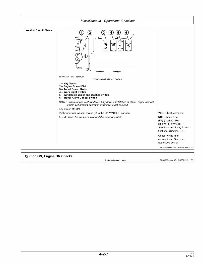
Miscellaneous—Operational Checkout
ER93822,000010F -19-12SEP12-11/33
Continued on next page ER93822,000010F -19-12SEP12-12/33
Washer Circuit Check1 2 3 4 5 6
TX1095457 —UN—15AUG11Windshield Wiper Switch
1—Key Switch2—Engine Speed Dial3—Travel Speed Switch4—Work Light Switch5—Windshield Wiper and Washer Switch6—Travel Alarm Cancel Switch
NOTE: Ensure upper front window is fully down and latched in place. Wiper interlockswitch will prevent operation if window is not secured.
Key switch (1) ON.Push wiper and washer switch (5) to the ON/WASHER position. YES: Check complete.LOOK: Does the washer motor and the wiper operate? NO: Check fuse
(F7) (marked (RA-DIO/WIPER/WASHER).See Fuse and Relay Speci-fications. (Section 4-1.)
Check wiring andconnections. See yourauthorized dealer.
Ignition ON, Engine ON Checks
4-2-7 013013
PN=131

Miscellaneous—Operational Checkout
Continued on next page ER93822,000010F -19-12SEP12-13/33
Monitor Indicators andGauge Circuit Check
IMPORTANT: Stop engine if any one of the following indicators are on:
• Engine oil indicator• Alternator voltage indicator• High coolant temperature indicator• System failure indicator
NOTE: For identification of monitor indicators and gauges on machines (S.N.—280538), see Monitor Panel and Functions (S.N. —280538). (Section 2-1.)
For identification of monitor indicators and gauges on machines (S.N. 280539—), see Monitor Panel and Functions (S.N. 280539— ). (Section 2-1.)
Start engine.LOOK: Do alternator voltage and engine oil pressure indicators go OFF after enginestarts?LOOK: Do all monitor indicators remain OFF after engine starts? YES: Check complete.NOTE: When the coolant temperature is lower than 20°C (68°F), the
first segment will flash.NO: Check fluid levels(engine oil and coolant).
If engine oil pressureindicator is on after enginestarts, see your authorizeddealer.
LOOK: Are engine coolant temperature gauge segments in normal operating zoneafter a few minutes?
NO: If alternator voltageindicator is on after enginestarts, test alternator output.See Alternator Test. (Group9015-20.)
Check belt tension. SeeCheck and Adjust Fan BeltTension. (Section 3-6.)
4-2-8 013013
PN=132
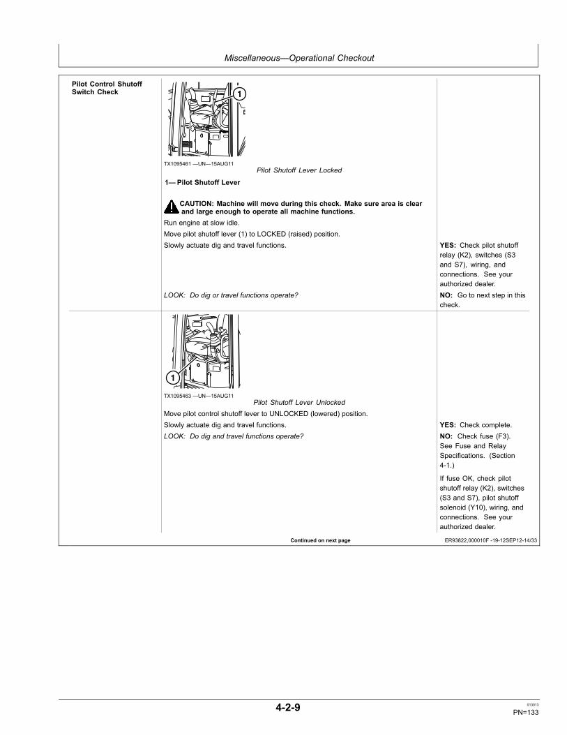
Miscellaneous—Operational Checkout
Continued on next page ER93822,000010F -19-12SEP12-14/33
Pilot Control ShutoffSwitch Check 1
TX1095461 —UN—15AUG11Pilot Shutoff Lever Locked
1—Pilot Shutoff Lever
CAUTION: Machine will move during this check. Make sure area is clearand large enough to operate all machine functions.
Run engine at slow idle.Move pilot shutoff lever (1) to LOCKED (raised) position.Slowly actuate dig and travel functions. YES: Check pilot shutoff
relay (K2), switches (S3and S7), wiring, andconnections. See yourauthorized dealer.
LOOK: Do dig or travel functions operate? NO: Go to next step in thischeck.
1
TX1095463 —UN—15AUG11Pilot Shutoff Lever Unlocked
Move pilot control shutoff lever to UNLOCKED (lowered) position.Slowly actuate dig and travel functions. YES: Check complete.LOOK: Do dig and travel functions operate? NO: Check fuse (F3).
See Fuse and RelaySpecifications. (Section4-1.)
If fuse OK, check pilotshutoff relay (K2), switches(S3 and S7), pilot shutoffsolenoid (Y10), wiring, andconnections. See yourauthorized dealer.
4-2-9 013013
PN=133

Miscellaneous—Operational Checkout
Continued on next page ER93822,000010F -19-12SEP12-15/33
Engine Speed Dial Check1 2 3 4 5 6
TX1095457 —UN—15AUG11Switch Panel (S.N. —280538) Shown
8
9
TX1095467 —UN—11AUG11Monitor (S.N. —280538) Shown
1—Key Switch2—Engine Speed Dial3—Travel Speed Switch4—Work Light Switch5—Windshield Wiper and Washer Switch6—Travel Alarm Cancel Switch8—Auto-Idle Indicator9—Auto-Idle Switch
Disengage auto-idle by pushing auto-idle switch (9) on monitor (S.N. —280538) or theauto-idle switch located on right console (S.N. 280539— ).Move pilot shutoff lever to the LOCKED (raised) position.Turn engine speed dial (2) clockwise to fast idle position.LISTEN: Does engine speed increase?Turn engine speed dial counterclockwise to slow idle position. YES: Go to next step in this
check.LISTEN: Does engine speed decrease? NO: Check engine
speed dial, wiring, andconnections. See yourauthorized dealer.
4-2-10 013013
PN=134

Miscellaneous—Operational Checkout
Continued on next page ER93822,000010F -19-12SEP12-16/33
E (Economy) Mode and P(Standard) Mode Check
1 2 3 4 5 6
7
TX1095453 —UN—15AUG11Switch Panel (S.N. —280538) Shown
8
9
TX1095467 —UN—11AUG11Monitor (S.N. —280538) Shown
1—Key Switch2—Engine Speed Dial3—Travel Speed Switch4—Work Light Switch5—Windshield Wiper and Washer Switch6—Travel Alarm Cancel Switch7—Power Mode Switch8—Auto-Idle Indicator9—Auto-Idle Switch
Push power mode switch (7) to P (standard) mode.Disengage auto-idle by pushing auto-idle switch (9) on monitor (S.N. —280538) or theauto-idle switch located on right console (S.N. 280539— ).Turn engine speed dial (2) clockwise to fast idle position.Push power mode switch to E (economy) mode.LISTEN: Does engine speed decrease?Push power mode switch to P (standard) mode. YES: Check complete.LISTEN: Does engine speed increase? NO: Check power mode
switch, wiring, andconnections. See yourauthorized dealer.
4-2-11 013013
PN=135

Miscellaneous—Operational Checkout
Continued on next page ER93822,000010F -19-12SEP12-17/33
Auto-Idle Circuit Check
1 2 3 4 5 6
7
TX1095453 —UN—15AUG11Switch Panel (S.N. —280538) Shown
8
9
TX1095467 —UN—11AUG11Monitor (S.N. —280538) Shown
1—Key Switch2—Engine Speed Dial3—Travel Speed Switch4—Work Light Switch5—Windshield Wiper and Washer Switch6—Travel Alarm Cancel Switch7—Power Mode Switch8—Auto-Idle Indicator9—Auto-Idle switch
Turn engine speed dial (2) clockwise to (fast idle) position.Push power mode switch (7) to P (standard) mode.Move pilot shutoff lever to UNLOCKED (lowered) position.Engage auto-idle by pushing auto-idle switch (9) on monitor (S.N. —280538) or theauto-idle switch located on right console (S.N. 280539— ).LOOK: Does auto-idle indicator (8) come on?LOOK/LISTEN: Does engine speed decrease when no hydraulic functions areoperated for at least 4—6 seconds?Slowly actuate dig function. YES: Check complete.LISTEN: Does engine speed return to fast idle. NO: See your authorized
dealer.
4-2-12 013013
PN=136

Miscellaneous—Operational Checkout
Continued on next page ER93822,000010F -19-12SEP12-18/33
Travel Alarm CircuitCheck CAUTION: Machine will move during this check. Make sure area is
clear and large enough to operate the machine.
3
1
2
TX1095451 —UN—22AUG11Operator's Station
1—Travel Forward2—Travel Rearward3—Pilot Shutoff LeverMove pilot shutoff lever (3) to the UNLOCKED (lowered) position.Slowly push travel levers or pedals forward (1).LISTEN: Does travel alarm activate?Slowly pull travel levers or push pedals rearward (2). YES: Check complete.LISTEN: Does travel alarm activate? NO: Check fuse (F8)
(marked ENGINE/MONI-TOR). See Fuse and RelaySpecifications. (Section4-1.)
Check travel alarm (H4),travel pressure sensor(B34), travel alarmcontroller (A8), wiring,and connections. See yourauthorized dealer.
4-2-13 013013
PN=137

Miscellaneous—Operational Checkout
Continued on next page ER93822,000010F -19-12SEP12-19/33
Travel Alarm CancelSwitch Check 1 2 3 4 5 6
TX1095457 —UN—15AUG11Switch Panel
1—Key Switch2—Engine Speed Dial3—Travel Speed Switch4—Work Light Switch5—Windshield Wiper and Washer Switch6—Travel Alarm Cancel Switch
CAUTION: Machine will move during this check. Make sure area isclear and large enough to operate the machine.
NOTE: Travel alarm must operate for this check.Push travel lever or pedals forward and allow travel alarm to operate for a minimumof 12 seconds.LISTEN: Does travel alarm activate?While continuing travel, push travel alarm cancel switch (6).LISTEN: Does travel alarm deactivate? YES: Check complete.Return travel levers or pedals to neutral and slowly pull travel levers or push pedalsrearward.
NO: Check fuse (F8)(marked ENGINE/MONI-TOR). See Fuse and RelaySpecifications. (Section4-1.)
LISTEN: Does travel alarm activate again? NO: Check travel alarmcancel switch (S13), wiring,and connections. See yourauthorized dealer.
4-2-14 013013
PN=138

Miscellaneous—Operational Checkout
Continued on next page ER93822,000010F -19-12SEP12-20/33
Hydraulic Oil TankPressurization Check
1
2
TX1041324 —UN—06MAY08Hydraulic Oil Tank Cap
1—Hydraulic Oil Tank2—Hydraulic Oil Tank Cap
Engine running.Raise boom to full height, then lower boom to ground.Stop engine.Slowly loosen oil tank cap (2) on top of hydraulic tank cover.LISTEN: Is air heard escaping from under the cap? YES: Check complete.IMPORTANT: Avoid pump damage. The pressurized hydraulic oil tank creates
pressure at the inlet to the hydraulic pumps. If the filler cap does not sealcorrectly, the hydraulic pumps could cavitate and damage the pumps.
NO: Replace hydraulic oiltank cap.
4-2-15 013013
PN=139

Miscellaneous—Operational Checkout
Continued on next page ER93822,000010F -19-12SEP12-21/33
Pilot Controller PatternCheck—ISO ExcavatorPattern
TX1040369A —UN—15APR08Pattern Selector Valve
Excavator Pattern Backhoe Pattern
FAMILIARIZE YOURSELF WITH THE PATTERN SELECTED BY OPERATING SLOWLY.CAUTION
4 5
TX1079571 —UN—02AUG10
1—Pilot Control Pattern Lever Selector2—Excavator Position3—Backhoe Position4—Excavator Pattern5—Backhoe Pattern
CAUTION: Machine will move during this check. Make sure area isclear and large enough to operate the machine.
Stop engine.Move pilot control pattern lever selector (1) to excavator position (2).Turn engine speed control dial counterclockwise to slow idle. Start engine.Push pilot shutoff lever to UNLOCKED position. Slowly move control levers to allexcavator pattern (4) on decal.
YES: Check complete.
LOOK: Do bucket, boom, arm, and swing move as shown on decal? NO: Check pilot controllerpattern conversion valveposition.
Check line connections.See your authorized dealer.
4-2-16 013013
PN=140
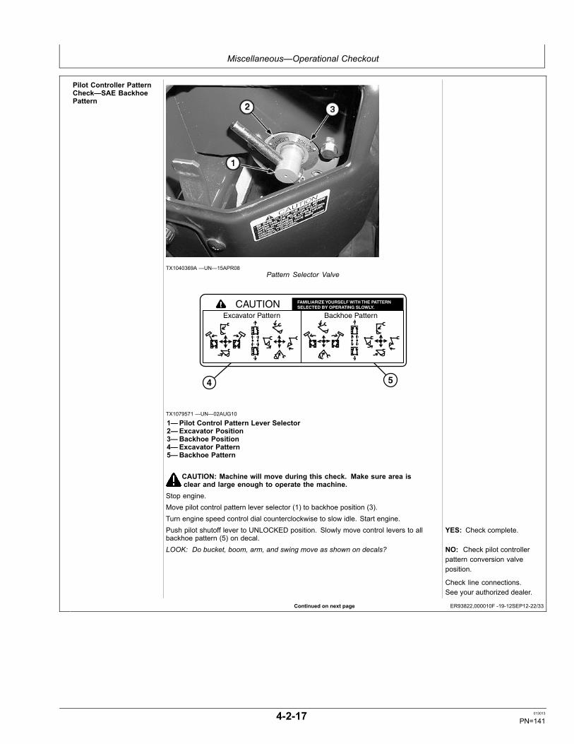
Miscellaneous—Operational Checkout
Continued on next page ER93822,000010F -19-12SEP12-22/33
Pilot Controller PatternCheck—SAE BackhoePattern
TX1040369A —UN—15APR08Pattern Selector Valve
Excavator Pattern Backhoe Pattern
FAMILIARIZE YOURSELF WITH THE PATTERN SELECTED BY OPERATING SLOWLY.CAUTION
4 5
TX1079571 —UN—02AUG10
1—Pilot Control Pattern Lever Selector2—Excavator Position3—Backhoe Position4—Excavator Pattern5—Backhoe Pattern
CAUTION: Machine will move during this check. Make sure area isclear and large enough to operate the machine.
Stop engine.Move pilot control pattern lever selector (1) to backhoe position (3).Turn engine speed control dial counterclockwise to slow idle. Start engine.Push pilot shutoff lever to UNLOCKED position. Slowly move control levers to allbackhoe pattern (5) on decal.
YES: Check complete.
LOOK: Do bucket, boom, arm, and swing move as shown on decals? NO: Check pilot controllerpattern conversion valveposition.
Check line connections.See your authorized dealer.
4-2-17 013013
PN=141

Miscellaneous—Operational Checkout
Continued on next page ER93822,000010F -19-12SEP12-23/33
Swing Dynamic BrakingCheck
45˚
90˚
TX1095482 —UN—10AUG11
CAUTION: Machine will move during this check. Make sure area isclear and large enough to operate the machine.
Position upperstructure with boom in front.Move arm to extended position, bucket to the retracted (curl in) position, andbucket-to-arm pivot pin at the same height as boom-to-frame pivot pin.Turn engine speed dial clockwise to fast idle position.Push power mode switch to P (standard) mode position.Fully actuate swing function. Swing right 90 degrees (1/4 turn) and then release lever.LOOK: Does upperstructure stop within 45 degrees (1/8 turn) or less after releasinglever?Position upperstructure with boom to the front. YES: Check complete.Fully actuate swing function. Swing left 90 degrees and then release lever. NO: Check swing motor.
See your authorized dealer.LOOK: Does upperstructure stop within 45 degrees (1/8 turn) or less after releasinglever?
NO: Check swing valvespool. See your authorizeddealer.
4-2-18 013013
PN=142

Miscellaneous—Operational Checkout
Continued on next page ER93822,000010F -19-12SEP12-24/33
Dig Function Drift Check
TX1095417 —UN—31AUG11Dig Function Drift Test
CAUTION: Machine will move during this check. Make sure area isclear and large enough to operate the machine.
Fill bucket with dirt.Position bucket at maximum reach with bucket pivot pin at the same height as boompivot pin.Retract arm cylinder, then extend about 50 mm (2.00 in.).Extend bucket cylinder, then retract about 50 mm (2.00 in.).Retract blade cylinder, then extend about 50 mm (2.00 in.).Stop engine.Measure amount cylinders extend or retract in 5 minutes.
SpecificationBoom Cylinder—Drift.............................................................................................. 5 mm
0.2 in.Arm Cylinder—Drift............................................................................................... 10 mm
0.4 in.Bucket Cylinder—Drift............................................................................................. 5 mm
0.2 in.Bottom of Bucket-To-Ground—Drift.................................................................... 100 mm
3.94 in.Blade Cylinder—Drift.............................................................................................. 5 mm
0.2 in.Bottom of Blade-To-Ground—Drift........................................................................ 15 mm
0.6 in.Boom Swing Cylinder—Drift................................................................................... 3 mm
0.12 in.
YES: Check complete.
LOOK: Is cylinder drift within specification? NO: See your authorizeddealer.
See your authorized dealer.
4-2-19 013013
PN=143
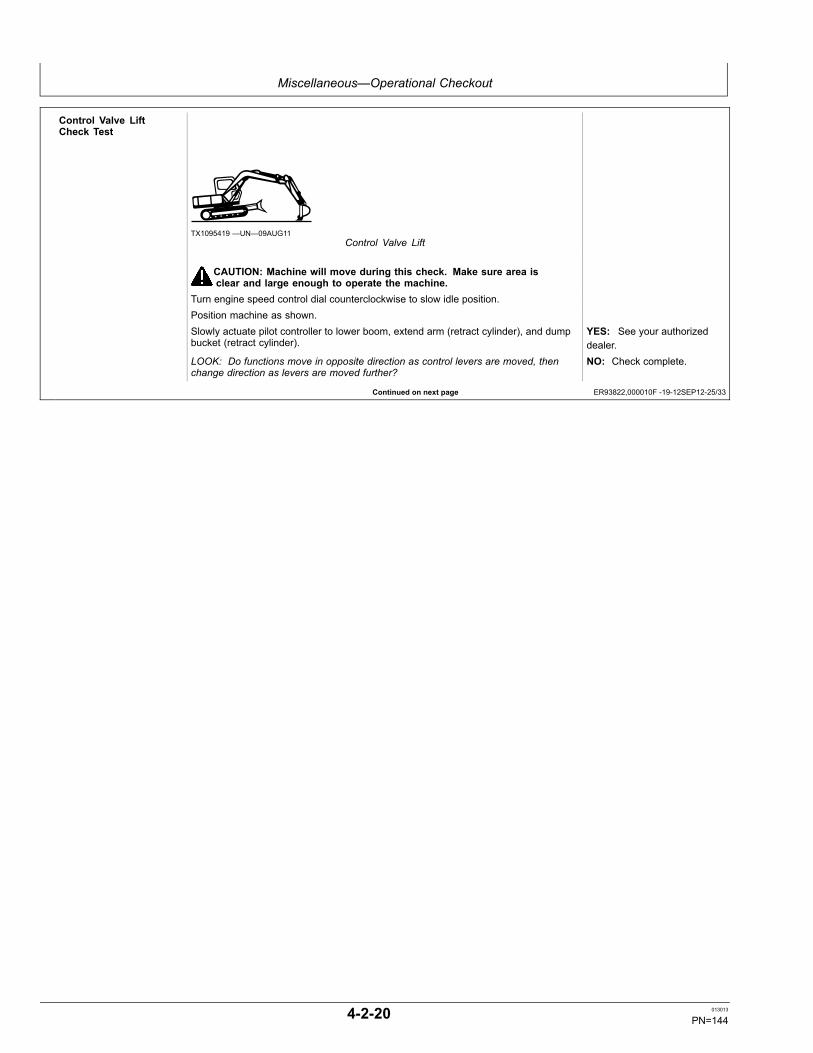
Miscellaneous—Operational Checkout
Continued on next page ER93822,000010F -19-12SEP12-25/33
Control Valve LiftCheck Test
TX1095419 —UN—09AUG11Control Valve Lift
CAUTION: Machine will move during this check. Make sure area isclear and large enough to operate the machine.
Turn engine speed control dial counterclockwise to slow idle position.Position machine as shown.Slowly actuate pilot controller to lower boom, extend arm (retract cylinder), and dumpbucket (retract cylinder).
YES: See your authorizeddealer.
LOOK: Do functions move in opposite direction as control levers are moved, thenchange direction as levers are moved further?
NO: Check complete.
4-2-20 013013
PN=144

Miscellaneous—Operational Checkout
Continued on next page ER93822,000010F -19-12SEP12-26/33
Travel Speed ChangeCheck 1 2 3 4 5 6
TX1095457 —UN—15AUG11Switch Panel
1—Key Switch2—Engine Speed Dial3—Travel Speed Switch4—Work Light Switch5—Windshield Wiper and Washer Switch6—Travel Alarm Cancel Switch
CAUTION: Machine will move during this check. Make sure area isclear and large enough to operate the machine.
Turn engine speed dial (2) clockwise to fast idle position.Push travel speed switch (3) to slow speed (turtle) mode.Actuate travel function to full speed forward.Push travel speed switch to fast speed (rabbit) mode.FEEL/LOOK: Does machine travel speed increase?Actuate a dig function and then return to neutral.FEEL/LOOK: Does machine travel speed decrease and then increase as the digfunction is actuated and released?Push travel speed switch to slow speed (turtle) mode. YES: Check complete.FEEL/LOOK: Does machine travel speed decrease? NO: Check travel speed
solenoid. Check switch,wiring, and connections.See your authorized dealer.
Check travel speed changevalve. See your authorizeddealer.
4-2-21 013013
PN=145

Miscellaneous—Operational Checkout
Continued on next page ER93822,000010F -19-12SEP12-27/33
Travel System TrackingCheck
TX1122400 —UN—12SEP12Switch Panel (S.N. 280539—) Shown
1—Engine Speed Dial2—Travel Speed Switch3—Auto-idle switch4—Power Mode Switch
CAUTION: Machine will move during this check. Make sure area isclear and large enough to operate the machine.
Turn engine speed dial (1) clockwise to (fast idle) position.Turn auto-idle switch (3) OFF.Push power mode switch (4) to P (standard) mode.Push travel speed switch (2) to fast speed (rabbit) mode.
6
6
7
8
5
TX1120481 —UN—17AUG12Tracking Check
5—Distance of Mistrack6—Acceleration and Deceleration Zone (approximately): 3—5 m (10—16 ft.)7—Test Line (distance): 20 m (66 ft.)8—Track Print
Operate machine at full travel forward speed on a flat and level surface approximately30 m (99 ft.).NOTE: When machine mistracks right, hydraulic pump 1 circuit oil flow may be
less than specification. When machine mistracks left, hydraulic pump2 circuit oil flow may be less than specification.
Observe direction of mistrack.Create a straight test line 20 m (66 ft.) (7) long between two points on track print (8).
4-2-22 013013
PN=146

Miscellaneous—Operational Checkout
ER93822,000010F -19-12SEP12-28/33
Continued on next page ER93822,000010F -19-12SEP12-29/33
Measure and record greatest distance of mistrack (5) between inside edge of trackprint and test line.Repeat procedure in reverse travel. YES: Check complete.LOOK: Does machine mistrack less than 200 mm (7.88 in.)? NO: Check travel motors.
See your authorized dealer.
Check main pump flow. Seeyour authorized dealer.
Blade Function CheckCAUTION: Machine will move during this check. Make sure area isclear and large enough to operate the machine.
1
TX1041351 —UN—19SEP08Blade Control Lever
1—Blade Control Lever
Turn engine speed control dial counterclockwise to (slow idle) position.Pull blade control lever (1) rearward.LOOK: Does blade raise?Release lever.LOOK: Does lever return to neutral and the blade stop?Push lever forward.LOOK: Does blade lower?Release lever. YES: Check complete.LOOK/FEEL: Does lever return to neutral and the blade stop? NO: Check blade pilot
controller. See yourauthorized dealer.
Check blade valve spool.See your authorized dealer.
4-2-23 013013
PN=147

Miscellaneous—Operational Checkout
Continued on next page ER93822,000010F -19-12SEP12-30/33
Angle Blade FunctionCheck
TX1101323 —UN—28FEB12Angle Blade Control Lever and Switches
168— Angle Blade Control Lever170— Angle Blade Angle Left Switch171— Angle Blade Angle Right Switch
Pull angle blade control lever (168) rearward.Press angle blade angle left switch (170).LOOK: Does blade angle to the left?Release switchLOOK: Does blade stop?Press angle blade angle right switch (171).LOOK: Does blade angle to the right?Release switch. YES: Check complete.LOOK: Does blade stop? NO: Check angle blade
angle left relay (K18) andangle blade angle right relay(K19). See your authorizeddealer.
Check angle blade angle leftsolenoid (Y27) and angleblade angle right solenoid(Y29). See your authorizeddealer.
4-2-24 013013
PN=148

Miscellaneous—Operational Checkout
Continued on next page ER93822,000010F -19-12SEP12-31/33
Cycle Times CheckCAUTION: Make sure area is clear and large enough to oper-ate all functions of machine.
IMPORTANT: Warm hydraulic oil to operating temperature for this check.Turn engine speed dial clockwise to fast idle position.Record cycle time for each function.
TX1095417 —UN—31AUG11Boom, Arm, Bucket, and Blade
Cycle Times—SpecificationBoom Raise (cylinder extend)—CycleTime............................................................................................................2.0—2.6 sec.Boom Lower (cylinder retract)—CycleTime............................................................................................................2.5—3.1 sec.Arm In (cylinder extend)—Cycle Time........................................................2.3—3.3 sec.Arm Out (cylinder retract)—Cycle Time......................................................2.0—2.6 sec.Bucket Load (cylinder extend)—CycleTime............................................................................................................2.4—3.0 sec.Bucket Dump (cylinder retract)—CycleTime............................................................................................................1.9—2.5 sec.Boom Swing Right (cylinderextend)—Cycle Time..................................................................................6.5—7.5 sec.Boom Swing Left (cylinderretract)—Cycle Time...................................................................................6.5—7.5 sec.Blade Raise—Cycle Time...........................................................................2.1—3.1 sec.Blade Lower—Cycle Time..........................................................................3.1—4.1 sec.Blade Angle Left—Cycle Time....................................................................1.5—2.5 sec.Blade Angle Right—Cycle Time..................................................................1.3—2.3 sec.
Swing Function—SpecificationSwing Left or Right, 3 Revolutions Froma Running Start—Cycle Time.................................................................17.4—20.4 sec.
Travel Function—SpecificationTravel 20 m (66 ft.) From a Running Start(check in forward and reverse with travelspeed switch in FAST position)—CycleTime............................................................................ 14.5—17.5 sec. with rubber track
15.7—18.7 sec. with steel trackTravel 20 m (66 ft.) From a Running Start(check in forward and reverse with travelspeed switch in SLOW position)—CycleTime............................................................................ 26.2—29.2 sec. with rubber track
28.2—31.2 sec. with steel track
YES: Check complete.
LOOK: Does machine perform within specifications? NO: See your authorizeddealer.
4-2-25 013013
PN=149

Miscellaneous—Operational Checkout
Continued on next page ER93822,000010F -19-12SEP12-32/33
Heater and AirConditioner Circuit Check
7 6 5 4 3 2
9 8 10 13
TX1095472 —UN—11AUG11Air Conditioner and Heater Control Panel
12
11
13
11
14
TX1095474 —UN—12AUG11Air Conditioner and Heater Air Vents
1—A/C Switch2—Air Conditioner/Heater Control Power Switch3—Blower Speed Switch4—A/C Indicator5—Temperature Control Switch6—Vent Mode Indicator7—Defroster Switch8—Vent Mode Switch9—Circulation and Fresh Air Mode Switch10— Air Conditioner/Heater LCD Display11— Foot Air Vent12— Lower Front Air Vent13— Upper Front Air Vent14— Rear Air Vent
With engine running and at normal operating temperature.Push air conditioner/heater control power switch (2) ON.LOOK: Does air conditioning/heater LCD display (10) light up?Push the blower speed button (3) to increment through all four fan speeds.FEEL/LISTEN: Does blower motor have four speeds?Put blower speed to highest speed setting.
4-2-26 013013
PN=150

Miscellaneous—Operational Checkout
ER93822,000010F -19-12SEP12-33/33
18
17
16
15
TX1095476 —UN—11AUG11Vent Mode Display
15— Upper Front Air Vent (13)16— Upper Front and Rear Air Vent (13 and 14)17— All Air Vents (11—14)18— Foot and Lower Front Air Vent (11 and 12)
Push vent mode switch (8) to display position (15).FEEL: Does air flow through the upper front vent?Push vent mode button again.FEEL: Does air flow through upper and rear vent?Push vent mode button again.FEEL: Does air flow through all vents (11—14)?Push vent mode button again.FEEL: Does air flow through lower and foot vent.Push temperature control switch (5) up arrow to for warm air.FEEL: Does warm air flow from vents?Push A/C ON button (1).LOOK: Does air conditioning indicator (4) come on?Push temperature control switch down arrow for cool air. YES: Check complete.FEEL: Does cool air flow from vents? NO: Check fuse (F6)
(marked BLOWER/ILLUMI).See Fuse and RelaySpecifications. (Section4-1.)
If fuse OK, check switches,relays, wiring, andconnections. See yourauthorized dealer.
4-2-27 013013
PN=151

Miscellaneous—Troubleshooting
TX,FF,105 -19-27FEB02-1/1
Using Troubleshooting Charts
NOTE: Troubleshooting charts are arranged from thesimplest to verify, to least likely, more difficultto verify. When diagnosing a problem, useall possible means to isolate the problem to asingle component or system. Use the followingsteps to diagnose problems:
Step 1. Operational Checkout Procedure.
Step 2. Troubleshooting charts.
Step 3. Adjustments.
Step 4. See your authorized dealer.
4-3-1 013013
PN=152

Miscellaneous—Troubleshooting
Continued on next page MM16284,0000735 -19-06JUN08-1/3
EngineSymptom Problem Solution
Engine Cranks But Will Not Start OrHard To Start
No fuel Add fuel.
Incorrect fuel Use correct fuel.
Fuel filter restricted Replace filter. Bleed air. Clean fueltank inlet screen.
Water separator restricted or notprimed
Inspect water separator.
Water in fuel Inspect, drain fuel tank , and refill.
Leaks in fuel system Inspect fuel system connections. Seeyour authorized dealer.
Contaminated fuel Drain fuel tank. Replace waterseparator and fuel filter. Add cleanfuel. Bleed air.
Air in fuel system Bleed air.
Low battery power Charge or install new battery.
Slow cranking speed (poor electricalconnection)
Clean and tighten battery and starterconnections.
Incorrect engine oil Use correct oil.
Air filter restricted Inspect, clean, replace if necessary.
Starter Repair or replace starter.
Engine Knocks, Runs Irregularly,Or Stops
Air filter restricted Inspect, clean, replace if necessary.
Fuel filter restricted Replace filter. Bleed air. Clean fueltank inlet screen.
Water separator restricted Inspect water separator.
Air in water separator Bleed air from fuel system.
Engine oil level low Add correct oil proper level.
Contaminated fuel Drain fuel tank. Replace waterseparator and fuel filter. Add cleanfuel. Bleed air.
Air in fuel system Bleed air from fuel system.
Coolant temperature low Inspect for proper thermostattemperature and operation. Replace ifnecessary.
4-3-2 013013
PN=153

Miscellaneous—Troubleshooting
Continued on next page MM16284,0000735 -19-06JUN08-2/3
Symptom Problem Solution
Injection pump See your authorized dealer.
Engine Starts But Will Not ContinueTo Run
Air in fuel system Bleed air from fuel system.
No fuel flow to engine Check and replace 10A fuse marked(ENGINE/MONITOR).
Air filter restricted Inspect, clean, replace if necessary.
Fuel filter restricted Replace filter. Bleed air. Clean fueltank inlet screen.
Engine Not Developing Full Power Air filters restricted Inspect, clean, replace if necessary.
Fuel filter restricted Replace filter. Bleed air. Clean fueltank inlet screen.
Water separator Inspect water separator.
Contaminated fuel Drain fuel tank. Replace waterseparator and fuel filter. Add cleanfuel. Bleed air.
Incorrect fuel Use correct fuel.
Fuel line restricted Repair or replace fuel line. Bleed air.
Restricted vent in fuel tank cap Clean or install new cap.
Exhaust restriction Install new muffler.
Valve clearance Check and adjust valves.
Incorrect oil Use correct oil.
Engine Overheats Coolant level low Add coolant to recovery tank. Removecap when cool. Check coolant levelin radiator.
Radiator screen restricted Remove and clean screen.
Radiator core or oil cooler corerestricted
Clean radiator and oil cooler.
Air filter restricted Inspect, clean, replace if necessary.
Radiator cap Inspect and replace if necessary.
Fan on backwards Install fan correctly.
Cooling system passages restricted Flush cooling system.
Fan system See your authorized dealer.
4-3-3 013013
PN=154

Miscellaneous—Troubleshooting
MM16284,0000735 -19-06JUN08-3/3
Symptom Problem Solution
Low Engine Oil Pressure Oil level low Add correct oil to proper level.
Oil filter restricted Install new oil filter.
Incorrect oil Use correct oil.
Oil leaks See your authorized dealer.
Engine temperature too high Inspect cooling system.
Engine Uses Too Much Oil Incorrect oil Use correct oil.
Oil leaks See your authorized dealer.
Engine temperature too high Inspect cooling system.
Air cleaner restricted Inspect, clean, replace if necessary.
Engine Uses Too Much Fuel Restricted or dirty air intake system Clean air intake system.
Incorrect fuel Use correct fuel.
Excessive Black Or Gray ExhaustSmoke
Incorrect fuel Use correct fuel.
Restricted or dirty air intake or exhaustsystem
Clean air intake and exhaust system.
Cool engine Inspect thermostat. Replace ifnecessary.
Exhaust Smoke Is White Incorrect fuel Use correct fuel.
Cold engine Run engine until warm.
Cylinder head/head gasket leak See your authorized dealer.
Exhaust Smoke Is Blue Engine oil level too high Drain oil to proper level.
Excessive blowby See your authorized dealer.
4-3-4 013013
PN=155

Miscellaneous—Troubleshooting
Continued on next page ER93822,0000100 -19-27FEB12-1/2
Electrical SystemSymptom Problem Solution
Nothing Works Battery Recharge or replace.
Fusible links Inspect fusible links. Replace ifnecessary.
Batteries Undercharged Loose or corroded connections Clean and tighten connections orreplace batteries.
Batteries Will Not Take A Charge Loose or corroded connections Clean and tighten.
Low battery power Replace batteries.
Battery Uses Too Much Water Cracked battery case Replace battery.
High ambient temperature Refill with water to proper level..
Cracked Battery Case No battery hold down clamp Replace battery and install hold downclamp.
Loose battery hold down clamp Replace battery and install hold downclamp.
Frozen battery Replace battery. Keep batteries fullycharged in cold weather.
Low Battery Output Low water level Add water to proper level.
Dirty or wet battery top, causingdischarge
Clean and wipe battery top dry.
Corroded or loose battery cables Clean and tighten battery cables.
Broken battery post Wiggle battery post by hand. If postwiggles or turns, replace battery.
Starter Will Not Turn Battery undercharged or dead Recharge or replace battery.
Battery cables making poorconnections
Clean connections.
Starter Repair or replace starter.
Starter pinion jammed in flywheel gear Repair or replace starter or ring gear.
Starter Turns But Will Not CrankEngine
Starter Repair or replace starter.
Engine Cranks Slowly Battery cables damaged or brokeninternally
Inspect and replace cables.
Battery or starter cable connectionsloose or corroded
Clean and tighten connections.
Battery discharged or will not hold acharge
Recharge or replace battery.
4-3-5 013013
PN=156

Miscellaneous—Troubleshooting
ER93822,0000100 -19-27FEB12-2/2
Symptom Problem Solution
Starter Repair or replace starter.
Low battery voltage Recharge or replace battery.
Starter Continues To Run AfterEngine Starts
Starter Repair or replace starter.
Key switch malfunction Disconnect battery ground. See yourauthorized dealer.
Charging Indicator Light On,Engine Running
Loose or glazed alternator belt Check belt. Replace if glazed.
Excessive electrical load from addedaccessories
Remove accessories or install higheroutput alternator.
Loose or corroded electricalconnections on battery, ground strap,starter, or alternator
Inspect, clean, or tighten electricalconnections.
Battery voltage low Charge or replace battery.
Noisy Alternator Worn drive belt Replace belt.
Worn pulleys Replace pulleys and belt.
Pulley misaligned Adjust alternator mount.
Alternator bearing Loosen alternator belts. Turn pulleyby hand. If any roughness is felt,repair alternator.
No Monitor Panel Indicators orGauges Work
Fuse Inspect and replace 10 A fuse marked(ENGINE/MONITOR).
Individual Indicators Not WorkingIn Monitor Panel
Bulb Inspect and replace.
No Switch Panel Switches Work Fuse Inspect and replace all fuses asnecessary.
Angle Blade Drift Too Great Angle blade moves when blade is notoperated
Check lever switches.
Check relays and fuses.
Check solenoids.
Angle Blade Not Operating One side of angle blade does not work Check lever switches.
Check relays and fuses.
Check solenoids.
Angle Blade Moves Slowly One side of angle blade does not work Check lever switches.
4-3-6 013013
PN=157

Miscellaneous—Troubleshooting
ER93822,0000100 -19-27FEB12-3/2
Symptom Problem Solution
Check relays and fuses.
Check solenoids.
4-3-7 013013
PN=158

Miscellaneous—Troubleshooting
Continued on next page ER93822,0000101 -19-27FEB12-1/2
Hydraulic SystemSymptom Problem Solution
No Hydraulic Functions Low hydraulic oil level Add oil to proper level.
Restricted suction screen Inspect and clean screen.
Hydraulic Functions Are Slow orHave Little or No Power
Low hydraulic oil level Add oil to proper level.
Cold oil Perform hydraulic warm-up procedure.
Incorrect oil Use correct oil.
Suction screen restricted Inspect and clean screen.
Engine speed too low Increase speed.
Hydraulic Oil Overheats Incorrect oil Use correct oil.
Restricted radiator or oil cooler Clean and straighten fins.
Radiator screen restricted Remove and clean.
Restricted filters Install new filters.
Low hydraulic oil level Add oil to proper level.
Contaminated oil Drain oil and refill to proper level.
Oil Foams High or low oil level Correct oil level.
Incorrect oil Use correct oil.
Water in oil Inspect and replace oil.
Kinks or dents in oil lines Inspect lines and replace asnecessary.
No Swing Function Pilot control hoses pinched or kinked Inspect and correct.
Swing Function Is "Jerky" Lack of grease Fill with grease.
Slow Travel Speed only Fuse Inspect and replace if necessary 10 Afuse marked (ENGINE/MONITOR).
Pilot control line pinched or kinked Inspect and correct.
Travel Is "Jerky" Track sag adjustment Adjust tension.
Rocks or mud lodged in track frame Remove and repair.
Engine Stops When Travel OrControl Lever Moved
Water separator restricted Inspect water separator.
4-3-8 013013
PN=159

Miscellaneous—Troubleshooting
ER93822,0000101 -19-27FEB12-2/2
Symptom Problem Solution
Angle Blade Drift Too Great Angle blade moves when blade is notoperated
Check system relief and circuit reliefvalves.
Angle Blade Not Operating One side of angle blade does not work Check hose routing.
Check center joint.
Angle Blade Moves Slowly One side of angle blade does not work Check hose routing.
Check center joint.
NOTE: If any other problems are encountered whichrequire special tools or machine knowledge tocorrect, see your authorized dealer.
4-3-9 013013
PN=160

Miscellaneous—Storage
ER93822,000014C -19-27FEB12-1/1
Continued on next page VD76477,00016A3 -19-13JUN11-1/2
Prepare Machine for Storage1. Repair worn or damaged parts. Install new parts, if
necessary, to avoid needless delays later.
2. Replace air cleaner elements.
IMPORTANT: High pressure washing greater than1379 kPa (13.8 bar) (200 psi) can damage freshlypainted finishes. Paint should be allowed toair dry for 30 days minimum after receipt ofmachine before cleaning parts or machineswith high pressure. Use low pressure washoperations until 30 days have elapsed.
IMPORTANT: Avoid damage to hydraulic cylinder sealsand rods. High pressure washing of cylinderseal areas can force moisture and debris pastseals, causing damage to seals and rod. Uselow pressure wash to clean cylinder seal areas.
3. Wash the machine. Use low pressure wash operations(less than 1379 kPa (13.8 bar) (200 psi) until 30 daysafter receipt of machine have elapsed. Paint areas toprevent rust. Replace decals, where needed.
4. Apply oil to track chains. Run machine back and forthseveral times. Park machine on a hard surface toprevent tracks from freezing to ground.
5. Store machine in a dry, protected place. If storedoutside, cover with a waterproof material.
IMPORTANT: LPS 3 Rust Inhibitor can destroypainted finish. DO NOT spray LPS 3 RustInhibitor on painted areas.
6. Retract all hydraulic cylinders, if possible. If not, coatexposed cylinder rods with LPS ® 3 Rust Inhibitor.
T5813A
M—UN—09FE
B89
7. Place a DO NOT OPERATE tag on the right controllever.
8. Lubricate all grease points.
NOTE: If the batteries are kept disconnected for more thanone month or when the batteries are reconnected,contact your nearest Hitachi dealer. Resetting of theinformation controller (ICX) may be required.
9. Remove the batteries and store in a dry, protectedplace after charging fully. If not removed, disconnectthe negative battery cable from the (—) terminal.
10. Add a fuel stabilizer additive and top off fuel tank withfuel to prevent condensation.
11. Drain water separator.
12. Remove keys and lock all covers and doors.
LPS is a trademark of the Holt Lloyd Corporation.
Monthly Storage Procedure
CAUTION: Prevent possible injury or deathfrom asphyxiation. Engine exhaust fumescan cause sickness or death. Start engineONLY in a well-ventilated area.
1. Drain water and sediment from fuel tank when airtemperature is above freezing.
2. Remove LPS 3® Rust Inhibitor from cylinder rods witha cleaning solvent.
T6191A
A—UN—18OCT88
LPS 3 Rust Inhibitor is a trademark of Illinois Tool Works.
4-4-1 013013
PN=161

Miscellaneous—Storage
VD76477,00016A3 -19-13JUN11-2/2
IMPORTANT: Prevent possible engine damage.During cold temperatures, check fluidity ofengine oil on dipstick. If the oil appears waxyand/or jelly-like rather than liquid, DO NOTattempt to start engine. Use external heat sourceto warm the crankcase until oil appears fluid.
3. Check all fluid levels. If low, check for leaks and addoil as required.
4. Check belts.
5. Check condition of all hoses and connections.
6. Check battery electrolyte level. Charge and installbattery.
7. For machines with tires, check condition of tires andtire pressure.
For machines with tracks, check condition of tracksand track sag.
On crawler machines with non sealed-and-lubricatedtrack chains, apply oil to the pin-to-bushing joints. Runmachine back and forth several times.
8. Park machine on a hard surface to prevent tracks fromfreezing to ground.
9. Fill fuel tank.
10. Pre-lubricate turbocharger bearings, if equipped:
a. Disconnect fuel shutoff fuse.
b. Crank engine for 10 seconds.
c. Connect fuel shutoff fuse.
11. Inspect engine compartment, and remove any foreignmaterial that may have accumulated. Start engine and
T6181A
U—UN—18OCT88
run until it reaches operating temperature. Run at 1/2speed for five minutes. Do not run at fast or slow idle.
• If engine fails to start or runs poorly after starting,change fuel filter(s). Bleed fuel system.
12. Operate all controls, levers, seat adjustments, etc.
CAUTION: Prevent possible injury fromunexpected machine movement. Clear thearea of all persons before running machinethrough the operation procedure.
13. Make sure the area is clear to allow for movement.Cycle all hydraulic functions several times. Checkcondition of all hoses and connections.
14. Park the machine with cylinder rods retracted, ifpossible. Turn key switch to OFF.
15. Apply LPS 3 Rust Inhibitor to exposed cylinder rodareas.
4-4-2 013013
PN=162

Miscellaneous—Serial Numbers
ER93822,00001B8 -19-09JUN08-1/1
ER93822,00001B9 -19-09JUN08-1/1
DX,SECURE1 -19-18NOV03-1/1
Record Product Identification Number (PIN)Purchase Date
PIN
NOTE: Record all 13 characters of the ProductIdentification Number.
1—Product IdentificationNumber
TX1043571A
—UN—09JU
N08
Record Engine Serial NumberEngine Serial Number (1)
1—Engine Serial Number
TX1043573A
—UN—09JU
N08
Keep Proof of Ownership1. Maintain in a secure location an up-to-date inventory
of all product and component serial numbers.2. Regularly verify that identification plates have not
been removed. Report any evidence of tampering tolaw enforcement agencies and order duplicate plates.
3. Other steps you can take:- Mark your machine with your own numbering system- Take color photographs from several angles of eachmachine
TS1680
—UN—09DEC03
4-5-1 013013
PN=163

Miscellaneous—Serial Numbers
DX,SECURE2 -19-18NOV03-1/1
Keep Machines Secure1. Install vandal-proof devices.2. When machine is in storage:
- Lower equipment to the ground- Set wheels to widest position to make loading moredifficult
- Remove any keys and batteries3. When parking indoors, put large equipment in front of
exits and lock your storage buildings.4. When parking outdoors, store in a well-lighted and
fenced area.5. Make note of suspicious activity and report any thefts
immediately to law enforcement agencies.6. Notify your John Deere dealer of any losses.
TS230—UN—24MAY
89
4-5-2 013013
PN=164

Miscellaneous—Specifications
ER93822,000017A -19-11JUN08-1/1
ER93822,000017B -19-11JUN08-1/1
Engine SpecificationsItem Measurement Specification
Yanmar 4TNV98 Type 4 Cycle Water CooledCylinders 4Displacement 3.2 L
194 cu in.Power At 2000 RPM 40.5 kW
54.0 hp Net SAEElectrical system 12 Volt
Drain and Refill CapacitiesItem Measurement Specification
Fuel Tank Capacity 120 L32 gal
Cooling System Capacity 6.5 L2.0 gal
Engine Oil Capacity, Including Filter Change 11.2 L3 gal
Hydraulic Tank Oil Capacity 87 L23 gal
Travel Gearbox (each) Oil Capacity 0.9 L1 qt
4-6-1 013013
PN=165

Miscellaneous—Specifications
Continued on next page ER93822,000017C -19-11JUN08-1/2
Machine Specifications
TX1043798—UN—12JU
N08
1—Overall Width2—Cab Height3—Rear End Swing Radius4—Minimum Ground Clearance
5—Counterweight Clearance6—Engine Cover Height7—Undercarriage Length
8—Undercarriage Width9—Sprocket Center To Idler
Center10— Track Shoe Width
NOTE: Specifications and design subject to changewithout notice. Wherever applicable, specificationsare in accordance with PCSA and SAE standards.Except where otherwise noted these specifications
are based on a machine equipped with rubbertrack shoes, standard 1.5 m (4 ft 11 in.) arm,0.19 m3 (6.8 ft3) bucket, full fuel tank, 79 kg (175lb) operator and standard equipment.
Item Measurement Specification
1—Upperstructure Width Distance 2 000 mm6 ft 7 in.
2—Transport Height Distance 2 560 mm8 ft 5 in.
3—Rear End Swing Radius Distance—Standard Counterweight 1 300 mm4 ft 3 in.
Distance—Additional Counterweight 1 422 mm4 ft 8 in.
4—Minimum Ground Clearance Distance 335 mm1 ft 1 in.
5—Counterweight Clearance Distance 620 mm2 ft 0 in.
6— Engine Cover Height 1 570 mm5 ft 2 in.
7—Undercarriage Length 2 500 mm8 ft 2 in.
4-6-2 013013
PN=166
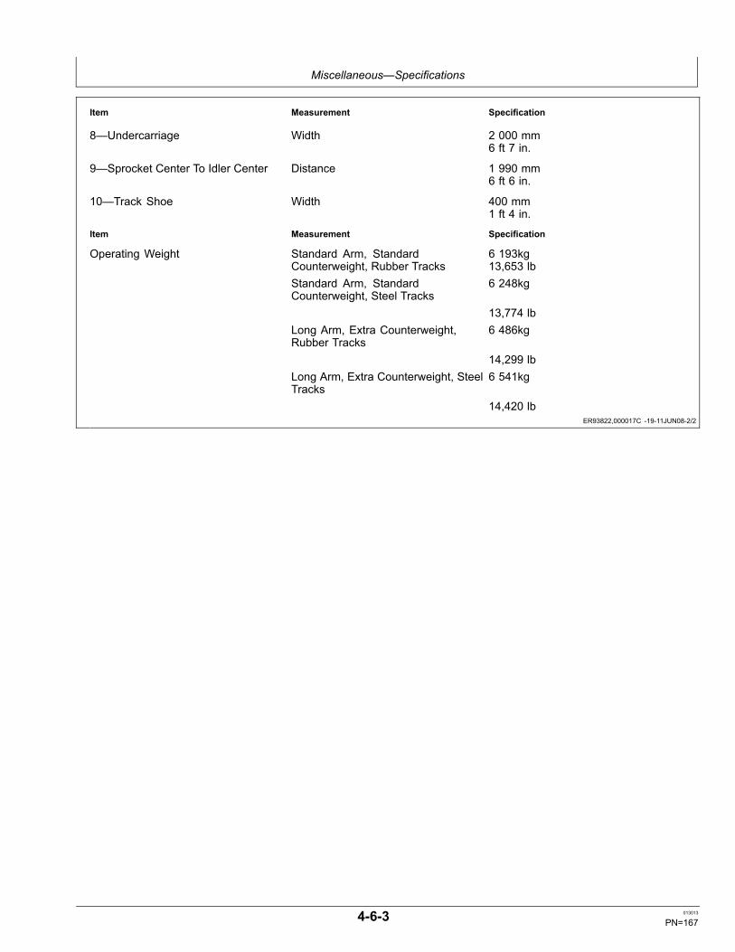
Miscellaneous—Specifications
ER93822,000017C -19-11JUN08-2/2
Item Measurement Specification
8—Undercarriage Width 2 000 mm6 ft 7 in.
9—Sprocket Center To Idler Center Distance 1 990 mm6 ft 6 in.
10—Track Shoe Width 400 mm1 ft 4 in.
Item Measurement Specification
Operating Weight Standard Arm, StandardCounterweight, Rubber Tracks
6 193kg13,653 lb
Standard Arm, StandardCounterweight, Steel Tracks
6 248kg
13,774 lbLong Arm, Extra Counterweight,Rubber Tracks
6 486kg
14,299 lbLong Arm, Extra Counterweight, SteelTracks
6 541kg
14,420 lb
4-6-3 013013
PN=167

Miscellaneous—Specifications
Continued on next page ER93822,000017D -19-11JUN08-1/2
Working Ranges
TX1043799—UN—12JU
N08
1—Maximum Digging Reach2—Maximum Digging Depth3—Maximum Cutting Height4—Maximum Dumping Height
5—Transport Height6—Overall Transport Length7—Minimum Swing Radius8—Blade Bottom Highest
Position (above ground level)
9—Blade Bottom LowestPosition (above ground level)
10— Boom Offset (left)11— Boom Offset (right)
Item Measurement Specification
1—Maximum Digging Reach Distance—Standard Arm 6 230mm20 ft 5 in.
Distance—Long Arm 6 560 mm21 ft 6 in.
2—Maximum Digging Depth Distance—Standard Arm 3 770 mm12 ft 4 in.
Distance—Long Arm 4 120 mm13 ft 6 in.
3—Maximum Cutting Height Distance—Standard Arm 5 960 mm19 ft 7 in.
Distance—Long Arm 6 190 mm20 ft 4 in.
4—Maximum Dumping Height Distance—Standard Arm 4 170 mm13 ft 8 in.
Height—Long Arm 4 400 mm14 ft 5 in.
5—Transport Height—Rubber Track Distance 2 560 mm8 ft 5 in.
6—Transport Length Distance—Standard Arm 5 760 mm18 ft 11 in.
4-6-4 013013
PN=168

Miscellaneous—Specifications
ER93822,000017D -19-11JUN08-2/2
ER93822,000017E -19-02JUN08-1/1
Item Measurement Specification
Distance—Long Arm 5 790 mm19 ft 0 in.
7—Minimum Swing Radius Distance—Standard Arm 2 470 mm8 ft 1 in.
Distance—Long Arm 2 560 mm8 ft 5 in.
8—Blade Bottom Highest Position(above ground level)
Distance 445 mm1 ft 6 in.
9—Blade Bottom Lowest Position(above ground level)
Distance 390 mm1 ft 3 in.
10—Offset Distance To Right Maximum Distance 720 mm2 ft 4 in.
11—Offset Distance To Left Maximum Distance 850 mm2 ft 10 in.
Lift Capacity—Standard 1.50 m (4 ft 11 in.) Arm
Rubber TrackLoad Radius
1.52 m5 ft
3.05 m10 ft
4.57 m15 ft
At MaximumReach
Load PointHeight
Side Front Side Front Side Front Side Front @ft
3.05 m10 ft
851 kg1877 lb
1319 kg*2908 lb*
567 kg1250 lb
1031 kg*2272 lb*
18.8
1.52 m5 ft
794 kg1751 lb
1677 kg*3698 lb*
498 kg1099 lb
1086 kg*2394 lb*
19.7
0 1356 kg2990 lb
2701 kg*5954 lb*
740 kg1631 lb
2012 kg*4436 lb*
527 kg1161 lb
1283 kg*2828 lb*
18.7
—1.52 m—5 ft
3256 kg*7175 lb*
3256 kg*7175 lb*
1375 kg3032 lb
3184 kg*7020 lb*
738 kg1627 lb
1846 kg*4069 lb*
723 kg1594 lb
1497 kg*3301 lb*
15.5
60D Lift Capacity—Standard Arm & Standard Counterweight
Steel TrackLoad Radius
1.52 m5 ft
3.05 m10 ft
4.57 m15 ft
At MaximumReach
Load PointHeight
Side Front Side Front Side Front Side Front @ft
3.05 m10 ft
851 kg1877 lb
1319 kg*2908 lb*
567 kg1250 lb
1031 kg*2272 lb*
18.8
1.52 m5 ft
794 kg1751 lb
1677 kg*3698 lb*
498 kg1099 lb
1086 kg*2394 lb*
19.7
0 1383 kg3050 lb
2701kg*5954 lb*
740 kg1631 lb
2012 kg*4436 lb*
527 kg1161 lb
1283 kg*2828 lb*
18.7
—1.52 m—5 ft
kg*7175 lb*
3256 kg*7175 lb*
kg3032 lb
3184 kg*7020 lb*
738 kg1627 lb
1846 kg*4069 lb*
723 kg1594 lb
1497 kg*3301 lb*
15.5
4-6-5 013013
PN=169

Miscellaneous—Specifications
ER93822,000017F -19-02JUN08-1/1
Lift Capacity—Long 1.85 m (6 ft 1 in.) Arm
Rubber TrackLoad Radius
1.52 m5 ft
3.05 m10 ft
4.57 m15 ft
At MaximumReach
Load PointHeight
Side Front Side Front Side Front Side Front @ft
3.05 m10 ft
975 kg2149 lb
1135 kg*2503 lb*
585 kg1290 lb
855 kg*1884 lb*
19.9
1.52 m5 ft
1707 kg3764 lb
2486 kg5481 lb
909 kg2005 lb
1531 kg*3375 lb*
523 kg1152 lb
897 kg*1978 lb*
20.7
0 1530 kg3372 lb
3539 kg*7802 lb*
843 kg1858 lb
1945 kg*4287 lb*
546 kg1204 lb
1049 kg*2312 lb*
19.9
—1.52 m—5 ft
2669 kg*5884 lb*
3256 kg*7175 lb*
1527 kg3367 lb
3394 kg*7482 lb*
826 kg1821 lb
1941 kg*4279 lb*
705 kg1554 lb
1423 kg*3137 lb*
17.0
—3.05 m—10 ft
1613 kg3556 lb
1931 kg*4257 lb*
60D Lift Capacity—Long Arm & Additional Counterweight
Steel TrackLoad Radius
1.52 m5 ft
3.05 m10 ft
4.57 m15 ft
At MaximumReach
Load PointHeight
Side Front Side Front Side Front Side Front @ft
3.05 m10 ft
991 kg2184 lb
1135 kg*2503 lb*
596 kg1315 lb
1031 kg*2272 lb*
19.9
1.52 m5 ft
1735 kg3824 lb
2486 kg5481 lb
926 kg2041 lb
1531 kg*3375 lb*
80 kg176 lb
1086 kg*2394 lb*
20.7
0 1557 kg3432 lb
3539 kg*7802 lb*
859 kg1893 lb
1945 kg*4287 lb*
557 kg1229 lb
1283 kg*2828 lb*
19.9
—1.52 m—5 ft
2669 kg*5884 lb*
2669 kg*5884 lb*
1554 kg3427 lb
3394 kg*7482 lb*
842 kg1856 lb
1941 kg*4279 lb*
719 kg1585 lb
1497 kg*3301 lb*
17.0
—3.05 m—10 ft
1640 kg3616 lb
1931 kg*4257 lb*
60D Lift Capacity—Long Arm & Additional Counterweight
4-6-6 013013
PN=170

Index
Page
A
Access covers ........................................................... 3-2-3Access doors ............................................................. 3-2-3Acid burns.................................................................. 4-1-5AdjustSeat...................................................................... 2-1-15
AdjustmentEngine valve lash (clearance).............................. 3-10-3Track sag ............................................................... 3-4-6
AirIntake hose ............................................................ 4-1-3
Air cleaner elementClean...................................................................... 3-3-1
Air conditioner............................................................ 2-1-9Air conditioningCondenser ........................................................... 4-1-18Condenser screens.............................................. 4-1-18
Alternator .......................................................3-10-3, 4-1-4Indicator ................................................................. 2-1-4Precaution.............................................................. 4-1-4Voltage indicator .................................................... 2-1-3
Angle blade................................................................ 2-2-6AttachmentsAdding safely ......................................................... 1-3-4Operating safely..................................................... 1-3-4
Auto-idleOperational check................................................ 4-2-12
Auxiliary function lever switch.................................... 2-2-9Auxiliary line selector valve ..................................... 2-2-10Auxiliary pedal ........................................................... 2-2-8Auxiliary power outlet .............................................. 4-1-17
B
Backfill blade operating tips....................................... 2-2-7Backover accidentsAvoiding ................................................................. 1-3-3
BatteriesBoost starting......................................................... 4-1-9
BatteryAcid burns.............................................................. 4-1-5Electrolyte level check ........................................... 4-1-5Explosion ............................................................... 4-1-5Handling, checking, and servicing ......................... 4-1-7Specification........................................................... 4-1-8Terminals................................................................ 4-1-5
Battery chargerUsing...................................................................... 4-1-8
Battery explosionsPrevent................................................................... 1-2-4
Before starting work................................................... 2-2-1Belt tensionFan...............................................................3-5-3, 3-6-3
Blade ......................................................................... 2-2-7Angle...................................................................... 2-2-6Operating ............................................................... 2-2-7
Page
Blade functionOperational check................................................ 4-2-23
Blade pinsLubricate ................................................................ 3-9-4
Bleed hydraulic system............................................ 4-1-17Bolt and screw torque valuesMetric ................................................................... 4-1-16Unified inch .......................................................... 4-1-15
BoomLower with engine stopped .................................. 2-2-12
Bottom pinLubricate ................................................................ 3-8-2
Breaker ...................................................................... 3-2-7BucketRemoval............................................................... 4-1-14Tooth .................................................................... 4-1-13Tooth replacement .....................................3-4-3, 4-1-13
Bucket and link pinsLubricate ......................................................3-5-1, 3-6-1
C
CabDoor release lever................................................ 2-1-15Fresh air filter ......................................................... 4-1-1Recirculating air filter ............................................. 4-1-2
Cab guarding............................................................. 1-2-2Center pinLubricate ................................................................ 3-9-4
Chemical productsHandling................................................................. 1-2-5
CleaningAir conditioning condenser and screens.............. 4-1-18
Clock........................................................................ 2-1-12Control leverPattern conversion................................................. 2-2-5Universal joint ........................................................ 3-9-3
Control pattern operation........................................... 2-2-4Control valve liftOperational check................................................ 4-2-20
Converting track ...................................................... 4-1-21COOL-GARD II test strips ......................................... 3-3-2CoolantAdd coolant extender ............................................. 3-3-2Additional information .......................................... 3-1-10Check..................................................................... 3-3-2Diesel engine ............................................. 3-1-7, 3-11-2Hose..................................................................... 3-11-1John Deere Cool-Gard II Coolant Extender ........... 3-1-8Level recovery tank................................................ 3-4-3Sample................................................................... 3-9-6Supplemental additives.......................................... 3-1-9Test ........................................................................ 3-3-2Testing.................................................................. 3-1-11Warm temperature climates................................... 3-1-9
CoolingSystem drain ........................................................ 3-11-1System, fill............................................................ 3-11-2
Continued on next page
Index-1 013013
PN=1

Index
Page
CoversAccess ................................................................... 3-2-3
Crusher...................................................................... 3-2-7Cycle timesOperational check................................................ 4-2-25
Cylinder ..................................................................... 4-1-1
D
Daily machine check.................................................. 2-2-1Diesel fuel........................................................3-1-1, 3-1-2Sample................................................................... 3-9-6
Diesel fuel, testingTesting Diesel Fuel................................................. 3-1-3
Dig function driftOperational check................................................ 4-2-19
DoorRelease lever ....................................................... 2-1-15
DoorsAccess ................................................................... 3-2-3Engine access........................................................ 3-2-3
Drain and refill capacities35D ........................................................................ 4-6-1
Drain Intervals for Diesel Engine CoolantDiesel Engine Coolant, Drain Intervals .................. 3-1-8
DrivingSlopes.................................................................. 2-2-11
Driving metal pins ...................................................... 1-4-2Dust valveClean...................................................................... 4-1-3Replace.................................................................. 3-9-5
E
E (economy), P (standard) modeOperational check................................................ 4-2-11
ElectricalSystem, troubleshooting ........................................ 4-3-5
Emergency preparation ............................................. 1-2-5EngineCold weather warm-up........................................... 2-2-2Coolant temperature gauge .........................2-1-3, 2-1-4Oil change.............................................................. 3-9-1Oil filter, replace ..................................................... 3-9-1Oil level check........................................................ 3-4-1Speed control knob................................................ 2-1-7Starting................................................................... 2-2-2Troubleshooting ..................................................... 4-3-2Valve lash (clearance) adjustment ....................... 3-10-3
Engine coolant temperatureIndicator .......................................................2-1-3, 2-1-4
Engine oilPressure indicator ........................................2-1-3, 2-1-4Sample................................................................... 3-8-3
Engine preheatOperational check.................................................. 4-2-4
Engine serial number................................................. 4-5-1Engine specifications35D ........................................................................ 4-6-1
Page
Engine speed dialOperational check................................................ 4-2-10
Exhaust fumes........................................................... 1-2-4ExplosionBattery.................................................................... 1-2-4
F
Fan beltCheck and adjust .........................................3-5-3, 3-6-3
FilterCab fresh air .......................................................... 4-1-1Cab recirculating air ............................................... 4-1-2Final fuel, replace................................................... 3-9-4Hydraulic tank replace ........................................... 3-7-1Pilot system, replace............................................ 3-10-2
Fire prevention........................................................... 1-2-4Fluid analysis test kit ................................................. 3-2-8Front joint pinsGrease ................................................................... 3-5-2Lubricate ......................................................3-6-2, 3-9-2
FuelDiesel ...........................................................3-1-1, 3-1-2Gauge ..........................................................2-1-3, 2-1-4Handling and storing.............................................. 3-1-3Level indicator..............................................2-1-3, 2-1-4Tank ....................................................................... 3-2-6Tank inlet screen.................................................... 4-1-1Tank sump drain..................................................... 3-4-2
Fuel gauge and hour meterOperational check.................................................. 4-2-2
Fuel systemPrime...................................................................... 4-1-4
Function lever switchAuxiliary ................................................................. 2-2-9
FunctionsSwitch ..........................................................2-1-5, 2-1-6
FuseColor codes.......................................................... 4-1-11Replacing............................................................. 4-1-11
G
GaugesLocation ................................................................. 2-1-3Locationn of ........................................................... 2-1-4
GreaseExtreme pressure and multipurpose...................... 3-1-7Front joint pins ....................................................... 3-5-2Specification........................................................... 3-1-7
H
Handhold Use............................................................ 1-3-1Hardware torque valuesMetric ................................................................... 4-1-16Unified inch .......................................................... 4-1-15
Continued on next page
Index-2 013013
PN=2

Index
Page
HazardsAvoiding ................................................................. 1-3-2
Heater........................................................................ 2-1-9Heater and air conditioningOperational check................................................ 4-2-26
High-pressure oilsAvoid ...................................................................... 1-2-3
Horn........................................................................... 2-1-7Horn circuitOperational check.................................................. 4-2-1
HoseCoolant................................................................. 3-11-1
Hour meter............................................ 2-1-3, 2-1-4, 3-2-1Hour meter and fuel gaugeOperational check.................................................. 4-2-2
HydraulicBreaker .................................................................. 3-2-7Control shutoff lever............................................... 2-1-8Crusher .................................................................. 3-2-7Oil change............................................................ 3-11-3Oil specification...................................................... 3-1-6Oil tank level check................................................ 3-4-2Sump drain............................................................. 3-8-3System troubleshooting ......................................... 4-3-8Tank filter replace................................................... 3-7-1
Hydraulic oil tank pressurizationOperational check................................................ 4-2-15
Hydraulic systemBleed procedure................................................... 4-1-17
I
IndicatorAlternator output .................................................... 2-1-4Alternator voltage................................................... 2-1-3Auto idle ................................................................. 2-1-4Engine coolant temperature.........................2-1-3, 2-1-4Engine oil pressure ......................................2-1-3, 2-1-4Fast travel mode .................................................... 2-1-4Fuel level......................................................2-1-3, 2-1-4Hour meter ............................................................. 2-1-4Location ................................................................. 2-1-3Location of ............................................................. 2-1-4Pre-heat .......................................................2-1-3, 2-1-4System failure ........................................................ 2-1-4
InjectionNozzle .................................................................... 4-1-1Pump...................................................................... 4-1-1
Inspect machine ........................................................ 1-2-2Installing rubber track .............................................. 4-1-20
J
JDLink...................................................................... 4-1-10Laptop connection................................................ 4-1-10
Page
K
Key switch ................................................................. 2-1-6KnobEngine speed control ............................................. 2-1-7
L
LeverCab door release ................................................. 2-1-15Hydraulic control shutoff ........................................ 2-1-8Left control ............................................................. 2-2-4Pilot control shutoff ................................................ 2-1-8Right control........................................................... 2-2-4Steering.................................................................. 2-2-3
LeversLocation ................................................................. 2-1-1
Lifting....................................................................... 2-2-11Machine ............................................................... 2-2-14
Lifting objectsSpecial care ........................................................... 1-3-4
Light circuitOperational check.................................................. 4-2-5
LubricantAlternative .............................................................. 3-1-4Mixing..................................................................... 3-1-4
LubricateBlade pins .............................................................. 3-9-4Bucket and link pins .....................................3-5-1, 3-6-1Center pin .............................................................. 3-9-4Front joint pins .............................................3-6-2, 3-9-2Pins, bottom and rod.............................................. 3-8-2Swing bearing ........................................................ 3-8-1Swing gear ............................................................. 3-9-3Tilt mechanism....................................................... 3-8-1
M
MachineClean regularly....................................................... 4-1-9Lifting ................................................................... 2-2-14Specifications, 35D ................................................ 4-6-2Towing.................................................................. 2-2-13
Machine inspection.................................................... 1-2-2Machine modificationsAvoid ...................................................................... 1-2-2
Machine movementUnintended............................................................. 1-3-1
Machine tip overAvoiding ................................................................. 1-3-3
MaintenanceMachine position .................................................... 3-2-2Periodic .................................................................. 3-2-9Record keeping...................................................... 3-2-7Schedule and record..................................3-2-9, 3-2-10
Metal pins .................................................................. 1-4-2Metric bolt and screw torque values ........................ 4-1-16Mixing lubricants........................................................ 3-1-4
Continued on next page
Index-3 013013
PN=3

Index
Page
Monitor and gaugesOperational check........................................4-2-3, 4-2-8
Monitor panel...................................................2-1-3, 2-1-4Moving partsSafety..................................................................... 1-2-3Servicing ................................................................ 1-2-3
O
OilChange hydraulic tank ......................................... 3-11-3Engine sample ....................................................... 3-8-3Filter engine ........................................................... 3-9-1Hydraulic level........................................................ 3-4-2Hydraulic sample ................................................... 3-9-6Level engine........................................................... 3-4-1Level travel gear case............................................ 3-8-2Specification hydraulic ........................................... 3-1-6Specification track gearbox.................................... 3-1-6Travel gearbox sample .......................................... 3-9-6Travel gearbox, change ....................................... 3-10-1
Oil coolerClean...................................................................... 3-3-1
OperationClock.................................................................... 2-1-12Radio.................................................................... 2-1-12
Operation qualification............................................... 1-2-1Operational checkAuto-idle............................................................... 4-2-12Blade function ...................................................... 4-2-23Control valve lift ................................................... 4-2-20Cycle times .......................................................... 4-2-25Dig function drift ................................................... 4-2-19E (economny), P (standard) mode....................... 4-2-11Engine preheat....................................................... 4-2-4Engine speed dial ................................................ 4-2-10Fuel gauge and hour meter.................................... 4-2-2Heater and air conditioning.................................. 4-2-26Horn circuit............................................................. 4-2-1Hour meter and fuel gauge .................................... 4-2-2Hydraulic oil tank pressurization .......................... 4-2-15Light circuit............................................................. 4-2-5Monitor and gauges .....................................4-2-3, 4-2-8P (standard), E (economy) mode......................... 4-2-11Pilot control shut-off switch .................................... 4-2-9Pilot controller pattern, ISO excavator pattern ..... 4-2-16Pilot controller pattern, SAE backhoe pattern ...... 4-2-17Power mode......................................................... 4-2-11Swing dynamic brake........................................... 4-2-18Travel alarm ......................................................... 4-2-13Travel lever and pedal operation ........................... 4-2-3Travel speed change ........................................... 4-2-21Travel system tracking ......................................... 4-2-22Washer circuit ........................................................ 4-2-7Wiper circuit, cab ................................................... 4-2-6
Operational checkout................................................. 4-2-1Operator convenience ............................................... 1-1-1Operator stationTilting procedure .................................................... 3-2-5
Page
Operator's station ...................................................... 2-1-1
P
P (standard), E (economy) modeOperational check................................................ 4-2-11
PanelSwitch ..........................................................2-1-5, 2-1-6
PanelsLocation ................................................................. 2-1-1
Parking machine...................................................... 2-2-12Pattern conversionControl levers......................................................... 2-2-5
PedalAuxiliary ................................................................. 2-2-8Location ................................................................. 2-1-1Steering.................................................................. 2-2-3
Periodic maintenance chart ....................................... 3-2-1PilotControl shutoff lever............................................... 2-1-8System oil filter, replace....................................... 3-10-2
Pilot control shut-off switchOperational check.................................................. 4-2-9
Pilot control shutoff lever ........................................... 1-3-1Pilot controller pattern ISO excavator patternOperational check................................................ 4-2-16
Pilot controller pattern, SAE backhoe patternOperational check................................................ 4-2-17
Power modeOperational check................................................ 4-2-11
Pre-heatIndicator .......................................................2-1-3, 2-1-4
Pre-start inspection.................................................... 2-2-1Primary elementReplace.................................................................. 3-9-5
PrimeFuel system............................................................ 4-1-4
Product identification number .................................... 4-5-1Protective equipment................................................. 1-2-2PumpService................................................................... 4-1-1
Q
Quick couplerBucket install........................................................ 4-1-19
R
RadiatorDrain .................................................................... 3-11-1
Radiator coreClean...................................................................... 3-3-1
Radio ....................................................................... 2-1-12Recovery tankCoolant level .......................................................... 3-4-3
Removing rubber track ............................................ 4-1-20Riding machine.......................................................... 1-3-2
Continued on next page
Index-4 013013
PN=4

Index
Page
Rod pinLubricate ................................................................ 3-8-2
Rubber trackCheck sag.............................................................. 3-4-4Install and remove................................................ 4-1-20
Rubber track care.................................................... 4-1-20
S
SafetyOperator's seat ...................................................... 1-3-1
Safety equipment....................................................... 1-2-2Safety features .......................................................... 1-1-1Safety informationRecognizing ........................................................... 1-2-1
Safety instructions ..................................................... 1-2-1Safety symbols .......................................................... 1-2-1Safety, Avoid High-Pressure FluidsAvoid High-Pressure Fluids ................................... 1-2-3
SeatAdjust ................................................................... 2-1-15
Seat beltUse and maintenance..................................1-3-1, 3-4-6
Secondary element (if equipped)Replace.................................................................. 3-9-5
Secondary exitWindow ................................................................ 2-1-14
Secondary exit tool .................................................. 2-1-13Serial numberEngine.................................................................... 4-5-1
Service intervals ........................................................ 3-2-9Servicing machine safely........................................... 1-4-1SlopesDriving up............................................................. 2-2-11
SpecificationCooling system .................................................... 3-11-2Grease ................................................................... 3-1-7Hydraulic oil ........................................................... 3-1-6Travel gearbox oil .................................................. 3-1-6
Starter motor..................................................3-10-3, 4-1-4Steel trackCheck sag.............................................................. 3-4-5
SteeringMachine ................................................................. 2-2-3
Steps Use.................................................................. 1-3-1Stopper ...................................................................... 3-2-3StorageMachine ................................................................. 4-4-1Monthly .................................................................. 4-4-1
Storing fuel ................................................................ 3-1-3SwingArea cleaning....................................................... 2-2-10
Swing bearingLubricate ................................................................ 3-8-1
Swing dynamic brakeOperational check................................................ 4-2-18
Swing gearLubricate ................................................................ 3-9-3
Page
SwitchAuto-idle................................................................. 2-1-6Auxiliary flow control ....................................2-1-5, 2-1-6Horn ....................................................................... 2-1-7Key......................................................................... 2-1-6Power mode.................................................2-1-5, 2-1-6Travel alarm cancel......................................2-1-5, 2-1-8Travel mode .................................................2-1-5, 2-1-6Windshield wiper/washer .............................2-1-5, 2-1-6Work light .....................................................2-1-5, 2-1-6
Synthetic lubricants ................................................... 3-1-4
T
TankAccess ................................................................... 3-2-3Fuel ........................................................................ 3-2-6
Tilt MechanismLubricate ................................................................ 3-8-1
Tip overAvoiding ................................................................. 1-3-3
ToolSecondary exit ..................................................... 2-1-13
Torque chartsMetric ................................................................... 4-1-16Unified inch .......................................................... 4-1-15
TowingMachine ............................................................... 2-2-13
TrackConversion........................................................... 4-1-21Sag adjustment ...................................................... 3-4-6Sag check ....................................................3-4-4, 3-4-5Sag, general information...................................... 4-1-14Shoe cap screw hardware ................................... 4-1-14
Track careRubber ................................................................. 4-1-20
TransportLoading and unloading machine.......................... 2-2-13
TravelGear case oil level check....................................... 3-8-2Gearbox oil change.............................................. 3-10-1Gearbox oil specification........................................ 3-1-6
Travel alarm............................................................... 2-1-8Cancel switch......................................................... 2-1-8Operational check................................................ 4-2-13
Travel lever and pedal operationOperational check.................................................. 4-2-3
Travel speed changeOperational check................................................ 4-2-21
Travel system trackingOperational check................................................ 4-2-22
Trip meter ................................................................ 2-1-11TroubleshootingElectrical system.................................................... 4-3-5Engine.................................................................... 4-3-2Hydraulic system.................................................... 4-3-8
Continued on next page
Index-5 013013
PN=5

Index
Page
U
Unified inch bolt and screw torque values ............... 4-1-15UsingBattery charger ...................................................... 4-1-8
V
ValveControl ................................................................... 4-1-1
W
Washer circuitOperational check.................................................. 4-2-7
Washer fluidCheck..................................................................... 3-2-6
Page
Waste disposal .......................................................... 1-2-5Water separatorDrain ...................................................................... 3-4-3
Water separator elementReplace.................................................................. 4-1-4
Welding...................................................................... 4-1-9Welding repairs.......................................................... 1-4-2WindowCab ...................................................................... 2-1-15Front..................................................................... 2-1-14Lower front ........................................................... 2-1-14Secondary exit ..................................................... 2-1-14
Wiper circuit, cabOperational check.................................................. 4-2-6
Work site hazardsAvoid ...................................................................... 1-3-2
Working ranges35D ........................................................................ 4-6-4
Index-6 013013
PN=6

Index
Index-7 013013
PN=7

Index
Index-8 013013
PN=8