MAGAZINE For owners and operators of Twin Commander Aircraft
Upload
forklift-systems-incorporatedCategory
view
215download
0
7/28/2019 606895 Commander Gas Owners Manual 2010
http://slidepdf.com/reader/full/606895-commander-gas-owners-manual-2010 1/72
A Textron Company
GASOLINE POWERED UTILITY VEHICLES
ISSUED OCTOBER 2007 REVISED MARCH 2010
OWNER’S MANUALAND SERVICE GUIDE
606895

7/28/2019 606895 Commander Gas Owners Manual 2010
http://slidepdf.com/reader/full/606895-commander-gas-owners-manual-2010 2/72
SAFETY
(NOTES, CAUTIONS AND WARNINGS CONTINUED ON INSIDE OF BACK COVER)
For any questions on material contained in this manual, contact an authorized representative for clarification.
Read and understand all labels located on the vehicle. Always replace any damaged or missing labels.
On steep hills it is possible for vehicles to coast at greater than normal speeds encountered on a flat surface. To pre-
vent loss of vehicle control and possible serious injury, speeds should be limited to no more than the maximum speedon level ground. See GENERAL SPECIFICATIONS. Limit speed by applying the service brake.
Catastrophic damage to the drivetrain components due to excessive speed may result from driving the vehicle abovespecified speed. Damage caused by excessive speed may cause a loss of vehicle control, is costly, is consideredabuse and will not be covered under warranty.
For towing/transporting vehicle, refer to “TRANSPORTING VEHICLE”.
Signs similar to the ones illustrated should be used to warn of situations that could result in an unsafe condition.
Be sure that this manual remains as part of the permanent service record should the vehicle be sold. Throughout this
guide NOTE, CAUTION and WARNING will be used.
Observe these NOTES, CAUTIONS and WARNINGS; be aware that servicing a vehicle requires mechanical skill and
a regard for conditions that could be hazardous. Improper service or repair may damage the vehicle or render it unsafe.
WASH HANDS
AFTER HANDLING!
Battery posts,terminals and related
accessories containlead and lead compounds,
chemicals knownto cause cancer andreproductive harm.
BATTERY WARNING
WASH HANDS
AFTER HANDLING!WARNING: Battery posts, terminals and relatedaccessories contain lead and lead compounds,
chemicals known to cause cancer and reproductive harm.
BATTERIES
CONTAIN LEAD AND RELATED PARTS
!
< 14˚ 25%
DO NOT
DRIVE ACROSS
SLOPES IN
EXCESS OF 14˚
A NOTE indicates a condition that should be observed.
A CAUTION indicates a condition that may result in damage to the vehicle.
A WARNING indicates a hazardous condition that could result in severe injury or death.
Engine exhaust from this product contains chemicals known, in certain quantities, to cause cancer, birth defects, or other reproduc- tive harm.
The exhaust emissions of this vehicles’ engine complies with
regulations set forth by the Environmental Protection Agency
(EPA) of the United States of America (USA) at time of manu-
facture. Significant fines could result from modifications or tam-
pering with the engine, fuel, ignition or air intake systems.
Battery posts, terminals and related accesso- ries contain lead and lead compounds. Wash
hands after handling.
This spark ignition system meets all requirements of the Cana-
dian Interference-Causing Equipment Regulations.
Ce système d'allumage par étincelle de véhicule respecte
toutes les exigences du Règlement sur le matériel brouilleu
du Canada.

7/28/2019 606895 Commander Gas Owners Manual 2010
http://slidepdf.com/reader/full/606895-commander-gas-owners-manual-2010 3/72
PageOwner’s Manual and Service Guide
OWNER’S MANUAL
AND SERVICE GUIDE
GASOLINE POWERED
UTILITY VEHICLES
COMMANDER™ (280, 280CARB)
COMMANDER™ (2200, 2200CARB)
Starting Model Year 2008
The E-Z-GO Division of Textron Inc. reserves the right to incorporate engineering and design changes to products in this Manual, without obligation toinclude these changes on units leased/sold previously.
The information contained in this Manual may be revised periodically by the E-Z-GO Division, and therefore is subject to change without notice.
The E-Z-GO Division DISCLAIMS LIABLITY FOR ERRORS IN THIS MANUAL, and the E-Z-GO Division SPECIFICALLY DISCLAIMS LIABILITY FORINCIDENTAL AND CONSEQUENTIAL DAMAGES resulting from the use of the information and materials in this Manual.
These are the orginal instructions as defined by 2006/42/EC.
TO CONTACT US
NORTH AMERICA:
TECHNICAL ASSISTANCE & WARRANTY PHONE: 1-800-774-3946, FAX: 1-800-448-8124
SERVICE PARTS PHONE: 1-888-GET-EZGO (1-888-438-3946), FAX: 1-800-752-6175
INTERNATIONAL: PHONE: 001-706-798-4311, FAX: 001-706-771-4609
E-Z-GO DIVISION OF TEXTRON, INC., 1451 MARVIN GRIFFIN ROAD, AUGUSTA, GEORGIA USA 30906-3852

7/28/2019 606895 Commander Gas Owners Manual 2010
http://slidepdf.com/reader/full/606895-commander-gas-owners-manual-2010 4/72
Page ii Owner’s Manual and Service Guide
GENERAL INFORMATION
This vehicle has been designed and manufactured in the United States of America (USA) as
a ‘World Vehicle’. The Standards and Specifications listed in the following text originate in
the USA unless otherwise indicated.
The use of non Original Equipment Manufacturer (OEM) approved parts may void the
warranty.
Overfilling battery may void the warranty.
Tampering with or adjusting the governor to permit vehicle to operate at above factory
specifications will void the vehicle warranty.
When servicing engines, all adjustments and replacement components must be per original
vehicle specifications in order to maintain the United States of America Federal and Stateemission certification applicable at the time of manufacture.
BATTERY PROLONGED STORAGE
All batteries will self discharge over time. The rate of self discharge varies depending on the
ambient temperature and the age and condition of the batteries.
A fully charged battery will not freeze in winter temperatures unless the temperature fallsbelow -75°F (-60°C).

7/28/2019 606895 Commander Gas Owners Manual 2010
http://slidepdf.com/reader/full/606895-commander-gas-owners-manual-2010 5/72
Page Owner’s Manual and Service Guide
TABLE OF CONTENTS
SAFETY ................................................................................................................ inside covers
GENERAL INFORMATION ....................................................................................................... ii
SAFETY INFORMATION ........................................................................................................... v
BEFORE INITIAL USE .............................................................................................................. 1Fig. 1 Initial Service Chart .......................................................................................................1
CONTROLS AND INDICATORS ............................................................................................... 1KEY/LIGHT SWITCH ...........................................................................................................................................2
Fig. 2 Key/Light Switch ...........................................................................................................2
LOW OIL PRESSURE INDICATOR LIGHT .........................................................................................................2
FUEL GAUGE ......................................................................................................................................................2
DIRECTION SELECTOR .....................................................................................................................................2
Fig. 3 Direction Selector .........................................................................................................2
CHOKE ................................................................................................................................................................2
Fig. 4 Choke ...........................................................................................................................2
ACCELERATOR PEDAL .....................................................................................................................................3
Fig. 5 Accelerator, Brake and Horn Controls .......................... ............... .................. ............... 3
COMBINATION BRAKE AND PARK BRAKE PEDAL .........................................................................................3
OPTIONAL FRONT DISC BRAKES.....................................................................................................................3HORN .............. ................. ............... ................ ............... ................. ............... .................. ................. ................. ..3
PLASTIC LOAD BED ................................................................................................................ 3MANUAL LIFT BED OPERATION .......................................................................................................................4
Fig. 6 Manual Bed Latch .........................................................................................................4
Fig. 7 Gas Strut........................................................................................................................4
TAIL GATE OPERATION.............. ................ ............... ............... ................ ............... ............... ................... ........ 4
ELECTRIC LIFT BED OPERATION.....................................................................................................................4
Fig. 8 Electric Lift Switch..........................................................................................................4
OPERATING THE VEHICLE ..................................................................................................... 5RUN-IN ................................................................................................................................................................5
Fig. 9 Check Oil Level on Dipstick ..........................................................................................5
Fig. 10 Clean Entire Dipstick ............... ............... ............... .................. ............... ............... ........ 6
COLD STARTING ................................................................................................................................................6
STARTING AND DRIVING ..................................................................................................................................6STARTING THE VEHICLE ON A HILL ................................................................................................................6
COASTING ..........................................................................................................................................................6
FUEL ....................................................................................................................................................................7
Fig. 11 Fueling ..........................................................................................................................7
BATTERY ............................................................................................................................................................7
LABELS AND PICTOGRAMS .............. ............... ................ ............... ............... ............... .................... ............... 7
SUN TOP AND WINDSHIELD .............................................................................................................................7
12 VOLT POWER OUTLET..................................................................................................................................8
Fig. 12 12 Volt Power Outlet......................................................................................................8
TOWING A TRAILER ................ ............... ................. ............... ................ ............... ................. ............... ............ 8
VEHICLE CLEANING AND CARE ............................................................................................ 8VEHICLE CLEANING ..........................................................................................................................................8
REPAIR ..................................................................................................................................... 9LIFTING THE VEHICLE ................. ................ ............... ............... ................. ................ ................. ............... ......9
Fig. 13 Lifting the Vehicle ............... ............... .................. ............... ............... ................. .......... 9
WHEELS AND TIRES ............... ............... ............... ............... .................. ............... ............... ................. ............ 9
WHEEL INSTALLATION ....................................................................................................................................10
Fig. 14 Wheel Installation ..................... ............... ............. ................ ............... ............... ........10
LIGHT BULB REPLACEMENT ..........................................................................................................................10
Fig. 15 Headlight and Turn Signal Bulb Replacement ....................... ................. ................. ..11
Fig. 16 Tail and Brake Light Bulb Replacement ......................................................................11
FUSE REPLACEMENT .....................................................................................................................................11
VEHICLE WITH A DISCHARGED BATTERY ................. ............... ............... ................ ............... ..................... 11
TRANSPORTING VEHICLE .................................................................................................... 11
7/28/2019 606895 Commander Gas Owners Manual 2010
http://slidepdf.com/reader/full/606895-commander-gas-owners-manual-2010 6/72
Page iv Owner’s Manual and Service Guide
TABLE OF CONTENTS
TOWING ............................................................................................................................................................11
NEUTRAL LOCK ...............................................................................................................................................11
Fig. 17 Neutral Lock ................ ............... ............... ............... .................. ............... ..................12
HAULING ...........................................................................................................................................................12
SERVICE AND MAINTENANCE ..............................................................................................13SERIAL NUMBER PLATE AND LOCATION ...... .................. ............... ................. ............... .................. ............13
Fig. 18 Serial Number Plate & Location............... ............... ................ ............... ............... .......14
PERIODIC SERVICE SCHEDULE ..... ............... .................. ............... ............... ................. .................. ............15
Fig. 19 Periodic Service Schedule .................... ................. ................ ............... ............... .......15
TIRE INSPECTION ............................................................................................................................................16
FOUR CYCLE ENGINE.............................................................................................................17ENGINE SPECIFICATIONS ............... ................ ............... ................. ............... ................ ................. ................17
ENGINE DESCRIPTION.....................................................................................................................................17
CHECKING OIL LEVEL.................. ................ ............... ............... ................. ................ ............... ............... .......17
Fig. 20 Clean Entire Dipstick........... ............... ................ ............... ............... ................ ............17
Fig. 21 Check Oil Level on Dipstick ................. ................ ............... ................. ............... .........17
CHANGING THE OIL..........................................................................................................................................17
Fig. 22 Oil Viscosity Chart........ ................. ............... ............... ................. ................ ................18
Fig. 23 Cleaning Top of Engine .................. ............... ................. ................. ................ ............18 Fig. 24 Remove Oil Filter ................ ............... .................. ............... ................. ............... .........18
Fig. 25 Inspect Oil Filter .............. ................ ............... ................. ............... .................. ............18
Fig. 26 Oil Drain Plug ................ ................ ............... ................. ............... ................ ................19
Fig. 27 Add Engine Oil .............. ................ ............... ............... ................ ............... ................. .19
Fig. 28 Check Belt Tension with Guage......... .................. ............... ................. ................. .......19
STARTER/GENERATOR BELT TENSION ........................................................................................................19
Fig. 29 Check Belt Tension Manually................. ................ ............... ............... ............... .........20
Fig. 30 Adjust Belt Tension ............... ............... .................. ............... ............... ................. .......20
ADJUSTING THE BELT .....................................................................................................................................20
BATTERY CLEANING................. ............... ................. ............... ................ ................. ............... ............... .........20
Fig. 31 Preparing Acid Neutralizing Solution.............. ................. ............... .................. ............21
Fig. 32 Typical Brake Performance Test........ ................ ............... ............... ................ ............21
BRAKES .............................................................................................................................................................21
PERIODIC BRAKE TEST FOR MECHANICAL BRAKES ..................................................................................22
AIR INTAKE AND COOLING FINS.....................................................................................................................22
Fig. 33 Cleaning Cooling System with Air ................ ............... ................. .................. ..............22
REAR AXLE........................................................................................................................................................22
CHECKING THE LUBRICANT LEVEL ............... ............... ............... ............... ................ ............... ....................22
Fig. 34 Add, Check and Drain Rear Axle Lubricant .............. .................. ............... ............... ...23
AIR CLEANER INSPECTION AND REPLACEMENT ........................................................................................23
Fig. 35 Air Cleaner ................. ............... ............... ............... .................. ............... ............... .....23
LUBRICATION....................................................................................................................................................23
SPARK PLUGS...................................................................................................................................................23
Fig. 36 Lubrication Points ............. ................ ............... ............... ............... ................ ..............24
Fig. 37 Gapping the Spark Plug ................ ............... ................. ............... ................ ............... .24
PROLONGED STORAGE ..................................................................................................................................24
CAPACITIES AND REPLACEMENT PARTS.............. ............... ................ ............... ............... ............... ...........25
Fig. 38 Capacities and Replacement Parts... ................. ............... ............... ................ ............25
HARDWARE.......................................................................................................................................................25
Fig. 39 Torque Specifications and Bolt Grades................... ................ ................. ............... .....26
GENERAL SPECIFICATIONS ..................................................................................................29Fig. 40 Vehicle Dimensions................... ................. ............... ................ ............... ................. ...32
Fig. 41 Vehicle Incline Specifications & Turning Clearance Diameter ................. ............... .....33
LABELS AND PICTOGRAMS ..................................................................................Appendix A
VEHICLE WARRANTIES ..........................................................................................Appendix BCALIFORNIA EMISSION CONTROL WARRANTY STATEMENT...................................................................B-3
FEDERAL EMISSION COMPONENT DEFECT WARRANTY ............... ............... ................. ................ .......... B-5
DECLARATION OF CONFORMITY..........................................................................Appendix C

7/28/2019 606895 Commander Gas Owners Manual 2010
http://slidepdf.com/reader/full/606895-commander-gas-owners-manual-2010 7/72
Owner’s Manual and Service Guide Page
SAFETY INFORMATION
SAFETY INFORMATION
This manual has been designed to assist in maintaining the vehicle in accordance with procedures developed by the
manufacturer. Adherence to these procedures and troubleshooting tips will ensure the best possible service from the
product. To reduce the chance of personal injury or property damage, the following must be carefully observed:
Certain replacement parts can be used independently and/or in combination with other accessories to modify an E-ZGO-manufactured vehicle to permit the vehicle to operate at or in excess of 20mph. When an E-Z-GO-manufacturedvehicle is modified in any way by the Distributor, Dealer or customer to operate at or in excess of 20mph, UNDER FED
ERAL LAW the modified product will be a Low Speed Vehicle (LSV) subject to the strictures and requirements of Fed-eral Motor Vehicle Safety Standard 571.500. In these instances, pursuant to Federal law the Distributor or Deale
MUST equip the product with headlights, rear lights, turn signals, seat belts, top, horn and all other modifications forLSV’s mandated in FMVSS 571.500, and affix a Vehicle Identification Number to the product in accordance with therequirements of FMVSS 571.565. Pursuant to FMVSS 571.500, and in accordance with the State laws applicable in the
places of sale and use of the product, the Distributor, Dealer or customer modifying the vehicle also will be the FinalVehicle Manufacturer for the LSV, and required to title or register the vehicle as mandated by State law.
E-Z-GO will NOT approve Distributor, Dealer or customer modifications converting E-Z-GO products into LSV’s.
The Company, in addition, recommends that all E-Z-GO products sold as personal transportation vehicles BE OPER-ATED ONLY BY PERSONS WITH VALID DRIVERS LICENSES, AND IN ACCORDANCE WITH APPLICABLE STATE
REQUIREMENTS. This restriction is important to the SAFE USE AND OPERATION of the product. On behalf of E-Z-GO, I am directing that E-Z-GO Branch personnel, Distributors and Dealers advise all customers to adhere to this
SAFETY RESTRICTION, in connection with the use of all products, new and used, the Distributor or Dealer has rea-son to believe may be operated in personal transportation applications.
Information on FMVSS 571.500 can be obtained at Title 49 of the Code of Federal Regulations, section 571.500, or
through the Internet at the website for the U.S. Department of Transportation - at Dockets and Regulation, then to Title49 of the Code of Federal Regulations (Transportation).
GENERAL
Many vehicles are used for a variety of tasks beyond the original intended use of the vehicle; therefore, it is impossible
to anticipate and warn against every possible combination of circumstances that may occur. No warnings can take theplace of good common sense and prudent driving practices.
Good common sense and prudent driving practices do more to prevent accidents and injury than all of the warnings
and instructions combined. The manufacturer strongly suggests that all users and maintenance personnel read thisentire manual paying particular attention to the CAUTIONS and WARNINGS contained therein.
If you have any questions regarding this vehicle, contact your closest representative or write to the address on the backcover of this publication, Attention: Product Service Department.
The manufacturer reserves the right to make design changes without obligation to make these changes on units previ-ously sold and the information contained in this manual is subject to change without notice.
The manufacturer is not liable for errors in this manual or for incidental or consequential damages that result from the
use of the material in this manual.

7/28/2019 606895 Commander Gas Owners Manual 2010
http://slidepdf.com/reader/full/606895-commander-gas-owners-manual-2010 8/72
Owner’s Manual and Service GuidePage vi
SAFETY I NFORMATION
This vehicle conforms to the current applicable standard(s) for safety and performance requirements.
These vehicles are designed and manufactured for off-road use. They do not conform to Federal Motor Vehicle Safety
Standards of the United States of America (USA) and are not equipped for operation on public streets. Some commu-nities may permit these vehicles to be operated on their streets on a limited basis and in accordance with local ordi-
nances.
Refer to GENERAL SPECIFICATIONS for vehicle seating capacity.
Never modify the vehicle in any way that will alter the weight distribution of the vehicle, decrease its stabilityor increase the speed beyond the factory specification. Such modifications can cause serious personal injury
or death. Modifications that increase the speed and/or weight of the vehicle will extend the stopping distance and mayreduce the stability of the vehicle. Do not make any such modifications or changes. The manufacturer prohibits and
disclaims responsibility for any such modifications or any other alteration which would adversely affect the safety of thevehicle.
Vehicles that are capable of higher speeds must limit their speed to no more than the speed of other vehicles whenused in a golf course environment. Additionally, speed should be further moderated by the environmental conditions,
terrain and common sense.
Operation of the vehicle is limited to persons above the height of 59 in. (150 cm)
GENERAL OPERATION
Always:
• Use the vehicle in a responsible manner and maintain the vehicle in safe operating condition.
• Read and observe all warnings and operation instruction labels affixed to the vehicle.
• Follow all safety rules established in the area where the vehicle is being operated.
• Leave the vehicle when there is a risk of lightning.
• Reduce speed to compensate for poor terrain or conditions.
• Apply service brake to control speed on steep grades.
• Maintain adequate distance between vehicles.
• Reduce speed in wet areas.
• Use extreme caution when approaching sharp or blind turns.
• Use extreme caution when driving over loose terrain.
• Use extreme caution in areas where pedestrians are present.
MAINTENANCE
Always:
• Maintain the vehicle in accordance with the manufacturer’s periodic service schedule.
• Ensure that repairs are performed by those that are trained and qualified to do so.
• Follow the manufacturer’s maintenance procedures for the vehicle. Be sure to disable the vehicle before performing
any maintenance. Disabling includes removing the key from the key switch and removal of a battery wire.

7/28/2019 606895 Commander Gas Owners Manual 2010
http://slidepdf.com/reader/full/606895-commander-gas-owners-manual-2010 9/72
Owner’s Manual and Service Guide Page v
SAFETY INFORMATION
• Insulate any tools used within the battery area in order to prevent sparks or battery explosion caused by shorting thebattery terminals or associated wiring. Remove the battery or cover exposed terminals with an insulating material.
• Use specified replacement parts. Never use replacement parts of lesser quality.
• Use recommended tools.
• Determine that tools and procedures not specifically recommended by the manufacturer will not compromise the
safety of personnel nor jeopardize the safe operation of the vehicle.
• Support the vehicle using wheel chocks and jack stands. Never get under a vehicle that is supported by a jack. Lif
the vehicle in accordance with the manufacturer’s instructions.
• Empty the fuel tank or plug fuel hoses to prevent fuel leakage.
• Maintain the vehicle in an area away from exposed flame or persons who are smoking.
• Be aware that a vehicle that is not performing as designed is a potential hazard and must not be operated.
• Test drive the vehicle after any repairs or maintenance. All tests must be conducted in a safe area that is free of both
vehicular and pedestrian traffic.
• Replace damaged or missing warning, caution or information labels.
• Keep complete records of the maintenance history of the vehicle.
The manufacturer cannot anticipate all situations, therefore people attempting to maintain or repair the vehicle must
have the skill and experience to recognize and protect themselves from potential situations that could result in severepersonal injury or death and damage to the vehicle. Use extreme caution and, if unsure as to the potential for injury,refer the repair or maintenance to a qualified mechanic.
VENTILATION
Always store gasoline vehicles in a well ventilated area. Ventilation prevents gasoline fumes from accumulating.
Never fuel a vehicle in an area that is subject to flame or spark. Pay particular attention to natural gas or propane wateheaters and furnaces.
Never work around or operate a vehicle in an environment that does not ventilate exhaust gases from the area. Carbon
monoxide is a dangerous gas that can cause unconsciousness and is potentially lethal.

7/28/2019 606895 Commander Gas Owners Manual 2010
http://slidepdf.com/reader/full/606895-commander-gas-owners-manual-2010 10/72
Owner’s Manual and Service GuidePage viii
SAFETY I NFORMATION
NOTES:

7/28/2019 606895 Commander Gas Owners Manual 2010
http://slidepdf.com/reader/full/606895-commander-gas-owners-manual-2010 11/72
Owner’s Manual and Service Guide Page i
SAFETY INFORMATION
The following text is pr ovided as recommended by part II of ANSI/ITSDF B56.8 - 2005. The manufacturer strongly
endorses the contents of this specification.
6 GENERAL SAFETY PRACTICES6.1 Introduction
6.1.1 Like other machines, carriers can cause injury if improperly used or maintained. Part II contains broad safety
practices applicable to carrier operation. Before operation, the user shall establish such additional specific safety prac-
tices as may reasonably be required for safe operation.
6.1.2 Premise review — The user shall periodically review their premises, and as conditions warrant, identify areas
where carriers should not be operated and to identify possible hazards such as the following examples:
a) Steep Grade — In areas where steep grades exist, carrier operation should be restricted to the designated vehi-
cle’s pathways where possible, and shall be identified with a suitable warning giving the following information
“Warning, steep grade.” b) Wet Areas — Wet areas could cause a carrier to lose traction and could affect steering, stability and braking.
c) Sharp Turns, Blind Spots, Bridge Approaches — Sharp turns, blind spots, bridge approaches, and other poten-tially hazardous areas shall be identified with a suitable warning to the operator of the nature of the hazard and
stating the proper precautions to be taken to avoid the hazard.
d) Loose Terrain — Loose terrain could cause a carrier to lose traction and c ould affect steering, stability, and
braking.
6.2 Operation
Experience has shown that carriers, which comply with the provisions, stated in paragraph 9 .3.9 are stable when
properly operated and when operated in accordance with specific safety rules and practices established to meet actua
operating terrain and conditions. However, improper operation, faulty maintenance, or poor housekeeping may contrib-
ute to a condition of instability and defeat the purpose of the standard. Some of the conditions which may affect stability
are failure of the user to follow safety practices; also, ground and floor conditions, grade, speed, loading, the operation
of the carrier with improper loads, battery weight, dynamic and static forces, and the judgment exercised by the carrieroperator.
a) The user shall train carrier operators to adhere strictly to the operating instructions stated in this Standard.
b) The user shall survey specific operating conditions and environment, and establish and train carrier operators to
comply with additional, specific safety practices.
6.3 Nameplates, Markings, Capacity, and Modifications
6.3.1 The user shall maintain in a legible condition all nameplates, warnings, and instructions, which are supplied by
the manufacturer.
6.3.2 Except as provided in 6.3.4, no modifications or alterations to a carrier, which may affect the capacity, stability,
or safe operation of the carrier, shall be made without the prior written approval of the original carrier manufacturer or a
successor thereof. When the carrier manufacturer or its successor approves a modification or alteration, appropriate
changes shall be made to capacity plates, decals, tags, and operation and maintenance manuals
6.3.3 As required under paragraphs 6.3.1 or 6.3.2, the manufacturer shall be contacted to secure new nameplates
warnings, or instructions, which shall then be affixed in their proper place on the carrier.
6.3.4 In the event that the carrier manufacturer is no longer in business and there is no successor in interest to the
business, the user may arrange for a modific ation or altera tion to a carrier, provided however, the controlling p arty
shall:
(1) Arrange for the modification or alteration to be designed, tested, and implemented by an engineer(s) expert in
carrier(s) and their safety;

7/28/2019 606895 Commander Gas Owners Manual 2010
http://slidepdf.com/reader/full/606895-commander-gas-owners-manual-2010 12/72
Owner’s Manual and Service GuidePage x
SAFETY INFORMATION
(2) Maintain a permanent record of the design, test(s), and implementation of the modification or alteration;
(3) Make appropriate changes to the capacity plate(s), decals, tags, and operation and maintenance manuals;
(4) Affix a permanent and readily visible label on the carrier stating the manner in which the carrier has been mod-
ified or altered together with the date of the modification or alteration, and the name of the organization that
accomplished the tasks.
6.4 Fuel Handling and Storage
6.4.1 The user shall supervise the storage and handling of liquid fuels (when used) to be certain that it is in accor-
dance with ANSI/NFPA 505 and ANSI/NFPA 30 or as required by local ordinance.
6.4.2 Storage and handing of liquefied petroleum gas fuels shall be in accordance with ANSI/NFPA 505 and ANSI/
NFPA 58 or as required by local ordinance. If such storage or handling is not in compliance with these standards, the
user shall prevent the carrier from being used until such storage and handling is in compliance with these standards.
6.43 Prevent fire and explosion caused by static electric discharge. Use only non-metal, portable fuel containers
approved by the Underwriter’s Laboratory (U.L.) or the American Society for Testing & Materials (ASTM). If using a fun-
nel, make sure it is plastic and has no screen or filter.
Static electric discharge can ignite gasoline vapors in an ungrounded fuel container. Remove the fuel container fromthe bed of a carrier or the trunk of a car ban place on the ground away from the carrier before fi lling. Keep nozzle in
contact with container opening while filling. When practical, remove equipment from trailers or truck beds and re -fuel
them on the ground. If this is not possible, use a portable, plastic fuel container to refuel equipment on a truck bed or
trailer.
6.5 Changing and Charging Storage Batteries for Electric Personnel and Burden Carriers
6.5.1 The user shall require battery changing and charging facilities and procedures to be in accordance with ANSI/
NFPA 505 or as required by local ordinance.
6.5.2 The user shall periodically inspect fa cilities and review proc edures to be certain that ANSI/NFPA 505 or as
required by local ordinance, are strictly complied with, and shall familiarize carrier operators with it.
6.5.3 Maintenance and storage areas for carriers shall be properly ventilated to avoid fire hazards in accordance
with applicable fire codes and ordinances.
Ventilation for internal combustion engine powered carriers shall be provided to remove flammable vapors (gases),
fumes and other flammable materials. Consult applicable fire codes for specific levels of ventilation.
Ventilation for electric powered carriers shall be provided to remove the accumulation of flammable hydrogen gas
emitted during the battery charging process. The amount of hydrogen gas emitted depends upon a number of factors
such as the condition of the batteries, the output rate of the battery charger and the amount of time the batteries are on
charge. Because of the highly volatile nature of hydrogen gas and its propensity to accumulate in pockets, a minimum
number of air changes per hour is required during charging.
Consult applicable fire and safety codes for the specific ventilation levels required as well as the use of explosion
proof electrical apparatus. SAE J1718 can be followed to check for hydrogen gas levels.
6.6 Hazardous Locations6.6.1 The user shall determine the hazard classification of the particular atmosphere or location in which the carrier
is to be use in the accordance with ANSI/NFPA 505.
6.6.2 The user shall permit in hazardous areas only those carriers approved and of the type required by ANSI/NFPA
505.
6.7 Lighting for Operating Area
The user, in accordance with his responsibility to survey the environment and operating conditions, shall determine if

7/28/2019 606895 Commander Gas Owners Manual 2010
http://slidepdf.com/reader/full/606895-commander-gas-owners-manual-2010 13/72
Owner’s Manual and Service Guide Page x
SAFETY INFORMATION
the carrier requires lights and, if so, shall equip the carrier with appropriate lights.
6.8 Control of Noxious Gases and Fumes
When equipment powered by internal combustion engines is used in enclosed areas, the atmosphere shall be main-
tained within limits specified in the American Conference of Governmental Industrial Hygienists publication,:ThresholdLimit Values for Chemical Substances and Physical Agents in the Workroom Environment.” This may be accomplished
by ventilation maintenance of emission control equipment recommended or provided by the manufacturer of the equip-
ment.
6.9 Warning Device(s)
6.9.1 The user shall make periodic inspections of the carrier to be certain that the sound-producing and/or visua
device(s) if so equipped are maintained in good operating condition.
6.9.2 The user shall determine if operating conditions require the carrier to be equipped with additional sound-pro-
ducing or visual devices or both and be responsible for providing and maintaining such devices, in accordance with the
manufacturer’s recommendations.
6.10 Safety Interlocks
The user shall make periodic inspections of the carrier to be certain that the safety interlock system, if so equipped,
is operating properly.
7 OPERATING SAFETY RULES AND PRACTICES
7.1 Personnel and Burden Carrier Operator Qualifications
Only persons whoa are trained in the proper operation of the carrier shall be authorized to operate the carrier. Oper-
ators shall be qualified as to visual, auditory, physical, and mental ability to safely operate the equipment according to
Section 7, all other applicable parts of this Standard and the operators’ manual.
7.2 Personnel and Burden Carrier Operators’ Training
7.2.1 The user shall conduct an operators’ training program.
7.2.2 Successful completion of the operators’ training program by the operator shall be required before operation of
the carrier. The program shall be presented in its entirely to all-new operators and not condensed for those claiming
previous experience.
7.2.3 The user shall include as a minimum in the operators’ training program the following.
a) Instructional material provided by the manufacturer including the operators; manual;
b) Emphasis on safety of passengers, material loads, carrier operator, and other person(s);
c) General safety rules contained within this Standard and the additional specific rules determined by the user in
accordance with this Standard, and why they were formulated;
d) Introduction of equipment, control locations of the environment which could affect carrier operation;e) Operator competency evaluations.
7.3 Personnel and Burden Carrier Operator Responsibility
7.3.1 General Operator Responsibility
7.3.1.1 Read and follow operators’ manual
7.3.1.2 Do not operate carrier under the influence of drugs and alcohol.

7/28/2019 606895 Commander Gas Owners Manual 2010
http://slidepdf.com/reader/full/606895-commander-gas-owners-manual-2010 14/72
Owner’s Manual and Service GuidePage xii
SAFETY INFORMATION
7.3.1.3 Safeguard the pedestrians at all times. Do not drive carrier in a manner that would endanger
other persons.
7.3.1.4 Riding on the carrier by persons other than the operator is authorized only on personnel seat(s)
provided by the manufacturer. All parts of each person’s body shall remain within the plan view outline of the carrier.
7.3.1.5 When a carrier is to be left unattended, stop the carrier, apply the parking brake, stop the engineor turn off power, turn off the control or ignition circuit, and remove the key if provided. Additionally, for the electric car-
riers, the forward and reverse directional controls, should be neutralized if a means is provided. Block the wheels if the
carrier is on a n incline.
7.3.1.6 A carrier is considered unattended when the operator is 7.6m (25 ft.) or more from the carrier
which remains in his view, or whenever the operator leaves the carrier and it is not within his view. When the operator
is dismounted and within 7.6m (25 ft.) of the carrier still in his view, he still must have controls neutralized, and the park-
ing brake(s) set to prevent movement.
7.3.1.7 Maintain a safe distance from potential hazards, such as edges of ramps and platforms.
7.3.1.8 Use only approved carriers in hazardous locations, as defined in the appropriate safety standards.
7.3.1.9 Report all accidents to the user.
7.3.1.10 Do not add to, or modify, the carrier.7.3.1.11 Carriers shall not be parked or left unattended such that they block or obstruct fire aisles, access
to stairways, or fire equipment.
7.3.1.12 Only operate carrier while within operator’s station.
7.3.2 Traveling
7.3.2.1 Observe all traffic regulations, including authorized speed limits. Under normal traffic conditions keep to the
right. Maintain a safe distance, based on speed of travel, from a carrier or vehicle ahead, and keep the carrier under control at all
times.
7.3.2.2 Yield the right of way to pedestrians, ambulances, fire trucks, or other carriers or vehicles in emergency sit-
uations.
7.3.2.3 Do not pass another carrier or vehicle traveling in the same direction at intersections, blind spots, or at other
dangerous locations.
7.3.2.4 Keep a clear view of the path of travel, observe other traffic and personnel, and maintain a safe clearance.
7.3.2.5 Slow down or stop, as conditions dictate, and activate the sound-producing warning device at cross aisles
and when visibility is obstructed at other locations.
7.3.2.6 Ascend or descend grades slowly.
7.3.2.7 Avoid turning, if possible, and use caution on grades, ramps, or inclines, normally travel straight up and
down.
7.3.2.8 Under all travel conditions the carrier shall be operated at a speed that will permit it to be brought to a stop
in a safe manner.
7.3.2.9 Make starts, stops, turns, or direction reversals in a smooth manner so as not to shift the load, endanger
passengers, or lose control of the carrier.
7.3.2.10 Do not operate carrier in a dangerous manner.
7.3.2.11 Slow down when approaching, or on, wet or slippery surfaces.
7.3.2.12 Do not drive carrier onto any elevator unless specifically authorized to do so. Approach elevators slowly,
and then enter squarely after the elevator car is properly leveled. Once on the elevator, neutralize the controls, shut off power, and
set parking brakes. It is advisable that all other personnel leave the elevator before a carrier is allowed to enter or exit.
7.3.2.13 Avoid running over loose objects, potholes, and bumps.
7.3.2.14 Reduce carrier speed to negotiate turns.
7.3.2.15 Avoid any action verbal or physical by an operator or passenger, which could cause the operator to be dis-
tracted.

7/28/2019 606895 Commander Gas Owners Manual 2010
http://slidepdf.com/reader/full/606895-commander-gas-owners-manual-2010 15/72
Owner’s Manual and Service Guide Page x
SAFETY INFORMATION
7.3.3 Loading
7.3.3.1 Refer to operators’ manual for loading instruction.
7.3.3.2 Handle only stable and safely arranged loads. When handling off-center loads, which cannot be centered
operate with extra caution.
7.3.3.3 Handle only loads within the capacity of each cargo area of the carrier as specified by the manufacturer.
7.3.3.4 Avoid material loads exceeding the physical dimensions of the carrier or as specified by the carrier manu
facturer.
7.3.4 Operator Care of Personnel and Burden Carriers
7.3.4.1 Read and follow operators’ manual.
7.3.4.2 At the beginning of each shift during which the carrier will be used, the operator shall check the carrier con
dition and inspect the tires, warning devices, lights, battery(s), speed and directional controllers, brakes, safety interlocks, and steer
ing mechanism. If the carrier is found to be in need of repair, or in any way unsafe, the matter shall be reported immediately to the
user and the carrier shall not be operated until it has been restored to safe operating condition.
7.3.4.3 If during operation the carrier becomes unsafe in any way, the matter shall be reported immediately to the
user, and the carrier shall not be operated until it has been restored to safe operating condition.
7.3.4.4 Do not make repairs or adjustments unless specifically trained and authorized to do so.
7.3.4.5 Before refueling, the engine shall be stopped and allowed to cool. The operator and passengers shall leave
the carrier before refueling.
7.3.4.6 Spillage of hazardous materials shall be contained immediately and addressed via appropriate hazardous
materials regulations.
7.3.4.7 Do not operate a carrier with a leak in the fuel system or battery(s). Battery(s) shall be charged and serviced
per manufacturer’s instructions.
7.3.4.8 Do not use open flames for checking electrolyte level in storage battery(s) or liquid level in fuel tanks.
8 MAINTENANCE PRACTICES
8.1 Introduction
Carriers may become hazardous if maintenance is neglected. Maintenance facilities, trained personnel, and proce-dures shall be provided. Such facilities may be on or off the premises.
8.2 Maintenance Procedures
Maintenance and inspection of all carriers shall be performed in conformance with the following practices
and should follow the manufacturer’s recommendations.
a) A scheduled preventive maintenance, lubrication, and inspection system shall be followed.
b) Only trained and authorized personnel shall be permitted to maintain, repair, adjust, and inspect carriers.
c) Before undertaking maintenance or repair follow the manufacturer’s recommendations for immobilizing the car-
rier.
d) Chock wheels and support carrier, before working underneath it.
e) Before disconnecting any part of the engine fuel system, be sure the shutoff valve, if so equipped, is closed and
follow carrier manufacturer’s recommended practice.f) Operation to check performance of the carrier shall be conducted in an authorized area where suitable condi-
tions exist, free of vehicular and pedestrian traffic.
g) Before returning carrier to service, follow the manufacturer’s instructions and recommended procedure.
h) Avoid fire hazards and have fire protection equipment present in the work area. Do not use an open flame to
check level or leakage of fuel, battery electrolyte, or coolant.
i) Properly ventilate the work area in accordance with applicable regulations or local ordinance.

7/28/2019 606895 Commander Gas Owners Manual 2010
http://slidepdf.com/reader/full/606895-commander-gas-owners-manual-2010 16/72
Owner’s Manual and Service GuidePage xiv
SAFETY INFORMATION
j) Handle fuel cylinders with care. Physical damage, such as dents, scrapes, or gouges, may dangerously weaken
the tank and make it unsafe for use.
k) Brakes, steering mechanisms, speed and directional control mechanisms, warning devices, lights, governors,
guards, and safety devices shall be inspected regularly and maintained in accordance with manufacturer’s rec-
ommendations.l) Special carriers or devices designed and approved for hazardous area operation shall be inspected to ensure
that maintenance preserves the original approved safe operating features.
m) Fuel systems shall be checked for leaks and condition of parts. If a leak is found, action shall be taken to prevent
the use to the carrier until the cause of the leak has been repaired.
n) The carrier manufacturer’s capacity, operation, and maintenance instruction plated, tags, or decals shall be
maintained in legible condition.
o) Batteries, motors, speed and directional controllers, limit s witches, protective devices, ele ctrical conductors/
insulators, and connections shall be inspected and maintained per carrier manufacturer’s recommendation.
p) Carriers shall be kept in a clean co ndition to minimize hazards and facilitate detection of components needing
service.
q) Modifications and additions which affect capacity and safe carrier operation shall not be performed without man-
ufacturer’s prior written authorization; where authorized modifications have been made, the user shall ensure
that capacity, operation, warning, and maintenance instruction plates, tags, or safety labels are changed accord-ingly.
r) Care shall be taken to ensure that all replacement parts are interchangeable with the original parts and of a
quality at least equal to that provided in the original equipment.
s) Disconnect batteries, negative connection(s) first. When reconnecting, connect positive connection first.
t) Hydraulic systems, if so equipped, shall be checked for leaks, for condition of parts. Keep body and hands away
from pin-holes or nozzles that eject fluids under high pressure. Use paper or cardboard, not hands, to check for
leaks.
ANSI/ITSDF B56.8 - 2005

7/28/2019 606895 Commander Gas Owners Manual 2010
http://slidepdf.com/reader/full/606895-commander-gas-owners-manual-2010 17/72
OPERATION AND SERVICE INFORMATION
Page Owner’s Manual and Service Guide
Read all of Manual to become thoroughly familiar with this vehicle. Pay particular attention to all Notes, Cautions and Warnings
Thank you for purchasing this vehicle. Before driving the
vehicle, we ask you to spend some time reading this
Owner’s Manual and Service Guide. This guide contains
the information that will assist you in maint aining this
highly reliable v ehicle. Some illustrations may show
items that are optional for your vehicle. This guide covers
the operation of several vehicles; therefore, some picto-
rial views may not represent your vehicle. Physical differ-
ences in controls will be illustrated.
This vehicle has been designed and manufactured as a
‘World Vehicle’. Some countries have individual require-
ments to comply with their specifications; therefore,
some sections may not apply in your country.
Most of the service procedures in this guide can be
accomplished using common automotive hand tools.
Contact your service representative on ser vicing the
vehicle in accordance with the Periodic Service Sched-ule.
Service Parts Manuals and Technician’s Repair and Ser-
vice Manuals are available from a local Distributor, an
authorized Branch or the Service Parts Department.
When ordering parts or requesting information for your
vehicle, provide vehicle model, serial number and manu-
facture code.
BEFORE INITIAL USE
Read, understand and follow the sa fety label on the
instrument panel. Be sure you understand how to oper-
ate the vehicle, its equipment and how to use it safely.
Maintaining good performance depends to a large extent
on the operator.
Hydrogen gas is generated as a natural part of the lead acid battery charging process. A 4%concentration of hydrogen gas is explosive andcould cause severe injury or death. Chargingmust take place in an area that is adequatelyventilated (minimum of 5 air exchanges per
hour).To reduce the chance of battery explosion thatcould result in severe injury or death, never smoke around or charge batteries in an areathat has open flame or electrical equipment thatcould cause an electrical arc.
Before a new vehicle is put into operation, the items
shown in the INITIAL SERVICE CHART must be per-
formed (Ref Fig. 1 on page 1).
Vehicle battery must be fully charged before initial use.
Check for correct tire inflation. See GENERAL SPECIF
CATIONS.
Check for oil or fuel leaks that could have developed i
shipment from the factory.
Determine and record braking distance required to sto
vehicle for future brake performance tests.
Remove the protective clear plastic, that protect the sea
bottom and back rest during shipping, before placing th
vehicle in service.
Fig. 1 Initial Service Chart
CONTROLS AND INDICATORS
Vehicle controls and indicators consist of:
• key/light switch• direction selector • choke• fuel gauge• low oil pressure indicator light• accelerator pedal• combination service and park brake pedal• front disc brakes (optional)• horn
ITEM SERVICE OPERATION
Battery Charge battery
Seats Remove protective plastic covering
Brakes Check operation and adjust if necessary
Check hydraulic brake fluid level if equipped
Establish acceptable stopping distance
Tires Check air pressure (see SPECIFICATIONS)
Fuel Fill tank with correct fuel
Engine Check oil level
Ref Isc 6

7/28/2019 606895 Commander Gas Owners Manual 2010
http://slidepdf.com/reader/full/606895-commander-gas-owners-manual-2010 18/72
OPERATION AND SERVICE INFORMATION
Page 2 Owner’s Manual and Service Guide
Read all of Manual to become thoroughly familiar with this vehicle. Pay particular attention to all Notes, Cautions and Warnings
KEY/LIGHT SWITCH
Located on the dash panel, this switch enables the basic
electrical system of the vehicle to be turned on and off by
turning the key. To prevent inadvertent operation of thevehicle when left unattended, the key should be turned to
the ‘OFF’ position and removed (Ref Fig. 2 on page 2).
LOW OIL PRESSURE INDICATOR LIGHT
A low oil pressure indicator light is located on the dash
panel (Ref Fig. 2 on page 2). The light illuminates when
the oil pres sure is low. Check oil level. If oil level is
between ADD and FULL mark on dipstick, a mechanical
problem exists within the engine and the vehicle must
not be driven. Contact a local distr ibutor or authorized
branch.
Fig. 2 Key / Light Switch
If the vehicle is equipped with lights, the key switch has a
position to operate them, indicated by the light icon.
FUEL GAUGE
The fuel gauge (if equipped) will either be located on the
dash panel (electric) (Ref Fig. 2 on page 2) or directly on
the fuel tank (mechanical).
If the vehicle is equipped with factory installed custom accesso-
ries, some accessories remain operational with the key switch
in the ‘OFF’ position.
DIRECTION SELECTOR
To reduce the possibility of component damage, thevehicle must be completely stopped before moving thedirection selector.
Located on the seat support panel, this lever permits the
selection of either ‘F’ (forward) or ‘R’ (reverse) (Ref Fig. 3
on page 2). Vehicle should be left in ‘F’ when unattended.
Fig. 3 Direction Selector
CHOKE
The choke is used to aid cold starting (Ref. Fig. 4 on
page 2). See COLD ST ARTING section for operating
instructions.
Fig. 4 Choke
To prevent engine damage, do not operate engineuntil oi l pressure is corrected. Do not over fill engine.Too much oil may cause smoking or allow oil toenter the filter enclosure.
If oil level is below ADD mark on dipstick, add oil to bring
level to FULL mark. Drive Vehicle a short distance and
check oil pressure. If oil light does not come on, continue
to use vehicle.
OFFFF
ONN
FUEL
F
E
Low Oil PressureIndicator Light
Key/Light SwitchFuelGauge
Ref Kes 2
ForwardReverse
Ref Dsl 2
Choke Ref Chk 1

7/28/2019 606895 Commander Gas Owners Manual 2010
http://slidepdf.com/reader/full/606895-commander-gas-owners-manual-2010 19/72
OPERATION AND SERVICE INFORMATION
Page Owner’s Manual and Service Guide
Read all of Manual to become thoroughly familiar with this vehicle. Pay particular attention to all Notes, Cautions and Warnings
ACCELERATOR PEDAL
Unintentional movement of the accelerator ped-al will release the park brake and may causethe vehicle to move which could result insevere injury or death.
With the key switch ‘ON’, depressing the accele rator
pedal starts the engine. When the pedal is released, the
engine will stop (Ref Fig. 5 on page 3). To stop the vehi-
cle more quickly, depress the service brake.
Fig. 5 Accelerator, Brake and Horn Controls
If key switch is ‘ON’ and park brake is set, depressing the
accelerator inadvertently will release the park brake andwill cause the vehicle to move which could cause severe
injury or death.
Depressing the acc elerator pedal will release the p ark
brake if it is engaged. This is a feature to assure the vehi-
cle is not driven with the park brake engaged. Depress-
ing the accelerator pedal is not the preferred method of
releasing the park brake.
Depressing the lower section of the brake pedal is the pre-
ferred method of releasing the park brake to assure the longest
service life of brake components.
COMBINATION SERVICE AND PARK BRAKEPEDAL
The brake pedal incorporates a park brake feature (Ref
Fig. 5 on page 3). To engage, push down on the upper
section of the pedal until it locks in place. The park brake
will release when the service brake pedal is depressed.
Use the lower section of the brake pedal to operate the
service brake system.
OPTIONAL FRONT DISC BRAKESThe front disc brakes activate as the brake peda
reaches the ’park’ or ’latch’ p osition. Depressing th
brake pedal further will increase the effectiveness of thfront brakes
HORNThe horn is operated by pushing the horn button locate
on the floor to the left of the brake pedal (Ref Fig. 5 on
page 3)
PLASTIC LOAD BED
The manual lift bed is the standard bed for the vehicle
The bed may be equipped with a n optional electric liswitch.
Failure to follow these instructions may result ipersonal injury, damage the vehicle and/ocause the vehicle to tip over. Operate the vehicle with awareness of the load. Read, understand and follow the Danger label affixed to thfront of the load bed.
Do not permit anyone to ride in the bed.
Before operating, check to ensure no one ibehind the vehicle.
A load bed warning label is affixed to the inside front o
the bed (see Appendix A). This label must be understoo
and observed at all times for safe operation of the veh
cle. See the load bed warning label for maximum load
The load must be positioned in the bed as far forward a
possible, distributed in such a way that its center of grav
ity must not be higher than height noted on label, an
securely fastened down. Failure to follow these instruc
tions may result in severe personal injury, damage th
vehicle and/or cause the vehicle to tip over. Operate th
vehicle with awareness of the load.Do not permit anyone to ride in the bed.
Do not drive the vehicle with the load bed raised or wit
the tailgate unsupported.
When using the electric lift, be sure to avoid backing u
to the edge of a drop off, such as a loading dock ravine
A misjudgment of distance or an unstable surface coul
result in the vehicle falling backwards.
Before operating, check to ensure no one is behind th
vehicle.
Park
Brake
Accelerator
PA R K
Service
Brake
Ref Abc 1
Horn

7/28/2019 606895 Commander Gas Owners Manual 2010
http://slidepdf.com/reader/full/606895-commander-gas-owners-manual-2010 20/72
OPERATION AND SERVICE INFORMATION
Page 4 Owner’s Manual and Service Guide
Read all of Manual to become thoroughly familiar with this vehicle. Pay particular attention to all Notes, Cautions and Warnings
Never fill a gas can in the bed of a vehicle. Stat-ic discharge could ignite gasoline vapor andcause an explosion.
Always place a gas can on the ground before filling.
Never fill a gas can in the bed of the vehicle. Static elec-
tricity is built up during the fueling process and could dis-
charge causing the gasoline vapor to ignite.
MANUAL LIFT BED OPERATION
Exercise caution while operating the manual liftbed to ensure the bed is not released during lift-ing or lowering procedure. Severe injury couldresult if bed is released and traps fingers or oth-er body parts.
To lift the manual lift bed, pull up on th e latch release
handle immediately behind the driver seat (Ref Fig. 6 on
page 4). Raise the bed using the handle on the side of
the bed.
Fig. 6 Manual Bed Latch
The gas strut will assist in raising the empty loadbed and
will keep the bed raised (Ref Fig. 7 on page 4).
Gas Strut & Tether Cable are available only for cer tain
models.
Over time, the gas strut may allow the load bed to slowly lower.
If this condition is evident, replacement of gas strut is required.
To lower the manual lift bed, grasp the bed handle and
lower the bed to th e rest position. Be sure hands are
not trapped by the bed.
Fig. 7 Gas Strut
TAIL GATE OPERATION
To open the tail gate, lift tail gate straight up with a sharp
upward pull to lift out of the closed position and pivot out
for open position. To remove the tail gate, remove the
side cables from the loadbed and open tail gate until it is
straight down, move tail gate panel straight up to remove
from pins and remove from the load bed. Reassemble in
reverse order.
ELECTRIC LIFT BED OPERATION
Exercise caution while operating the electric liftbed to ensure clothing is not snagged duringlifting or lowering procedure. Severe injurycould result if bed is lowered and traps fingersor other body parts.
The electric lift toggle switch is located on the driver side
of the front seat panel (Ref Fig. 8 on page 4). Move the
toggle switch upward to raise the dump bed and down-
ward to lower the dump bed.
Fig. 8 Electric Lift Switch
Ref Mbl 3
Front of Vehicle
Manual Load Bed LatchPull Up to Release
Ref Gss 1
Tether Cable
Gas Strut
Raise
Lo wer
Ref Lbs 1

7/28/2019 606895 Commander Gas Owners Manual 2010
http://slidepdf.com/reader/full/606895-commander-gas-owners-manual-2010 21/72
OPERATION AND SERVICE INFORMATION
Page Owner’s Manual and Service Guide
Read all of Manual to become thoroughly familiar with this vehicle. Pay particular attention to all Notes, Cautions and Warnings
OPERATING THE VEHICLE
Improper use of the vehicle or the lack of proper mainte-nance may result in damage or decreased performance.
Read and understand the following warnings before
attempting to operate the vehicle.
To reduce the possibility of severe injury or death resulting from loss of vehicle control, thefollowing warnings must be observed:
When driving vehicle, consider the terrain,
traffic conditions and the environmental fac-tors which effect the terrain and the ability tocontrol the vehicle.
Use extra care and reduced speed whendriving on poor surfaces, such as loose dirt,wet grass, gravel, etc.
Stay in designated areas and avoidextremely rough terrain.
Maintain a safe speed when driving downhill. Use service brake to control speedwhen traveling down an incline. A sudden
stop or change of direction may result inloss of control.
Slow down before and during turns. All turnsshould be made at reduced speed.
Never drive vehicle up, down, or across anincline that exceeds 14° (25% grade).
To reduce the possibility of severe injury or death resulting from improper vehicle opera-tion, the following warnings must be observed:
Refer to GENERAL SPECIFICATIONS for seating capacity.
Depressing accelerator pedal will releasefoot operated park brake and may causeinadvertent vehicle movement. Turn the keyto the ‘OFF’ position whenever the vehicle isparked.
To prevent inadvertent movement when the
vehicle is to be left unattended, engage thepark brake, move direction selector to forward position, turn key to ‘OFF’ position an
remove key.Make sure that the direction selector is icorrect position before attempting to starthe vehicle.
Always bring the vehicle to a complete stobefore shifting the direction selector.
Do not take vehicle out of ‘gear’ while imotion (coast).
Check the area behind the vehicle beforoperating in reverse.
All occupants must be seated. Keep entir
body inside vehicle and hold on while vehcle is in motion.
RUN-INCheck for oil or fuel leaks that could have developed i
shipment from the factory. Avoid full throttle starts an
rapid acceleration until the engine has achieved opera
ing temperature.
All engines consume more oil than normal during the firs
hours of operation. As in ternal moving parts are run-in
oil consumption should gradually decrease until the rat
of consumption stabilizes.
Check the oil level per the Periodic Service Schedule
(Ref Fig. 19 on page 15). Add oil if the le vel on the dip
stick indicates that oil is in the add oil range (Ref Fig.
on page 5)
.
Fig. 9 Check Oil Level on Dipstick
Do not overfill engine. Too much oil may cause smokinor allow oil to enter the air filter enclosure.
The oil dipstick/fill cap must be in place before operating the
engine. Failure to install the dipstick/fill cap will result in oil
Maximum Oil Level
For Hot Engine
Do Not Overfill
Fill Cold Engine
To This Point
SafeOperating Range
Hot Engine
Add Oil

7/28/2019 606895 Commander Gas Owners Manual 2010
http://slidepdf.com/reader/full/606895-commander-gas-owners-manual-2010 22/72
OPERATION AND SERVICE INFORMATION
Page 6 Owner’s Manual and Service Guide
Read all of Manual to become thoroughly familiar with this vehicle. Pay particular attention to all Notes, Cautions and Warnings
becoming contaminated and/or being discharged into the
engine compartment.
Oil dipsticks are unique to this mo del vehicle. Do no t
interchange oil dipsticks between models.The oil should be changed in accordance with the Peri-
odic Service Schedule while the en gine is warm. See
SERVICE AND MAINTENANCE for chec king oil level
and changing oil procedures.
.
Fig. 10 Clean Entire Dipstick
COLD STARTINGStarting a cold engine may require use of the choke.
Depress the a ccelerator approximately 1" (2 .5 cm) or
until the starter just begins to operate. Pull the choke out
if required. Accelerate slowly and push the choke in com-
pletely when the engine runs smoothly.
Do not allow the starter to operate continuously for more
than 10 seconds. Allow 30 seconds between startingattempts. If the vehicle does not start on the thirdattempt, turn the key switch off, set the park brake anddetermine the cause of the problem.
If the vehicle had been running and the engine does not
start within 10 seconds, use the choke.
STARTING AND DRIVING
To reduce the possibility of roll-back which
could result in severe injury or vehicle damage,do not release service brake until engine hasstarted.
To operate vehicle:
• Apply the service brake, place the key in the keyswitch and turn it to the ‘ON’ position.
• Move the dir ection selector to the dir ectiondesired.
• Release the park brake by depressing the servicebrake pedal until the park brake releases.
• Slowly depress the accelerator pedal to start theengine. Release service brake when enginestarts.
• When the accelerator pedal is released, the igni-
tion circuit is de-energized and the engine stops.To stop the vehicle more quickly, depress the ser-vice brake pedal.
When the direction selector is in the reverse position, a warning
signal will sound to indicate that the vehicle is ready to run in
reverse.
STARTING THE VEHICLE ON A HILL
To reduce the possibility of roll-back whichcould result in severe injury or vehicle damage,do not release service brake until engine hasstarted.
Do not hold vehicle on hill by using accelerator andengine. This will cause premature and excessive wear todrive train components.
To reduce the pos sibility of permanent damage to thedrive system, it is import ant to prevent excess ive roll-
back when starting the vehicle on a hill.
Place left foot on service br ake and release the park
brake. Depress accelerator with right foot a nd release
the service brake by lifting left foot.
COASTING
To reduce the possibility of severe injury or
death from coasting at above recommendedspeeds, limit speed with service brake.
On steep hills, it is possibl e for the vehicle to coast at
greater than normal speeds encountered on a flat sur-
face. To reduce the possible loss of ve hicle control and
severe drivetrain damage, speeds should be limited to no
more than the maximum governed speed on level ground
(see GENERAL SPECIFICATIONS). Limit speed by
applying service brake.

7/28/2019 606895 Commander Gas Owners Manual 2010
http://slidepdf.com/reader/full/606895-commander-gas-owners-manual-2010 23/72
OPERATION AND SERVICE INFORMATION
Page Owner’s Manual and Service Guide
Read all of Manual to become thoroughly familiar with this vehicle. Pay particular attention to all Notes, Cautions and Warnings
FUEL
To reduce the possibility of severe injury or death from improper fuel handling:
Do not smoke near the fuel tank.
Do not refuel near open flame or electricalitems which could produce a spark.
Always handle gasoline in a well ventilatedarea.
Always wear eye protection to protec tagainst splashed fuel and fuel vapors.
Always allow adequate space for the expan-sion of gasoline. Leave at least 1" (2.5 cm)space below bottom of filler neck.
Inspect fuel cap, tank and other compo-nents for leaks or deterioration that couldcause a hazardous condition.
The fuel tank is located under the seat on the passenger
side of the vehicle (Ref Fig. 11 on page 7). Fill the tank
with fresh, clean, automotive grade gasoline (Ref Fig. 38
on page 25). High altitude or heavy use/load applications
may benefit from higher octane gasoline.
Do not use gasoline which contains Methanol.
Some fuels, called oxygenated or reformulated gasoline, aregasoline blended with alcohols or ethers. Excessive amountsof these blends can damage the fuel system or cause perfor-mance problems. If any undesirable operating symptomsoccur, use gasoline with a lower percentage of alcohol or ether.
Use fresh regular grade unleaded fuel. Ethanol blend fuelupto 10% is permissible.
Fig. 11 Fueling
BATTERY
Excessive use of accessories may drain the battery anleave insufficient reserve to start the vehicle.
The vehicle uses a combination starter/generator to bot
start the engine and charge the battery. The engine w
not idle; therefore, the battery cannot be charged whil
the vehicle is stopped. Do not operate accessory item
(such as lights) excessively while the vehicle is stopped
The generator is capable of supplying 35 amps; there
fore, operation of all accessories could result in the dis
charge of the battery even though the engine is runnin
and the generator operating. Discharging the battery i
known as deep cycling. The battery is not a deep cycl
model, but is a starting battery. Multiple deep cycling wresult in the premature failure of the battery.
If the vehicle battery has become discharged, it must b
charged using a 12 volt charger that is rated at 10 amp
or less and in accordance with all instructions provide
by the manufacturer of the charger.
LABELS AND PICTOGRAMSVehicles may be labeled with pictograms as a method o
conveying information or warnings. Appendix A illus
trates and explains pictograms that may appear on th
vehicle. Not all pic tograms shown in Appendix A will b
found on your vehicle.
SUN TOP AND WINDSHIELD
The sun top does not provide protection fromroll over or falling objects.
The windshield does not provide protectiofrom tree limbs or flying objects.
To prevent damage to the vehicle, do not hold on to sutop struts and stand on body panels.
The sun top and windshield provide some protectiofrom the elements; however, they will not keep the operator and passenger dry in a downpour. This vehicle is noequipped with seat belts and the sun top has not beedesigned to provide roll over protection. In addition, th
1" Min.
(2.5 cm)
Fuel
Ref Ftl 1

7/28/2019 606895 Commander Gas Owners Manual 2010
http://slidepdf.com/reader/full/606895-commander-gas-owners-manual-2010 24/72
OPERATION AND SERVICE INFORMATION
Page 8 Owner’s Manual and Service Guide
Read all of Manual to become thoroughly familiar with this vehicle. Pay particular attention to all Notes, Cautions and Warnings
sun top does not protect against falling objects nor doesthe windshield protect against flying objects and treelimbs. Keep arms and legs inside of vehicle while it ismoving.
12 VOLT POWER OUTLET
Overuse of accessories may drain the battery and leaveinsufficient reserve to start the vehicle.
A 12 volt power outlet, rated at 15 amps, is located leftside of the key/light switch (Ref Fig. 12 on page 8)
Fig. 12 12 Volt Power Outlet
TOWING A TRAILER
The vehicle is equipped with a receiver that can be fittedwith a standard 1 7/8" ball. The trailer and its load must
not exceed 500 lbs (227 kg) and no more than 50 lbs (23
kg) tongue weight may be attached to the hitch. Remem-
ber that the overall capacity of the vehicle, operator, pas-
senger, contents of load bed and accessories must be
reduced to compensate for the trailer and load.
The range of motion of the trailer is limited by the ball and
hitch. The trailer should not be used on rough trails or
over objects such as logs, large rocks, holes, etc.
Never install baskets or extensions using the hitch
receivers (front or rear). Such items will change the per-
formance characteristics of vehicle and result in unsafe
handling, possible roll over or vehicle damage.
VEHICLE CLEANING AND CARE
VEHICLE CLEANING
To reduce the possibility of severe injury or
vehicle damage, read and understand allinstructions supplied by manufacturer of pres-sure washer.
When pressure washing exterior of vehicle, do not usepressure in excess of 700 psi. To reduce the possibility of cosmetic damage, do not use any abrasive or reactivesolvents to clean plastic parts.
It is important that proper techniques and cleaning mate-
rials be used. Using excessive water pressure may
cause severe injury to operator or bystander, damage to
seals, plastics, seat material, body finish or electrical sys-
tem. Do not use pressure in excess of 7 00 psi to washexterior of vehicle.
Clean windshield with lots of water and a clea n cloth.
Minor scratches may be r emoved using a commercial
plastic polish or Plexus® plastic cleaner available from
the service parts department.
Normal cleaning of vinyl seats and plastic or rubber trim
requires the use of a mild soap solution applied with a
sponge or soft brush and wipe with a damp cloth.
Removal of oil, tar, asphalt, shoe polish, etc. will require
the use of a commercially available vinyl/rubber cleaner.
The painted surfaces of the vehicle p rovide attractiveappearance and durable protection. Frequent washing
with lukewarm or c old water and mild detergent is
required to preserve the painted surfaces.
Occasional cleaning and waxing with non-abrasive prod-
ucts designed for ‘clear coat’ automotive finis hes will
enhance the appearance and durabilit y of the painted
surfaces.
Corrosive materials used as fertilizers or for dust control
can collect on the underbody of the vehicle. These mate-
rials will cause corrosion of underbody parts unless
flushed occasionally with pla in water. Thoroughly clean
any areas where mud or other debris can collect. Sedi-ment packed in closed areas should be loosened to ease
it’s removal, taking care not to chip or otherwise damage
paint.
If the engine does not start or runs improperly after washing,
remove the spark plug wires (by pulling the spark plug boots,
never the wires). Dry all connections with forced air. Reinstall
the wires.
12V Power
Outlet
ONOFF
FUEL
FE
Ref Pow 1

7/28/2019 606895 Commander Gas Owners Manual 2010
http://slidepdf.com/reader/full/606895-commander-gas-owners-manual-2010 25/72
OPERATION AND SERVICE INFORMATION
Page Owner’s Manual and Service Guide
Read all of Manual to become thoroughly familiar with this vehicle. Pay particular attention to all Notes, Cautions and Warnings
REPAIR
LIFTING THE VEHICLE
Tool List Qty. Required
Floor jack .................................................................... 1
Jack stands ................................................................. 4
Chocks........................................................................ 4
Some servicing operations may require the front wheels,
the rear wheels, or the entire vehicle be raised.
To reduce the possibility of severe injury or death from a vehicle falling from a jack:
Be sure the vehicle is on a firm and levelsurface.
Never get under a vehicle while it is sup-ported by a jack.
Use jack stands and test the stability of thevehicle on the stands.
Always place chocks in front and behind thewheels not being raised.
Use extreme care since the vehicle isextremely unstable during the lifting pro-
cess.
When lifting vehicle, position jacks and jack stands at theareas indicated only.
To raise the entire vehicle, install chocks in front and
behind each front wheel (Ref Fig. 13 on page 9). Center
the jack under the r ear frame crossmember. Raise the
vehicle enough to place a jack st and under the outer
ends of the rear axle.
Lower the jack and test the stability of the vehicle on the
two jack stands.
Place the jack at the center of the front axle. Raise th e
vehicle enough to place jack stands under the frame
crossmember as indicated.
Lower the jack and test the stability of the vehicle on all
four jack stands.
If only the front or rear of the vehicle is to be raised, place
the chocks in front and behind each wheel not being
raised to stabilize the vehicle.
Lower the vehicle by reversing the lifting sequence.
Fig. 13 Lifting the Vehicle
WHEELS AND TIRES
Tire Repair
Tool List Qty. Require
Lug wrench, 3/4" ......................................................... 1
Impact socket, 3/4", 1/2" drive..................................... 1
Impact wrench, 1/2" drive............................................ 1
Torque wrench, 1/2" drive............................................ 1
A ti re explosion can cause severe injury odeath. Never exceed inflation pressure ratingon tire sidewall.
To reduce the possibility of tire explosionpressurize tire with small amount of aapplied intermittently to seat beads. Due tthe low volume of the small tires, overinflation can occur in seconds. Never exceethe tire manufacturer’s recommendatiowhen seating a bead. Protect face and eyefrom escaping air when removing valvcore.
View from Underside of Vehicle Ref Liv 4S

7/28/2019 606895 Commander Gas Owners Manual 2010
http://slidepdf.com/reader/full/606895-commander-gas-owners-manual-2010 26/72
OPERATION AND SERVICE INFORMATION
Page 10 Owner’s Manual and Service Guide
Read all of Manual to become thoroughly familiar with this vehicle. Pay particular attention to all Notes, Cautions and Warnings
To reduce the possibility of severe injurycaused by a broken socket when removingwheels, use only sockets designed for
impact wrench use.Use caution when inflating tires. Overinfla-tion could cause the tire to separate fromthe wheel or cause the tire to explode,either of which could cause severe injury.
Do not use low inflation pressure tires on anyE-Z-GO vehicle. Do not use any tire which hasa recommended inflation pressure less than theinflation pressure recommended in Owner’sManual.
Use caution when inflating tires. Due to the low volume of
the small tires, overinflation can occur in seconds. Over-inflation could cause the tire to separate from the wheel
or cause the tire to explode.
Tire inflation should be determined by the condition of the
terrain. See GE NERAL SPECIFICATIONS section for
recommended tire inflation pressure. For outdoor appli-
cations with major use on grassy areas, the following
should be considered. On hard turf, it is desirable to have
a slightly higher inflation pressure. On very soft turf, a
lower pressure reduces the possibility of tires cutting into
the turf. For vehicles being used on paved or hard sur-
faces, tire inflation pressure should be in the higher allowable range, but under no condition should inflation
pressure be higher than recommended on tire sidewall.
All four tires should have the same pressure for opti-
mum handling characteristics. Be sure to install the valve
dust cap after checking or inflating.
The vehicle is fitt ed with low pressure tubeless tires
mounted on one piece rims; therefore, the most cost
effective way to repair a puncture in the tread is to use a
commercial tire plug.
Tire plug tools and plugs are available at most automotive parts
outlets and have the advantage of not requiring the tire be
removed from the wheel.
If the tire is flat, remove the wheel and inflate the tire to
the maximum recommended pressure for the tire.
Immerse the tire in water to locate the leak and mark with
chalk. Insert tire plug in accordance with manufacturer’s
instructions.
To reduce possibility of severe injury, be suremounting/demounting machine is anchored tofloor. Wear OSHA approved safety equipmentwhen mounting/demounting tires.
If the tire is to be removed or mounted, the tire changing
machine manufacturer’s recommendations must be fol-
lowed in order to reduce possibility of severe injury.
Wheel Installation
To reduce the possibility of component damage, do not
tighten lug nuts to more than 85 ft. lbs. (115 Nm) torque.
It is important to follow the ‘cross sequence’ pattern when
installing lug nuts. This will assure even seating of the wheel
against the hub.
With the valve stem to the outside, mount the wheel onto
the hub with lug nuts. Finger tighten lug nuts in a ‘cross
sequence’ pattern (Ref Fig. 14 on page 10). Tighten lug
nuts in the ’cross sequence’ pattern by torquing in 20 ft.
lbs. (30 Nm) increment s following the ‘cross sequence’
pattern.
Fig. 14 Wheel Installation
LIGHT BULB REPLACEMENT
To reduce the possibility of premature bulb failure, do nottouch new bulbs with bare fingers. Use clean, dry tissueor paper towel to handle the glass portion of the bulb.
For vehicles with headlights mounted in cowl, locate the
two screws on backside of cowl t hat secure headlight
Tire stylemay vary
1
2
3
4
'Cross Sequence'
Ref Whi 1

7/28/2019 606895 Commander Gas Owners Manual 2010
http://slidepdf.com/reader/full/606895-commander-gas-owners-manual-2010 27/72
OPERATION AND SERVICE INFORMATION
Page 1Owner’s Manual and Service Guide
Read all of Manual to become thoroughly familiar with this vehicle. Pay particular attention to all Notes, Cautions and Warnings
(Ref Fig. 15 on page 11). Remove screws, pull headlight
out and disconnect wires. Connect wires to new head-
light, install in cowl and se cure with screws pr eviously
removed.
Fig. 15 Headlight and Turn Signal Bulb Replacement
To replace the turn signal light bulb, support turn signal
housing from backside of cowl while removing two
screws securing lens. Install new bulb and replace lens.
To replace the tail and brake light bulb, roll the rubber
bezel from around the edge of the taillight and remove
lens. Install replacement bulb and replace lens.
Fig. 16 Tail and Brake Light Bulb Replacement
FUSE REPLACEMENT
To replace fuses, locate the fuse block under the driver
side seat. Pull out old fuse and replace with a new auto-
motive type fuse. Headlights and fuses are available
from a local Distributor, an authorized Branch or the Ser-
vice Parts Department.
VEHICLE WITH A DISCHARGED BATTERY
To reduce the possibility of severe injury odeath from inadvertent motion, do not attempto ‘jump start’ a vehicle.
The vehicle is equipped with a st arter/generator an
does not idle. When starting the engine, the starter/gen
erator functions as a starter and with the engine running
it functions as a generator.
With the short running times associated with this kind o
vehicle, the generator is more than adequate to maintai
the battery charge level. The generator is not designed t
charge a discharged battery.When engine starts, the clutches engage and caus
vehicle to move making ‘jump starting’ both dangerou
and impractical.
If the vehicle battery has become discharged, it must b
charged using a 12 volt charger that is rated at 10 amp
or less. Read and understand all instructions provided b
the manufacturer of the charger.
TRANSPORTING VEHICLE
TOWING
This vehicle is not designed to be towed.
It is recommended that the vehicle be moved by placin
the entire vehicle on a trailer, flatbed truck or other sui
able transport.
NEUTRAL LOCKTo prevent the driven clutch from turning the rear wheel
during service operations, a neutral lock is located on thdirection selector.
To operate:
Turn key switch to ‘OFF’ and lift seat. Pull out and rotat
the neutral lock pin handle so that the pointed portion o
the handle is to the side of th e direction selector cam
(Ref Fig. 17 on page 12). Move direction selecto
towards the area between ‘F’ and ‘R’. During that motion
HeadlightBulb
Turn Signal Lens
Turn SignalHousing
Insideof Cowl
Ref Hdr 2
RearFender
Tail/BrakeLight
Roll RubberBezel AwayFrom Body
Ref Tlr 2

7/28/2019 606895 Commander Gas Owners Manual 2010
http://slidepdf.com/reader/full/606895-commander-gas-owners-manual-2010 28/72
OPERATION AND SERVICE INFORMATION
Page 12 Owner’s Manual and Service Guide
Read all of Manual to become thoroughly familiar with this vehicle. Pay particular attention to all Notes, Cautions and Warnings
Fig. 17 Neutral Lock
the pin will s nap into the hole in the direc tion selector
mounting bracket preventing any movement. When in
this position, the direction selector remains locked in the
neutral position. To unlock the direction selector, pull the
neutral lock pin handle out and rotate until the po inted
portion of the h andle fits into the hole in th e direction
selector cam.
HAULING
To reduce the possibility of severe injury or death while transporting vehicle:
Secure the vehicle and contents.
Never ride on vehicle being transported.
Always remove windshield before transport-ing.
Maximum speed with sun top installed is 50mph (80 kph).
If the vehicle is to be transported at highway speeds, thesun top must be r emoved and the seat bottom secured.
When transporting vehicle below highway speeds, check
for tightness of hardware and cracks in sun top at mount-
ing points. Always remove windshield when transporting.
Always check that the vehicle and contents are ade-
quately secured before transporting. The rated capacity
of the trailer or truck must exceed the weight of the vehi-
cle (see GENERAL SPECIFICATIONS for vehicle
weight) and load. Lock the park brake and secure the
vehicle using ratchet tie downs.
2
1
3
Hole in Direction
Selector CamUnlocked

7/28/2019 606895 Commander Gas Owners Manual 2010
http://slidepdf.com/reader/full/606895-commander-gas-owners-manual-2010 29/72
OPERATION AND SERVICE INFORMATION
Page 1Owner’s Manual and Service Guide
Read all of Manual to become thoroughly familiar with this vehicle. Pay particular attention to all Notes, Cautions and Warnings
SERVICE AND MAINTENANCE
To reduce the possibility of severe injury or death from improper servicing techniques:
Do not attempt any type of servicing opera-tions before reading and understanding allnotes, cautions and warnings in this manu-al.
Any servicing requiring adjustments to bemade to the powertrain while the engine isrunning must be made with both drivewheels raised and vehicle properly support-ed on jack stands.
To reduce the possibility of engine damage,never operate vehicle at full throttle for morethan 4 - 5 seconds while vehicle is in a ‘noload’ condition.
Wear eye protection when work-ing on the vehicle. Use extra carewhen working around batteries,or using solvents or compressedair.
To reduce the possibility of causing an elec-trical arc, which could result in a battery
explosion, turn off all electrical loads fromthe battery before removing battery wires.
Wrap wrenches with vinyltape to reduce the possi-bility of a dropped wrench
‘shorting out’ a battery, which could result inan explosion.
Reduce the possibility of accidental startingby removing and grounding spark plugwires and disconnecting battery at negativeterminal before servicing.
The electrolyte in a battery is an acid solu-tion which can cause severe burns to theskin and eyes. Treat all electrolyte spills tothe body and eyes with extended flushingwith clear water. Contact a physician imme-diately.
Any electrolyte spills should be neutralizedwith a solution of 2 teaspoons (10 ml) sodi-um bicarbonate (baking soda) dissolved in 1quart (1 liters) of water and flushed with
water.
Aerosol containers of battery terminal pro
tectant must be used with extreme careInsulate metal container to reduce the possibility of can contacting battery terminalwhich could result in an explosion.
It is in the best interest of both vehicle owner and servic
technician, to carefully follow the procedures recom
mended in this manual. Preventative maintenance
applied at recommended intervals, is the best guarante
for keeping the vehicle both dependable and economica
This vehicle will give years of satisfactory service, provid
ing it receives regular maintenance. Refer to the Period
Service Schedule for a ppropriate service intervals (ReFig. 19 on page 15). Refer to Lubrication Points fo
appropriate lubrication locations (Ref Fig. 36 on p ag
24).
To prolong vehicle life, some maintenance items must b
serviced more frequently on vehicles used under sever
driving conditions such as extreme temperatures
extreme dust/debris conditions, frequent use with max
mum load.
To access powertrain for routine maintenance, lift o
remove seat. For major repair, refer to appropriate Tech
nician’s Repair and Service Manual.
Some service procedures may require the vehicle to b
lifted. Refer to LIFTING THE VEHICLE for proper liftin
procedure and safety information.
SERIAL NUMBER PLATE AND LOCATION
Two serial number and manufacture date code label aron the vehicle. One is p laced on the body below th
driver side seat. The other is lo cated on the chass
under the seat (Ref Fig. 18 on page 14).
Design changes take place on an ongoing basis. In orde
to obtain correct components for the vehicle, the manu
facture date code, serial number and vehicle model mus
be provided when ordering service parts.

7/28/2019 606895 Commander Gas Owners Manual 2010
http://slidepdf.com/reader/full/606895-commander-gas-owners-manual-2010 30/72
OPERATION AND SERVICE INFORMATION
Page 14 Owner’s Manual and Service Guide
Read all of Manual to become thoroughly familiar with this vehicle. Pay particular attention to all Notes, Cautions and Warnings
Fig. 18 Serial Number Plate & Location
Label No.
Serial Number Labels
Lift Flapon AccessPanel
Ref Spl 3
V
Part A and B
Part C/D
P A R T A
P A R T B
P A R T C / D

7/28/2019 606895 Commander Gas Owners Manual 2010
http://slidepdf.com/reader/full/606895-commander-gas-owners-manual-2010 31/72
OPERATION AND SERVICE INFORMATION
Page 1Owner’s Manual and Service Guide
Read all of Manual to become thoroughly familiar with this vehicle. Pay particular attention to all Notes, Cautions and Warnings
PERIODIC SERVICE SCHEDULE
9 Check Clean, Adjust, etc. SReplace
To perform service that is listed in this schedule but not described in this manual, contact a local Service Representative or seethe Repair and Service Manual for this vehicle.
NOTE: Some maintenance items must be serviced more frequently on vehicles used under severe driving conditions
DAILYBEFORE USE:
3 Check service brake general operation
3 Check park brake operation - does it hold on a hill.
3 Check warning device function in reverse
3 Check tire pressure, condition of tires & rims.
3 Check smooth operation of accelerator.
3 Check for loose or missing hardware.
3 Check Battery - state of charge, condition, loose terminals, corrosion, hold down &hardware
3 Check overall vehicle condition
WEEKLY (includes items listed in previous table & the following)
TIRES9Examine for cuts, excessive wear and pressure (See GENE RAL SPECIFICA-
TIONS)
WHEELS 9 Check for bent rims, missing or loose lug nuts
COOLING FAN 9Check for build-up of foreign matter inside blower housing and fins, clean if required
ENGINE OIL 9 Check and add if required - DO NOT OVERFILL
STARTER/GENERATOR BELT 9 Check for tension, wear, cracks
MONTHLY - 20 HOURS (includes items listed in previous table & the following)
WIRING9
Check all wiring for loose connections and broken/missing insulation ACCELERATOR 9Check for smooth movement - DO NOT LUBRICATE CABLE
SERVICE BRAKE(MECHANICAL BRAKES)
9Conduct brake performance test
PARK BRAKE 9Check brake performance and adjust if required
CHOKE CABLE 9Check for smooth movement and adjustment - DO NOT LUBRICATE CABLE
CARBURETOR LINKAGE 9Check attachment, adjust as required
DIRECTION SELECTOR 9Check attachment, adjust as required
ENGINE 9Check for unusual noise, vibration, acceleration, oil leaks
COOLING FAN 9Check for build-up of foreign matter inside blower housing and fins, clean if required
STEERING ASSEMBLY 9Check for abnormal play, tightness of all hardware
TIE ROD/LINKAGES 9Check for excessive play, bent components or loose connections
REAR AXLE 9Check for leakage, add SAE 30 oil as required
QUARTERLY - 60 HOURS (includes items listed in previous tables & the following)
FRONT AXLE 9Check for damage to axle and loose or missing hardware
FRONT SHOCK ABSORBERS 9Check for oil leakage and loose fasteners
FRONT SPRINGS 9Check for loose hardware, cracks at attachments
FRONT WHEEL ALIGNMENT 9Check for unusual tire wear, align if required
Fig. 19 Periodic Service Schedule

7/28/2019 606895 Commander Gas Owners Manual 2010
http://slidepdf.com/reader/full/606895-commander-gas-owners-manual-2010 32/72
OPERATION AND SERVICE INFORMATION
Page 16 Owner’s Manual and Service Guide
Read all of Manual to become thoroughly familiar with this vehicle. Pay particular attention to all Notes, Cautions and Warnings
TIRE INSPECTIONTire condition should be inspected per the Periodic Ser-
vice Schedule (Ref. Fig. 19 on page 15). Inflation pres-
sures should be checked when the tires are cool. Be sure
to install the valve dust cap after checking or inflating.
PARK BRAKE
9Check for bent/binding linkage rod
9Check for damage or wear to latch arm or catch bracket
Lubricate as required, use light oil. DO NOT LUBRICATE CABLES OR BRAKE
LATCHREAR SHOCK ABSORBERS 9Check for oil leakage, loose mounting hardware
ENGINE ELECTRICAL SYSTEM 9Check coil/spark plug wires for cracks/loose connections
FUEL SYSTEM9Check for leaks at tank, cap, system lines, filters, pump, carburetor
9Check system lines for cracks/deterioration
THROTTLE/GOVERNOR LINKAGE 9Check operation and governed speed
HARDWARE AND FASTENERS9Check for loose or missing hardware and components
Tighten or replace missing hardware
SEMI-ANNUAL - 125 HOURS (includes items listed in previous tables & the following)
BATTERY Clean battery & terminals
DIRECTION SELECTOR 9Check for wear and smooth movement (lubricate shaft with light oil if required)
KING PINS 9Check for excessive play and tightness of retaining nuts
STEERING ASSEMBLY 9Check bellows and pinion seal for damage or grease leakageRACK END BALL JOINT Lubricate, use wheel bearing grease
REAR AXLE 9Check for unusual noise and loose or missing mounting hardware
AIR FILTER ELEMENT 9Check filter element, clean/replace as required
OIL FILTER SReplace (at oil change)
ENGINE OILSReplace with SAE 10W-30 or 10W-40 that meets or exceeds SF, SG, CC oil,
DO NOT OVERFILL
DRIVE BELT 9Check for cracks, fraying and excessive wear
ANNUAL - 250-300 HOURS (includes items listed in previous tables & the following)
FRONT WHEEL BEARINGS 9 Check and adjust as required, see Technician’s Repair and Service Manual
REAR AXLE 9Check lubricant, add lubricant (Ref Fig. 38 on page 25) as required
SERVICE BRAKES
Clean and adjust, see Technician’s Repair and Service Manual
9Check brake shoe linings, see Technician’s Repair and Service Manual
9Check level, add if required (DOT 3) and check for leakage
FUEL FILTER S Replace
SPARK PLUG S Replace, gap new plug (Ref Fig. 38 on page 25)
MUFFLER/EXHAUST 9Check mounting hardware; check for leaks at head and muffler gaskets
VALVES 9Check cold (intake/exhaust) per Technician’s Repair and Service Manual
500 HOURS (includes items listed in previous tables & the following)
CARBURETOR Clean
CYLINDER HEAD AND PISTON Remove carbon from cylinder head and piston
9Check valve seats for carbon buildup and clean as required
Fig. 19 Periodic Service Schedule

7/28/2019 606895 Commander Gas Owners Manual 2010
http://slidepdf.com/reader/full/606895-commander-gas-owners-manual-2010 33/72
OPERATION AND SERVICE INFORMATION
Page 1Owner’s Manual and Service Guide
Read all of Manual to become thoroughly familiar with this vehicle. Pay particular attention to all Notes, Cautions and Warnings
FOUR CYCLE ENGINE
Engine SpecificationsEngine model ...................................................FJ400D
Type ....................................................Four cycle, OHV
Number of cylinders .................................................... 1
Displacement ......................................................401 cc
Rated horsepower................................................ 13 hp
Spark plug type ...................................... NGK BPR2ES
Spark plug gap................... .028" - .031" (.70 - .80 mm)
Cooling...............................................Forced air cooled
Oil Filter..............................Cartridge type full flow filter
Oil Pump ...........................Positive displacement pump
Engine Description
The engine is an air cooled, 4-stroke, OHV, single cylin-der gasoline engine. It incorporates a pressure fed lubri-cation positive displacement oil pump with a cartridgetype full flow oil filter and a counter rotating balanceshaft.
CHECKING THE OIL LEVEL
Do not overfill engine. Too much oil may cause engine tosmoke or cause spark plug fouling.
Do not overfill engine. Too much oil may cause smokingor allow oil to enter the air filter enclosure.The oil sh ould be checked with the engine warm. The
vehicle should be on a le vel surface with th e parking
(PARK) brake engaged. Allow ad equate time for oil to
drain into the crankcase before checking.
Remove the dipstick and wipe off the entire area with a
lint free cloth (Ref Fig. 20 on page 17).
Fig. 20 Clean Entire Dipstick
Insert the dipstick fully into the dipstick hole and remove
Examine the level of the oil on the dipstick.
Fig. 21 Check Oil Level on Dipstick
The engine can be operated safely as long as oil is with
the safe operating range as indicated on the dip stick. D
not operate vehicle if oil level is below the safe areindicated on the dipstick.
Oil should be added to bring the level into the safe oper
ating range. Remember that oil expands as it gets ho
Do not overfill (Ref Fig. 21 on page 17). Check that th
oil cap is firmly in place.
When adding oil between oil changes, do not mix brands and
viscosity grades of oil.
The oil dipstick/fill cap must be in place before operatin
the engine. Failure to install the dipstick/fill cap will resu
in oil becoming contaminated and/or oil being discharge
into the engine compartment.
Changing the Oil
Tool List Qty. Require
Socket, 3/8" drive ........................................................ 1
Ratchet, 3/8" drive....................................................... 1
Extension, 3/8" drive, 8" ..............................................1
Oil drain pan................................................................ 1
Wrench, 3/4"................................................................ 1
For maximum performance and longevity, the engine oshould be re placed after the first 8 hours of operation
After the initial oil change, it should be chan ged ever
125 hours of o peration or semi-annually, whicheve
comes first.
The selection of oil is dep endent upon the service tha
the vehicle will perform. Most vehicles require 10W -3
oil, whereas vehicles used at capacity or near capacit
load applications will utilize 10W-40 oil after a break-in
period of 100 hours (Ref Fig. 22 on page 18).
Maximum Oil Level
For Hot EngineDo Not Overfill
Fill Cold Engine
To This Point
SafeOperating Range
Hot Engine
Add Oil

7/28/2019 606895 Commander Gas Owners Manual 2010
http://slidepdf.com/reader/full/606895-commander-gas-owners-manual-2010 34/72
OPERATION AND SERVICE INFORMATION
Page 18 Owner’s Manual and Service Guide
Read all of Manual to become thoroughly familiar with this vehicle. Pay particular attention to all Notes, Cautions and Warnings
Fig. 22 Oil Viscosity Chart
If vehicle is to be stored over winter months, it can be stored
with old oil left in engine. The oil should be changed as part of
spring maintenance. This will remove any moisture that has
accumulated during storage.
Be aware that engine fluids may be hot andcontact to the skin may cause severe burns.Wear rubber gloves to protect skin from expo-sure to the old oil and degreaser.
The oil should be changed with engine warm. Park vehicle on a
level surface, engage parking brake and remove key. Place a
drain pan under engine. Wipe top of the en gine clean with a
cloth (Ref Fig. 23 on page 18). Remove the oil fill cap.
Fig. 23 Cleaning Top of Engine
Clean the area around filter. Using a filter wrench, strap
wrench or other suitable wrench, remove the filter (B)
from the engine and allow the oil to dr ain. The ‘O’ rings
may remain on engine (A) or filter (B) (Ref Fig. 24 onpage 18)
Fig. 24 Remove Oil Filter
Inspect the filter. Make sure the ‘O’ ring is not left on the
engine surface.
Fig. 25 Inspect Oil Filter
Be careful of hot oil when drained. It may be hotenough to burn you severely
Drain the oil by removing the drain plug found at the rear
of the engine base. Remove using a 3/4" wrench. At the
first oil change, small metal chips and lint may be found.
This is normal, resulting from the break-in period. Inspect
the filter at every oil change. The presence of large metal
chips could indicate possible damage to the engine.
-20 0 20 40 60 80 100
-30 -20 -10 0 10 20 30 40C
F0
0
10W-300W-30
10W-400W-40
HEAVY DUTY WORK
LIGHT DUTY WORK
(AIR TEMPERATURE)
10W-300W-30
Ref Ovc 1
Oil Fill Cap

7/28/2019 606895 Commander Gas Owners Manual 2010
http://slidepdf.com/reader/full/606895-commander-gas-owners-manual-2010 35/72
OPERATION AND SERVICE INFORMATION
Page 1Owner’s Manual and Service Guide
Read all of Manual to become thoroughly familiar with this vehicle. Pay particular attention to all Notes, Cautions and Warnings
Fig. 26 Oil Drain Plug
Wipe the area around the drain plug mount with a lint
free cloth and inspect the drain plug (A) for damage;
replace if necessary. Replace the "O"-ring (B) with a newone and tighten to 61 in. lbs. (7.0 Nm) torque.
Apply engine oil to the oil filter seal and install oil filter
onto the engine until the seal contacts mounting surface
of the engine. Then turn the filter 2/3 to 3/4 rotations by
HAND(S). Pour in the s pecified type and amount of oil
See “Capacities and Replacement Parts” on page 25.
Oil capacity is 1 1/3 quarts (1.3 liters). Add slightly les s
than 1 1/3 quarts (1.3 liters) to allow for possible residual
oil left in engine. The oil must be high quality oil that
meets or exceeds API SF, SG, CC standards (Ref Fig. 27
on page 19). Check oil leve l on dipstick. Oil should be
slightly below ‘H’ to allow for expansion. If necess ary,
continue to add oil slowly a nd allow time fo r oil to flow
down into engine. Check oil level on dip stick. Do not
overfill.
Do not overfill engine. Too much oil may cause smokingor allow oil to enter the air filter enclosure.
Fig. 27 Add Engine Oil
Both the oil dipstick and fill cap must be in place before operat
ing the engine. Failure to install the dipstick and fill cap willresult in oil being discharged into the engine compartment.
As a final check, check the oil level again with the vehicl
on level ground. Like all liquids, oil increases in volum
when warm. The full ‘H’ mark on the dipstick is calibrate
for an engine at operating temperature. When the engin
is cold, the oil will be below the full mark. The engine ca
be operated safely as long as the oil is with in the saf
operating range as indi cated on the d ipstick. Do no
operate vehicle if oil level is below the safe area ind
cated on the dipstick.
STARTER/GENERATOR BELT TENSIONTool List Qty. Require
Belt tension gauge....................................................... 1
Wrench, 3/4"................................................................ 1
Wrench, 9/16".............................................................. 2
Ratchet, 3/8" drive.......................................................1
Socket, 3/4", 3/8" drive ................................................1
The starter/generator belt tension should be checke
after the first 15 - 20 hours and set to 75 - 80 lbs. (34 - 3
kg).
A loose belt can cause audible vibration and squeal.
Tighten a new starter/generator belt to 90 - 110 lbs. (41
50 kg) tension when a gauge is applied half way betwee
the two pulleys (Ref Fig. 28 on page 19).
A new belt may be chec ked manually. A maximum
deflection of 3/8" (10 mm) is acceptable (Ref Fig. 29 o
page 20). Tighten an existing belt to 75 - 80 lbs. (34 - 3
kg) tension using the same technique and inspect fo
Fig. 28 Check Belt Tension with Gauge

7/28/2019 606895 Commander Gas Owners Manual 2010
http://slidepdf.com/reader/full/606895-commander-gas-owners-manual-2010 36/72
OPERATION AND SERVICE INFORMATION
Page 20 Owner’s Manual and Service Guide
Read all of Manual to become thoroughly familiar with this vehicle. Pay particular attention to all Notes, Cautions and Warnings
cracking or wear. A maximum deflection of 1/2" (13 mm)
is acceptable
Adjusting The Belt
Loosen the starter/generator pivot bolt.
While holding the lower adjusting nut with a w rench,
loosen the upper jam nut with another wrench. Move thelower nut up or down the adjustment bolt until proper belt
tension is achieved. Hold the lower nut in place and
tighten the upper jam nut against it (Ref Fig. 30 on page
20).
Tighten the starter/generator pivot bolt.
BATTERY CLEANING
To reduce the possibility of damage to vehicle or floor,neutralize acid before rinsing battery.
To reduce the possibility of damage to electrical compo-nents while cleaning, do not use a pressure washer.
Cleaning should take place per the Pe riodic Service
Schedule (Ref. Periodic Service Schedule on page 15).
When cleaning the outside of the battery and terminals,
first spray with a solution of sodium bicarbonate (baking
soda) and water to neutralize any acid deposits before
rinsing with clear water.Use of a wa ter hose without first neutralizing any acid,
will move acid from the top of the battery to another area
of the vehicle or storage fa cility where it will att ack the
metal structure or the concrete/asphalt floor. Additionally,
a residue will be left on the battery which is conductive
and will contribute to the discharge of the battery.
To reduce the possibility of battery explosionthat could result in severe injury or death, donot use metallic spray wand to clean batteryand keep all smoking materials, open flame or sparks away from the battery.
The correct cleaning technique is to spray the top an d
sides of the battery with a solution of sodium bicarbonate
(baking soda) and water. This solution is best applied
with a garden type sprayer equipped with a non metallic
spray wand or a plastic spray bottle. The solut ion
should consist of the amounts of sodium bicarbonate
(baking soda) and clear water shown below (Ref Fig. 31on page 21). In addition to the battery, special attention
should be paid to metal components adjacent to the bat-
tery which should also be sprayed with the sodium bicar-
bonate (baking soda) solution.
Allow the solution to sit for at least three minutes; use a
soft bristle brush or cloth to wipe the tops of the battery to
remove any residue that could contribute to the self dis-
charge of the battery. Rinse the entire area with low pres-
sure clear water. Do not use a pressure washer.
Fig. 29 Check Belt Tension Manually
Fig. 30 Adjust Belt Tension
3/8" (1 cm) Maximum
Deflection (New Belt)
1/2" (1.3 cm) Maximum
Deflection (Existing Belt)

7/28/2019 606895 Commander Gas Owners Manual 2010
http://slidepdf.com/reader/full/606895-commander-gas-owners-manual-2010 37/72
OPERATION AND SERVICE INFORMATION
Page 2Owner’s Manual and Service Guide
Read all of Manual to become thoroughly familiar with this vehicle. Pay particular attention to all Notes, Cautions and Warnings
BRAKES
To reduce the possibility of severe injury odeath, always evaluate pedal travel beforoperating a vehicle to verify some braking function is present.
All driving brake tests must be done in safe location with regard for the safety of apersonnel.
Over time, a subtle loss of performance may take place; there
fore, it is important to establish the standard with a new vehicle
The Periodic Brake Performance Test should be pe
formed regularly as an evaluation of braking system per
formance. It is useful as a method of identifying subtl
loss of performance over time.
Fig. 31 Preparing Acid Neutralizing Solution
1 1/2 GAL (6 Liters) Water
Non-Metalic Wandr
1/4 Cup (60 ML)
Sodium Bicarbonate
(Baking Soda)
2 GAL (8 Liters)
Gargen Sprayer
(1 1/2 GAL (6 Liters)
Baking Powder Solution
Fig. 32 Typical Brake Performance Test
Latch
Parking Brake
and Take Foot
Off Pedal
Line or Marker
Acceptable
StoppingDistance
Normal Range of
Stopping Distance
Any vehicles that stop
more than 4 ft. (1.2 m)
beyond the Acceptable
Stopping Distance or
pulls to one side should
be removed from service
and inspected by a
qualified mechanic
Accelerate To
Maximum Speed
4 ft. (1.2 m)
Line or Marker
Ref Bpt 2S
Dry, Level, Clean, Paved Surface

7/28/2019 606895 Commander Gas Owners Manual 2010
http://slidepdf.com/reader/full/606895-commander-gas-owners-manual-2010 38/72
OPERATION AND SERVICE INFORMATION
Page 22 Owner’s Manual and Service Guide
Read all of Manual to become thoroughly familiar with this vehicle. Pay particular attention to all Notes, Cautions and Warnings
Periodic Brake Test For Mechanical Brakes
The purpose of this test is to compare the braking perfor-
mance of the vehicle to the braking performance of new
or ‘known to be go od’ vehicles or to an est ablishedacceptable stopping distance. Actual stopping distances
will be influenced by w eather conditions, terrain, road
surface condition, actual ve hicle weight (accessories
installed) and vehicle speed. No specific braking distance
can be reliably specified. The test is conducted by latch-
ing the park brake to eliminate different pedal pressures
and to include the affects of linkage mis-adjustment.
Establish the acceptable stopping distance by testing a
new or ‘known to b e good’ vehicle and recording the
stopping location or stopping distance. For fleets of vehi-
cles, several vehicles should be tested when new and
the range of stopping locations or distances recorded.
Over time, a subtle loss of performance may take place; there-
fore, it is important to establish the standard with a new vehicle.
Drive the vehicle at maximum speed on a flat, dry, clean,
paved surface (Ref Fig. 32 on page 21). Quickly depress
the brake pedal to latch the parking brake at the lin e or
marker in the test area and remove foot from pedal. The
vehicle should stop aggressively. The wheel brakes may
or may not lock. Observe the vehicle stopping location or
measure the vehicle stopping distance from the point atwhich the brakes were latched. The vehicle should stop
within the ‘n ormal’ range of sto pping distances. If the
vehicle stops more than 4 ft. (1.2 m) beyond the accept-
able stopping distance or pulls to one side, the vehicle
has failed the test and should be tested again.
If the vehicle fails the second test, it should immediately
be removed from service. The vehicle must be inspected
by a qualified mechanic who should refer to the TROU-
BLESHOOTING section in the T echnician’s Repair and
Service Manual.
AIR INTAKE AND COOLING FINS
To prevent possible burns, engine parts shouldbe kept clean to reduce risk of overheating andignition of accumulated debris. After every off
road use, allow to cool and then check for abuild up of dirt and debris in the air intake andcooling fins. Dirt and debris may clog the
engine’s air cooling system. Clean areasshown to prevent engine damage. Keep linkag-es, springs and controls clean. Keep areaaround muffler free of any combustible materi-al.
At least once a year, (or more often under adverse condi-
tions) the cooling system should be cleaned. Cleaning
will assure an adequate supply of air to the cooling fins.
Compressed air may be used for routine cooling system
maintenance.
Fig. 33 Cleaning Cooling System with Air
REAR AXLEThe rear axle is provided with a lubricant level check plug
located on the driver side at the rear of the housing (Ref
Fig. 34 on page 23). Unless leakage of rear axle lubricant
is evident, an annual lubricant check is sufficient.
Checking The Lubricant Level
Tool List Qty. Required
Socket, 13 mm, 3/8" drive............................................1Ratchet, 3/8" drive .......................................................1
Funnel..........................................................................1
Clean the area around the check and fill plugs. Remov e
the check plug. The correct lubricant level is just below
the bottom of the threaded hole (Ref Fig. 34 on page 23).
If lubricant is to be added, remove the fill plug and add
lubricant using a funnel. Add lubricant slowly until lubri-
cant starts to seep from the check plug hole. Inst all the
check plug and the fill plug. In the event that the lubricant

7/28/2019 606895 Commander Gas Owners Manual 2010
http://slidepdf.com/reader/full/606895-commander-gas-owners-manual-2010 39/72
OPERATION AND SERVICE INFORMATION
Page 2Owner’s Manual and Service Guide
Read all of Manual to become thoroughly familiar with this vehicle. Pay particular attention to all Notes, Cautions and Warnings
is to be replaced, a drain plug is provided at the bottom of
the differential housing.
AIR CLEANER INSPECTION ANDREPLACEMENT
The air cleaner unit on the vehicle is a dr y unit. Do not
use oil on the filter element or any part of the unit. To aide
installation and sealing, petroleum jelly may be applied to
back side of cover tabs and each side of filter seal.
Cleaning the Air Filter Element
Do not use compressed air to clean the air filter; doing sowill damage the filter which may result in damage to theengine.
The air cleaner element is accessible by unsnapping the
clips on the air canister and removing the cover and air
filter element (Ref Fig. 35 on page 23). Clean inside of
cover, canister and dust collector. Install the element and
cover the same way they we re removed. Be sure the
positioning arrow on cover is pointing upward and a
clips are fastened securely.
If the element is in acceptable condition, loose dirt ma
be removed by tapping the filter lightly. Do not use oil o
the filter element or any part of the unit.
LUBRICATION
Do not use more than three (3) pumps of grease in angrease fitting at any one time. Excess grease may causgrease seals to fail or grease migration into areas thacould damage components.
Putting more than three pumps of grease in a grease fi
ting could damage grease seals and cause prematur
bearing failure (Ref Fig. 36 on page 24).
SPARK PLUGS
Tool List Qty. Require
Spark plug socket, 13/16", 1/2" drive........................... 1
Ratchet, 1/2" drive....................................................... 1
Plug gauge, wire type..................................................1 Anti-seize compound................................................ AR
Torque wrench, 1/2" drive, ft. lbs. ................................ 1
Use care not to over-tighten the plug. Over-tightenincan cause damage to the aluminum cylinder heathreads.
Fig. 34 Add, Check and Drain Rear Axle Lubricant
Drain Plug
Fill / Check Plug
Fig. 35 Air Cleaner
Dust
CollectorAir Cleaner
Cover
Air Cleaner
Canister
Air Filter
Element
Ref Air 2

7/28/2019 606895 Commander Gas Owners Manual 2010
http://slidepdf.com/reader/full/606895-commander-gas-owners-manual-2010 40/72
OPERATION AND SERVICE INFORMATION
Page 24 Owner’s Manual and Service Guide
Read all of Manual to become thoroughly familiar with this vehicle. Pay particular attention to all Notes, Cautions and Warnings
Remove and inspect the spark plug at intervals indicated
in the Periodic Service Schedule (Ref Fig. 19 on page
15). Spark plug should be properly gapped (Ref Fig. 37on page 24). Tighten to 16 ft. lbs. (22 Nm) torque.
Fig. 37 Gapping the Spark Plug
Fouled spark plug is indica ted by a wet, black appear-
ance. This could be caused by a dirty air filter element or
other restrictions in t he air int ake system. Incorrectly
adjusted valves, spark plug wire which are in poor condi-
tion or poor quality fuel could also contribute to the prob-
lem.
PROLONGED STORAGE
To reduce the possibility of severe injury or death resulting from a possible explosion:
Do not handle fuel in an area that is notadequately ventilated. Do not smoke near the fuel tank or refuel near open flame or electrical items which could produce a
spark.Store vehicle in a clean, dry area. Do notstore in same area as a stove, furnace,water heater, or other appliance that uses apilot light or has a device that can create aspark.
When refueling, inspect the fuel cap for leaks or breaks that could result in fuel spill-age.
Always wear safety glasses while refuelingto prevent possible eye injury from gasoline
or gasoline vapor.Keep hands, clothing and jewelry away frommoving parts. Use care not to contact hotobjects. Raise the rear of the vehicle andsupport on jack stands before attempting torun the engine.
Preparing the engine for a prolonged storage period (30
days or more) calls for a few simple steps to prevent a
build up of varnish and gum in the carburetor and corro-
sion in the engine.
• Raise the rear of the vehicle and support on jackstands. Refer to ‘Lifting the Vehicle’ for proper lift-ing procedure and safety information.
• Disconnect the fuel hose at the fuel tank and plughose.
• With proper ventilation, depress the accelerator pedal and allow engine to run until it stops due tolack of fuel.
• Remove spark plug and pour about 1 oz. ( 30 ml)of engine oil into the cylinder. Replace spark plug,ground spark plug wire and use starter to turnengine over a few seconds to distribute oil.
• Add a gasoline additive to the tank in accordancewith the manufacturer’s recommendations.
Fig. 36 Lubrication Points
SteeringUnitBall Joint
on Rackand Rod
King PinKing PinIdler Arm
View From Underside Of Vehicle Ref Lub 4S
0.7 - 0.8 mm
(.028” - .031”)
Gap
Plug

7/28/2019 606895 Commander Gas Owners Manual 2010
http://slidepdf.com/reader/full/606895-commander-gas-owners-manual-2010 41/72
OPERATION AND SERVICE INFORMATION
Page 2Owner’s Manual and Service Guide
Read all of Manual to become thoroughly familiar with this vehicle. Pay particular attention to all Notes, Cautions and Warnings
• Reattach fuel line to tank and drive the vehicle for several minutes to circulate the additive throughthe carburetor.
• While engine is still warm, change oil.
• Clean body, chassis and engine of debris, mud,chaff or grass.
CAPACITIES ANDREPLACEMENT PARTS
HARDWARE
Periodically, the vehicle should be inspected for loosefasteners. Fasteners should be tightened in accordance
with the Torque Specifications table (Ref Fig. 39 on page
26).
Use care when tightening fasteners and refer to th e
Technician’s Repair and Service Ma nual for specific
torque values.
Generally, three grades of hardware are used in the vehi-
cle. Grade 5 hardware can be identified by the three
marks on the hexagonal head and grade 8 hardware is
identified by 6 marks on the head. Unmarked hardware i
Grade 2 (Ref Fig. 39 on page 26).
Fig. 38 Capacities and Replacement Parts
Fuel Tank / Fuel
Engine Oil
Oil Filter
Air Filter
Spark Plug
Starter/Generator Belt
Clutch Belt
Rear Axle Oil
Fuse
Headlight Sealed Beam
Turn Signal Bulb
Tail Light Bulb
6.0 gal (22.5 liters) / 87 Octane Min.
1.4 US qt (1.3 liters)
51 oz (1.5 li ters) / SAE 30
15 amp (P/N 18392-G1)
(P/N 20209-G3)
(P/N 20574-G3)
#1157 (P/N 21759-G1)
P/N 26591-G01
P/N 28463-G01
NGK BPR2ES (P/N 25523-G3)
.020 - .030" (.71 - .75 mm) Gap
P/N 606138
P/N 606136

7/28/2019 606895 Commander Gas Owners Manual 2010
http://slidepdf.com/reader/full/606895-commander-gas-owners-manual-2010 42/72
OPERATION AND SERVICE INFORMATION
Page 26 Owner’s Manual and Service Guide
Read all of Manual to become thoroughly familiar with this vehicle. Pay particular attention to all Notes, Cautions and Warnings
Fig. 39 Torque Specifications and Bolt Grades
ALL TORQUE FIGURES ARE IN FT. LBS. (Nm)
BOLT SIZE
Grade 2
1/4" 5/16" 3/8" 7/16" 1/2" 9/16" 5/8" 3/4" 7/8" 1"
Unless otherwise noted in text, tighten all hardware in accordance with this chart.
This chart specifies 'lubricated' torque figures. Fasteners that are plated or lubricated when
installed are considered 'wet' and require approximately 80% of the torque required for 'dry' fasteners.
4(5)
8(11)
15(20)
24(33)
35(47)
55(75)
75(102)
130(176)
125(169)
190(258)
Grade 5
Grade 8
6(8)
13(18)
23(31)
35(47)
55(75)
80(108)
110(149)
200(271)
320(434)
480(651)
6(8)
18(24)
35(47)
55(75)
80(108)
110(149)
170(230)
280(380)
460(624)
680(922)
BOLT SIZE
Class 5.8
(Grade 2)
M4 M5 M6 M8 M10 M12 M14
1
(2)
2
(3)
4
(6)
10
(14)
20
(27)
35
(47)
55
(76.4)
Class 8.8(Grade 5)
2(3)
4(6)
7(10)
18(24)
35(47)
61(83)
97(131)
Class 10.9(Grade 8)
3(4)
6(8)
10(14)
25(34)
49(66)
86(117)
136(184)
5.8
8.8
10.9
Ref Tsp 1

7/28/2019 606895 Commander Gas Owners Manual 2010
http://slidepdf.com/reader/full/606895-commander-gas-owners-manual-2010 43/72
OPERATION AND SERVICE INFORMATION
Page 2Owner’s Manual and Service Guide
Read all of Manual to become thoroughly familiar with this vehicle. Pay particular attention to all Notes, Cautions and Warnings
NOTES:NOTES:

7/28/2019 606895 Commander Gas Owners Manual 2010
http://slidepdf.com/reader/full/606895-commander-gas-owners-manual-2010 44/72
OPERATION AND SERVICE INFORMATION
Page 28 Owner’s Manual and Service Guide
Read all of Manual to become thoroughly familiar with this vehicle. Pay particular attention to all Notes, Cautions and Warnings
NOTES:

7/28/2019 606895 Commander Gas Owners Manual 2010
http://slidepdf.com/reader/full/606895-commander-gas-owners-manual-2010 45/72
Page 2Owner’s Manual and Service Guide
GENERAL SPECIFICATIONS
GENERAL SPECIFICATIONS

7/28/2019 606895 Commander Gas Owners Manual 2010
http://slidepdf.com/reader/full/606895-commander-gas-owners-manual-2010 46/72
Page 30 Owner’s Manual and Service Guide
GENERAL SPECIFICATIONS
GENERAL SPECIFICATIONS
COMMANDER™ 280
STANDARD EQUIPMENT:WEIGHT (dry fuel tank) 779 lbs (353 kg)
TIRES (4 ply rated) 18 x 8.50 x 8 (4 ply rated)*TIRE PRESSURE 18 - 22 psi (124 - 152 kPa)
LOAD CAPACITY 800 lbs (362 kg) (including operator, passenger, cargo bed and accessories)
GROUND CLEARANCE 4.5" (11,4 cm)
CHASSIS Welded high yield strength tubular steel with powder coat paint
BODY & FINISH Front: Flexible, impact resistant panels. Color coat/clear coat finish
Rear: Lightweight, replaceable steel panels
SAFETY Dash mounted key switch, reverse warning indicator, ’deadman’ accelerator control, integral
handgrip on hip restraints, manual forward/reverse selector, electric horn, differential skid plate,
engine guard.
LIGHTING PACKAGE Dual halogen headlights, optional taillights, brake lights, turn signals
STEERING WHEEL Dual handgrips
BRAKES Dual rear wheel mechanical, self-adjusting drum brakes. Combination service / park brake with
automatic parking brake release (accelerator kick-off). Optional hydraulic front disc brakes.FRONT SUSPENSION Heavy duty leaf springs with hydraulic shock absorbers
REAR SUSPENSION Heavy duty leaf springs with hydraulic shock absorbers
STEERING Self-compensating single reduction rack and pinion
DASH PANEL Scuff resistant with four drink holders,12 volt oulet,fuel guage,low pressure indicator l ight.
SEATING Formed fabric backed vinyl covers over cushion foam. Seating for operator and one passenger
ENGINE 13 HP (rated), 401 cc Single Cylinder, Air Cooled, Overhead Valve Pressurized Lubrication with
replaceable Oil Filter Internal Balance Shaft Solid State Ignition Replaceable Dry Cartridge Air Filter
& Remote Intake Fixed Jet Bowl Carburetor, Pulse Fuel Pump
VALVE TRAIN Overhead valve, overhead cam, belt drive
LUBRICATION Pressurized oil system, replaceable filter
BALANCER Internal counter-rotating balance shaft
IGNITION Transistor type flywheel magneto
CARBURETOR Fixed jet, remote pulse fuel pumpAIR CLEANER Replaceable dry cartridge element
DRIVE TRAIN Automatic, continuously variable transmission (CVT)
ELECTRICAL SYSTEM External starter/generator, Solid State regulator, 12 volt maintenance free battery
TRANSAXLE High efficiency differential with helical gears, 11.42:1 ratio, ground speed governor, forward and
reverse with neutral detent
FUEL TANK 6 gal (23 L)
FUEL Fresh Regular Grade Unleaded. Ethonol blend fuels upto 10% permissable.
SPEED 16 mph ± .5 mph (26 kph ± .8 kph)
NOISE Sound pressure; continuous A- weighted equal to or less than 76 dB(A)
VIBRATION, WBV The highest RMS value of weighted acceleration is 1.79 m/s2
VIBRATION, HAV The highest RMS value of weighted acceleration is less than 2.5 m/s2
The uncertainty of measurement is .85 m/s2
COMMANDER™ 280 - CARB
Same as COMMANDER 800 Gasoline except for, fuel system parts to meet California emissions standards. See Parts Manual for
replacement parts.
* Do not use low inflation pressure tires on any E-Z-GO vehicle. Do not use any tire which has a recommended inflation pres-sure less than the inflation pressure recommended in Owner’s Manual.
Specifications subject to change without notice
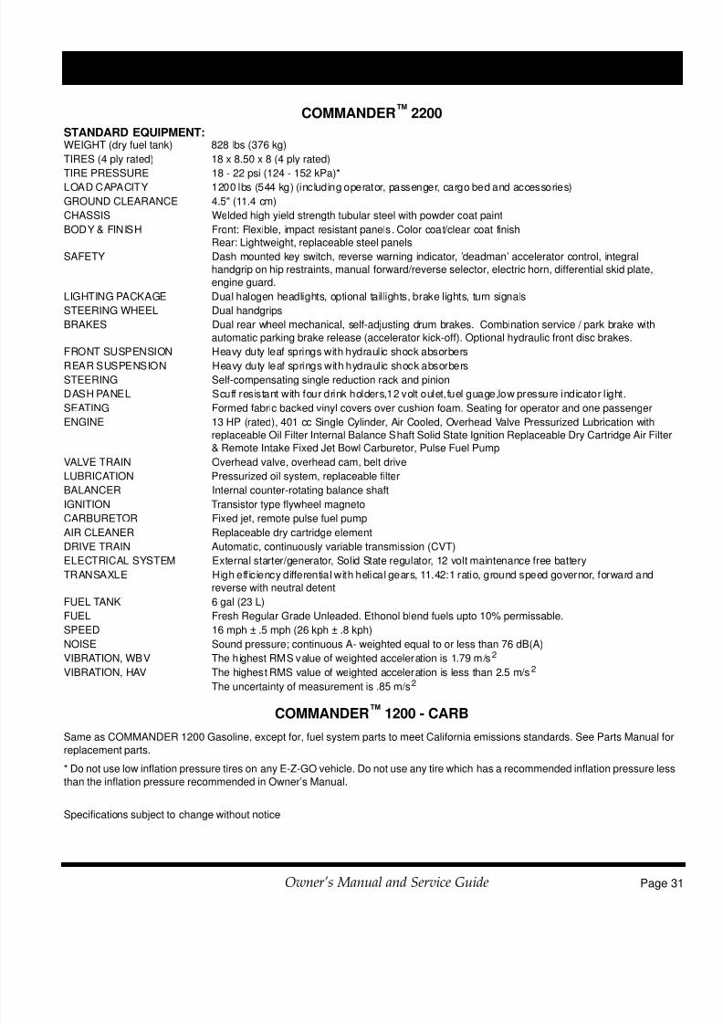
7/28/2019 606895 Commander Gas Owners Manual 2010
http://slidepdf.com/reader/full/606895-commander-gas-owners-manual-2010 47/72
Page 3Owner’s Manual and Service Guide
GENERAL SPECIFICATIONS
COMMANDER™ 2200
STANDARD EQUIPMENT:WEIGHT (dry fuel tank) 828 lbs (376 kg)
TIRES (4 ply rated) 18 x 8.50 x 8 (4 ply rated)
TIRE PRESSURE 18 - 22 psi (124 - 152 kPa)*
LOAD CAPACITY 1200 lbs (544 kg) (including operator, passenger, cargo bed and accessories)
GROUND CLEARANCE 4.5" (11.4 cm)
CHASSIS Welded high yield strength tubular steel with powder coat paint
BODY & FINISH Front: Flexible, impact resistant panels. Color coat/clear coat finish
Rear: Lightweight, replaceable steel panels
SAFETY Dash mounted key switch, reverse warning indicator, ’deadman’ accelerator control, integral
handgrip on hip restraints, manual forward/reverse selector, electric horn, differential skid plate,
engine guard.
LIGHTING PACKAGE Dual halogen headlights, optional taillights, brake lights, turn signals
STEERING WHEEL Dual handgrips
BRAKES Dual rear wheel mechanical, self-adjusting drum brakes. Combination service / park brake with
automatic parking brake release (accelerator kick-off). Optional hydraulic front disc brakes.
FRONT SUSPENSION Heavy duty leaf springs with hydraulic shock absorbers
REAR SUSPENSION Heavy duty leaf springs with hydraulic shock absorbers
STEERING Self-compensating single reduction rack and pinion
DASH PANEL Scuff resistant with four drink holders,12 volt oulet,fuel guage,low pressure indicator l ight.
SEATING Formed fabric backed vinyl covers over cushion foam. Seating for operator and one passenger
ENGINE 13 HP (rated), 401 cc Single Cylinder, Air Cooled, Overhead Valve Pressurized Lubrication with
replaceable Oil Filter Internal Balance Shaft Solid State Ignition Replaceable Dry Cartridge Air Filter
& Remote Intake Fixed Jet Bowl Carburetor, Pulse Fuel Pump
VALVE TRAIN Overhead valve, overhead cam, belt drive
LUBRICATION Pressurized oil system, replaceable filter
BALANCER Internal counter-rotating balance shaft
IGNITION Transistor type flywheel magneto
CARBURETOR Fixed jet, remote pulse fuel pump
AIR CLEANER Replaceable dry cartridge elementDRIVE TRAIN Automatic, continuously variable transmission (CVT)
ELECTRICAL SYSTEM External starter/generator, Solid State regulator, 12 volt maintenance free battery
TRANSAXLE High eff iciency differential with helical gears, 11.42:1 ratio, ground speed governor, forward and
reverse with neutral detent
FUEL TANK 6 gal (23 L)
FUEL Fresh Regular Grade Unleaded. Ethonol blend fuels upto 10% permissable.
SPEED 16 mph ± .5 mph (26 kph ± .8 kph)
NOISE Sound pressure; continuous A- weighted equal to or less than 76 dB(A)
VIBRATION, WBV The highest RMS value of weighted acceleration is 1.79 m/s2
VIBRATION, HAV The highest RMS value of weighted acceleration is less than 2.5 m/s2
The uncertainty of measurement is .85 m/s2
COMMANDER™
1200 - CARBSame as COMMANDER 1200 Gasoline, except for, fuel system parts to meet California emissions standards. See Parts Manual for
replacement parts.
* Do not use low inflation pressure tires on any E-Z-GO vehicle. Do not use any tire which has a recommended inflation pressure less
than the inflation pressure recommended in Owner’s Manual.
Specifications subject to change without notice

7/28/2019 606895 Commander Gas Owners Manual 2010
http://slidepdf.com/reader/full/606895-commander-gas-owners-manual-2010 48/72
Page 32 Owner’s Manual and Service Guide
GENERAL SPECIFICATIONS
Fig. 40 Vehicle Dimensions
COMMANDER™280
COMMANDER™2200
103 in (262 cm)
(Rear)38 in (97 cm)
(Front)37.5 in (95 cm)
35 in (89 cm)
10 in(25 cm)47 in(119 cm)
47 in(119 cm)
66 in (168 cm)
111 in (282 cm)
11.5 in(29 cm)
18 in(46 cm)
42.5 in (108 cm)
50 in(127 cm)
(Rear)38 in (97 cm)
(Front)37.5 in (95 cm)
47 in
( 119 cm)
77 in (196 cm)

7/28/2019 606895 Commander Gas Owners Manual 2010
http://slidepdf.com/reader/full/606895-commander-gas-owners-manual-2010 49/72
Page 3Owner’s Manual and Service Guide
GENERAL SPECIFICATIONS
Fig. 41 Vehicle Incline Specifications and Turning Clearance Diameter
RECOMMENDED MAX RAMP GRADE
25% or 14o MAXRECOMMENDED MAX SIDE TILT
25% or 14o MAX
TURNING CLEARANCE DIAMETER
COMMANDER™280 - 19 ft (5.8 m)
COMMANDER™2200 - 22 ft (6.7 m)

7/28/2019 606895 Commander Gas Owners Manual 2010
http://slidepdf.com/reader/full/606895-commander-gas-owners-manual-2010 50/72
Page 34 Owner’s Manual and Service Guide
GENERAL SPECIFICATIONS
NOTES:

7/28/2019 606895 Commander Gas Owners Manual 2010
http://slidepdf.com/reader/full/606895-commander-gas-owners-manual-2010 51/72
Appendix A - Owner’s Manual and Service Guide
LABELS AND PICTOGRAMS
LABELS AND PICTOGRAMS

7/28/2019 606895 Commander Gas Owners Manual 2010
http://slidepdf.com/reader/full/606895-commander-gas-owners-manual-2010 52/72
Appendix A - 2 Owner’s Manual and Service Guide
LABELS AND PICTOGRAMS
74443G01
!
1. To Prevent Roll-Back
On a Hill From a
Stopped Position
3. FullyReleasePark Brak e
2. Apply ServiceBrak e WithLeft Foot
4. Depress Accelerator While
Releasing Service Brak e As
Vehicle Starts74443G01
OFFON
71131-G01
71131G01
71489G01
35493G01 71771G0128203G01
35493-G01
2 8 2 0 3 - G 0 1
On Battery Under Seat
WARNING
Windshieldsdo not
provide protectionfrom golf ballsorother flying objects.
EGWHL14
WARNING
Keep entire body
inside car.
27653G01
DONOTTAMPERWITHORCHANGETHISADJUSTMENTOFTHE
GOVERNOR.FAILURETO COMPLYCOULDRESULTIN SERIOUS
PERSONALINJURYAND WILLVOID THEVEHICLEWARRANTY.WARNING
24880G01
H O2
1 2 3
PP
PP
PP
74093-G01
74093G01
71419G01 (24)71417G01 (25)71415G01 (26)
PP
MAX
250lbs.
114 kg
MAX
4in.
10cmMAX
14o /25%
!35980G01
35980G0135980G0235980G0335980G04
74821G0174821G02
74821G03
!
!14 25%
!
14 25%
See FollowingPages For
ExplanationOf These
Pictograms
601781
614121
cm
MIN 150
R F
ON
OFF
I
O
ON
OFF
I
OF
R
F
ON
OFF
I
O
ON
OFF
I
O
R
FON
OFF
I
O
ON
OFF
I
OR
F
< 14° 25% < 14° 25%
614121

7/28/2019 606895 Commander Gas Owners Manual 2010
http://slidepdf.com/reader/full/606895-commander-gas-owners-manual-2010 53/72
Appendix A - Owner’s Manual and Service Guide
LABELS AND PICTOGRAMS
WARNING
READ MANUAL
!
WARNING
USE CAUTION IN
INCLEMENT WEATHER
WARNING
DO NOT OPERATE
UNDER THE INFLUENCE
OF DRUGS OR ALCOHOL
MAX
14û/ 25%
MAXIMUM
CROSS HILL/RAMP
ANGLE AS SPECIFIED
!
< 14û 25%
WARNING
MAXIMUM CROSSHILL/RAMP ANGLE
AS SPECIFIED
LOAD WITH
HIGH CENTER
OF GRAVITY
COULD RESULT
IN TIP OVER
LOAD
CENTER
OF GRAVITY,
MAXIMUM
HEIGHT
x inxx cm
MAX LOADXXX LBSXXX KG
WARNINGMAXIMUM LOAD
& CENTER OF
GRAVITY.
KEEP LOAD
AS FAR
FORWARD AS
POSSIBLE.
DO NOT RIDE
IN LOAD BED
KEEP HANDS &
FINGERS AWAY
FROM DUMP BED.
DO NOT STANDBEHIND DUMP
BED
1.
13.
14.
2.
3.
4.
5.
6.
7.
8.
!
< 14û 25%
WARNING
READ MANUALFOR MAXIMUM
LOAD BED
CAPACITY.
MAXIMUM RAMP/HILL
9.
DANGER OF EXPLOSION
DO NOT FILL GAS CAN
IN LOAD BED
12.
PP
SECURE LOAD
AS FAR FORWARD
AS POSSIBLE.
MAXIMUM LOAD BED
CAPACITY
10.MAX
XXX lbs.
XXX kg
MAX
XX in.
XX cm
DO NOT RIDE IN
LOAD BED11.
NOTE: All Pictograms may not apply to your product.

7/28/2019 606895 Commander Gas Owners Manual 2010
http://slidepdf.com/reader/full/606895-commander-gas-owners-manual-2010 54/72
Appendix A - 4 Owner’s Manual and Service Guide
LABELS AND PICTOGRAMS
PP
GROUND
FUEL PUMP
PP
DO NOT
SPILL FUEL
ON A HOT
ENGINE
NO
TAMPERING.
KEEP HANDSOUT
NEGATIVE
GROUND
BATTERY
DO NOT CONNECT
POSITIVE BATTERY
TERMINAL TO GROUND
SHORTING BATTERY
TERMINALS MAY
CAUSE EXPLOSION
DO NOT
EXPOSE
TO FLAME
WARNING
CORROSIVE
WARNINGLETHAL
VOLTAGE
WARNING
EXPLOSIVE
LOW OIL PRESSURE
17.
18.
19.
20.
21.
22.
23.
24.
25.
26.
27.
DO NOT
DISPOSE OF
BATTERIES
IN LANDFILL
DO NOT
DRIVE ON
HIGHWAY
WINDSHIELDS
DO NOT
PROVIDE
PROTECTION
FROM
FLYING OBJECTS
BATTERIES ARE
HEAVY.
USE CARE LIFTING
USE INSULATED
TOOLS
28.
29.
30.
31.
32.
WEAR EYE
PROTECTION
NO SMOKING
HOT SURFACE
33.
34.
35.
OPERATE
FROM
DRIVERS SIDE
ONLY
36.
PP
UNLEADED
GASOLINE16.
1 3
H O2PP
CLEAN UP
GASOLINE
SPILLS WITH
WATER BEFORE
STARTING ENGINE
15.
2
NOTE: All Pictograms may not apply to your product.

7/28/2019 606895 Commander Gas Owners Manual 2010
http://slidepdf.com/reader/full/606895-commander-gas-owners-manual-2010 55/72
Appendix A - Owner’s Manual and Service Guide
LABELS AND PICTOGRAMS
KEEP ARMS
AND LEGS
WITHIN VEHICLE
F
TO OPERATE VEHICLE IN FORWARD:
Q TURN KEY TO ON
QMOVE DIRECTION SELECTOR TO
FORWARD
Q DEPRESS ACCELERATOR PEDAL
AND ACCELERATE SMOOTHLY
KEEP CLEAR
HAND OR
FINGERS CANBE TRAPPED
37.
38.
42.
P
F
R
TO OPERATE VEHICLE IN REVERSE:
Q TURN KEY TO ON
QMOVE DIRECTION SELECTOR TOREVERSE
Q AN AUDIBLE DEVICE WILL SOUND
QDEPRESS ACCELERATOR PEDAL
AND ACCELERATE SMOOTHLY
TO LEAVE A GASOLINE POWERED
VEHICLE IN PARK:
Q APPLY PARKING BRAKE
Q TURN KEY TO OFF
QMOVE DIRECTION SELECTOR TO
FORWARD
P
N
TO LEAVE AN ELECTRIC POWERED
VEHICLE IN PARK:
Q APPLY PARKING BRAKE
Q TURN KEY TO OFF
QMOVE DIRECTION SELECTOR TO
NEUTRAL
39.
40.
41.
ON
OFF
ON
POSITION
OFF
POSITION
HEADLIGHTS
UNLOCKED
43.
44.
45.
46.
LOCKED
47.
ENGINE
CRANKING
POSITION
DIFFERENTIAL
LOCKED48.
49.
WARNING
KEEP ENTIRE BODY
INSIDE CAR
MAXIMUM
TAILGATE
LOAD50.
51.
LEAVE VEHICLE
WHEN LIGHTNING
IS IN THE AREA
52.
MINUMUM HEIGHT
TO OPERATE VEHICLE53.
START
cm
150
NOTE: All Pictograms may not apply to your product.

7/28/2019 606895 Commander Gas Owners Manual 2010
http://slidepdf.com/reader/full/606895-commander-gas-owners-manual-2010 56/72
Appendix A - 6 Owner’s Manual and Service Guide
LABELS AND PICTOGRAMS
Notes:

7/28/2019 606895 Commander Gas Owners Manual 2010
http://slidepdf.com/reader/full/606895-commander-gas-owners-manual-2010 57/72
Appendix B -
VEHICLE WARRANTIES
Owner’s Manual and Service Guide
VEHICLE WARRANTIES

7/28/2019 606895 Commander Gas Owners Manual 2010
http://slidepdf.com/reader/full/606895-commander-gas-owners-manual-2010 58/72
Appendix B - 2 Owner’s Manual and Service Guide
VEHICLE WARRANTIES
DOMESTIC WARRANTY(U.S. AND CANADA)
To obtain a copy of the limited warranty applicable to the vehicle, call or write a local Distributor, authorized Branch
or the Warranty Department with vehicle serial number and manufacturer date code.
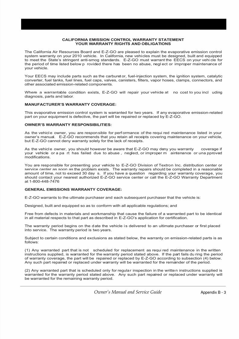
7/28/2019 606895 Commander Gas Owners Manual 2010
http://slidepdf.com/reader/full/606895-commander-gas-owners-manual-2010 59/72
Appendix B -
VEHICLE WARRANTIES - CALIFORNIA
Owner’s Manual and Service Guide
CALIFORNIA EMISSION CONTROL WARRANTY STATEMENT
YOUR WARRANTY RIGHTS AND OBLIGATIONS
The California Air Resources Board and E-Z-GO are pleased to explain the evaporative emission controlsystem warranty on your 2010 vehicle. In California, new vehicles must be designed, built and equipped
to meet the State’s stringent anti-smog standards. E-Z-GO must warrant the EECS on your vehi cle for the period of time listed below p rovided there has been no abuse, negl ect or improper maintenance of your vehicle.
Your EECS may include parts such as the carburet or, fuel-injection system, the ignition system, catalyticconverter, fuel tanks, fuel lines, fuel caps, valves, canisters, filters, vapor hoses, clamps, connectors, andother associated emission-related components.
Where a warrantable condition exists, E-Z-GO will repair your vehicle at no cost to you incl udingdiagnosis, parts and labor.
MANUFACTURER’S WARRANTY COVERAGE:
This evaporative emission control system is warranted for two years. If any evaporative emission-relatedpart on your equipment is defective, the part will be repaired or replaced by E-Z-GO.
OWNER’S WARRANTY RESPONSIBILITIES:
As the vehicl e owner, you are responsible for perf ormance of the requi red maintenance listed in your owner’s manual. E-Z-GO recommends that you retain all receipts covering maintenance on your vehicle,but E-Z-GO cannot deny warranty solely for the lack of receipts.
As the vehicle owner, you should however be aware that E-Z-GO may deny you warranty coverage if your vehicle or a pa rt has failed due to abuse , neglect, or improper m aintenance or una pprovedmodifications.
You are responsible for presenting your vehicle to E-Z-GO Division of Textron Inc. distribution center or service center as soon as the problem exists. The warranty repairs should be completed in a reasonableamount of time, not to exceed 30 day s. If you have a question regarding your warranty coverage, you
should contact your nearest authorized E-Z-GO service center or call the E-Z-GO Warranty Departmentat 1-800-448-7476
GENERAL EMISSIONS WARRANTY COVERAGE:
E-Z-GO warrants to the ultimate purchaser and each subsequent purchaser that the vehicle is:
Designed, built and equipped so as to conform with all applicable regulations; and
Free from defects in materials and workmanship that cause the failure of a warranted part to be identicalin all material respects to that part as described in E-Z-GO’s application for certification.
The warranty period begins on the date the vehicle i s delivered to an ultimate purchaser or first placedinto service. The warranty period is two years.
Subject to certain conditions and exclusions as stated below, the warranty on emission-related parts is asfollows:
(1) Any warranted part that is not scheduled for replacement as requi red maintenance in the writteninstructions supplied, is warranted for the warranty period stated above. If the part fails du ring the periodof warranty coverage, the part will be repaired or replaced by E-Z-GO according to subsection (4) below. Any such part repaired or replaced under warranty will be warranted for the remainder of the period.
(2) Any warranted part that is scheduled only for regular inspection in the written instructions supplied iswarranted for the warranty period stated above. Any such part repaired or replaced under warranty willbe warranted for the remaining warranty period.

7/28/2019 606895 Commander Gas Owners Manual 2010
http://slidepdf.com/reader/full/606895-commander-gas-owners-manual-2010 60/72
Appendix B - 4 Owner’s Manual and Service Guide
VEHICLE WARRANTIES - CALIFORNIA
(3) Any warranted pa rt that is sched uled for replacement as required maintenance in the writteninstructions supplied is warranted for the peri od of time before the first scheduled replacement date for that part. If the part fails before the first scheduled replacement, the part will be repaired or replaced by ABC, Inc. according to subsection (4) below. Any such part repaired or replaced under warranty will bewarranted for the remainder of the period prior to the first scheduled replacement point for the part.
(4) Repair or replacement of any warranted part under the warranty provisions herein must be performedat a warranty station at no charge to the owner.
(5) Notwithstanding the provisions herein, warranty services or repairs will be p rovided at all of o ur distribution centers that are franchised to service the subject engines or equipment.
(6) The vehicle owner will not be charged for diagnostic labor that is directly associated with diagnosis of a defective, emission-related warranted part, provi ded that such diagnosti c work is performed at awarranty station.
(7) E-Z-GO is liable for d amages to ot her engine or equipment components proximately caused by afailure under warranty of any warranted part.
(8) Throughout the vehicle warranty period stated above, E-Z-GO will m aintain a supply of warrantedparts sufficient to meet the expected demand for such parts.
(9) Any replacement part may be used in the pe rformance of any warranty maintenance or repairs andmust be provided without charge to the owner. Such use will not reduce the warranty obligations of E-Z-GO.
(10) Add-on or modified parts that are not exempted by the Air Resources Board may not be used. Theuse of any non-exempted add-on or modified parts by the ul timate purchaser will be grounds fo r disallowing a warranty claims. E-Z-GO will not be liable to warrant failures of warranted parts caused bythe use of a non-exempted add-on or modified part.
WARRANTED PARTS:
The repair or replacement of any wa rranted part otherwise eli gible for warranty covera ge may b eexcluded from such warranty coverage if E-Z-GO demonstrates that the vehicl e has been abused,neglected, or improperly maintained, and that such abuse, neglect, or im proper maintenance was thedirect cause of the need for repair or replacement of the part. That notwithstanding, any adjustment of acomponent that has a factory installed, and properly operating, adjustment limiting device i s still eligiblefor warranty coverage. The following emission warranty parts list are covered:
(1) Fuel Tank(2) Fuel Cap(3) Fuel Line(4) Fuel Line Fittings(5) Clamps(6) Pressure Relief Valves(7) Control Valves
(8) Control Solenoids(9) Electronic Controls(10) Vacuum Control Diaphragms(11) Control Cables(12) Control Linkages(13) Purge Valves(14) Vapor Hoses(15) Liquid/Vapor Separator (16) Carbon Canister (17) Canister Mounting Brackets(18) Carburetor Purge Port Connector

7/28/2019 606895 Commander Gas Owners Manual 2010
http://slidepdf.com/reader/full/606895-commander-gas-owners-manual-2010 61/72
Appendix B -
VEHICLE WARRANTIES - FEDERAL
Owner’s Manual and Service Guide
FEDERAL EMISSIONS COMPONENT DEFECT WARRANTY
EMISSIONS COMPONENT DEFECT WARRANTY COVERAGE - This emission warranty is applicable in all
States, except the State of California
Kawasaki Heavy Industries Ltd. and E-Z-GO Division of Textron Augusta, Georgia, (herein “E-Z-GO”) warrant(s) to
the initial retail purchaser and each subsequent owner, that this Non-road engine (herein “engine”) has beendesigned, built, and equipped to conform at the time of initial sale to all applicable regulations of the U.S.
Environmental Protection Agency (EPA), and that the engine is free of defects in materials and workmanship which
would cause this engine to fail to conform with EPA regulations during its warranty period.
For the components listed under PARTS COVERED, the distributor, dealer, or service provider authorized by E-Z-
GO will, at no cost to you, make the necessary diagnosis, repair, or replacement necessary to ensure that the
engine complies with applicable U.S. EPA regulations.
EMISSISON COMPONENT DEFECT WARRANTY PERIOD
The warranty period for this engine begins on the date of sale to the initial purchaser and continues for a period of
2 years.
PARTS COVERED
Listed below are the parts covered by the Emission Components Defect Warranty. Some of the parts listed below
may require scheduled maintenance and are warranted up to the first scheduled replacement point for that part.
Fuel Metering System
Carburetor and internal parts (and/or pressure regulator or fuel injection system)
Air/fuel ratio feedback and control system, if applicable.
Cold start enrichment system, if applicable.
Air Induction System
Intake manifold, if applicable
Air filter.
Ignition System
Spark plugs.
Magneto or electronic ignition system.
Spark advance/retard system, if applicable.
Exhaust manifold, if applicable
Miscellaneous Items Used in Above SystemsElectronic controls, if applicable
Hoses, belts, connectors, and assemblies.
OBTAINING WARRANTY SERVICE
To obtain warranty service, take your engine to the nearest authorized E-Z-GO distributor, dealer, or service
provider. Bring your sales receipts indicating date of purchase for this engine. The distributor, dealer, or service
provider authorized by E-Z-GO will perform the necessary repairs or adjustments within a reasonable amount of
time and furnish you with a copy of the repair order. All parts and accessories replaced under this warranty become
the property of E-Z-GO.
WHAT IS NOT COVERED
Conditions resulting from tampering, misuse, improper adjustment (unless they were made by the distributor,
dealer, or service provider authorized by E-Z-GO during a warranty repair), alteration, accident, failure to use
the recommended fuel and oil, or not performing required maintenance services.
The replacement parts used for required maintenance services.
Consequential damages such as loss of time, inconvenience, loss of use of the engine or equipment, etc.
Diagnosis and inspection charges that do not result in warranty-eligible service being performed.
Any non-authorized replacement part, or malfunction of authorized parts due to use of non-authorized parts.
OWNER’S WARRANTY RESPONSIBILITIES

7/28/2019 606895 Commander Gas Owners Manual 2010
http://slidepdf.com/reader/full/606895-commander-gas-owners-manual-2010 62/72
Appendix B - 6 Owner’s Manual and Service Guide
VEHICLE WARRANTIES
As the engine owner, you are responsible for the performance of the required maintenance listed in your owner’s
manual. E-Z-GO recommends that you retain all receipts covering maintenance on your engine, but E-Z-GO
cannot deny warranty solely for the lack of receipts or for your failure to ensure the performance of all scheduled
maintenance.
As the engine owner, you should however be aware that E-Z-GO may deny warranty coverage if your engine or a
part has failed due to abuse, neglect, improper maintenance or unapproved modifications.
You are responsible for presenting your engine to the nearest distributor, dealer, or service provider authorized by
E-Z-GO when a problem exists.
If you have any questions regarding your warranty rights and responsibilities, you should contact the E-Z-GO
Warranty Department at 1-800-241-5855 for the information.
THINGS YOU SHOULD KNOW ABOUT THE EMISSION CONTROL SYSTEM WARRANTY
MAINTENANCE AND REPAIRS
You are responsible for the proper maintenance of the engine. You should keep all receipts and maintenance
records covering the performance of regular maintenance in the event questions arise. These receipts and
maintenance records should be transferred to each subsequent owner of the engine. E-Z-GO reserves the right to
deny warranty coverage if the engine has not been properly maintained. Warranty claims will not be denied,
however, solely because of the lack of required maintenance or failure to keep maintenance records.
MAINTENANCE, REPLACEMENT OR REPAIR OF EMISSION CONTROL DEVICES AND SYSTEMS
MAY BE PERFORMED BY ANY REPAIR ESTABLISHMENT OR INDIVIDUAL; HOWEVER, WARRANTY
REPAIRS MUST BE PERFORMED BY A DISTRIBUTOR, DEALER OR, SERVICE PROVIDER
AUTHORIZED BY E-Z-GO. THE USE OF PARTS THAT ARE NOT EQUIVALENT IN PERFORMANCE
AND DURABILITY TO AUTHORIZED PARTS MAY IMPAIR THE EFFECTIVENESS OF THE EMISSION
CONTROL SYSTEM AND MAY HAVE A BEARING ON THE OUTCOME OF A WARRANTY CLAIM.
If other than the parts authorized by E-Z-GO are used for maintenance replacements or for the repair of
components affecting emission control, you should assure yourself that such parts are warranted by their
manufacturer to be equivalent to the parts authorized by E-Z-GO in their performance and durability.
HOW TO MAKE A CLAIM
All repair qualifying under this limited warranty must be performed by a distributor, dealer, or service provider
authorized by E-Z-GO. In the event that any emission-related part is found to be defective during the warrantyperiod, you shall notify E-Z-GO Warranty Department at 1-800-241-5855 and you will be advised of the appropriate
warranty service providers where the warranty repair can be performed.

7/28/2019 606895 Commander Gas Owners Manual 2010
http://slidepdf.com/reader/full/606895-commander-gas-owners-manual-2010 63/72
Appendix C -
DECLARATION OF CONFORMITY
Owner’s Manual and Service Guide
DECLARATION OF CONFORMITY
(EUROPE ONLY)

7/28/2019 606895 Commander Gas Owners Manual 2010
http://slidepdf.com/reader/full/606895-commander-gas-owners-manual-2010 64/72
Appendix C - 2 Owner’s Manual and Service Guide
DECLARATION OF CONFORMITY

7/28/2019 606895 Commander Gas Owners Manual 2010
http://slidepdf.com/reader/full/606895-commander-gas-owners-manual-2010 65/72
Appendix C -
DECLARATION OF CONFORMITY
Owner’s Manual and Service Guide

7/28/2019 606895 Commander Gas Owners Manual 2010
http://slidepdf.com/reader/full/606895-commander-gas-owners-manual-2010 66/72
Appendix C - 4 Owner’s Manual and Service Guide
DECLARATION OF CONFORMITY
NOTES:

7/28/2019 606895 Commander Gas Owners Manual 2010
http://slidepdf.com/reader/full/606895-commander-gas-owners-manual-2010 67/72
Read and understand the following warnings before attempting to operate the vehicle:
To prevent personal injury or death, observe the following:
When vehicle is to be left unattended, engage parking brake, move direction selector to ‘F’ (forward) position, turn key to ‘OFF’ position and remove key.Drive vehicle only as fast as terrain and safety considerations allow. Consider the terrain and traffic conditions. Consider environmental factors which effect the terrain and the ability to control the vehicle.Avoid driving fast down hill. Sudden stops or change of direction may result in a loss of control.Use service brake to control speed when traveling down an incline.Use extra care and reduced speed when driving on poor surfaces, such as loose dirt, wet grass,
gravel, etc.All travel should be directly up or down hills.Use extra care when driving the vehicle across an incline.Stay in designated areas and avoid steep slopes.Use the parking brake whenever the vehicle is parked.Keep feet, legs, hands and arms inside vehicle at all times.Avoid extremely rough terrain.Check area behind the vehicle before operating in reverse.Make sure the direction selector is in correct position before attempting to start the vehicle.
Slow down before and during turns. All turns should be executed at reduced speed.Always bring vehicle to a complete stop before shifting the direction selector.See GENERAL SPECIFICATIONS for vehicle load and seating capacity.
Read and understand the following text and warnings before
attempting to service vehicle:
In any product, components will eventually fail to perform
properly as the result of normal use, age, wear or abuse.It is virtually impossible to anticipate all possible compo-nent failures or the manner in which each componentmay fail.
Be aware that a vehicle requiring repair indicates that thevehicle is no longer functioning as designed and there-fore should be considered potentially hazardous. Useextreme care when working on any vehicle. When diag-nosing, removing or replacing any components that arenot operating correctly, take time to consider the safety ofyourself and others around you should the componentmove unexpectedly.
Some components are heavy, spring loaded, highly cor-rosive, explosive or may produce high amperage orreach high temperatures. Gasoline, carbon monoxidebattery acid and hydrogen gas could result in seriousbodily injury to the technician/mechanic and bystanders inot treated with the utmost caution. Be careful not toplace hands, face, feet or body in a location that couldexpose them to injury should an unforeseen situationoccur.
Always use the appropriate tools listed in the tool list and
wear approved safety equipment.
Before working on the vehicle, remove all jewelry(rings, watches, necklaces, etc.)
Be sure that no loose clothing or hair can contacmoving parts.
Use care not to touch hot objects.
Raise rear of vehicle and support on jack standsbefore attempting to run or adjust powertrain.
Wear eye protection when working on or aroundvehicle. In particular, use care when workingaround batteries, using solvents or compressedair.
Hydrogen gas is formed when charging batteriesDo not charge batteries without adequateventilation.
Do not permit open flame or anyone to smoke inan area that is being used for charging batteriesA concentration of 4% hydrogen gas or more isexplosive.
Engine exhaust gas (carbon monoxide) isdeadly. Carbon monoxide is an odorless,colorless gas that is formed as a natural part oincomplete combustion of hydrocarbon fuelsCarbon monoxide is a dangerous gas that cancause unconsciousness and is potentially lethal.
The following are symptoms of carbon monoxideinhalation:
• Dizziness
• Vomiting
• Intense headache
• Muscular twitching
• Weakness and sleepiness
• Throbbing in temples
If any of these symptoms are experienced, gefresh air immediately. Never work around oroperate a vehicle in an environment that does noventilate exhaust gases from the area.

7/28/2019 606895 Commander Gas Owners Manual 2010
http://slidepdf.com/reader/full/606895-commander-gas-owners-manual-2010 68/72
CUSHMAN Division Of Textron, Inc.,
1451 Marvin Griffin Road, Augusta, Georgia USA 30906-3852
TO CONTACT US
North America:
Technical Assistance & Warranty Phone: 1-800-774-3946, FAX: 1-800-448-8124
Service Parts Phone: 1-888-GET-EZGO (1-888-438-3946), FAX: 1-800-752-6175
International:
Phone: 001-706-798-4311, FAX: 001-706-771-4609
Copyrighted Material
This manual may not be reproduced in whole or
in part without the express permission of
E-Z-GO Division of Textron, Inc.
Technical Communications Department
A Textron Company

7/28/2019 606895 Commander Gas Owners Manual 2010
http://slidepdf.com/reader/full/606895-commander-gas-owners-manual-2010 69/72
Handling
Material
and
Specialist
[email protected] www.forkliftsystems.com
Fleet Management

7/28/2019 606895 Commander Gas Owners Manual 2010
http://slidepdf.com/reader/full/606895-commander-gas-owners-manual-2010 70/72
MAILING ADDRESS
Contact Info
SOCIAL MEDIA
Phone: 615-255-6321
Toll Free: 800-752-1882
Email: contact@forkliftsystems.
com
Web: www.forkliftsystems.com
Forklift Systems Incorporated
884 Elm Hill Pike
Nashville, TN 37210
CONTACT INFO

7/28/2019 606895 Commander Gas Owners Manual 2010
http://slidepdf.com/reader/full/606895-commander-gas-owners-manual-2010 71/72
Click Map to Open Google Map of Location
Tennessee Main Ofce: 884 Elm Hill Pike, Nashville, TN 37210
(615) 255-6321
Click Map to Open Google Map of Location
Alabama Main Ofce: 132 West Park Drive, Birmingham, AL 35211
(205) 945-1112

7/28/2019 606895 Commander Gas Owners Manual 2010
http://slidepdf.com/reader/full/606895-commander-gas-owners-manual-2010 72/72
Electric Pallet Trucks
Industrial Utility Vehicles Personnel Shuttles Burden Carriers
Rider Sweeper & Scrubber Walkie Sweeper & ScrubbReach Truck & Order Picker
I.C. & Electric ForkliftsLarge Capacity Forklifts
Other Products