
6000_Man
100
OPERATION AND SERVICE MANUAL Model 6330 MODEL 6330 (AC/DC HIPOT WITH IR, GROUND BOND, FUNCTIONAL RUN AND LINE LEAKAGE TESTERS) SERIAL NUMBER Models 6330 © Slaughter Company, Inc., 2013 28105 N. Keith Drive Lake Forest, Illinois, 60045-4546 U.S.A. Item 99-10522-01 Ver 1.09 Printed October 30, 2013
-
Upload
santiagocf -
Category
Documents
-
view
20 -
download
5
Transcript of 6000_Man

OPERATION AND SERVICE MANUAL
Model 6330
MODEL 6330 (AC/DC HIPOT WITH IR, GROUND BOND, FUNCTIONAL RUN AND LINELEAKAGE TESTERS)
SERIAL NUMBER
Models6330
© Slaughter Company, Inc., 201328105 N. Keith Drive
Lake Forest, Illinois, 60045-4546U.S.A.
Item 99-10522-01 Ver 1.09 Printed October 30, 2013

DECLARATION OF CONFORMITY
Manufacturer: Slaughter Company, Inc.
Address: 28105 N. Keith Dr.Lake Forest, IL 60045 USA
Product Name: AC/DC Hipot with IR, Ground Bond, FunctionalRun and Line Leakage Testers
Model Number: 6330
Conforms to the following Standards:
Safety: UL 61010-1:2012, UL 61010-2-030:2012CAN/CSA-C22.2 NO. 61010-1-12CAN/CSA-C22.2 NO. 61010-2-030-12EN 61010-1:2010, EN 61010-2-030:2010EN 61010-031:2002+A1IEC 61010-1:2010, IEC 61010-2-030:2010IEC 61010-31:2002+A1
EMC: EN61326-1:2006(EN55011:1998/A2:2002 Class A,EN 61000-3-2 :2006,EN61000-3-3:1995/A1:2001/A2:2005,EN61000-4-2:1995/A2:2000, EN61000-4-3:2002,EN61000-4-4:2004, EN61000-4-5:1995/A1:2000,EN61000-4-6:2003, EN61000-4-8:1993/A1:2000,EN61000-4-11:2004)
Supplementary Information
The product herewith complies with the requirements of the LowVoltage Directive 2006/95/EC and the EMC Directive 2004/108/EC.
Last two digits of the year the CE mark was first affixed: 08
The technical file and other documentation are on file withAssociated Research, Inc.
______________________________
Joseph GuerrieroVice President / General ManagerSlaughter Company, Inc.Lake Forest, Illinois USAOctober 30, 2013

Warranty Policy
Slaughter Company, certifies that the instrument listed in this manual meets or exceedspublished manufacturing specifications. This instrument was calibrated using standardsthat are traceable to the National Institute of Standards and Technology (NIST).
Your new instrument is warranted to be free from defects in workmanship and materialfor a period of (1) year from date of shipment. You must return the “Owners RegistrationCard” provided within (15) days from receipt of your instrument.
Slaughter Company recommends that your instrument be calibrated on a twelve-monthcycle. Instruments purchased and used in North America only, may have their warrantyextended in one year increments to a maximum of (3) years provided they are returned toSlaughter Company at least annually for calibration and inspection. The annualcalibration and inspection must be performed annually every year following receipt of theinstrument. Any instrument not calibrated and inspected annually will not be eligible forextended warranty status. This extended warranty is non-transferable and is offered onlyto the original purchaser. A return material authorization (RMA) must be obtained fromSlaughter Company. Please contact our Customer Support Center at 1-800-504-0055 toobtain an RMA number. It is important that the instrument is packed in its originalcontainer for safe transport. If the original container in not available please contact ourcustomer support center for proper instructions on packaging. Damages sustained as aresult of improper packaging will not be honored. Transportation costs for the return ofthe instrument for warranty service must be prepaid by the customer. SlaughterCompany will assume the return freight costs when returning the instrument to thecustomer. The return method will be at the discretion of Slaughter Company.
Except as provided herein, Slaughter Company makes no warranties to the purchaser ofthis instrument and all other warranties, express or implied (including, without limitation,merchantability or fitness for a particular purpose) are hereby excluded, disclaimed andwaived.
Any non-authorized modifications, tampering or physical damage will void yourwarranty. Elimination of any connections in the earth grounding system or bypassing anysafety systems will void this warranty. This warranty does not cover batteries oraccessories not of Slaughter Company manufacture. Parts used must be parts that arerecommended by Slaughter Company as an acceptable specified part. Use of non-authorized parts in the repair of this instrument will void the warranty.


i
TABLE OF CONTENTS
SECTION 1 OPERATORS MANUAL ........................................................................ 1
SAFETY ...................................................................................................................... 2
INTRODUCTION ....................................................................................................... 7
SPECIFICATIONS .................................................................................................... 13
CONTROLS .............................................................................................................. 21
INSTALLATION ...................................................................................................... 25
QUICK START ......................................................................................................... 30
OPERATION ............................................................................................................. 33
BUS REMOTE INTERFACE: RS-232 ....................................................................... 66
OPTIONS .................................................................................................................. 77
SECTION 2 SERVICE MANUAL ............................................................................. 79
CALIBRATION ........................................................................................................ 80
PARTS ...................................................................................................................... 92
SCHEMATICS .......................................................................................................... 94


SECTION 1OPERATORS MANUAL

SAFETY
2
SAFETY PRECAUTIONS REQUIRED FOR HIGH VOLTAGETESTING!
GENERALThis product and its related documentation must be reviewed for familiarization withsafety markings and instructions before operation.
This product is a Safety Class I instrument (provided with a protective earth terminal).
Before applying power verify that the instrument is set to the correct line voltage (115 or230) and the correct fuse is installed.
INSTRUCTION MANUAL SYMBOL. PLEASE REFER TO THEINSTRUCTION MANUAL FOR SPECIFIC WARNING OR CAUTIONINFORMATION TO AVOID PERSONAL INJURY OR DAMAGE TO THEPRODUCT.
INDICATES HAZARDOUS VOLTAGES MAY BE PRESENT.
CHASSIS GROUND SYMBOL.
CALLS ATTENTION TO A PROCEDURE, PRACTICE, ORCONDITION, THAT COULD POSSIBLY CAUSE BODILYINJURY OR DEATH.
CALLS ATTENTION TO A PROCEDURE, PRACTICE, ORCONDITION, THAT COULD POSSIBLY CAUSE DAMAGETO EQUIPMENT OR PERMANENT LOSS OF DATA.

SAFETY
3
A Hipot produces voltages and currents which can cause harmful or fatal electricshock. To prevent accidental injury or death, these safety procedures must be strictlyobserved when handling and using the test instrument.
SERVICE AND MAINTENANCE
User ServiceTo prevent electric shock do not remove the instrument cover. There are no userserviceable parts inside. Routine maintenance or cleaning of internal parts is notnecessary. Any external cleaning should be done with a clean dry or slightly damp cloth.Avoid the use of cleaning agents or chemicals to prevent any foreign liquid from enteringthe cabinet through ventilation holes or damaging controls and switches, also somechemicals may damage plastic parts or lettering. Schematics, when provided, are forreference only. Any replacement cables and high voltage components should be acquireddirectly from Slaughter Company, Inc. Refer servicing to a Slaughter Company, Inc.authorized service center.
SLAUGHTER COMPANY, INC.28105 N. KEITH DRIVE
LAKE FOREST, IL 60045-4546 U.S.A.
(PHONE: 1 (847) 932-36621 (800) 504-0055
FAX: 1 (847) 932-3665E-MAIL : [email protected]
www.hipot.com
Service IntervalThe instrument and its power cord, test leads, and accessories must be returned at leastonce a year to a Slaughter Company authorized service center for calibration andinspection of safety related components. Slaughter Company will not be held liable forinjuries suffered if the instrument is not returned for its annual safety check andmaintained properly.
User ModificationsUnauthorized user modifications will void your warranty. Slaughter Company will notbe responsible for any injuries sustained due to unauthorized equipment modifications oruse of parts not specified by Slaughter Company. Instruments returned to SlaughterCompany with unsafe modifications will be returned to their original operating conditionat your expense.
TEST STATION
LocationSelect an area away from the main stream of activity which employees do not walkthrough in performing their normal duties. If this is not practical because of productionline flow, then the area should be roped off and marked for HIGH VOLTAGETESTING. No employees other than the test operators should be allowed inside.

SAFETY
4
If benches are placed back-to-back, be especially careful about the use of the benchopposite the test station. Signs should be posted: "DANGER - HIGH VOLTAGETEST IN PROGRESS - UNAUTHORIZED PERSONNEL KEEP AWAY."
PowerDielectric Voltage-Withstand Test Equipment must be connected to a good ground. Becertain that the power wiring to the test bench is properly polarized and that the properlow resistance bonding to ground is in place.
Power to the test station should be arranged so that it can be shut off by one prominentlymarked switch located at the entrance to the test area. In the event of an emergency,anyone can cut off the power before entering the test area to offer assistance.
The mains plug is used as the disconnecting device and shallremain readily operable. The socket-outlet shall be installed nearthe equipment and shall be easily accessible.
Do not replace the power supply cord with an improperly ratedcord. For North American: A UL listed and CSA labeled powercord must be used with the instrument in the United States and
Canada. The power cord must include a NEMA5-15 style male plug, SVT or SJT cordsets, and be rated for at least 125VAC, 10A, number 16 gauge (or 125VAC, 15A, number14 gauge) wire or larger, and the length of the cord does not exceed 2 m must be used.For European: A certified power supply cord not lighter than light PVC sheathed flexiblecord according to IEC 60227, designation H03 VV-F or H03 VVH2-F (for equipmentmass not exceeding 3 kg), or H05 VV-F or H05 VVH2-F2 (for equipment massexceeding 3 kg), and be rated for at least 3G 0.75 mm² (for rated current up to 10 A) or3G 1.0mm² (for rated current over 10 A up to 16 A) wire or larger, and the length of thecord does not exceed 2 m must be used.
Work AreaPerform the tests on a non-conducting table or workbench, if possible.
There should not be any metal in the work area between the operator and the locationwhere products being tested will be positioned.
Position the tester so the operator does not have to reach over the product under test toactivate or adjust the tester. If the product or component being tested is small, it may bepossible to construct guards or an enclosure, made of a non-conducting material such asclear acrylic, such that the item being tested is within the guards or enclosure during thetest, and fit them with switches so that the tester will not operate unless the guards are inplace or the enclosure closed.
Keep the area clean and uncluttered. All test equipment and test leads not absolutelynecessary for the test should be removed from the test bench and put away. It should beclear to both the operator and to any observers which product is being tested, and whichones are waiting to be tested or have already been tested.

SAFETY
5
Do not perform Hipot tests in a combustible atmosphere or in any area wherecombustible materials are present.
TEST OPERATOR
QualificationsThis instrument generates voltages and currents which can cause harmful or fatalelectric shock and must only be operated by a skilled worker trained in its use.
The operator should understand the electrical fundamentals of voltage, current, andresistance.
Safety ProceduresOperators should be thoroughly trained to follow these and all other applicable safetyrules and procedures before they begin a test. Defeating any safety system should betreated as a serious offense and should result in severe penalties, such as removal fromthe Hipot testing job. Allowing unauthorized personnel in the area during a test shouldalso be dealt with as a serious offense.
DressOperators should not wear jewelry which could accidentally complete a circuit.
Medical RestrictionsThis instrument should not be operated by personnel with heart ailments or devices suchas pacemakers.
TEST PROCEDURES
NEVER PERFORM A HIPOT TEST ON ENERGIZEDCIRCUITRY OR EQUIPMENT!
If the instrument has an external safety-ground connection, be sure that this is connected.Then connect the return lead first for any test regardless of whether the item under test isa sample of insulating material tested with electrodes, a component tested with the highvoltage test lead, or a cord-connected device with a two or three-prong plug.
Plug in the high voltage test lead only when it is being used. Handle its clip only by thered insulator sleeve---never touch the clip directly. Be certain that the operator hascontrol over any remote test switches connected to the Hipot. Double-check the returnand high voltage connections to be certain that they are proper and secure.
NEVER TOUCH THE ITEM UNDER TEST ORANYTHING CONNECTED TO IT WHILE HIGHVOLTAGE IS PRESENT DURING THE HIPOT TEST.
DO NOT TOUCH THE FRONT PANEL WHEN TESTINGOR AFTER A MALFUNCTION HAS OCCURRED.

SAFETY
6
When testing with DC, always discharge the capacitance of the item under test andanything the high voltage may have contacted--such as test fixtures--before handling it ordisconnecting the test leads.
HOT STICK probes can be used to discharge any capacitance in the item under test as afurther safety precaution. A hot stick is a non-conducting rod about two feet long with ametal probe at the end which is connected to a wire. To discharge the device under test,two hot sticks are required. First connect both probe wires to a good earth ground. Thentouch one probe tip to the same place the return lead was connected. While holding thefirst probe in place, touch the second probe tip to the same place where the high voltagelead was connected.
KEY SAFETY POINTS TO REMEMBER
• Keep unqualified and unauthorized personnel away from the test area.• Arrange the test station in a safe and orderly manner.• Never touch the product or connections during a test.• In case of any problem, turn off the high voltage first.• Properly discharge any item tested with DC before touching connections.

INTRODUCTION
7
GLOSSARY OF TERMS(as used in this manual)
Alternating Current, AC: Current which reverses direction on a regular basis, commonly in theU.S.A. 60 times per second, in other countries 50 times per second.
Breakdown: The failure of insulation to effectively prevent the flow of current, sometimes evident byarcing. If voltage is gradually raised, breakdown will begin suddenly at a certain voltage level. Currentflow is not directly proportional to voltage. Once breakdown current has flown, especially for a period oftime, a repeated application of voltage will often show breakdown beginning at a lower voltage thaninitially.
Conductor: A solid or liquid material which has the ability to let current pass through it, and which hasa volume resistivity of no more than 103 ohm-cm.
Current: The movement of electrons through a conductor. Current is measured in amperes,milliamperes, microamperes, nanoamperes, or picoamperes. Symbol = I
Dielectric: An insulating material which is positioned between two conductive materials in such a waythat a charge or voltage may appear across the two conductive materials.
Direct Current, DC: Current which flows in one direction only. The source of direct current is saidto be polarized and has one terminal which is always at a higher potential than the other.
Insulation: Gas, liquid or solid material which has a volume resistivity of at least 1012 ohm-cm and isused for the purpose of resisting current flow between conductors.
Leakage: AC or DC current flow through insulation and over its surfaces, and AC current flow througha capacitance. Current flow is directly proportional to voltage. The insulation and/or capacitance isthought of as a constant impedance, unless breakdown occurs.
Measuring Device (MD): A resistive and capacitive network used to simulate the impedance of thehuman body during Line Leakage testing.
Resistance: That property of a substance which impedes current and results in the dissipation of powerin the form of heat. The practical unit of resistance is the ohm. Symbol = R
Trip Point: The minimum current flow required to cause an indication of unacceptable performanceduring a dielectric voltage-withstand test.
Voltage: Electrical pressure, the force which causes current through an electrical conductor. Symbol = V

INTRODUCTION
8
INTRODUCTION
The importance of testing.... User safetyIn an era of soaring liability costs, original manufacturers of electrical and electronicproducts must make sure every item is as safe as possible. All products must be designedand built to prevent electric shock, even when users abuse the equipment or bypass built-in safety features.
To meet recognized safety standards, one common test is the "dielectric voltage-withstand test". Safety agencies which require compliance safety testing at both theinitial product design stage and for routine production line testing include: UnderwritersLaboratories, Inc. (UL), the Canadian Standards Association (CSA), the InternationalElectrotechnical Commission (IEC), the British Standards Institution (BSI), theAssociation of German Electrical Engineers (VDE), the Japanese Standards Association(JSI). These same agencies may also require that an insulation resistance test and highcurrent ground bond test be performed.
The Dielectric Withstand (Hipot) Test....The principle behind a dielectric voltage-withstand test is simple: if a product willfunction when exposed to extremely adverse conditions, it can be assumed that theproduct will function in normal operating circumstances.
The most common applications of the dielectric-withstand test are:
• Design (performance) Testing.... determining design adequacy to meet serviceconditions.
• Production Line Testing.... detecting defects in material or workmanship duringprocessing.
• Acceptance Testing.... proving minimum insulation requirements of purchased parts.
• Repair Service Testing.... determine reliability and safety of equipment repairs.
During a dielectric voltage-withstand test, an electrical devise is exposed to a voltagesignificantly higher than it normally encounters. The high voltage is continued for agiven period of time.
If stray current flow remains within specified limits during the time the component istested, the device is assumed to be safe under normal conditions.
The equipment used for this test, a dielectric-withstand tester, is often called a "Hipot"(for high potential tester). The "rule of thumb" for testing is to subject the product totwice its normal operating voltage, plus 1,000 volts. However, specific products may betested at much higher voltages than 2X operating voltages + 1,000 volts.

INTRODUCTION
9
For example, a product designed to operate in the range between 100 to 240 volts can betested between 1,000 to 4,000 volts, or higher. Most "double insulated" products aretested at voltages much higher than the "rule of thumb."
Testing during development and prototype stages is more stringent than production linetesting because the basic design of the product is evaluated. Design tests are usuallyperformed on only a few samples of the product. Production line tests are performed onevery item as it comes off the production line.
The Hipot tester must also maintain an output voltage between 100% and 120% ofspecification. The output voltage of the Hipot must have a sinusoidal waveform with afrequency between 40 to 70 Hz and has a peak waveform value that is not less than 1.3and not more than 1.5 times the root-mean-square value.
Advantages and Disadvantages of AC Testing and DC Testing....Please check with the Compliance Agency you are working with to see which of the twotypes of voltages you are authorized to use. In some cases, a Compliance Agency willallow either AC or DC testing. However, in other cases the Compliance Agency onlyallows for an AC test. If you are unsure which specification you must comply with,please contact our SALES DEPARTMENT at 1-800-504-0055.
AC testing characteristics
Most items that are Hipot tested have some amount of distributed capacitance. An ACvoltage cannot charge this capacitance so it continually reads the reactive current thatflows when an AC voltage is applied to a capacitive load.
AC testing advantages
1. AC testing is generally more accepted by safety agencies than DC testing. Themain reason for this is that most items being Hipot tested will operate at ACvoltages. AC Hipot testing offers the advantage of stressing the insulationalternately in both polarities, which more closely simulates stresses the product willnormally see.
2. Since AC testing cannot charge a capacitive load the current reading remainsconsistent from the initial application of the voltage, to the end of the test. There isno need to gradually bring up the voltage since no stabilization is required tomonitor the current reading. Unless the product is sensitive to a sudden applicationof voltage, the operator can immediately apply full voltage and read current withoutany wait time.
3. Since AC voltage cannot charge a load there is no need to discharge the item undertest after the test.

INTRODUCTION
10
AC testing disadvantages
1. Again, since AC cannot charge the item under test, reactive current is constantlyflowing. In many cases, the reactive component of the current can be much greaterthan the real component due to actual leakage. This can make it very difficult todetect products that have excessively high leakage current.
2. The Hipot has supply reactive and leakage current continuously. This may require acurrent output that is actually much higher than is really required to monitor leakagecurrent, and in most cases is usually much higher than would be needed with a DCtester. This can present increased safety risks as operators are exposed to highercurrents.
DC testing characteristics
During DC Hipot testing the item under test is charged. The capacitance that causesreactive current in AC testing will now result in charging current, which exponentiallydrops to zero during DC testing.
DC testing advantages
1. Once the item under test is fully charged the only current flowing is the true leakagecurrent. The DC Hipot tester clearly displays only the true leakage of the productunder test.
2. Since the charging current only needs to be applied momentarily, the output powerrequirements of the DC Hipot tester can typically be much less than what would berequired in an AC tester.
DC testing disadvantages
1. Unless the item being tested has virtually no capacitance, it is necessary to raise thevoltage gradually from zero to the full test voltage. The more capacitive the itemthe more slowly the voltage must be raised. This is important since most DC Hipotshave failure shut-off circuitry, which will indicate a failure almost immediately ifthe total current reaches the leakage threshold during the initial charging of theproduct under test.
2. Since a DC Hipot does charge the item under test, it becomes necessary to dischargethe item after the test.
3. A DC Hipot test only charges the insulation in one polarity. This becomes aconcern when testing products that will be used with AC voltages. As such, somesafety agencies do not accept DC testing as an alternative to AC testing.
4. When performing AC Hipot tests, the product under test is actually tested with peakvoltages that the Hipot meter does not display. This is not the case with DC testingsince a sine wave is not generated when testing with a DC voltage. In order to

INTRODUCTION
11
compensate for this fact, most safety agencies require that the equivalent DC test beperformed at a higher voltage than the AC test. The multiplying factor is somewhatinconsistent between agencies, which can cause confusion.
The Insulation Resistance Test....Some dielectric analyzers today come with a built-in insulation resistance tester.Typically, the IR function provides test voltages from 500 to 1,000 volts DC andmeasures resistance from kilohms to gigohms. BABT, TÜV, and VDE are agencies thatmay, under certain conditions, require an IR test on the product before a Hipot test isperformed. IR testing typically is not done on the production line, but as a performancedesign test.
The IR test is very similar to the Hipot test. Instead of the go/no go indication that youget with a Hipot test, the IR test indicates an insulation value, usually in Megohms.Typically the higher the IR value, the better the condition of the insulation. Themeasured value represents the equivalent resistance of all the insulation between the twotest points, and any component resistance which might also be connected between thetwo points. The connections to perform the IR test are the same as the Hipot test.
Although the IR test can predict insulation condition, it does not replace the need toperform a Dielectric Withstand test.
TYPES OF FAILURES DETECTABLE ONLY WITH A HIPOT TEST
• Weak Insulating Materials• Pinholes in Insulation• Inadequate Spacing of Components• Pinched Insulation
Why Perform a Ground Bond Test… .Ground Bond testing is done to ensure that a low resistance path exists between the safetyground pin of a three-wire line cord and exposed metal of the device under test. Ideally,if a live wire inside the item under test became loose and contacted the chassis, the faultcurrent would flow through the low resistance safety ground, and protect the user.
The need for high current bonding (i.e. 30A or 60A) as apposed to low current go-no gotype testers, is the result of the line voltage breakers’ high current characteristics. Safetygrounding circuits must withstand the line voltage breaker’s current rating in order tomaintain safe voltage potentials on the chassis of the faulty device. Verifying theintegrity of the grounding circuit at high currents ensures that the line breaker will openbefore the grounding circuit wires fail.
The Line Leakage Test… .The Line Leakage test measures the amount of leakage current that is produced while aproduct is running. The test is unique in that it is performed while the DUT is running,thus an external power supply is required to perform the test properly. Usually the userneeds to supply the voltage source to power the DUT.

INTRODUCTION
12
Line Leakage tests use impedance models called measuring devices (MD’s) to measurehow much leakage current is being produced by a DUT under several conditions: normal,reversed input polarity, open neutral, and open ground. Performing a Line Leakage testgives manufacturers the opportunity to know how much leakage current a user will besubjected to under a variety of different circumstances.
Line Leakage testing is commonly performed as a design/type test during new productdevelopment. Configuration “G-L” represents an earth leakage test which measures theleakage current from the DUT’s protective earth ground back to the system neutral.
Why Perform a Functional Run Test… .Functional Run testing, although not considered to be an electrical safety test, isworthwhile to perform for a variety of reasons. The Functional Run test is primarily usedto determine if a DUT runs properly after it has been subjected to a battery of electricalsafety tests. Usually the test monitors various parameters including: input voltage, inputcurrent, input power, and input power factor. Test operators can use the informationgained from the Functional Run test to determine if a DUT is operating properly beforethe unit is shipped to a customer. This is beneficial since there is no electrical safety testthat can conclude if a product will power up and operate properly.
IF YOU SHOULD HAVE ANY QUESTIONS RELATING TO THE OPERATIONOF YOUR INSTRUMENT CALL 1 (800) 504-0055 IN THE U.S.A.

SPECIFICATIONS
13
MODEL 6330 FUNCTIONAL SPECIFICATIONS
Unless otherwise stated, accuracy's are relative to a laboratory standard measurement.INPUTVoltage 115 / 230V selectable, ± 10 % variationFrequency 50 / 60 Hz ± 5%Fuse 6.3 A slow blow 250V ACDIELECTRIC WITHSTAND TEST MODEOutput Rating 3.5 kV @ 30 mA AC
4.0 kV @ 5 mA DCVoltage Setting Range: 0.00 – 3.50 kV AC
0.00 – 4.00 kV DCResolution: 0.01 kVAccuracy: ± (2 % of setting + 5 V)
Voltage Display Range: 0.00 – 3.50 kV AC0.00 – 4.00 kV DC
Resolution: 0.01 kVAccuracy: ± (2 % of reading + 10 V)
Current Display Range: 0.00 – 30.00 mA AC0.00 – 5.00 mA DC
Resolution: 0.01 mAAccuracy: ± (2 % of reading + 0.02 mA)
HI and LO-Limit Range: 0.00 – 30.00 mA ACResolution: 0.01 mAAccuracy: ± (2 % of setting + 0.02 mA)Range: 0.00 – 5.00 mA DCResolution: 0.01 mAAccuracy: ± (2 % of setting + 0.02 mA)
Failure Detector Audible and VisualDC Output Ripple ≤ 5% Ripple RMS at 6 KV DC @ 5 mA, resistive loadDischarge Time ≤ 200 msMaximum CapacitiveLoad in DC Mode
1 uF < 1 kV0.75 uF < 2 kV0.5 uF < 3 kV
0.08 uF < 4.0kV
AC Output Waveform Sine Wave, Crest Factor = 1.3 – 1.5AC Output Frequency Range: 60 or 50 Hz, User Selectable
Accuracy: ± 0.1 %Output Regulation ± (1 % of setting + 5 V) from no load to full loadDwell Timer Range: 0, 0.2 – 999.9 sec (0 = Continuous)
Resolution: 0.1 secAccuracy: ± (0.1 % + 0.05 sec)
Ramp Timer Range: 0.1 – 999.9 secResolution: 0.1 secAccuracy: ± (0.1 % + 0.05 sec)
INSULATION RESISTANCE TEST MODE
SPECIFICATIONS
14
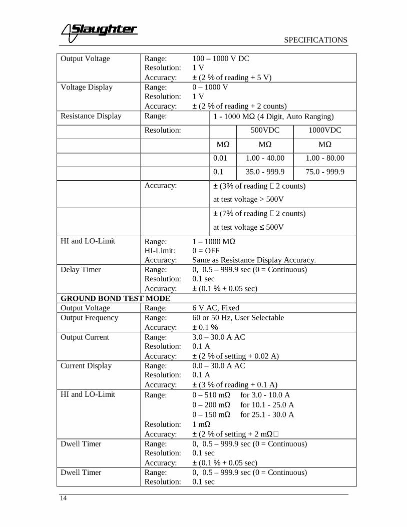
Output Voltage Range: 100 – 1000 V DCResolution: 1 VAccuracy: ± (2 % of reading + 5 V)
Voltage Display Range: 0 – 1000 VResolution: 1 VAccuracy: ± (2 % of reading + 2 counts)
Resistance Display Range: 1 - 1000 MΩ (4 Digit, Auto Ranging)
Resolution: 500VDC 1000VDC
MΩ MΩ MΩ
0.01 1.00 - 40.00 1.00 - 80.00
0.1 35.0 - 999.9 75.0 - 999.9
Accuracy: ± (3% of reading + 2 counts)
at test voltage > 500V
± (7% of reading + 2 counts)
at test voltage ≤ 500V
HI and LO-Limit Range: 1 – 1000 MΩHI-Limit: 0 = OFFAccuracy: Same as Resistance Display Accuracy.
Delay Timer Range: 0, 0.5 – 999.9 sec (0 = Continuous)Resolution: 0.1 secAccuracy: ± (0.1 % + 0.05 sec)
GROUND BOND TEST MODEOutput Voltage Range: 6 V AC, FixedOutput Frequency Range: 60 or 50 Hz, User Selectable
Accuracy: ± 0.1 %Output Current Range: 3.0 – 30.0 A AC
Resolution: 0.1 AAccuracy: ± (2 % of setting + 0.02 A)
Current Display Range: 0.0 – 30.0 A ACResolution: 0.1 AAccuracy: ± (3 % of reading + 0.1 A)
HI and LO-Limit Range: 0 – 510 mΩ for 3.0 - 10.0 A0 – 200 mΩ for 10.1 - 25.0 A0 – 150 mΩ for 25.1 - 30.0 A
Resolution: 1 mΩAccuracy: ± (2 % of setting + 2 mΩ)
Dwell Timer Range: 0, 0.5 – 999.9 sec (0 = Continuous)Resolution: 0.1 secAccuracy: ± (0.1 % + 0.05 sec)
Dwell Timer Range: 0, 0.5 – 999.9 sec (0 = Continuous)Resolution: 0.1 sec

SPECIFICATIONS
15
Accuracy: ± (0.1 % + 0.05 sec)Milliohm Offset Range: 0 – 100 mΩ
Resolution: 1 mΩAccuracy: ± (2 % of setting + 2 mΩ)
FUNCTIONAL RUN TEST MODEDUT POWERAC Voltage 0 - 277.0 V, Single phase unbalanced, 0 - 30.0 A maximumCurrent 30 A maximum continuousPower Rating 8400 W maximumDUT Protection Short Circuit current 50 A < 3 s, Inrush Current 180 A Response
time 10 us.SETTINGS
Range Resolution AccuracyHI and LO Limit ACVoltage, V 0.0 - 277.0 0.1 ± (1.5% of setting + 0.2
V), 60.0-277 VHI and LO Limit ACCurrent, A 0.0 - 30.0 0.1 ± (2% of setting + 2
counts)HI and LO Limit AC Power,W 0 - 8400 1 ± (5% of setting + 6
counts)
HI and LO Limit PowerFactor 0.000 - 1.000 0.001
W/VA, calculated anddisplayed to threesignificant digits
HI and LO Limit LeakageCurrent
0.00 - 10.00, Hi-Limit 0=OFF 0.01 ± (2% of setting + 2
counts)Delay Time, second 0.2 - 999.9
0.1 ± (0.1% + 0.05 sec)Dwell Time, second 0, 0.1 - 999.9(0=continuous)
MEASUREMENTRange Resolution Accuracy
Voltage, Vac 0.0 - 277.0 0.1 ± (1.5% of reading + 2counts), 60.0~277 V
Current, Aac 0.0 - 30.0 0.1 ± (2% of reading + 2counts)
Power, Watts 0 - 8400 1 ± (5% of reading + 6counts)
Power, Factor 0.000 - 1.000 0.001W/VA, calculated and
displayed to threesignificant digits
Leakage Current, mA 0.00 - 10.00 0.01 ± (2% of reading + 2counts)
MD Circuit Leakage Current measuring resistance = 2K ±1%
Timer, second 0.0 - 999.9 0.1 ± (0.1% of reading +0.05 sec)
LINE LEAKAGEDUTDUT Input Power 0 - 277.0 V, Single phase unbalanced, 30 A maximum
SPECIFICATIONS
16
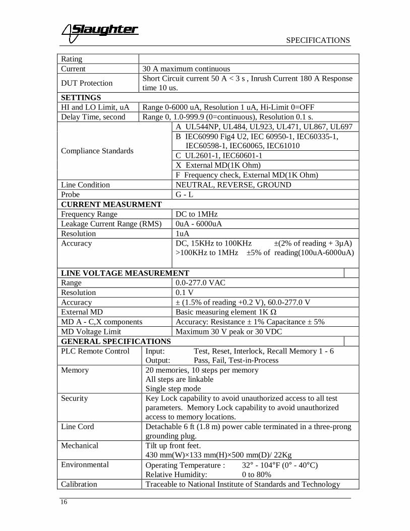
RatingCurrent 30 A maximum continuous
DUT Protection Short Circuit current 50 A < 3 s , Inrush Current 180 A Responsetime 10 us.
SETTINGSHI and LO Limit, uA Range 0-6000 uA, Resolution 1 uA, Hi-Limit 0=OFFDelay Time, second Range 0, 1.0-999.9 (0=continuous), Resolution 0.1 s.
Compliance Standards
A UL544NP, UL484, UL923, UL471, UL867, UL697B IEC60990 Fig4 U2, IEC 60950-1, IEC60335-1, IEC60598-1, IEC60065, IEC61010C UL2601-1, IEC60601-1X External MD(1K Ohm)F Frequency check, External MD(1K Ohm)
Line Condition NEUTRAL, REVERSE, GROUNDProbe G - LCURRENT MEASURMENTFrequency Range DC to 1MHzLeakage Current Range (RMS) 0uA - 6000uAResolution 1uAAccuracy DC, 15KHz to 100KHz ±(2% of reading + 3µA)
>100KHz to 1MHz ±5% of reading(100uA-6000uA)
LINE VOLTAGE MEASUREMENTRange 0.0-277.0 VACResolution 0.1 VAccuracy ± (1.5% of reading +0.2 V), 60.0-277.0 VExternal MD Basic measuring element 1K MD A - C,X components Accuracy: Resistance ± 1% Capacitance ± 5%MD Voltage Limit Maximum 30 V peak or 30 VDCGENERAL SPECIFICATIONSPLC Remote Control Input: Test, Reset, Interlock, Recall Memory 1 - 6
Output: Pass, Fail, Test-in-ProcessMemory 20 memories, 10 steps per memory
All steps are linkableSingle step mode
Security Key Lock capability to avoid unauthorized access to all testparameters. Memory Lock capability to avoid unauthorizedaccess to memory locations.
Line Cord Detachable 6 ft (1.8 m) power cable terminated in a three-pronggrounding plug.
Mechanical Tilt up front feet.430 mm(W)×133 mm(H)×500 mm(D)/ 22Kg
Environmental Operating Temperature : 32° - 104°F (0° - 40°C)Relative Humidity: 0 to 80%
Calibration Traceable to National Institute of Standards and Technology

SPECIFICATIONS
17
(NIST). Calibration controlled by software. Adjustments aremade through front panel keypad in a restricted accesscalibration mode. Calibration information stored in non-volatilememory.
SPECIFICATIONS
18
KEY FEATURES & BENEFITS OF MODEL 6330
1. Tamper proof front panel controls.This makes it possible to limit user access to the setup screens so that only authorizedpersonnel can change test parameters.
2. Multiple Test Memories.The 6330 provides twenty test memories with ten steps per memory. This is beneficialfor manufacturers testing multiple products on one production line.
3. Low-current sense.The low current sense feature monitors the minimum level of current flow, thusensuring that the DUT is properly connected and that the Hipot test is beingperformed.
4. Simple Menu Control.All parameters for the setups can be adjusted through a simple menu driven program.The easy to follow setup screens ensure that the operator correctly sets up all testparameters.
5. Electronic dwell settings.The electronic dwell control helps keep test results consistent by ensuring that the testduration is the same for each product tested.
6. Electronic ramping.Electronic ramping provides a gradual and timed method to increase output voltage tothe DUT, minimizing any damage from quickly over-applying high voltage to sensitiveDUTs.
7. Front panel LCD.A front panel LCD allows the operator to monitor the test. The display holds theresults after a test item failure so that the operator can easily review the test results.Failure indications are clearly displayed.
8. No load setup of trip current and output voltage.This provides the operator with an easy and safe way to set trip currents and outputvoltages since parameters are set without the high voltage present.
9. Storage of test program.The 6330 powers up with the same parameters that were used during the last test toavoid operator set up errors.
10. Output voltage fine adjustment.To make the 6330 usable in all types of applications, the operator can manually bringthe voltage up or down in 10 volt increments by simply pressing the up and downarrow keys. This makes it very easy to adjust the output voltage even while theinstrument is in the dwell mode so you can analyze test results at different voltages.

SPECIFICATIONS
19
11. Software calibration control.The 6330 is calibrated through the front panel keypad. All calibration information isstored in non-volatile memory. This allows the instrument to be completely calibratedwithout removing any covers and exposing the technician to hazardous voltages.
12. Current monitoring.The LCD display allows monitoring of current down to 10 microamps AC and 10microamps DC. This allows the 6330 to be used even when test requirements onlyallow a very low level of acceptable leakage current.
13. Line and load regulation.This system maintains the output voltage to within 1% from no load to full load andover the line voltage range to ensure that test results remain consistent and withinsafety agency requirements.
14. PLC remote inputs and outputs.The standard 9- pin interfaces provide outputs for Pass, Fail, and Test in Process.Inputs include Test, Reset, Interlock, and Memory Recall. This gives the user all thebasic remotes required to configure the instrument through simple PLC relay control.
15. Flashing high voltage indicator.A flashing LED located directly over the high voltage terminal clearly indicates whenhigh voltage is active to provide maximum operator safety.
16. Single Step Test Mode.In this mode, the 6330 can be configured to perform each test individually as a singlestep. This provides the manufacturers flexibility in configuring their testingprocedure.
17. Insulation Resistance and Ground Bond Test Modes.This allows the operator to perform an Insulation Resistance or Ground Bond testswith the Dielectric Withstand (Hipot) test, thus eliminating the need for a separatepieces of test equipment when IR and Ground Bond testing is required.
18. Continuous Duty Cycle Ratings.An advantage over other instruments in its class, the 6330 does not have anyrequirement to be shut down during the day even when used at full output.
19. Milliohm Offset Capability.This feature minimizes the effect of test lead or test fixture resistance.
20. Adjustable Output Current and Milliohm Trip Currents.The 6330 is versatile enough to meet a wide variety of safety agency specifications.
21. Key Lockout.When enabled, Key Lockout disables all front panel keys except TEST and RESET.
22. Memory Lock

SPECIFICATIONS
20
Memory Lock is a sub-function of Key Lockout. When enabled, the operator will onlyhave access to the TEST and RESET keys. When disabled, the operator will be able totoggle between memory locations but not alter them.
23. Fail Stop ON/OFF Mode.This allows the 6330 to be configured to continue testing after detecting a failure. Allpass/fail results are displayed at the completion of the test cycle.

CONTROLS
21
FRONT PANEL CONTROLS
1. RESET BUTTON: This is a momentary contact switch used to reset theinstrument. If an out-of-range reading is detected during a test, the red failure lampwithin the button will light. To reset the system for the next test, press and releasethis button. This button may also be used to abort a test in progress.
2. TEST BUTTON: This is a momentary contact switch used to start a test. Press thegreen button to turn on the high voltage output when in test mode. The indicatorlamp within the button will light when test expires with pass condition.
3. LCD DISPLAY: The Liquid Crystal Display is the main readout for the operatorand programmer of the test settings and test results.
4. LOCK: This LED indicates that the Lock feature has been enabled.
5. BUS REMOTE INDICATOR: N/A
6. FAULT CONDITION INDICATORS: These LED’s indicate that the Neutral,Reverse, and Ground Line Conditions have been activated during a Line Leakagetest.
7. CURRENT OUTPUT TERMINAL: This terminal is used for the connection ofthe detachable 5-foot (1.52 m) red high current test lead. This terminal is alwaysused when performing a Ground Bond test.
8. POWER SWITCH: Rocker-style switch with international ON ( | ) and OFF (0)markings.
9. SET KEY: Use this key to advance forward through the setup menus.
10. DOWN ARROW (∨): Use this key to decrease the numeric values in the setupmode. This key is also used to toggle ON/OFF functions. Also may be used todecrease output voltage during a test in 10-volt increments.
8
1 2
9 1110 12
3
13 1514
4 5 6 7

CONTROLS
22
11. UP ARROW (∧): Use this key to increase the numeric values in the setup mode.This key is also used to toggle ON/OFF functions. Also may be used to increaseoutput voltage during a test in 10-volt increments.
12. EXIT KEY: Use this key when you desire to enter the test mode to initiate a test.Also the key uses to enter the System menu parameters and to exit from the Systemmenu.
13. HIGH VOLTAGE OUTPUT TERMINAL: For the connection of the detachable6-foot (1.8 m) red high voltage test lead. The silicone rubber insulation is flexiblefor easy handling and is rated at 30KVDC. The terminal is recessed for safety whenthis lead is not being used.
14. HIGH VOLTAGE ARROW (LED INDICATOR): This indicator flashes to warnthe operator that high voltage is present at the high voltage output terminal.
15. RETURN OUTPUT TERMINAL: For the connection of the detachable 5 foot(1.52 m) black return test lead. This terminal is always used when performing a test.

CONTROLS
23
REAR PANEL CONTROLS
1. EXTERNAL MD: Provides an access port for a custom measuring device. The portmay be activated during Line Leakage testing from the instrument’s menu system.The operator must supply the appropriate measuring device as none is provided.
2. POWER CONTROL: N/A
3. FUSE RECEPTACLE: To change the fuse unplug the power (mains) cord and turnthe fuse cap counter clockwise to remove the fuse.
4. CALIBRATION ENABLE KEY: To enter the calibration mode press this keywhile the instrument is being powered ON.
5. SIGNAL INPUT: 9 pin D subminiature male connector for remote control of TEST,RESET, AND INTERLOCK functions as well as remote memory tests selection.
6. SIGNAL OUTPUT: 9 pin D subminiature female connector for monitoring PASS,FAIL, and PROCESSING output relay signals.
7. DUT POWER INPUT: Provides the line and neutral connections for an inputpower source to be used during Functional Run and Line Leakage testing. This inputrequires connection to a U.S. style single phase unbalanced power supply.
8. DUT POWER OUTPUT: Provides the line and neutral connections from the 6330to the DUT during Functional Run and Line Leakage testing. Provides the highvoltage connections to the DUT during ACW, DCW and IR testing if the DUTOUTPUT and DUT-HV parameters are turned ON. Please refer to the Adapter BoxConnection section for details on connecting the adapter box between the instrumentand the device under test.
7 8
1
1311109 12 14
2 3 4 5 6

CONTROLS
24
9. GND CONNECTION: This terminal is wired in parallel with the Current Outputterminal during a Ground Bond test and may be used in place of the front panelconnection. During a Line Leakage test this connection provides a connection to oneside of the measuring device (MD). Please refer to the Instrument Connectionssection for details on connecting the instrument and the device under test.
10. CASE CONNECTION: This terminal is wired in parallel with the Return terminalduring a Ground Bond test and may be used in place of the front panel connection.During a Line Leakage test this connection provides a connection to one side of themeasuring device (MD). During ACW, DCW or IR testing this terminal providesthe return connection. Please refer to the Instrument Connections section fordetails on connecting the instrument and the device under test.
11. CHASSIS GROUND (EARTH) TERMINAL: This safety terminal should beconnected to a good earth ground before operation.
12. INPUT POWER RECEPTACLE: Standard IEC 320 connector for connection to astandard NEMA style line power (mains) cord.
13. VOLTAGE SELECT SWITCH: Line voltage selection is set by the position ofthe switch. In the left position, it is set for 115-volt operation, in the right position itis set for 230-volt operation.
14. THERMAL FAN: To cool the instrument.

INSTALLATION
25
INSTALLATION
IntroductionThis section contains information for the unpacking, inspection, preparation for use andstorage of your Slaughter Company, Inc., product.
Unpacking and InspectionYour instrument was shipped in a custom foam insulated container that complies withASTM D4169-92a Assurance Level II Distribution Cycle 13 Performance Test Sequence.
If the shipping carton is damaged, inspect the contents for visible damage such as dents,scratches, or broken meters. If the instrument is damaged, notify the carrier and theSlaughter Company customer support department immediately. Please save the shippingcarton and packing material for the carrier’s inspection. Our customer supportdepartment will assist you in the repair or replacement of your instrument. Please do notreturn your product without first notifying us and receiving an RMA (return materialsauthorization) number.
Safe Lifting and Carrying InstructionsProper methods of lifting and carrying can help to protect against injury. Follow therecommendations below to ensure that instruments are handled in a safe manner.
• Determine if the instrument can be lifted by one individual or requires additionalsupport.
• Make sure that your balance is centered and your feet are properly spaced,shoulder width apart behind the instrument.
• Bend at the knees and make sure your back is straight.
• Grip the instrument with your fingers and palms and do not lift unless your backis straight.
• Lift up with your legs, not your back.
• Keep the instrument close to your body while carrying.
• Lower the instrument by bending your knees. Keep you back straight.

INSTALLATION
26
Contents of the CartonInside the carton should be the following:Description SLA Part Number
6330 Compliance Tester6330 Hipot, Continuity,Ground Bond, IR, Run andLine Leakage
102-055-913 High Voltage Lead (6ft.)125-013-001 Input Power Cable (6ft.)
99-10457-01 Cable Assembly High CurrentLead
99-10468-01 Cable Assembly Ground Lead99-10009-01 High Current Output Lead99-10008-01 High Current Return Lead99-10469-01 LLT DUT Input Cable LINE
99-10470-01 LLT DUT Input CableNEUTRAL
99-10471-01 LLT DUT HV Output CableLINE
99-10472-01 LLT DUT HV Output CableNEUTRAL
99-10040-01 Interlock99-10467-01 Adaptor Box99-10106-01 Fuse02-055-913 High Voltage Lead (6ft.)125-013-001 Input Power Cable (6ft.)
*The Line Cord listed is American. Other combinations of the Line Cord are availableupon request.
Only accessories which meet the manufacturer’s specificationshall be used.
Preparation for UsePower Requirements and Line Voltage Selection
This instrument requires a power source of either 115 volts AC ±10%, 47-63 Hz single phase or 230 volts AC ±10%, 47-63 Hzsingle phase. Please check the rear panel to be sure the proper
switch setting is selected for your line voltage requirements before turning yourinstrument on. In addition, please be sure the correct fuse is selected and installed whilethe instrument is in the off position.
Do not switch the line voltage selector switch located on the rearpanel while the instrument is on or operating. This may causeinternal damage and represents a safety risk to the operator.

INSTALLATION
27
NOTE
For operation at 115 Volts AC and 230 Volts AC use a 6.3 A slow blow fuse.

INSTALLATION
28
Power Cable
BEFORE CONNECTING POWER TO THISINSTRUMENT, THE PROTECTIVE GROUND (EARTH)TERMINALS OF THIS INSTRUMENT MUST BE
CONNECTED TO THE PROTECTIVE CONDUCTOR OF THE LINE (MAINS)POWER CORD. THE MAIN PLUG SHALL ONLY BE INSERTED IN ASOCKET OUTLET (RECEPTACLE) PROVIDED WITH A PROTECTIVEGROUND (EARTH) CONTACT. THIS PROTECTIVE GROUND (EARTH)MUST NOT BE DEFEATED BY THE USE OF AN EXTENSION CORD (POWERCABLE) WITHOUT A PROTECTIVE CONDUCTOR (GROUNDING).
This instrument is shipped with a three-wire power cable. When this cable is connectedto an appropriate AC power source, this cable connects the chassis to earth ground. Thetype of power cable shipped with each instruments depends on the country of destination.
Operating EnvironmentThis equipment is intended for indoor use only. The equipment has been evaluatedaccording to Installation Category II and Pollution Degree 2 as specified in IEC 664.
This instrument may be operated within the following environmental conditions:
Temperature… … … … .41° - 104° F (5° - 40° C)Relative humidity … … .0 - 80%Altitude … … … … … … 6,560 feet (2,000 meters)
Do not block any ventilation openings to prevent over heating ofthe equipment. Keep the ventilation slits uncovered duringoperation. Failure to do so could cause the instrument to overheatand may damage internal components.
If the instrument is used in a matter not specified by the manufacturer, the protectionprovided by the instrument may be impaired.
STORAGE AND SHIPMENT
EnvironmentThis instrument may be stored or shipped in environments with the following limits:Temperature.................-40° - 167° F (-40° - 75°C)Altitude............................ 50,000 feet (15,240 meters)The instrument should also be protected against temperature extremes which may causecondensation within the instrument.
PackagingOriginal Packaging: Please retain all original packaging materials if you do not have analternate method of repackaging. If you are returning your instrument to us for serviceplease repackage the instrument in its original container or use an alternate packagingsolution. Please do not reuse the original packing material if there appears to be damage

INSTALLATION
29
or missing packing material. Contact our customer support department (1-800-504-0055)for an RMA (return materials authorization) number. Please enclose the instrument withall options, accessories, and test leads. Indicate the nature of the problem or type ofservice needed. Also, please mark the container "FRAGILE" to insure proper handling.Please refer to the RMA number for all correspondence.Other Packaging: If you do not have the original packaging materials please follow theseguidelines:
1). Wrap the instrument in a thick bubble pack or similar foam. Enclose the sameinformation as above.
2). Use a strong double-wall container that is made for shipping instrumentation. 350 lb.test material is adequate.
3). Use a layer of shock-absorbing material 70 to 100 mm (3 to 4 inch) thick around allsides of the instrument. Protect the control panel with cardboard.
4). Seal the container securely.
5). Mark the container "FRAGILE" to insure proper handling.
6). Please ship models 6330 via Federal Express or UPS air.
7). Please refer in all correspondence to your RMA number.
Field Installation of OptionsThere are no field installable options on the model 6330.

QUICK START
30
QUICK START
This Quick Start Guide assumes the operator has some familiarity with Hipot testing anddesires to use the "default" settings on the instrument. The default settings shown willremain in memory unless you choose to override them with your own test program. Theinstrument default settings are as follows:
DEFAULTS
Input Voltage: 115 or 230 volts AC country specific(rear panel switch selectable)
System parameters:
• PLC Remote: OFF
• Single Step: OFF
• Fail Stop: ON
• Lock: OFF
• Memory Lock: ON
• Alarm Volume: 5
• DUT HV-SET: ON
Test Parameters:
• Memory Position: 1
• Step Position: 1
• Test Mode: AC
• Voltage: 1.24 kV
• HI-Limit: 10.00 mA
• LO-Limit: 0.00 mA
• Ramp: 0.1 s
• Dwell: 1.0 s
• Freq.: 60 Hz• Connect: OFF
QUICK START
31
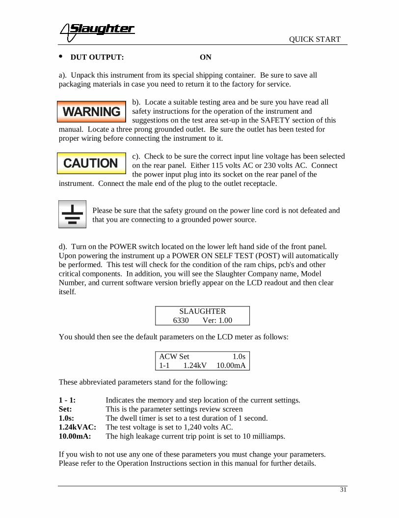
• DUT OUTPUT: ON
a). Unpack this instrument from its special shipping container. Be sure to save allpackaging materials in case you need to return it to the factory for service.
b). Locate a suitable testing area and be sure you have read allsafety instructions for the operation of the instrument andsuggestions on the test area set-up in the SAFETY section of this
manual. Locate a three prong grounded outlet. Be sure the outlet has been tested forproper wiring before connecting the instrument to it.
c). Check to be sure the correct input line voltage has been selectedon the rear panel. Either 115 volts AC or 230 volts AC. Connectthe power input plug into its socket on the rear panel of the
instrument. Connect the male end of the plug to the outlet receptacle.
Please be sure that the safety ground on the power line cord is not defeated andthat you are connecting to a grounded power source.
d). Turn on the POWER switch located on the lower left hand side of the front panel.Upon powering the instrument up a POWER ON SELF TEST (POST) will automaticallybe performed. This test will check for the condition of the ram chips, pcb's and othercritical components. In addition, you will see the Slaughter Company name, ModelNumber, and current software version briefly appear on the LCD readout and then clearitself.
You should then see the default parameters on the LCD meter as follows:
These abbreviated parameters stand for the following:
1 - 1: Indicates the memory and step location of the current settings.Set: This is the parameter settings review screen1.0s: The dwell timer is set to a test duration of 1 second.1.24kVAC: The test voltage is set to 1,240 volts AC.10.00mA: The high leakage current trip point is set to 10 milliamps.
If you wish to not use any one of these parameters you must change your parameters.Please refer to the Operation Instructions section in this manual for further details.
SLAUGHTER6330 Ver: 1.00
ACW Set 1.0s1-1 1.24kV 10.00mA

QUICK START
32
e). If the instrument defaults are acceptable then be sure to connect the appropriate testleads to the device under test (DUT) or test fixture. Be sure to connect this safety groundto a suitable known good ground before energizing this instrument and then connect thereturn lead first (black) to the test fixture or item followed by the high voltage output lead.
f). Please check your connections to be sure they are making good contact and that the teststation or area is clear of debris and other personnel.
DO NOT TOUCH THE DEVICE UNDER TEST ONCE THETEST HAS BEEN STARTED.
To initiate the test press the green TEST button on the front panel. This is a momentarybutton and does not need to be held in the pressed position during the test. The instrumentwill then cycle ON and begin the test using the defaults. If a failure occurs, you willHEAR an audible alarm. To stop the alarm you must depress the red button markedRESET. This will silence the alarm and reset the instrument to begin another test. ThisRESET button may also be used as a safety button to quickly ABORT a test and cut off theHIGH VOLTAGE.
When HIGH VOLTAGE is present, a RED flashing indicator located above theHV receptacle will remain flashing until the HIGH VOLTAGE is OFF. If thedevice under test PASSED the test then no audible alarm will sound. You willhear a brief BEEP to let you know the item was successfully tested and it
PASSED. In the case of a FAIL condition, the instrument will provide a memory of thetest condition results on the LCD display that will remain until the next test is initiated.Depressing the RESET button will reset the instrument alarm while keeping the last testresults on the display. Depressing the RESET button a second time will clear the display.

OPERATION
33
OPERATION INSTRUCTIONS FOR MODEL 6330
POWER UPCheck to be sure the correct input line voltage has been selected on the rear panel, either115 volts AC or 230 volts AC. Connect the power input plug into its socket on the rearpanel of the instrument. Connect the male end of the plug to the outlet receptacle.
Be sure that the safety ground on the power line cord is notdefeated and that you are connecting to a grounded power source.Connect the rear panel chassis ground for additional safety.
Turn on the POWER switch located on the lower left hand side of the front panel. Uponpowering the instrument up, a POWER ON SELF TEST (POST) will be automaticallyperformed. This test will check for the condition of the instrument’s critical components.In addition the display will show the following message, with the actual model numberand software version number:
The instrument will recall the last memory program that was active and the display willshow the parameters that were programmed into that memory. The instrument is nowready for operation.
SETUP PROCEDURE
1. Memory configurationThe model 6330 is equipped with 20 memory programs numbered 1 through 20. Eachmemory location contains 10 separate steps that can be connected sequentially to the nextconsecutive step. Only one test can be selected for each step.
Memory 1-10 Step 1-10ACDCIRGNDRUNLLT
To recall a memory program press the SET key, then press the Up (∧) or Down (∨) arrowkeys until the specific memory you wish to recall is displayed. Please see proceduresbelow for details. Pressing the EXIT key will activate selected memory position. To starta test, press the TEST button.
SLAUGHTER6330 Ver: 1.00

OPERATION
34
2. To select the Memory locationPress the SET key once. The blinking underscore symbol appears directly under digit thatrepresents memory location. The blinking cursor indicates that the parameter is beingedited. The display shows:
or
or
Use the Up (∧) or Down (∨) arrow keys to select memory locations 1 through 10.After selecting the memory, press the SET key to view the settings that have beenrecalled from memory or to make any changes to these settings. Once you have enteredall the test data such as test function and parameters of that function, as outlined in thebelow procedures, press the EXIT key to store any changes and return to the test mode.
3. To select the Step locationPress the SET key twice. The blinking underscore symbol appears directly under digitthat represents step location. The blinking cursor indicates that the parameter is beingedited. The display shows:
or
or
Use the Up (∧) or Down (∨) arrow keys to select step locations 1 through 20, then pressthe EXIT key to store the current setting and return to the test mode, or press the SET keyto advance to the next parameter.4. To set the test type
ACW MemoryXXX.XsXX-XX X.XXkV XX.XXmA
or DCW Memory XXX.XsXX-XX X.XXkV XX.XXmA
IR Memory XXX.XsXX-XX XXXXV XXXXM
or GND Memory XXX.XsXX-XX XXXm XX.XXA
RUN Memory XXX.XsXX-XX XXXV XX.XXA
or LLT Memory XXX.XsXX-XX XXXV XX.XXA
ACW Step XXX.XsXX-XX X.XXkV XX.XXmA
or DCW Step XXX.XsXX-XX X.XXkV XX.XXmA
IR StepXXX.XsXX-XX XXXXV XXXXM
or GND Step XXX.XsXX-XX XXXm XX.XXA
RUN Step XXX.XsXX-XX XXXV XX.XXA
or LLT Step XXX.XsXX-XX XXXV XX.XXA

OPERATION
35
To change the Test type on the model 6330, please press the SET key three times untilthe display shows:
or
or
Press the Up (∧) or Down (∨) arrow keys to toggle the test selection between AC, DC,IR, GND, RUN, and LLT modes; then press the EXIT key to store the setting and returnto the selected test mode or press the SET key if the parameters of the selected test needto be changed.
5. AC and DC dielectric withstand test modes setting (ACW/DCW)5.1. To set the Output VoltagePress the SET key until the display shows:
Use the Up (∧) or Down (∨) arrow keys to enter the desired test voltage, then press theSET key to advance to the next parameter or press the EXIT key to store the setting andreturn to the test mode. The maximum voltage which may be entered is 3.50kV AC or4.00kV DC. Any attempt to set the value outside these limits will cause the instrument tosignal an ERROR by producing two short beeps. Pressing the Down (∨) arrow key whenVoltage = 0.00kV also will cause the instrument to signal an ERROR by producing twoshort beeps.
5.2. To set the High Leakage Current LimitPress the SET key until the display shows:
Use the Up (∧) or Down (∨) arrow keys to enter the leakage current high limit setting,then press the SET key to advance to the next parameter or press the EXIT key to storethe setting and return to the test mode. The unit of measure is in milliamperes with20.00mA AC and 5.00mA DC as the maximum setting and with 0.00mA AC and DC asminimum setting. The High Leakage Current Limit will act as the high “trip point” forthe Hipot test. If the measured leakage current exceeds the value, the test will fail. Any
Mode = AC or Mode = DC
Mode = IR or Mode = GND
Mode = RUN or Mode = LLT
Voltage = X.XXkV
HI-Limit = XX.XXmA

OPERATION
36
attempt to set the value above this limit will cause the instrument to signal an ERROR byproducing two short beeps.
5.3. To set the Low Leakage Current LimitPress the SET key until the display shows:
Use the Up (∧) or Down (∨) arrow keys to enter the leakage current low limit setting,then press the SET key to advance to the next parameter or press the EXIT key to storethe setting and return to the test mode. The unit of measure is milliamperes with30.00mA AC and 5.00mA DC as the maximum setting and with 0.00mA AC and DC asthe minimum setting. The Low Leakage Current Limit will act as the low “trip point” forthe Hipot test. If the measured leakage current does not exceed this value, the test willfail. Any attempt to set the value below this limit will cause the instrument to signal anERROR by producing two short beeps.
5.4. To set the Ramp timePress the SET key until the display shows:
Use the Up (∧) or Down (∨) arrow keys to enter the ramp time setting, then press theSET key to advance to the next parameter or press the EXIT key to store the setting andreturn to the test mode. The minimum ramp time setting is 0.1 seconds, the maximumramp time setting is 999.9 seconds. Any attempt to set the values outside these limits willcause the instrument to signal an ERROR by producing two short beeps.
5.5. To set the Dwell timePress the SET key until the display shows:
Use the Up (∧) or Down (∨) arrow keys to enter the desired dwell time, then press theSET key to advance to the next parameter or press the EXIT key to store the setting andreturn to the test mode. If the dwell time is set to 0.0s, the instrument will operate in acontinuous ON mode when the TEST button is pressed. The instrument will stop whenthe DUT (Device Under Test) goes into failure or the RESET button is pressed. Theactual minimum dwell time setting is 0.2 seconds. The maximum dwell time setting is999.9 seconds. Any attempt to set the value more than 999.9s or less than 0.0s will causethe instrument to indicate an ERROR by producing two short beeps.
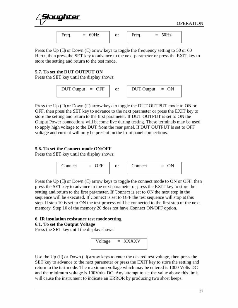
5.6. To set the Frequency 50/60 Hz (For AC mode only)Please press the SET key until the display shows:
LO-Limit = XX.XXmA
Ramp = XXX.Xs
Dwell = XXX.Xs
OPERATION
37
Press the Up (∧) or Down (∨) arrow keys to toggle the frequency setting to 50 or 60Hertz, then press the SET key to advance to the next parameter or press the EXIT key tostore the setting and return to the test mode.
5.7. To set the DUT OUTPUT ONPress the SET key until the display shows:
DUT Output = OFF or DUT Output = ON
Press the Up (∧) or Down (∨) arrow keys to toggle the DUT OUTPUT mode to ON orOFF, then press the SET key to advance to the next parameter or press the EXIT key tostore the setting and return to the first parameter. If DUT OUTPUT is set to ON theOutput Power connections will become live during testing. These terminals may be usedto apply high voltage to the DUT from the rear panel. If DUT OUTPUT is set to OFFvoltage and current will only be present on the front panel connections.
5.8. To set the Connect mode ON/OFFPress the SET key until the display shows:
Press the Up (∧) or Down (∨) arrow keys to toggle the connect mode to ON or OFF, thenpress the SET key to advance to the next parameter or press the EXIT key to store thesetting and return to the first parameter. If Connect is set to ON the next step in thesequence will be executed. If Connect is set to OFF the test sequence will stop at thisstep. If step 10 is set to ON the test process will be connected to the first step of the nextmemory. Step 10 of the memory 20 does not have Connect ON/OFF option.
6. IR insulation resistance test mode setting6.1. To set the Output VoltagePress the SET key until the display shows:
Use the Up (∧) or Down (∨) arrow keys to enter the desired test voltage, then press theSET key to advance to the next parameter or press the EXIT key to store the setting andreturn to the test mode. The maximum voltage which may be entered is 1000 Volts DCand the minimum voltage is 100Volts DC. Any attempt to set the value above this limitwill cause the instrument to indicate an ERROR by producing two short beeps.
Freq. = 60Hz or Freq. = 50Hz
Connect = OFF or Connect = ON
Voltage = XXXXV

OPERATION
38
6.2. To set the High Resistance LimitPress the SET key until the display shows:
Use the Up (∧) or Down (∨) arrow keys to enter the desired resistance high limit setting,then press the SET key to advance to the next parameter or press the EXIT key to storethe setting and return to the test mode. The unit of measure is in Megohms with 0MΩ -1000MΩ range of setting. Any attempt to set the value above this limit will cause theinstrument to indicate an ERROR by producing two short beeps. A measured value abovethe High Limit setting will result in a failure condition at the end of the Delay timesetting. A setting of 0MΩ disables the high limit feature.
6.3. To set the Low Resistance LimitPress the SET key until the display shows:
Use the Up (∧) or Down (∨) arrow keys to enter the desired resistance low limit setting,then press the SET key to advance to the next parameter or press the EXIT key to storethe setting and return to the test mode. The unit of measure is in Megohms with 1MΩ -1000MΩ range of setting. Any attempt to set the value below this limit will cause theinstrument to indicate an ERROR by producing two short beeps. A measured value belowthe Low Limit setting will result in a failure condition at the end of the Delay timesetting.
6.4. To set the Delay timePress the SET key until the display shows:
Use the Up (∧) or Down (∨) arrow keys to enter the desired delay time, then press theSET key to advance to the next parameter or press the EXIT key to store the setting andreturn to the test mode. If the delay time is set to 0.0s, the instrument will operate in acontinuous ON mode when the TEST button is pressed. The test will stop only when theRESET button is pressed or an OFL condition is detected. The actual minimum delaytime setting is 0.5 seconds. The maximum delay time setting is 999.9 seconds. Anyattempt to set the value more than 999.9s or less than 0.0s will cause the instrument toindicate an ERROR by producing two short beeps.
Note: The Delay timer in the IR mode differs from the Dwell timer in the Hipot mode. Ajudgment is not made until the Delay time has elapsed. In the Hipot mode a Pass / Failjudgment is made a soon as the leakage limits are exceeded. Therefore, when the Delaytime is set to zero Pass and Fail judgment or indications will not be made.
HI-Limit = XXXXMΩ
LO-Limit = XXXXMΩ
Delay = XXX.Xs

OPERATION
39
6.5. To set the DUT OUTPUT ONPress the SET key until the display shows:
DUT Output = OFF or DUT Output = ON
Press the Up (∧) or Down (∨) arrow keys to toggle the DUT OUTPUT mode to ON orOFF, then press the SET key to advance to the first parameter or press the EXIT key tostore the setting and return to the test mode. If DUT OUTPUT is set to ON the OutputPower connections will become live during testing. These terminals may be used to applyhigh voltage to the DUT from the rear panel. If DUT OUTPUT is set to OFF voltage andcurrent will only be present on the front panel connections.
6.6. To set the Connect mode ON/OFFPress the SET key until the display shows:
Press the Up (∧) or Down (∨) arrow keys to toggle the connect mode to ON or OFF, thenpress the SET key to advance to the next parameter or press the EXIT key to store thesetting and return to the test mode. If Connect is set to ON the next step in the sequencewill be executed. If Connect is set to OFF the test sequence will stop at this step. If step10 is set to ON the test process will be connected to the first step of the next memory.Step 10 of the memory 20 does not have Connect ON/OFF option.
7. GND Bond test mode setting7.1. To set the Output CurrentPress the SET key until the display shows:
Use the Up (∧) or Down (∨) arrow keys to enter the desired output current setting, thenpress the SET key to advance to the next parameter or press the EXIT key to store thecurrent setting and return to the test mode. The unit of measure is in amperes with 3A –30A range of setting. Any attempt to set the value outside these limits will cause theinstrument to indicate an ERROR message by producing two short beeps.
7.2. To set the High or Low LimitsPress the SET key until the display shows:
Connect = OFF or Connect = ON
Current = XX.XA
HI-Limit = XXXmΩ or LO-Limit = XXXmΩ

OPERATION
40
Use the Up (∧) or Down (∨) arrow keys to enter the desired value of the High or LowLimits resistance trip point then press the SET key to advance to the next parameter orpress the EXIT key to store the setting and return to the test mode. The unit of measure isin milliohms with a range of 0mΩ - 510mΩ at a current of 3.0A – 10.0A, 0mΩ - 200mΩat current of 10.1A – 25.0A, and 0mΩ – 150mΩ at current of 25.1A – 30.0A. Anyattempt to set the value outside this limits will cause the instrument to indicate anERROR message by producing two short beeps.
7.3. To set the Dwell timePress the SET key until the display shows:
Use the Up (∧) or Down (∨) arrow keys to enter the desired dwell time, then press theSET key to advance to the next parameter or press the EXIT key to store the setting andreturn to the test mode. If the dwell time is set to 0.0s, the instrument will operate in acontinuous ON mode when the TEST button is pressed. It will stop when the RESETbutton is pressed or the DUT goes into failure. The actual minimum dwell time setting is0.5 seconds. The maximum dwell time setting is 999.9 seconds. Any attempt to set thevalue more than 999.9s or less than 0.0s will cause the instrument to indicate andERROR by producing two short beeps.
7.4. To set the OffsetPress the SET key until the display shows:
Use the Up (∧) or Down (∨) arrow keys to adjust the setting of the offset manually, thenpress the SET key to advance to the next parameter or press the EXIT key to store thesetting and return to the test mode. To set the Offset automatically, press the TEST buttonwhen the test leads or test fixture is connected across the instrument Return and Currentoutputs. The instrument will measure the resistance that is present and enter this valueinto the Offset setting. This offset will be automatically subtracted from the actualresistance reading before the reading is displayed. The unit of measure is in milliohmswith a range of 0mΩ - 100mΩ. Any attempt to set the value outside these limits willcause the instrument to indicate and ERROR by producing two short beeps.
7.5. To set the FrequencyPress the SET key until the display shows:
Dwell = XXX.Xs
Offset = XXXmΩ TEST to Auto Set
Freq. = 60Hz or Freq. = 50Hz

OPERATION
41
Press the Up (∧) or Down (∨) arrow keys to toggle the frequency setting to 50 or 60Hertz, then press the SET key to advance to the next parameter or press the EXIT key tostore the frequency setting and return to the test mode.
7.6. To set the Connect mode ON/OFFPress the SET key until the display shows:
Press the Up (∧) or Down (∨) arrow keys to toggle the connect mode to ON or OFF, thenpress the SET key to advance to the next parameter or press the EXIT key to store thesetting and return to the test mode. If Connect is set to ON the next step in the sequencewill be executed. If Connect is set to OFF the test sequence will stop at this step. If step10 is set to ON the test process will be connected to the first step of the next memory.Step 10 of the memory 20 does not have Connect ON/OFF option.
8. Functional Run test mode setting8.1. To set the HI and LO Limits (Voltage)Press the SET key until the display shows:
Use the Up (∧) or Down (∨) arrow keys to enter the desired value of the High or LowLimits voltage trip point then press the SET key to advance to the next parameter or pressthe EXIT key to store the setting and return to the test mode. The unit of measure is 0 –277 VAC. Any attempt to set the value outside these limits will cause the instrument toindicate an ERROR by producing two short beeps.
8.2. To set the HI and LO Limits (Current)Press the SET key until the display shows:
Use the Up (∧) or Down (∨) arrow keys to enter the desired value of the High or LowLimits resistance trip point then press the SET key to advance to the next parameter orpress the EXIT key to store the setting and return to the test mode. The unit of measure is0 – 30 amps. Any attempt to set the value outside these limits will cause the instrument toindicate and ERROR by producing two short beeps.
8.3. To set the HI and LO Limits (Power)Press the SET key until the display shows:
Connect = OFF or Connect = ON
Volt-HI = XXX V or Volt-LO = XXX V
Amp-HI = XXX A or Amp-LO = XXX A
Power-HI = XXX W or Power-LO = XXX W

OPERATION
42
Use the Up (∧) or Down (∨) arrow keys to enter the desired value of the High or LowLimits resistance trip point then press the SET key to advance to the next parameter orpress the EXIT key to store the setting and return to the test mode. The unit of measure is0 – 8400 W. Any attempt to set the value outside these limits will cause the instrument toindicate an ERROR by producing two short beeps.
8.4. To set the HI and LO Limits (Power Factor)Press the SET key until the display shows:
Use the Up (∧) or Down (∨) arrow keys to enter the desired value of the High or LowLimits resistance trip point then press the SET key to advance to the next parameter orpress the EXIT key to store the setting and return to the test mode. Power factor may beset from 0 – 1. Power factor is indication of how resistive or reactive the DUT is. Apower factor of 1 corresponds to a purely resistive DUT whereas a power factor of 0corresponds to a purely reactive DUT. Any attempt to set the value outside these limitswill cause the instrument to indicate an ERROR by producing two short beeps.
8.5. To set the HI and LO Limits (Leakage Current)Press the SET key until the display shows:
Use the Up (∧) or Down (∨) arrow keys to enter the desired value of the High or LowLimits resistance trip point then press the SET key to advance to the next parameter orpress the EXIT key to store the setting and return to the test mode. The unit of measure is0 – 10.00 mA. Any attempt to set the value outside these limits will cause the instrumentto indicate an ERROR by producing two short beeps.
8.6. To set the Delay timePress the SET key until the display shows:
Use the Up (∧) or Down (∨) arrow keys to enter the desired delay time, then press theSET key to advance to the next parameter or press the EXIT key to store the setting andreturn to the test mode. If the delay time is set to 0.0s, the instrument will operate in acontinuous ON mode when the TEST button is pressed. The test will stop only when theRESET button is pressed or the OFL detected. The actual minimum delay time setting is0.5 seconds. The maximum delay time setting is 999.9 seconds. Any attempt to set thevalue more than 999.9s or less than 0.0s will cause the instrument to indicate an ERRORby producing two short beeps.
PF-HI = X.XXX or PF-LO = X.XXX
Leakage-HI = XX.XXmΑ or Leakage-LO = XX.XXmΑ
Delay = XXX.Xs

OPERATION
43
Note: The Delay timer in the Functional Run test mode differs from the Dwell timer inthe Hipot mode. A judgment is not made until the Delay time has elapsed. Therefore,when the Delay time is set to zero Pass and Fail judgment or indications will not bemade.
8.7. To set the Dwell timePress the SET key until the display shows:
Use the Up (∧) or Down (∨) arrow keys to enter the desired dwell time, then press theSET key to advance to the next parameter or press the EXIT key to store the setting andreturn to the test mode. If the dwell time is set to 0.0s, the instrument will operate in acontinuous ON mode when the TEST button is pressed. It will stop when the RESETbutton is pressed or the DUT goes into failure. The actual minimum dwell time setting is0.5 seconds. The maximum dwell time setting is 999.9 seconds. Any attempt to set thevalue more than 999.9s or less than 0.0s will cause the instrument to indicate an ERRORby producing two short beeps.
8.8. To set the Connect mode ON/OFFPress the SET key until the display shows:
Press the Up (∧) or Down (∨) arrow keys to toggle the connect mode to ON or OFF, thenpress the SET key to advance to the next parameter or press the EXIT key to store thesetting and return to the test mode. If Connect is set to ON the next step in the sequencewill be executed. If Connect is set to OFF the test sequence will stop at this step. If step10 is set to ON the test process will be connected to the first step of the next memory.Step 10 of the memory 20 does not have Connect ON/OFF option.9. Line Leakage test mode setting9.1. To set the HI and LO Limits (Voltage)Press the SET key until the display shows:
Please use the Up (∧) or Down (∨) arrow keys to enter the desired value of the High orLow Limits voltage trip point then press the SET key to advance to the next parameter orpress the EXIT key to store the setting and return to the test mode. The unit of measure is0 – 277 VAC. Any attempt to set the value outside these limits will cause the instrumentto indicate an ERROR by producing two short beeps.
9.2. To set the HI and LO Limits (Leakage Current)
Dwell = XXX.Xs
Connect = OFF or Connect = ON
Volt-HI = XXX V or Volt-LO = XXX V

OPERATION
44
Press the SET key until the display shows:
Please use theUp (∧) or Down (∨) arrow keys to enter the desired value of the High or Low Limitsresistance trip point then press the SET key to advance to the next parameter or press theEXIT key to store the setting and return to the test mode. The unit of measure is 0 – 10.00mA. Any attempt to set the value outside these limits will cause the instrument to indicateand ERROR by producing two short beeps.
9.3. To set the Line ConditionPress the SET key until the display shows:
Use the Up (∧) or Down (∨) arrow keys to select the desired Line Condition. Theavailable Line Conditions for the Line Leakage test are as follows:
Line 1 2 3 4 5 6 7 8Neutral OPEN OPEN OPEN OPEN CLOSE CLOSE CLOSE CLOSEReverse OFF ON OFF ON OFF ON OFF ONGround OPEN OPEN CLOSE CLOSE OPEN OPEN CLOSE CLOSE
As the Line Condition is set, the corresponding LED’s on the front panel will illuminate.These LED’s will signify which Line Condition is active for the test step. Press the SETkey to advance to the next parameter or press the EXIT key to store the setting and returnto the test mode.
9.4. To set the Measuring Device (MD)Press the SET key until display shows:
Use the Up (∧) or Down (∨) arrow keys to select the desired Measuring Device. Theavailable measuring devices are as follows:
Leakage-HI = XXXXuA or Leakage-LO =XXXXuA
Line = 1
MD = A

OPERATION
45
CrossReferenceLetter
Agency Specification Application
A UL544NP, UL484, UL923, UL471,UL867, UL697
Non-Patient Medical Equipment
B IEC60990 Fig4 U2, IEC 60950-1,IEC60335-1, IEC60598-1,IEC60065, IEC61010
IT Equipment, HouseholdAppliances, Luminaries,Laboratory Equipment
C UL2601-1, IEC60601-1 Medical Equipment
External User configurable User configurable
Frequency
Check
The Line Leakage test can beconfigured to verify the bandwidth ofthe leakage current “voltmeter.”
The selection is intended to beused for meter verification onlyand has no application for normaltesting.
Press the SET key to advance to the next parameter or press the EXIT key to store thesetting and return to the test mode.
Circuit DiagramsThe following diagrams show the equivalent circuit of the measuring devices. Leakagecurrent readings are generated by measuring the voltage drop across these networks anddividing by the equivalent DC resistance. The voltmeter is placed across the entirenetwork of the measuring device A. The voltmeter is placed across the points indicatedby the solid black dots on measuring devices B and C. The points are specified by theagencies that require a particular measuring device to meet their specification.

OPERATION
46
9.5. To set the Delay timePress the SET key until the display shows:
Use the Up (∧) or Down (∨) arrow keys to enter the desired delay time, then press theSET key to advance to the next parameter or press the EXIT key to store the setting andreturn to the test mode. If the delay time is set to 0.0s, the instrument will operate in acontinuous ON mode when the TEST button is pressed. The test will stop only when theRESET button is pressed or the OFL detected. The actual minimum delay time setting is
Delay = XXX.Xs

OPERATION
47
0.5 seconds. The maximum delay time setting is 999.9 seconds. Any attempt to set thevalue more than 999.9s or less than 0.0s will cause the instrument to indicate an ERRORby producing two short beeps.
Note: The Delay timer in the Line Leakage mode differs from the Dwell timer in theHipot mode. A judgment is not made until the Delay time has elapsed. Therefore, whenthe Delay time is set to zero Pass and Fail judgment or indications will not be made.
9.6. To set the Connect mode ON/OFFPress the SET key until the display shows:
Press the Up (∧) or Down (∨) arrow keys to toggle the connect mode to ON or OFF, thenpress the SET key to advance to the next parameter or press the EXIT key to store thesetting and return to the test mode. If Connect is set to ON the next step in the sequencewill be executed. If Connect is set to OFF the test sequence will stop at this step. If step10 is set to ON the test process will be connected to the first step of the next memory.Step 10 of the memory 20 does not have Connect ON/OFF option.
10. System Menu Parameters Setting10.1. To set the PLC Remote ON/OFFPress EXIT key once. The display shows:
Use the Up (∧) or Down (∨) arrow keys to change the PLC Remote setting, then press theSET key to advance to the next parameter or press the EXIT key to store the setting andreturn to the test mode. When the PLC Remote is turned ON the front panel TEST buttonis disabled and a test may only be started through the rear panel I/O. If you attempt tostart a test from the front panel TEST button when the PLC Remote function is turnedON the instrument will produce two short beeps and the following pop-up message willbe displayed:
Message will disappear after a few seconds or it can be cleared with the RESET button.
10.2. To set the Single Step ON/OFFPress EXIT key once then press the SET key until the display shows:
Connect = OFF or Connect = ON
PLC Remote = OFF or PLC Remote = ON
PLC Remote ON
Single Step = OFF or Single Step = ON

OPERATION
48
Use the Up (∧) or Down (∨) arrow keys to change the Single Step setting, then press theSET key to advance to the next parameter or press the EXIT key to store the setting andreturn to the test mode.This function is used to temporarily override the automatic connection feature. When theSingle Step function is ON the instrument will pause after each step is completed, eventhough the step Connect function is set to ON. To continue the test sequence, press theTEST button. Each time the TEST button is pressed the next connected step will execute.If you press the RESET button before completing all connected steps, it will return theinstrument to the original starting step. If a step fails and you wish to continue to the nextstep, do not press the RESET button, press the TEST button.
10.3. To set the Fail Stop ON/OFFPress EXIT key once then press the SET key until the display shows:
Use the Up (∧) or Down (∨) arrow keys to change the Fail Stop setting, then press theSET key to advance to the next parameter or press the EXIT key to store the setting andreturn to the test mode.
Fail Stop is a function that will stop a sequence of tests if a failure occurs. If this functionis turned OFF, the sequence of tests will continue to the end of the sequence regardless ofwhether or not a failure has occurred. If the Fail Stop is ON and a failure occurs duringthe test sequence, the red RESET button will light and a short alarm will sound but thesequence will continue to the end. At the end of the test sequence, the red RESET buttonwill light and alarm will sound indicating failure during the sequence. Pressing theRESET button will silence the alarm and reset the instrument.
10.4. Key Lock or Memory Lock settingThe model 6330 is equipped with two different levels of lockout selection. The firstselection is Key Lock. Within this selection, you can lockout all front panel controlfunctions except TEST and RESET. The second selection is Memory Lock and is used inconjunction with the Key Lock. Within this selection, you can lockout all front panelcontrol functions except TEST, RESET and memory select.
Use the following chart to set the Key Lock and Memory Lock for your application.
Fail Stop = OFF or Fail Stop = ON
Key Lock Memory Lock Accessible keysOFF OFF AllOFF ON AllON OFF TEST, RESET, and SET/Up-Down arrows
for memory selectionON ON TEST and RESET

OPERATION
49
To set the key Lock ON please press EXIT key once and then press the SET key until thedisplay shows:
Use the Up (∧) or Down (∨) arrow keys to change the Lock setting to ON, then press theSET key to advance to the next parameter or press the EXIT key to store the setting andreturn to the test mode. Once the EXIT key pressed key Lock function is activated.
Deactivation of the key Lock function is possible only from a power OFF state. Pleaseturn the POWER switch to the OFF position then press and hold the SET key and turn thepower ON. Then system menu (EXIT key) will be unlocked. Now you can press EXITkey once and then press the SET key until the display shows:
Use the Up (∧) or Down (∨) arrow keys to change the Lock setting to OFF, then press theSET key to advance to the next parameter or press the EXIT key to store the setting andreturn to the unlocked test mode.
Memory Lock function can be toggled when system unlocked or through the power OFFstate described above. Please press EXIT key once then press the SET key until thedisplay shows:
Use the Up (∧) or Down (∨) arrow keys to change the Memory Lock setting, then pressthe SET key to advance to the next parameter or press the EXIT key to store the settingand return to the test mode.
10.5. Alarm VolumePress EXIT key once then press the SET key until the display shows:
Use the Up (∧) or Down (∨) arrow keys to change the Alarm Volume setting, then pressthe SET key to advance to the next parameter or press the EXIT key to store the settingand return to the test mode. The Alarm Volume may be set from 0-9, with 0corresponding to OFF, 9 corresponding to the instrument alarm’s maximum volumesetting. If you attempt to increase or decrease the Alarm Volume outside of the limits willcause the instrument to indicate an ERROR by producing two short beeps.
Lock = OFF
Lock = ON
Memory Lock = OFF or Memory Lock = ON
Alarm Volume = 5

OPERATION
50
10.6. DUT-HV Set settingPress EXIT key once then press the SET key until the display shows:
Use the Up (∧) or Down (∨) arrow keys to change the DUT-HV setting, then press theSET key to advance to the next parameter or press the EXIT key to store the setting andreturn to the test mode.
The DUT-HV Set setting will enable or disable the DUT Output relay when an AC or DCHipot test or an Insulation Resistance test is performed. This is a global parameter andmust be enabled for high voltage to be present at the rear panel terminals during the test.There is also a DUT OUTPUT ON setting in each test’s parameter menu that must beenabled.
DUT-HV Setting = OFF or DUT-HV Setting = ON

OPERATION
51
OPERATING PROCEDURES
Instrument ConnectionsIf the instruments defaults are acceptable then be sure to connect the appropriate testleads to the device under test (DUT) or test fixture. Be sure to connect the safety ground(on the rear panel) to a suitable known good ground before energizing this instrument.Connect the return lead to the test fixture or the DUT first, followed by the high voltagelead.
Check your connections to be sure they are making good contact and that the test stationor area is clear of debris or other personnel.
DO NOT TOUCH THE DEVICE UNDER TEST ONCETHE TEST HAS BEEN STARTED.
DisplayFollow the previously stated setup procedures to set the desired parameters. The displaywill show the Dielectric Withstand test settings, the Insulation Resistance test settings,the Ground Bond test settings, the Functional Run test settings or the Line Leakage testsettings depending on what has been selected.
The underscore character may be displayed after the step number, i.e. X – X_. Thisindicates that there is another configured test step that will execute after the displayedsetup has completed. To view the next test setup please press the SET key twice thenpress the Up arrow key. To return to the previous test please press the Down arrow keyand then EXIT key to return to the test mode.
1. AC or DC Dielectric Withstand Test Mode1.1. To initiate a test, press the TEST button on the front panel. The red High VoltageArrow indicator will flash and the display will immediately show:
or
DCW Set XXX.XsXX-XX X.XXkV XX.XXmA then
DCW Dwell XXX.XsXX-XX X.XXkV XX.XXmA
The instrument will continue to output the desired voltage for the duration of the selectedRamp and Dwell times.
1.2. If the DUT has passed the test, the green TEST button will illuminate and a shortaudible beep tone will activate. The display will show:
ACW Set XXX.XsXX-XX X.XXkV XX.XXmA
then ACW Dwell XXX.XsXX-XX X.XXkV XX.XXmA

OPERATION
52
ACW Pass XXX.XsXX-XX X.XXkV XX.XXmA
or DCW Pass XXX.XsXX-XX X.XXkV XX.XXmA
The instrument is ready to perform another test.
1.3. If the operator elects to abort a test in process this can be accomplished by pressingthe RESET button at anytime. The instrument will stop the test process immediately andthe display will show:
ACW Abort XXX.XsXX-XX X.XXkV XX.XXmA
or DCW Abort XXX.XsXX-XX X.XXkV XX.XXmA
Please press the TEST button to initiate another test.
1.4. If the leakage current exceeds the high limit setting, but does not exceed the meteringrange, the red RESET button will illuminate and an alarm will activate. The display willshow:
ACW HI-Limit XXX.XsXX-XX X.XXkV XX.XXmA
or DCW HI-Limit XXX.XsXX-XX X.XXkV XX.XXmA
To stop the alarm, please press the RESET button once. The alarm will stop and thedisplay will retain the failure information. The instrument is now ready for the next test.If the RESET button is pressed again, the failure information will be cleared and thedisplay will indicate the setting data of the test.
1.5. If the leakage current does not exceed the low limit setting, the red RESET buttonwill illuminate and an alarm will activate. The display will indicate:
ACW LO-Limit XXX.XsXX-XX X.XXkV XX.XXmA or
DCW LO-Limit XXX.XsXX-XX X.XXkV XX.XXmA
To stop the alarm, please press the RESET button once. The alarm will stop and thedisplay will retain the failure information. The instrument is now ready for the next test.If the RESET button is pressed again, the failure information will be cleared and thedisplay will indicate the setting data of the test.
1.6. If there is a short circuit in the DUT during the test, the red RESET button willilluminate and an alarm will activate. The display will show:
ACW OFL XXX.XsXX-XX X.XXkV >30.0mA or
DCW OFL XXX.XsXX-XX X.XXkV >5.00mA
To stop the alarm, please press the RESET button once. The alarm will stop and thedisplay will retain the failure information. The instrument is now ready for the next test.If the RESET button is pressed again, the failure information will be cleared and thedisplay will indicate the setting data of the test.

OPERATION
53
2. Insulation Resistance Test Mode2.1. To initiate a test press the TEST button on the front panel. The red High VoltageArrow indicator will flash and the display will immediately show:
IR Set XXX.XsXX-XX XXXXV XXXXM
then IR DelayXXX.XsXX-XX XXXXVXXXXM
2.2. If the DUT has passed the test, the green TEST button will illuminate and a shortaudible beep will be activated. The display will show:
IR Pass XXX.XsXX-XX XXXXVXXXXM
The instrument is ready to perform another test.
2.3. If the operator elects to abort a test in process this can be accomplished by pressingthe RESET button at anytime. The instrument will stop the test process immediately andthe display will show:
IR Abort XXX.XsXX-XX XXXXVXXXXM
Press the TEST button to initiate another test.
2.4. If the insulation resistance exceeds the high limit setting, the red RESET button willilluminate and an alarm will activate. The display will show:
IR HI-LimitXXX.XsXX-XX XXXXVXXXXM
To stop the alarm, please press the RESET button once. The alarm will stop and thedisplay will retain the failure information. The instrument is now ready for the next test.If the RESET button is pressed again, the failure information on the screen will becleared and the display will indicate the setting data of the previous test.

OPERATION
54
2.5. If the insulation resistance does not exceed the low limit setting and is within themetering range the red RESET button will illuminate and an alarm will activate. Thedisplay will show:
IR LO-LimitXXX.XsXX-XX XXXXVXXXXM
To stop the alarm, please press the RESET button once. The alarm will stop and thedisplay will retain the failure information. The instrument is now ready for the next test.If the RESET button is pressed again, the failure information on the screen will becleared and the display will indicate the setting data of the test.
3. Ground Bond Test Mode3.1. To initiate a test press the TEST button on the front panel. The instrument willcontinue to output the desired current for the duration of the selected dwell time. Thedisplay will indicate:
GND Set XXX.XsXX-XX XX.XA XXXm
then GND Dwell XXX.XsXX-XX XX.XA XXXm
3.2. If the DUT has passed the test, the green TEST button will illuminate and a shortaudible beep will be activate. The display will indicate:
The instrument is ready to perform another test.
3.3. If the operator elects to abort a test in process this can be accomplished by pressingthe RESET button at anytime. The instrument will stop the test process immediately. Thedisplay will indicate:
Please press the TEST button to initiate another test
GND Pass XXX.XsXX-XX XX.XA XXXm
GND Abort XXX.XsXX-XX XX.XA XXXm

OPERATION
55
3.4. If the resistance exceeds the metering range, the red RESET button will illuminateand the alarm will be activate. The display will show:
If current3.0 – 10.0A
If current10.1 – 25.0A
If current25.1 – 30.0A
To stop the alarm, press the RESET button once. The alarm will stop and the display willretain the failure information. The instrument is now ready for the next test. If the RESETbutton is pressed again, the failure information will be cleared and the display willindicate the setting data of the test. The display will show:
3.5. If the resistance exceeds the high limit trip setting but does not exceed the meteringrange, the red RESET button will illuminate and the alarm will be activated. The displaywill show:
To stop the alarm, press the RESET button once. The alarm will stop and the display willretain the failure information. The instrument is now ready for the next test. If the RESETbutton is pressed again, the failure information will be cleared and the display willindicate the setting data of the test.
3.6. If the resistance does not exceed the low limit setting, the red RESET button willilluminate and the alarm will be activated. The display will show:
To stop the alarm, press the RESET button once. The alarm will stop and the display willretain the failure information. The instrument is now ready for the next test. If the RESETbutton is pressed again, the failure information will be cleared and the display willindicate the setting data of the test.
4. Functional Run test mode4.1. To initiate a test, press the TEST button on the front panel. The display willimmediately show:
X – X HI-Lmt XXX.XsXX.XA GND >510mΩ
X – X HI-Lmt XXX.XsXX.XA GND >200mΩ
X – X HI-Lmt XXX.XsXX.XA GND >150mΩ
GND Set XXX.XsXX-XX XX.XA XXXm
GND Hi-Limit XXX.XsXX-XX XX.XA XXXm
GND LO-Limit XXX.XsXX-XX XX.XA XXXm

OPERATION
56
The instrument will continue to output the desired voltage for the duration of the selectedDelay and Dwell times. Use the Up (∧) or Down (∨) arrow keys to bring up an alternatedisplay screen while the test is running. The alternate display screen will show:
4.2. If the DUT has passed the test, the greenTEST button will illuminate and a short audible beep will activate. The display willshow:
Use the Up (∧) or Down (∨) arrow keys to bring up an alternate display screen after thetest has completed. The alternate display will show:
The instrument is ready to perform another test.
4.3. If the operator elects to abort a test in process this can be accomplished by pressingthe RESET button at anytime. The instrument will stop the test process immediately andthe display will show:
Please press the TEST button to initiate another test.
4.4. If the DUT input voltage exceeds the high limit setting or does not exceed the lowlimit setting, the red RESET button will illuminate and an alarm will activate. Thedisplay will show:
RUN Volt-HI XXX.XsXX-XX XX.XV XX.XA
or RUN Volt-LOXXX.XsXX-XX XX.XV XX.XA
To stop the alarm, press the RESET button once. The alarm will stop and the display willretain the failure information. The instrument is now ready for the next test. If the RESETbutton is pressed again, the failure information will be cleared and the display willindicate the setting data of the test.
RUN Set XXX.XsXX-XX XX.XV XX.XA then
RUN Delay XXX.XsXX-XX XX.XV XX.XA
RUN Dwell X.XX mAXX.XX XWX.XXXPF
RUN Pass XXX.XsXX-XX XX.XV XX.XA
RUN Pass X.XX mAXX-XX XW X.XXXPF
RUN Abort XXX.XsXX-XX XX.XV XX.XA
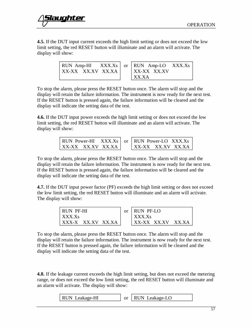
OPERATION
57
4.5. If the DUT input current exceeds the high limit setting or does not exceed the lowlimit setting, the red RESET button will illuminate and an alarm will activate. Thedisplay will show:
RUN Amp-HI XXX.XsXX-XX XX.XV XX.XA
or RUN Amp-LO XXX.XsXX-XX XX.XVXX.XA
To stop the alarm, please press the RESET button once. The alarm will stop and thedisplay will retain the failure information. The instrument is now ready for the next test.If the RESET button is pressed again, the failure information will be cleared and thedisplay will indicate the setting data of the test.
4.6. If the DUT input power exceeds the high limit setting or does not exceed the lowlimit setting, the red RESET button will illuminate and an alarm will activate. Thedisplay will show:
RUN Power-HI XXX.XsXX-XX XX.XV XX.XA
or RUN Power-LO XXX.XsXX-XX XX.XV XX.XA
To stop the alarm, please press the RESET button once. The alarm will stop and thedisplay will retain the failure information. The instrument is now ready for the next test.If the RESET button is pressed again, the failure information will be cleared and thedisplay will indicate the setting data of the test.
4.7. If the DUT input power factor (PF) exceeds the high limit setting or does not exceedthe low limit setting, the red RESET button will illuminate and an alarm will activate.The display will show:
RUN PF-HIXXX.XsXXX-X XX.XV XX.XA
or RUN PF-LOXXX.XsXX-XX XX.XV XX.XA
To stop the alarm, please press the RESET button once. The alarm will stop and thedisplay will retain the failure information. The instrument is now ready for the next test.If the RESET button is pressed again, the failure information will be cleared and thedisplay will indicate the setting data of the test.
4.8. If the leakage current exceeds the high limit setting, but does not exceed the meteringrange, or does not exceed the low limit setting, the red RESET button will illuminate andan alarm will activate. The display will show:
RUN Leakage-HI or RUN Leakage-LO

OPERATION
58
XXX.XsXX-XX XX.XV XX.XA
XXX.XsXX-XX XX.XV XX.XA
To stop the alarm, please press the RESET button once. The alarm will stop and thedisplay will retain the failure information. The instrument is now ready for the next test.If the RESET button is pressed again, the failure information will be cleared and thedisplay will indicate the setting data of the test.
4.9. If there is a short circuit in the DUT causing excessive line current during the test,the red RESET button will illuminate and an alarm will activate. The display will show:
RUN Line-OC XXX.XsXX-XX XX.XV XX.XA
To stop the alarm, please press the RESET button once. The alarm will stop and thedisplay will retain the failure information. The instrument is now ready for the next test.If the RESET button is pressed again, the failure information will be cleared and thedisplay will indicate the setting data of the test.
4.10. If there is a short circuit in the DUT causing excessive leakage current during thetest, the red RESET button will illuminate and an alarm will activate. The display willshow:
RUN Leak-OCXXX.XsXX-XX XX.XV XX.XA
To stop the alarm, please press the RESET button once. The alarm will stop and thedisplay will retain the failure information. The instrument is now ready for the next test.If the RESET button is pressed again, the failure information will be cleared and thedisplay will indicate the setting data of the test.
5. Line Leakage test mode5.1. To initiate a test, press the TEST button on the front panel. The display willimmediately show:
LLT Set XXX.XsXX-XX XXX.XV XXXXuA then
LLT Delay XXX.XsXX-XX XXX.XV XXXXuA
The instrument will continue to output the desired voltage for the duration of the selectedDelay time.
5.2. If the DUT has passed the test, the green TEST button will illuminate and a shortaudible beep will activate. The display will show:
LLT Pass XXX.Xs

OPERATION
59
XX-XX XXX.XVXXXXuA
The instrument is ready to perform another test.
5.3. If the operator elects to abort a test in process this can be accomplished by pressingthe RESET button at anytime. The instrument will stop the test process immediately andthe display will show:
LLT AbortXXX.XsXX-XX XXX.XVXXXXuA
Please press the TEST button to initiate another test.
5.4. If the DUT input voltage exceeds the high limit setting or does not exceed the lowlimit setting, the red RESET button will illuminate and an alarm will activate. Thedisplay will show:
LLT Volt-HIXXX.XsXX-XX XX.XVXXXXuA
or LLT Volt-LOXXX.XsXX-XX XX.XV XXXXuA
To stop the alarm, please press the RESET button once. The alarm will stop and thedisplay will retain the failure information. The instrument is now ready for the next test.If the RESET button is pressed again, the failure information will be cleared and thedisplay will indicate the setting data of the test.
5.5. If the DUT leakage current exceeds the high limit setting or does not exceed the lowlimit setting, the red RESET button will illuminate and an alarm will activate. Thedisplay will show:
LLT Leakage-HIXXX.XsXX-XX XX.XV XXXXuA
or LLT Leakage-LOXXX.XsXX-XX XX.XV XXXXuA
To stop the alarm, please press the RESET button once. The alarm will stop and thedisplay will retain the failure information. The instrument is now ready for the next test.If the RESET button is pressed again, the failure information will be cleared and thedisplay will indicate the setting data of the test.

OPERATION
60
5.6. If there is a short circuit in the DUT during the test, the red RESET button willilluminate and an alarm will activate. The display will show:
LLT Line-OCXXX.XsXX-XX XX.XV XXXXuA
To stop the alarm, please press the RESET button once. The alarm will stop and thedisplay will retain the failure information. The instrument is now ready for the next test.If the RESET button is pressed again, the failure information will be cleared and thedisplay will indicate the setting data of the test.
5.7. If there is a short circuit in the DUT during the test, the red RESET button willilluminate and an alarm will activate. The display will show:
LLT Leak-OC XXX.XsXX-XX XX.XV XXXXuA
To stop the alarm, please press the RESET button once. The alarm will stop and thedisplay will retain the failure information. The instrument is now ready for the next test.If the RESET button is pressed again, the failure information will be cleared and thedisplay will indicate the setting data of the test.
5.8. If the DUT Input Voltage is wired incorrectly the red RESET button will illuminateand an alarm will activate. The display will show:
LLT Neutral-V XXX.XsXX-XX XX.XV XXXXuA
To stop the alarm, please press the RESET button once. The alarm will stop and thedisplay will retain the failure information. The instrument is now ready for the next test.If the RESET button is pressed again, the failure information will be cleared and thedisplay will indicate the setting data of the test.
6. Reviewing Test Result in multi-step testsThe test results from the memories that have been executed can be reviewed by pressingthe Up (∧) or Down (∨) arrow keys. Successive key presses will continue advancing tothe next result. The results of the last step in the process will be followed by the first step.Results can be reviewed at any time before the next test is executed. All results arecleared at the start of the next test cycle.
7. Output ErrorThis message appears on the display if the instrument’s output reading does not match thesetting. When the instrument has an output problem and the TEST button is pressed, theOutput Error screen will appear as follows:

OPERATION
61
The RESET button is not active in this situation. Only the EXIT key will allow you toreturn to the test mode. When the EXIT key is pressed the instrument will continue withits normal failure indication process. The failure light and alarm can be cleared bypressing the RESET button. If Output Error occurs please call the Slaughter CompanyCustomer Support Center at 1-800-504-0055 for assistance.
8. Fatal ErrorIf the instrument has a Fatal Error failure then the following screen will appear:
None of the buttons and keys will be active in this situation. This type of failurepermanently locks the instrument in the Fatal Error mode and requires that the instrumentbe serviced by the Slaughter Company. The customer should contact the SlaughterCompany Customer Support Center at 1-800-504-0055 to receive further instruction.
The following Fatal Error identification numbers will represent the type of the failure thathas occurred:
FATAL ERROR 9001 will appear on the display, if the instrument has a recognizableinternal component failure.
FATAL ERROR 9002 will appear on the display, if the instrument’s System data or theModel/Option data are corrupted and do not match the setting.
FATAL ERROR 9003 will appear on the display, if the instrument’s Calibration data iscorrupted.
FATAL ERROR 9004 will appear on the display, if the instrument has an internal datatransfer error.
OUTPUT ERROR! EXIT to continue
FATAL ERROR 900X Call 18005040055

OPERATION
62
CONNECTION OF REMOTE I/O
Two 9-pin “D” type connectors are mounted on the rear panel that provides REMOTE-INPUT-OUTPUT control and information. These connectors mate with standard 9 pinD-sub-miniature connector provided by the user. The output mates to a male (plug)connector while the input mates to a female (receptacle) connector. For bestperformance, a shielded cable should be used. To avoid ground loops the shield shouldnot be grounded at both ends of the cable. Suggested AMP part numbers forinterconnecting to the Remote I/O are shown below:
205204-4 PLUG SHELL WITH GROUND INDENTS205203-3 RECEPTACLE SHELL745254-7 CRIMP SNAP-IN PIN CONTACT (for plug)745253-7 CRIMP SNAP-IN SOCKET CONTACT (for receptacle)745171-1 SHIELDED CABLE CLAMP (for either plug or receptacle)747784-3 JACKSCREW SET (2)
Remote Interface Rear Panel
SIGNAL OUTPUTS ON REMOTE I/OThe rear panel connector provides output signals to remotely monitor PASS, FAIL, andPROCESSING conditions. These signals are provided by three normally open internalrelays that switch on to indicate the current condition of the tester. These are normallyopen free contacts and will not provide any voltage or current. The ratings of thecontacts are 1A / 250 VAC ( 0.5 ADC ). Below is a listing that indicates what conditionsactivate each pin. When a terminal becomes active, the relay closes thereby allowing theexternal voltage to operate an external device.
Pins 1 and 2 provide the PASS signal.Pins 3 and 4 provide the FAIL signal.Pins 5 and 6 provide the PROCESSING signal.
BIT 2
C OM M O NBIT 1
6 9
SIGNAL INPUT
1
BIT 3
5
INTER LO CK
TESTRE SET
SIGNAL OUTPUT
PROCESSING
5
9
FAIL
1
6
PASS

OPERATION
63
The following describes how the relays operate for each test condition.
PROCESSING - The relay contact closes the connection between pin (5) and pin (6)while the instrument is performing a test. The connection is opened at the end of the test.
PASS - The relay contact closes the connection between pin (1) and pin (2) afterdetecting that the item under test passed all tests. The connection is opened when thenext test is initiated or the reset function is activated.
FAIL - The relay contact closes the connection between pin (3) and pin (4) after detectingthat the item under test failed any test. The connection is opened when the next test isinitiated or the reset function activated.
SIGNAL INPUTS OF REMOTE I/O and PROGRAMMED TESTSThe model 6330 remote connector enables remote operation of the TEST, RESET, andREMOTE INTERLOCK functions, and allows the operator to select one of 6preprogrammed tests.
When the PLC Remote mode is ON, the instrument will respond to simple switch or relaycontacts closures. A normally open momentary switch can then be wired across pins 3and 5 to allow remote operation of the TEST function. When the PLC Remote function isON the TEST button on the front panel will be disabled to prevent a test from beingactivated through this button. If you attempt to start a test from the front panel TESTbutton and the PLC Remote function is turned “ON”, a pop-up message will bedisplayed. The pop-up message will appear as follows
A normally open momentary switch can also be wired across pins 2 and 5 to allowremote operation of the RESET function. For safety, the front panel RESET buttonremains active even when a remote reset switch is connected so that high voltage can beshut down from either location.
The Remote Test Select function gives the user the capability to quickly changeparameters and initiate a test remotely. Six pre-programmed tests can be accessed byconnecting pins 1, 8, and 9 to the common pin 7, in different combinations. The memoryselect bits should be set simultaneously and remain set for a minimum of 20ms toguarantee that the correct memory will be selected. However, the memory select bitsmay be set in sequential manner, provided that the time delay between each bit is lessthan 4ms. When the desired bit pattern has been established it should remain set for aminimum of 20ms to guarantee that the correct memory will be selected. The RemoteTests Select Truth Table (binary) shows the different combinations of momentaryswitch (relay) closures, and which memory programs that will be selected as the result. Itmay be necessary to "OR" the momentary switches (relay contacts) to prevent incorrectprogram selection due to timing errors.
Remote Tests Select Truth Table
PLC Remote ON

OPERATION
64
BIT 3 BIT 2 BIT 1 TEST #0 0 1 010 1 0 020 1 1 031 0 0 041 0 1 051 1 0 06
Where: 1 = Momentary Contact closure between BIT and COMMON0 = NO Contact closure between BIT and COMMON
Activating test program functions through the remote connectorselects the memory and starts the test that is pre-programmedinto that memory.
Do not connect voltage or current to the signal inputs. Applyingvoltage to the signal input could result in damage to the controlcircuitry.
REMOTE INTERLOCKThe model 6330 is equipped with a featured referred to as “Remote Interlock”. RemoteInterlock is a feature that utilizes a set of closed contacts to enable the instruments output.In other words, if the Interlock contacts open, the output of the instrument will bedisabled. Remote Interlock could also be referred to as a remote system lockout, utilizing“Fail When Open” logic. If the Interlock contacts are open and the TEST button ispushed, a pop-up message will be displayed on the screen for few seconds. The messagewill appear as follows:
If the Interlock contacts are opened during a test, the pop-up message will be displayedand the test will abort.
The hardware and software have been configured to provide the interlock connections onpins 4 and 5 of the Remote Interface, Signal Input port. This reset scheme is designed foruse with an external safety interlock device that utilizes a "Fail-When-Open"configuration on its output interface The instrument can still be used without the externalinterlock device as long as the Interlock Connector (P/N # 99-10040-01 provided withunit) is plugged into the Remote Interface, Signal Input port. If there is nothingconnected to the Remote Interface, Signal Input port to provide a connection to theinterlock, the instrument will not perform tests.
Interlock Open

OPERATION
65
INSTRUMENT CONNECTIONS
The Slaughter 6330 comes with test leads to perform all necessary safety tests. Thefollowing test leads are included with the instrument:
Part Number Description99-10467-01 Adapter Box99-10457-01 LLT CASE LEAD99-10468-01 LLT GROUND
LEAD99-10009-01 GND BND
OUTPUT99-10008-01 RETURN LEAD99-10469-01 LLT INPUT LINE99-10470-01 LLT INPUT
NEUTRAL99-10471-01 LLT OUTPUT
LINE99-10472-01 LLT OUTPUT
NEUTRAL102-055-913 High Voltage Cable
Functional Run/Line Leakage stand-alone test lead connectionsIn order to perform a Line Leakage and/or Functional Run test, an external power supplymust be used to provide power to the device under test.
The power supply must be an unbalanced, single phase 0-277VAC supply. Using a balanced supply may cause damage to theinstrument or operator.
Provided with the instrument are two 10 AWG input power leads (terminated on one end)that may be connected to the 6330’s DUT Power In screw-mount terminals (line andneutral). These leads are left un-terminated at the other end and should be connected tothe outputs of the power supply. The 10 AWG input power leads may be used forapplications in which the DUT requires more than 20 Amps of input current.
Provided with the instrument are two 10 AWG output power leads (terminated on oneend) that may be used to connect to the 6330’s DUT Power Out screw-mount terminals(line and neutral). These leads are left un-terminated at the other end and should beconnected to the device under test for applications that require more than 20 Amps ofinput current

OPERATION
66
The following diagram shows how to connect the stand alone test leads to the 6330 and tothe device under test:
99-10471-01 LINE99-10472-01 NEUTRAL
99-10468-01 EARTH GROUND
99-10457-01
LINE CONNECTIONS
DUTCHASSIS
DUT I.E. AC FAN
99-10470-01 NEUTRAL99-10469-01 LINE
AC SOURCE0-277VAC
YOURTEST
FIXTURE
Adapter Box connectionsIn addition to the stand-alone test leads, the instrument also comes with an adapter box.The adapter box allows the user an easy way to connect an item that is terminated in athree-prong line cord. Note: the adapter box may only be connected to the rear panel ofthe 6330. The following diagram shows how to connect the adapter box to the 6330 andto the device under test.
LINE
NEUTRAL
99-10467-01
99-10457-01
LINECORD
DUTCHASSIS
DUT I.E. AC FAN
CAUTIONHIGH VOLTAGE
5KVAC MAX.6KVDC MAX.
20A MAX. LINE CURRENT.
NL
EARTH GROUND99-10469-01 LINE99-10470-01 NEUTRAL
AC SOURCE0-277VAC

OPERATION
67
The adapter box (P/N 99-10467-01) may be used to performHipot, Ground Bond, Insulation Resistance, Functional Run, andLine Leakage tests. The adapter box is rated for a maximum of
20 Amps of input current. If current levels greater than 20 Amps are needed for either theFunctional Run test or the Line Leakage test, the stand alone test leads must be used.

REMOTE BUS INTERFACE: RS-232
68
Bus Remote Interface: RS-232This section provides information on the proper use and configuration of bus remoteinterface. The RS-232 remote interface is optional on all 6330 models. Please see theOPTIONS section of the manual for details.
RS-232 InterfaceThis interface provides all of the control commands and parameter setting commands. Allcommands can be found in the command list of this manual.
The RS-232 cabling should be configured as follows for a 9-pin serial port interface:
The COM port should have the following configuration. 9600 baud, 8 data bits, 1 stopbit, no parity. This interface does not support XON/XOFF protocol or any hardwarehandshaking. The controller should be configured to ignore the handshaking lines DTR(pin 4), DSR (pin 6), CTS (pin 8) and RTS (pin 7). If the port cannot be configuredthrough software to ignore the lines then the handshake lines should be jumpered togetherin two different sets. Pins 4 and 6 jumpered together and pins 7 and 8 jumpered togetherat the controller end of the cable.
When sending command over the RS232 bus, the instrument will send a response stringof 06 hex or 6 decimal, the Acknowledge (ACK) ASCII control code if the transfer wasrecognized and completed by the instrument. If there is an error with the command stringthat is sent, the instrument will respond with 15 hex or 21 decimal, the Not Acknowledge(NAK) ASCII control code. The ACK or NAK response allows for softwarehandshaking, to monitor and control data flow. When requesting data from theinstrument, it will automatically send the data back to the controller input buffer. Thecontroller input buffer will accumulate data being sent from the instrument including theACK and NAK response strings, until it has been read by the controller.
RS-232 Interface Command ListThe RS-232 bus will automatically send any response back to the controller's inputbuffer. Note that the commands are case sensitive and must be typed in capital letters.Each command string should be terminated by the ASCII control code, New Line <NL>,or OAh.
The following conventions are used to describe the commands syntax for the 6330.Braces ( ) enclose each parameter for a command string. Triangle brackets (< >)indicate that you must substitute a value for the enclosed parameter. The Pipe ( | ) is used
Instrument RS-232 Port PC / Bus Controller
2
3
5
2
3
5
TD
RD
TD
RD
SIGGND
SIGGND

REMOTE BUS INTERFACE: RS-232
69
to separate different parameter options for a command. The command and the parameterdata must be separated with a space. All commands that end with a question mark (?) arequery commands and require an IEEE-488 read command to retrieve the data from thedevice's output buffer.
Test Execution CommandsThe following commands are used to control actual output voltage and current from theinstrument. Please observe all safety precautions.
Command DescriptionTEST Execute a TestRESET Abort a Test in Process or Reset FailuresSAO Set Auto Offset
TESTStarts the test sequence at the selected step loaded into memory (RAM).
RESETStop or abort a test. Also used to reset a latched failure condition.
SAOSet the offset for the Ground bond test. The cables and any test fixture should beconnected before executing the command. This command will perform an actual test andall safety precautions should be observed when using this command.
File Editing Commands and Companion QueriesThe following commands are used to create or modify Test Setup Files.
Command Description ValueFL <file number>FL?
File Load file number = 1-20
SS <step number>SS?
Step Select step number = 1-10
SAA Step Add ACW testSAD Step Add DCW testSAI Step Add IR testSAG Step Add GND testSAR Step Add RUN testSAL Step Add LLT test
FL <file number>Load a file from non-volatile memory into random access memory RAM.
SS <step number>Selects the active selected step to load into RAM. The step must first be selected beforeany specific parameters can be edited.

REMOTE BUS INTERFACE: RS-232
70
The parameter values should use complete text and not use the coded values that areassociated with the individual parameter setting commands. Such as "ON" and "OFF"and any toggle field that use words or phrases like "OPEN", "CLOSE". The LS?companion command will also list all parameters in complete text as they appear on thesetting screen.
ACW DCW IR1 Voltage Voltage Voltage2 Max Limit Max Limit Max Limit3 Min Limit Min Limit Min Limit4 Ramp Up Ramp Up Delay5 Dwell Dwell DUT Output
(ON/OFF)6 Frequency DUT Output
(ON/OFF)Connect (ON/OFF)
7 DUT Output (ON/OFF) Connect (ON/OFF)8 Connect (ON/OFF)
GND RUN LLT1 Current Voltage-HI Voltage-HI2 HI-Limit Voltage-LO Voltage-LO3 LO-Limit Amp-HI Leakage-HI4 Dwell Amp-LO Leakage-LO5 Offset Power-HI Delay Time6 Frequency Power-LO Line (Neutral,Polarity,Ground)7 Connect
(ON/OFF)PF-HI Meas. Device
(UL544NP/UL484/UL923,UL471,UL867,UL697,IEC60990 Fig4 U2,IEC60950-1,IEC60335-1,IEC60598-1,IEC60065,IEC61010,UL2601-
1,IEC60601-1,External)8 PF-LO Delay Time
9 Leakage-HI Connect10 Leakage-LO11 Delay12 Dwell13 Connect
(ON/OFF)
Test Parameter Editing CommandsThese commands are used to modify the test parameter within each step. Thesecommands require a parameter value to be included with the command. The companionquery command will read the parameter. The writing of the parameter requires that theunit not be included with the value, only the numeric value should be included with thecommand. Also when the query commands are used the response will not include theunits characters. Many of the commands will function the same way for multiple test

REMOTE BUS INTERFACE: RS-232
71
types however the input range may be different and therefore used a different possible setof values.
Command Name TestTypes
Value
ECC 1|0ECC?
Edit Step Connect ALL 1= On, 0=Off
EC < value >EC?
Edit Current GND 3.00 - 30.00A
ECH < value >ECH?
Edit Current-HI RUN 0.00 - 30.00A
ECL < value >ECL?
Edit Current-Lo RUN 0.00 - 30.00A
EDE < value >EDE?
Edit Delay IRRUNLLT
0.0, 0.5 - 999.9s0.2 – 999.9s0.0, 1.0 – 999.9s
0.0 = ContinuousEDO 1|0EDO?
Edit DUT-OutputVoltage
ACWDCWIR
1= On, 0=Off
EDW < value >EDW?
Edit Dwell ACWDCWGNDRUN
0.0, 0.2 – 999.9s0.0, 0.2 – 999.9s0.0, 0.5 – 999.9s0.0, 0.1 – 999.9s
0.0 = ContinuousEF 1|0EF?
Edit Frequency ACWGND
1=60Hz, 0=50Hz
EH < value >EH?
Edit HI-Limit ACWDCWIRGND
0.0 – 30.00mA0.0 – 5.00mA0 - 1000MΩ0 - 150mΩ
ELH < value >ELH?
Edit Leakage-HI RUNLLT
0.000 - 10.00mA0.0 - 6000uA
ELL < value >ELL?
Edit Leakage-LO RUNLLT
0.000 - 10.00mA0.0 - 6000uA
EL < value >EL?
Edit LO-Limit ACWDCWIRGND
0.0 – 30.00mA0.0 – 5.00mA0 - 1000MΩ0 - 150mΩ

REMOTE BUS INTERFACE: RS-232
72
Command Name TestTypes
Value
ELINE1|2|3|4|5|6|7|8ELINE?
Edit Line FaultCondition
LLT 1=Open Neutral, NormalPolarity, Open Ground2=Open Neutral, ReversePolarity, Open Ground3=Open Neutral, NormalPolarity, Closed Ground4=Open Neutral, ReversePolarity, Closed Ground5=Closed Neutral, NormalPolarity, Open Ground6=Closed Neutral, ReversePolarity, Open Ground7=Closed Neutral, NormalPolarity, Closed Ground8=Closed Neutral, ReversePolarity, Closed Ground
EM0|1|2|3|4EM?
Edit Meas-Device LLT 0=MD-A1=MD-B2=MD-C3=External4=Frequency Check
EO < value >EO?
Edit Offset GND 0 - 100m
EP < value >EP?
Edit Probe Config. LLT 0=Ground to Line1=Ground to Neutral
EPFH < value >EPFH?
Edit PF-HI RUN 0.000 - 1.000
EPFL < value >EPFL?
Edit PF-LO RUN 0.000 - 1.000
EPOH < value >EPOH?
Edit Power-HI RUN 0 - 8400W
EPOL < value >EPOL?
Edit Power-LO RUN 0 - 8400W
ERU < value>ERU?
Edit Ramp-Up ACWDCW
0.1 - 999.9s
EV <value>EV?
Edit Voltage ACWDCWIR
1 – 3.5kV1 – 4.0kV100 - 1000V
EVH < value >EVH?
Edit Voltage-Hi RUNLLT
0.0 - 277.0V
EVL < value >EVL?
Edit Voltage-Lo RUNLLT
0.0 - 277.0V

REMOTE BUS INTERFACE: RS-232
73
System Parameter Editing Commands and Companion QueriesThese commands are used to modify the system parameters for the instrument. Thesecommands require a parameter value to be included with the command.
Command Name ValueSDH1|0SDH?
DUT HV Setup ON/OFF 1=On, 0=Off
SPR 1|0SPR?
PLC Remote ON/OFF 1=On, 0=Off
SSI 1|0SSI?
Single Step ON/OFF 1=On, 0=Off
SF 1|0SF?
Fail Stop ON/OFF 1=On, 0=Off
SAL <value>SAL?
Alarm Level 1-9
SL 1|0SL?
System Lock 1=On, 0=Off
SML 1|0SML?
System Memory Lock 1=On, 0=Off
Query CommandsThese query commands will retrieve data from the instrument. These commands includefunctions for retrieving test data, test results and remote hardware.
Command Name ValueTD? List Testing Data Data from test in ProcessRD <step number>? Result Data
Query1-3
RR? Read Reset Query 1=Open, 0=ClosedRI? Read Interlock
Query1=Open, 0=Closed
LS? List StepParameters
LS <step number>? List StepParameters bystep number
step number = 1-10
TD?Read the active data being displayed on the LCD display while the test is in process. Itwill also read the last data taken when the test sequence has completed. Each parameter isseparated by commas and includes step number, test type, test status, and metering. Thesyntax for this command response is memory - step, test type, status, meter 1, meter 2,meter 3. Each meter will contain both the value and the units.
RD <step number>?Read the results for an individual step. The step number is the actual step number that hasbeen saved within the file, not the order of which the steps were executed. For example if

REMOTE BUS INTERFACE: RS-232
74
the test was executed starting from step 3 and ending with step 5 then the first step testresults will be found in location 3 not in location 1. Each parameter is separated bycommas and includes step number, test type, test status, and metering. The syntax for thiscommand response is memory - step, test type, status, meter 1, meter 2, meter 3. Eachmeter will contain both the value and the units.
RR?Read the remote Reset input signal. When the remote reset has be activated by closing thecontacts the query will return a value of 0 to indicate the instrument is being Reset.
RI?Read the remote Interlock input signal. When the remote Interlock has be activated byopening the contacts the query will return a value of 1 to indicate the instrument is in theInterlock state and will not be able to generate output voltage or current.
LS?Lists all the Parameters for the individual step that is currently selected.The response will be formatted as follows; <step, test, p1, p2, p3… > Where <step> is thestep number, <test> is the test type and <p1,p2> etc., indicates the parameters of the test.
LS <step number>?Lists all the Parameters for the individual step indicated by step number = 1-30.The response will be formatted as follows; <step, test, p1, p2, p3… > Where <step> is thestep number, <test> is the test type and <p1,p2> etc., indicates the parameters of the test.
IEEE 488.2 Common CommandsThese commands are required by the IEEE-488.2 standard with the exception of *PSC,*PSC?. Most of these commands are not available over the RS-232 bus except for the*IDN? command which can be used to retrieve the instrument identification information,and the four status reporting commands *ESR?, *ESE, *ESE? and *STB?.
Command Name Description*IDN? Identification Query SLA, Model Number, Serial
Number, Firmware Revision*RST Reset Command Resets 6330*TST? Self-Test Query 00H=OK
01H=TEST EEPROM ERROR*CLS Clear Status Command Clear Standard Event Status Register
Clear Service Request Register*OPC Operation Complete Command When TEST command ok setting
ESR BIT0 =1*OPC? Operation Complete Query 1 = TEST completed ok
0 = TEST in process*WAI Wait-to-Continue Command
*PSC 1|0 Power-on Status Clear Command 1 = Power-on clear enable registers

REMOTE BUS INTERFACE: RS-232
75
0 = Power-on load previous enableregisters
*PSC? Power-on Status Clear Query*ESR? Standard Event Status Register Query 0 - 255*ESE <value> Standard Event Status Enable
Commandvalue = 0 - 255
*ESE? Standard Event Status Enable Query 0 - 255*STB? Read Status Byte Query BIT 0, 01H,(1) Operation Complete
BIT 1,02H,(2) Not UsedBIT 2,04H,(4) Query ErrorBIT 3,08H,(8) Device ErrorBIT 4,10H,(16) Execution ErrorBIT 5,20H,(32) Command ErrorBIT 6,40H,(64) Not UsedBIT 7,80H,(128) PROMPT
*SRE <value> Service Request Enable Command value = 0 - 255*SRE? Service Request Enable Query 0 - 255
*IDN?Read the instrument identification string. Company =SLA.
*RSTReset the instrument to original power on configuration. Does not clear Enable registerfor Standard Summary Status or Standard Event Registers. Does not clear the outputqueue. Does not clear the power-on-status-clear flag.
*TST?Performs a self test of the instrument data memory. Returns 0 if it is successful or 1 if thetest fails.
*CLSClears the Status Byte summary register and event registers. Does not clear the Enableregisters.
*OPCSets the operation complete bit (bit 0) in the Standard Event register after a command iscompleted successfully.
*OPC?Returns an ASCII "1" after the command is executed.
*WAIAfter the command is executed, it prevents the instrument from executing any furtherquery or commands until the no-operation-pending flag is TRUE.
*PSC 1|0

REMOTE BUS INTERFACE: RS-232
76
Sets the power-on status clear bit. When set to 1 the Standard Event Enable register andStatus Byte Enable registers will be cleared when power is turned ON. 0 setting indicatesthe Enable registers will be loaded with Enable register masks from non-volatile memoryat power ON.
*PSC?Queries the power-on status clear setting. Returns 0 or 1.
*ESR?Queries the Standard Event register. Returns the decimal value of the binary-weightedsum of bits.
*ESE <value>Standard Event enable register controls which bits will be logically ORed together togenerate the Event Summary bit 5 (ESB) within the Status Byte.
*ESE?Queries the Standard Event enable register. Returns the decimal value of the binary-weighted sum of bits.
*STB?Read the Status Byte. Returns the decimal value of the binary-weighted sum of bits.
*SRE <value>Service Request enable register controls which bits from the Status Byte should be use togenerate a service request when the bit value = 1.
*SRE?Queries the Service Request enable register. Returns the decimal value of binary-weighted sum of bits.

OPTIONS
77
MODEL 6330 OPTIONS
IntroductionThis section contains a list and descriptions of available factory installed options at thetime of this printing. The list of options contains an option code number which can bereferenced on the model option label on the rear panel of the unit when options arepresent.
Model Option LabelOn the rear panel of the instrument, you will find a label that contains the option code.
For example, your options code would appear as follows:fitted with option 01 OPT: 01fitted with option 01 and 02 OPT: 0102
6330 Options
Option List
Code Description01 Rack Mount Kit02 RS232 Interface
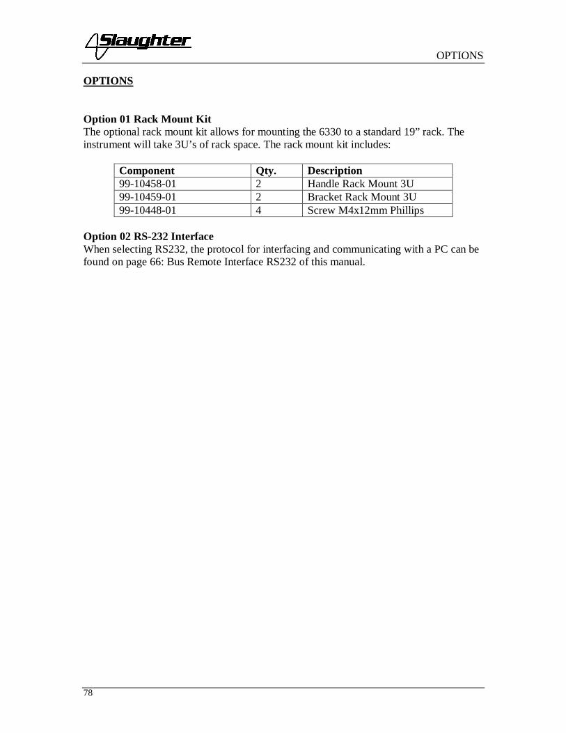
OPTIONS
78
OPTIONS
Option 01 Rack Mount KitThe optional rack mount kit allows for mounting the 6330 to a standard 19” rack. Theinstrument will take 3U’s of rack space. The rack mount kit includes:
Component Qty. Description99-10458-01 2 Handle Rack Mount 3U99-10459-01 2 Bracket Rack Mount 3U99-10448-01 4 Screw M4x12mm Phillips
Option 02 RS-232 InterfaceWhen selecting RS232, the protocol for interfacing and communicating with a PC can befound on page 66: Bus Remote Interface RS232 of this manual.

CALIBRATION
SECTION 2SERVICE MANUAL

CALIBRATION
80
CALIBRATION PROCEDURES
This instrument has been fully calibrated at the factory in accordance to our publishedspecifications. It has been calibrated with standards traceable to NIST. You will find inthis manual a copy of the "Certificate of Calibration". It is recommended that you havethis instrument recalibrated and a safety check done at least once per year. Slaughterrecommends you use "Calibration Standards" that are NIST traceable, or traceable toagencies recognized by NIST to keep this instrument within published specifications.
End user metrology standards or practices may vary. These metrology standardsdetermine the measurement uncertainty ratio of the calibration standards being used.Calibration adjustments can only be made in the Calibration mode and calibration checksor verification can only be made while operation in Test mode.
Calibration Equipment Required:The following standard equipment will be needed to properly calibrate your instrument.
A Standard AC Voltmeter with 4,000 Volts rangeA Standard AC Voltmeter with 6 Volts rangeA Standard DC Voltmeter with 4,000 Volts rangeA Standard DC Voltmeter with 1,000 Volts rangeA Standard AC Ammeter with 30 A rangeA Standard AC Milliammeter with 30 mA rangeA Standard DC Milliammeter with 5 mA rangeA Standard Resistor 100 kΩ/20Watt/1500VACA Standard Resistor 1 MΩ/0.25Watt/300VDCA Standard Resistor 50 MΩ/0.25Watt/1000VDCAdjustable AC power supply 0-277VAC, 8.4kVALow impedance adjustable load 7 – 30 , 8400 WAdjustable DC power supply 0-8VDC
Calibration InitializationTo enter the calibration mode the instrument must be in the OFF position. Using a pen orsmall screwdriver, press and hold the recessed calibration key on the rear panel, then turnon the input POWER switch. The display will show:
To calibrate AC voltage please follow procedure on next paragraph, to calibrate otherparameters use Up (∧) or Down (∨) arrow keys to scroll to the desired calibration point,then follow procedure on relative paragraph below.
When the calibration process is completed successfully and the instrument accepts theentered calibration data it will output one short “beep” and advance to the next calibration
01. AC 4000V

CALIBRATION
81
point, otherwise the instrument will output two short “beeps” and will not advance to thenext calibration point.
1. To calibrate AC VoltagePlease connect a standard 4000V AC Voltmeter to the HV and RETURN connectors.Then press the TEST button on the front panel. The instrument will provide around4000VAC on the output connectors and the display will show:
Press the Up (∧) or Down (∨) arrow keys to enter the reading of the standard ACVoltmeter into the instrument. Then press SET key to store the voltage setting and toadvance to the next calibration point or press the RESET button to return to thecalibration menu without changing the calibration setting. Press the EXIT key to exitfrom the calibration mode and to return to the test mode.
2. To calibrate DC VoltagePlease connect a standard 4000V DC Voltmeter to the HV and RETURN connectors.Press the Up (∧) or Down (∨) arrow keys until the display shows:
Then press the TEST button on the front panel. The instrument will provide around4000VDC on the output connectors and the display will show:
Press the Up (∧) or Down (∨) arrow keys to enter the reading of the standard DCVoltmeter into the instrument. Then press SET key to store the voltage setting and toadvance to the next calibration point or press the RESET button to return to thecalibration menu without changing the calibration setting. Press the EXIT key to exitfrom the calibration mode and to return to the test mode.
3. To calibrate IR VoltagePlease connect a standard 1000V DC Voltmeter to the HV and RETURN connectors.Press the Up (∧) or Down (∨) arrow keys until the display shows:
Then press the TEST button on the front panel. The instrument will provide around1000VDC on the output connectors and the display will show:
Voltage = XXXXV
02. DC 4000V
Voltage = XXXXV
03. IR 1000V
Voltage = XXXXV

CALIBRATION
82
Press the Up (∧) or Down (∨) arrow keys to enter the reading of the standard DCVoltmeter into the instrument. Then press SET key to store the voltage setting and toadvance to the next calibration point or press the RESET button to return to thecalibration menu without changing the calibration setting. Press the EXIT key to exitfrom the calibration mode and to return to the test mode.
4. To calibrate AC CurrentPlease connect a 100 kΩ resistor in series with the standard 30mA AC Milliammeter andconnect these across the HV and RETURN connectors of the instrument.Press the Up (∧) or Down (∨) arrow keys until the display shows:
Then press the TEST button on the front panel. The instrument will provide around1000VAC on the output connectors and the display will show:
Press the Up (∧) or Down (∨) arrow keys to enter the reading of the standard ACMilliammeter into the instrument. Then press SET key to store the current setting and toadvance to the next calibration point or press the RESET button to return to thecalibration menu without changing the calibration setting. Press the EXIT key to exitfrom the calibration mode and to return to the test mode.
5. To calibrate DC CurrentPlease connect a 100 kΩ resistor in series with the standard 5mA DC Milliammeter andconnect these across the HV and RETURN connectors of the instrument.Press the Up (∧) or Down (∨) arrow keys until the display shows:
Then press the TEST button on the front panel. The instrument will provide around500VDC on the output connectors and the display will show:
Press the Up (∧) or Down (∨) arrow keys to enter the reading of the standard DCMilliammeter into the instrument. Then press SET key to store the current setting and toadvance to the next calibration point or press the RESET button to return to the
04. AC 30.00mALoad = 100kΩ
Current XX.XXmA
05. DC 5.00mALoad = 100kΩ
Current X.XXmA

CALIBRATION
83
calibration menu without changing the calibration setting. Press the EXIT key to exitfrom the calibration mode and to return to the test mode.
6. To calibrate Insulation Resistance low rangePlease connect a 100kΩ standard resistor across the HV and RETURN connectors.Press the Up (∧) or Down (∨) arrow keys until the display shows:
Then press the TEST button on the front panel. The instrument will execute automaticcalibration process. The process does not require data entry. The instrument will providearound 300VDC on the output connectors and the display will show:
The instrument will output one short “beep” and advance to the next calibration pointwhen the automatic process is completed successfully, otherwise the instrument willoutput two short “beeps” and will not advance to the next calibration point.
7. To calibrate Insulation Resistance mid range 1When previous calibration point was completed successfully display will show:
Please connect a 1MΩ standard resistor across the HV and RETURN connectors.Then press the TEST button on the front panel. The instrument will execute automaticcalibration process. The process does not require data entry. The instrument will providearound 300VDC on the output connectors and the display will show:
The instrument will output one short “beep” and advance to the next calibration pointwhen the automatic process is completed successfully, otherwise the instrument willoutput two short “beeps” and will not advance to the next calibration point.
8. To calibrate Insulation Resistance mid range 2When previous calibration point was completed successfully display will show:
06. IR 0.99MΩLoad = 100kΩ
Automatic
07. IR 9.99MΩLoad = 1MΩ
Automatic
08. IR 99.99MΩ

CALIBRATION
84
Please connect a 50MΩ standard resistor across the HV and RETURN connectors.Then press the TEST button on the front panel. The instrument will execute automaticcalibration process. The process does not require data entry. The instrument will providearound 1000VDC on the output connectors and the display will show:
The instrument will output one short “beep” and advance to the next calibration pointwhen the automatic process is completed successfully, otherwise the instrument willoutput two short “beeps” and will not advance to the next calibration point.
9. To calibrate Insulation Resistance high rangeWhen previous calibration point was completed successfully display will show:
The 50MΩ standard resistor should be connected across the HV and RETURNconnectors of the instrument.Then press the TEST button on the front panel. The instrument will execute automaticcalibration process. The process does not require data entry. The instrument will providearound 150VDC on the output connectors and the display will show:
The instrument will output one short “beep” and advance to the next calibration pointwhen the automatic process is completed successfully, otherwise the instrument willoutput two short “beeps” and will not advance to the next calibration point.
10. To calibrate Ground Bond test voltagePlease connect a standard 6V AC Voltmeter across the CURRENT and RETURNconnectors of the instrument.Press the Up (∧) or Down (∨) arrow keys until the display shows:
Then press the TEST button on the front panel. The instrument will generate an output ofabout 6 VAC and the display will show:
Load = 50MΩ
Automatic
09. IR 999.9MΩLoad = 50MΩ
Automatic
10. GND 6.00V
Voltage = X.XXV

CALIBRATION
85
Press the Up (∧) or Down (∨) arrow keys to enter the reading of the standard ACVoltmeter into the instrument. Then press SET key to store the voltage setting and toadvance to the next calibration point or press the RESET button to return to thecalibration menu without changing the calibration setting. Press the EXIT key to exitfrom the calibration mode and to return to the test mode.
11. To calibrate Ground Bond test currentPlease connect the standard 30A AC Ammeter across the CURRENT and RETURNconnectors of the instrument.Press the Up (∧) or Down (∨) arrow keys until the display shows:
Then press the TEST button on the front panel. The display will show:
Press the Up (∧) or Down (∨) arrow keys to enter the reading of the standard ACAmmeter into the instrument. Then press SET key to store the current setting and toadvance to the next calibration point or press the RESET button to return to thecalibration menu without changing the calibration setting. Press the EXIT key to exitfrom the calibration mode and to return to the test mode.
12. To calibrate Functional Run test voltage
Step 1Please disconnect all meters from the instrument.Press the Up (∧) or Down (∨) arrow keys until the display shows:
Then press the TEST button on the front panel. Then press SET key to advance to thenext calibration point or press the RESET button to return to the calibration menu withoutchanging the calibration setting. Press the EXIT key to exit from the calibration modeand to return to the test mode.
Step 2Please connect the standard 0-277VAC power supply to the DUT I/P inputs of theinstrument. Connect the standard AC voltmeter to the DUT outputs.Press the Up (∧) or Down (∨) arrow keys until the display shows:
11. GND 30.0A
Current = XX.XA
12. RUN 277.0VStep 1: No Power Input
12. RUN Voltage

CALIBRATION
86
Then press the TEST button on the front panel. The display will show:
Press the Up (∧) or Down (∨) arrow keys to enter the reading of the standard ACvoltmeter into the instrument. Then press SET key to store the current setting and toadvance to the next calibration point or press the RESET button to return to thecalibration menu without changing the calibration setting. Press the EXIT key to exitfrom the calibration mode and to return to the test mode.
13. To calibrate the Functional Run test currentPlease connect a 30A resistor in series with the standard 30AAC ammeter and connectthese across the DUT Output Power Line and Neutral terminals.Press the Up (∧) or Down (∨) arrow keys until the display shows:
Then press the TEST button on the front panel and the display will show:
Press the Up (∧) or Down (∨) arrow keys to enter the reading of the standard ACammeter into the instrument. Then press SET key to store the current setting and toadvance to the next calibration point or press the RESET button to return to thecalibration menu without changing the calibration setting. Press the EXIT key to exitfrom the calibration mode and to return to the test mode
14. To calibrate the Functional Run test powerPlease connect a 10 resistor in series with the standard power meter’s current inputs.Connect the power meter’s voltage inputs to the DUT Output Line and Neutral terminalsof the instrument. Connect the AC power supply to the DUT I/P connectors of theinstrument and set the voltage for 225VAC.Press the Up (∧) or Down (∨) arrow keys until the display shows:
Step 2: ACV 250V Input
Automatic
13. RUN 30.0AL=30Amp,V=120-277VAC
Current = XX.XA

CALIBRATION
87
Then press the TEST button on the front panel and the display will show:
Press the Up (∧) or Down (∨) arrow keys to enter the reading of the power meter into theinstrument. Then press SET key to store the current setting and to advance to the nextcalibration point or press the RESET button to return to the calibration menu withoutchanging the calibration setting. Press the EXIT key to exit from the calibration modeand to return to the test mode
15. To calibrate the Functional Run test leakage currentPlease connect a standard Milliammeter to the DUT Power Outputs Line and Groundterminals. Connect the AC power supply to the DUT I/P of the instrument and set thevoltage to 18VAC.Press the Up (∧) or Down (∨) arrow keys until the display shows:
Then press the TEST button on the front panel and the display will show:
Press the Up (∧) or Down (∨) arrow keys to enter the reading of the standard ACMilliammeter into the instrument. Then press SET key to store the current setting and toadvance to the next calibration point or press the RESET button to return to thecalibration menu without changing the calibration setting. Press the EXIT key to exitfrom the calibration mode and to return to the test mode
16. To calibrate the Line Leakage test offsetPlease disconnect all meters from the instrument.Press the Up (∧) or Down (∨) arrow keys until the display shows:
14. RUN 8400WL=10 , V=220VAC
Power = XXXXW
15. RUN 10.0mADUT I/P=18VAC
Current = X.XXmA
16. LLT Offset
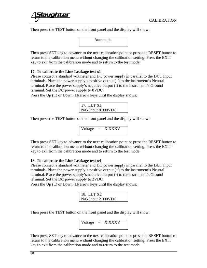
CALIBRATION
88
Then press the TEST button on the front panel and the display will show:
Then press SET key to advance to the next calibration point or press the RESET button toreturn to the calibration menu without changing the calibration setting. Press the EXITkey to exit from the calibration mode and to return to the test mode.
17. To calibrate the Line Leakage test x1Please connect a standard voltmeter and DC power supply in parallel to the DUT Inputterminals. Place the power supply’s positive output (+) to the instrument’s Neutralterminal. Place the power supply’s negative output (-) to the instrument’s Groundterminal. Set the DC power supply to 8VDC.Press the Up (∧) or Down (∨) arrow keys until the display shows:
Then press the TEST button on the front panel and the display will show:
Then press SET key to advance to the next calibration point or press the RESET button toreturn to the calibration menu without changing the calibration setting. Press the EXITkey to exit from the calibration mode and to return to the test mode.
18. To calibrate the Line Leakage test x4Please connect a standard voltmeter and DC power supply in parallel to the DUT Inputterminals. Place the power supply’s positive output (+) to the instrument’s Neutralterminal. Place the power supply’s negative output (-) to the instrument’s Groundterminal. Set the DC power supply to 2VDC.Press the Up (∧) or Down (∨) arrow keys until the display shows:
Then press the TEST button on the front panel and the display will show:
Then press SET key to advance to the next calibration point or press the RESET button toreturn to the calibration menu without changing the calibration setting. Press the EXITkey to exit from the calibration mode and to return to the test mode.
Automatic
17. LLT X1N/G Input 8.000VDC
Voltage = X.XXXV
18. LLT X2N/G Input 2.000VDC
Voltage = X.XXXV

CALIBRATION
89
19. To calibrate the Line Leakage test x16Please connect a standard voltmeter and DC power supply in parallel to the DUT Inputterminals. Place the power supply’s positive output (+) to the instrument’s Neutralterminal. Place the power supply’s negative output (-) to the instrument’s Groundterminal. Set the DC power supply to 0.5VDC.Press the Up (∧) or Down (∨) arrow keys until the display shows:
Then press the TEST button on the front panel and the display will show:
Then press SET key to advance to the next calibration point or press the RESET button toreturn to the calibration menu without changing the calibration setting. Press the EXITkey to exit from the calibration mode and to return to the test mode.
20. To calibrate the Line Leakage MDAPlease connect a standard current meter and DC power supply in series with the DUTPower Input terminals. Place the power supply’s positive output (+) to the instrument’sNeutral terminal. Place the power supply’s negative output (-) to the instrument’s Groundterminal. Set the power supply to 2.2VDC.Press the Up (∧) or Down (∨) arrow keys until the display shows:
Then press the TEST button on the front panel and the display will show:
Then press SET key to advance to the next calibration point or press the RESET button toreturn to the calibration menu without changing the calibration setting. Press the EXITkey to exit from the calibration mode and to return to the test mode.21. To calibrate the Line Leakage MDBPlease connect a standard current meter and DC power supply in series with the DUTPower Input terminals. Place the power supply’s positive output (+) to the instrument’sNeutral terminal. Place the power supply’s negative output (-) to the instrument’s Groundterminal. Set the power supply to 2.2VDC.Press the Up (∧) or Down (∨) arrow keys until the display shows:
19. LLT X16N/G Input 0.500VDC
Voltage = X.XXXV
20. LLT MDAN/G Input 2.200VDC
Current = XXXXuA
21. LLT MDBN/G Input 2.200VDC

CALIBRATION
90
Then press the TEST button on the front panel and the display will show:
Then press SET key to advance to the next calibration point or press the RESET button toreturn to the calibration menu without changing the calibration setting. Press the EXITkey to exit from the calibration mode and to return to the test mode.
22. To calibrate the Line Leakage MDCPlease connect a standard current meter and DC power supply in series with the DUTPower Input terminals. Place the power supply’s positive output (+) to the instrument’sNeutral terminal. Place the power supply’s negative output (-) to the instrument’s Groundterminal. Set the power supply to 2.2VDC.Press the Up (∧) or Down (∨) arrow keys until the display shows:
Then press the TEST button on the front panel and the display will show:
Then press SET key to advance to the next calibration point or press the RESET button toreturn to the calibration menu without changing the calibration setting. Press the EXITkey to exit from the calibration mode and to return to the test mode.
23. To calibrate the Line Leakage MDXPlease connect a standard current meter and DC power supply in series with the DUTPower Input terminals. Place the power supply’s positive output (+) to the instrument’sNeutral terminal. Place the power supply’s negative output (-) to the instrument’s Groundterminal. Set the power supply to 2.2VDC.Press the Up (∧) or Down (∨) arrow keys until the display shows:
Current = XXXXuA
22. LLT MDCN/G Input 2.200VDC
Current = XXXXuA
23. LLT MDXN/G Input 2.200VDC

CALIBRATION
91
Then press the TEST button on the front panel and the display will show:
Then press SET key to advance to the next calibration point or press the RESET button toreturn to the calibration menu without changing the calibration setting. Press the EXITkey to exit from the calibration mode and to return to the test mode.
24. Exit Calibration ModeWhen all calibration parameters are completed successfully the display will show:
Please press the EXIT key to exit from the calibration mode and to return to the testmode.
Current = XXXXuA
Calibration complete

PARTS LIST
92
Replacement Parts ListModel 6330
Rev: E 3/8/2011 ECO 5480-1
Part Number Qty. Ref. Designator DescriptionSupplied Accessories99-10460-01 1 OPTIONAL 3U Rack Mount Hardware99-10106-01 1 - Fuse 6.3A 250V Slow-Blow 20mm102-055-913 1 - High Voltage Cable125-013-001 1 - Cable Input Cord set USA99-10040-01 1 - Interlock Connector99-10467-01 1 - Adapter Box99-10457-01 1 LLT CASE LEAD Cable Assembly High Current Lead99-10468-01 1 LLT GROUND
LEADCable Assembly Ground Lead
99-10009-01 1 GND BNDOUTPUT
Cable Assembly High Current Output
99-10008-01 1 RETURN LEAD Cable Assembly High Current Return99-10469-01 1 LLT INPUT LINE LLT DUT Input cable LINE99-10470-01 1 LLT INPUT
NEUTRALLLT DUT Input cable NEUTRAL
99-10471-01 1 LLT OUTPUTLINE
LLT DUT HV Output Cable Line
99-10472-01 1 LLT OUTPUTNEUTRAL
LLT DUT HV Output Cable Neutral
99-10573-01 1 - RS232 CablePanel Components99-10018-01 2 - High Voltage Connector99-10312-01 1 - Power Switch 2P 15A/250V99-10016-01 1 - Earth Connector330-113-001 1 TEST Test Switch Green Lighted330-113-002 1 RESET Reset Switch Red Lighted99-10046-01 1 - HV Indicator LED175-946-013 1 - Feet Kit w/o Rubber Inserts175-974-002 4 - Rubber Insert for Feet99-10618-01 1 - 20 x 2 LCD Display99-10113-01 2 - Binding Post 30 Amp Red99-10112-01 2 - Binding Post 30 Amp Black (Return)PCB Assemblies99-10222-01 1 CKB-06 Keypad Board99-10321-01 1 AMP4320 Amplifier Board99-10322-01 1 HV4320 High Voltage Control Board99-10530-01 1 RY4320 HV AC/DC Switch Board99-10325-01 1 PWR7500 Input Voltage Select Board

PARTS LIST
93
99-10475-01 1 CON7500 Main Control Board99-10476-01 1 CON7128 LLT Control Board99-10477-01 1 MD7500 Measuring Device Board99-10478-01 1 SW7128 LLT Switching Board99-10583-01 1 RS232 RS232 Interface BoardPart Number Qty. Ref. Designator DescriptionInternal Components99-10529-01 1ea IC for CON4320
(IC2), CON7128(IC52)
IC SM89516AC
99-10304-01 1 CON7128 (IC52) IC SM8951A99-10324-01 1 IC 24 CON4320 IC 8951A99-10344-01 1 IC 40 IC ATF16V8B 20Pin PLCC99-10345-01 1 IC 39 CON4320 IC 29C020 EEPROM99-10496-01 1 T1 Input Transformer99-10497-01 1 T2 High Voltage Output Transformer

PARTS LIST
94
6330 Schematic Index
Drawing Number Description ReferenceDesignator
Pages
S06330 Wiring Diagram 6330 - 1
S99-10320 Main Control Board CON4320 7
S99-10322 HV Control Board HV4320 1
S99-10323 HV AC/DC Switch Board RY4320 1
S99-10321 Amplifier Board AMP4320 1
S99-10222 Keypad Board CKB-06 1
S99-10325 Input Voltage Select Board PWR3670 1
S99-10476 Run/LLT Control Board CON7128 9
S99-10478 Run/LLT Switching Board SW7128 2
S99-10477 External Measuring Device Board MD7500 1
S99-10583 RS-232 Interface Board RS232 1


