600 Roadside Design - Pages€¦ · Ditch sections that fall outside the shaded areas are...
72
600 Roadside Design Table of Contents 600.1 Introduction .......................................................................................................... 6-1 600.2 Clear Zone ........................................................................................................... 6-1 600.2.1 Parallel Embankment Slopes & Ditches ................................................ 6-2 600.2.2 Urban Lateral Offsets ............................................................................ 6-2 600.2.3 Operational Offsets on Urban Streets ................................................... 6-3 601 Warrants ............................................................................................................... 6-3 601.1 Roadside Barrier Warrants ................................................................................... 6-3 601.1.1 Obstacles .............................................................................................. 6-4 601.1.2 Slopes ................................................................................................... 6-4 601.1.3 Protection of Others .............................................................................. 6-4 601.1.4 Protection on Low Speed Roadways .................................................... 6-4 601.1.5 Protection on Very Low-Volume Local Roads (ADT < 400) .................. 6-5 601.1.6 Preservation of Safety Grading ............................................................. 6-5 601.2 Median Barrier Warrants ...................................................................................... 6-5 601.2.1 Safety Studies ....................................................................................... 6-5 601.3 NHS Criteria ......................................................................................................... 6-6 601.4 Design Considerations for Large Trucks .............................................................. 6-6 602 Site Considerations............................................................................................. 6-7 602.1 Roadside Protection ............................................................................................. 6-7 602.1.1 Location/Offset ...................................................................................... 6-7 602.1.2 Length of Need on Tangent Alignments ................................................ 6-7 602.1.3 Length of Need on Curved Alignments.................................................. 6-8 602.1.4 Grading for Barriers & End Treatments ................................................. 6-8 602.1.5 Guardrail with Curbs .............................................................................. 6-9 602.1.5.1 On High Speed Roadways ........................................................... 6-9 602.1.5.2 On Low Speed Roadways ............................................................ 6-9 602.1.5.3 End Treatments and Impact Attenuators in Curbed Sections .... 6-10 602.2 Median Protection .............................................................................................. 6-10 602.2.1 Shielding of Fixed Objects in the Median ............................................ 6-10 602.2.1.1 Narrow Median Barrier Installations ........................................... 6-10 602.2.1.2 Wide Median Barrier Installations ............................................... 6-10 602.2.1.3 Greatest Offset Method to Shield Center Median Piers ............. 6-10 602.2.2 Mitigation of Cross Median Crashes (CMC) ........................................ 6-10 602.2.2.1 Barrier Selection ......................................................................... 6-10 602.2.2.2 Cable Barrier Placement in the Median ...................................... 6-11 602.2.2.3 Cable Anchors ............................................................................ 6-11 602.2.2.4 Cable Barrier as the Primary Barrier System ............................. 6-11 602.3 Gore Area Protection ......................................................................................... 6-11 602.4 Protection at Drives and Side Roads ................................................................. 6-12 602.5 Protection at Bridges and Fixed Objects ............................................................ 6-12 602.5.1 Guardrail at Bridges & Large Culverts ................................................. 6-12 602.6 Protection at Drainage Structures ...................................................................... 6-12 602.6.1 Transverse Drainage ........................................................................... 6-13 602.6.2 Intersecting Embankments & Parallel Drainage .................................. 6-13 602.6.3 Special End Treatments ...................................................................... 6-14 602.7 Sight Distance Considerations ........................................................................... 6-14
Transcript of 600 Roadside Design - Pages€¦ · Ditch sections that fall outside the shaded areas are...

600 Roadside Design
Table of Contents 600.1 Introduction .......................................................................................................... 6-1 600.2 Clear Zone ........................................................................................................... 6-1
600.2.1 Parallel Embankment Slopes & Ditches ................................................ 6-2 600.2.2 Urban Lateral Offsets ............................................................................ 6-2 600.2.3 Operational Offsets on Urban Streets ................................................... 6-3
601 Warrants ............................................................................................................... 6-3
601.1 Roadside Barrier Warrants ................................................................................... 6-3 601.1.1 Obstacles .............................................................................................. 6-4 601.1.2 Slopes ................................................................................................... 6-4 601.1.3 Protection of Others .............................................................................. 6-4 601.1.4 Protection on Low Speed Roadways .................................................... 6-4 601.1.5 Protection on Very Low-Volume Local Roads (ADT < 400) .................. 6-5 601.1.6 Preservation of Safety Grading ............................................................. 6-5
601.2 Median Barrier Warrants ...................................................................................... 6-5 601.2.1 Safety Studies ....................................................................................... 6-5
601.3 NHS Criteria ......................................................................................................... 6-6 601.4 Design Considerations for Large Trucks .............................................................. 6-6
602 Site Considerations ............................................................................................. 6-7
602.1 Roadside Protection ............................................................................................. 6-7 602.1.1 Location/Offset ...................................................................................... 6-7 602.1.2 Length of Need on Tangent Alignments ................................................ 6-7 602.1.3 Length of Need on Curved Alignments.................................................. 6-8 602.1.4 Grading for Barriers & End Treatments ................................................. 6-8 602.1.5 Guardrail with Curbs .............................................................................. 6-9 602.1.5.1 On High Speed Roadways ........................................................... 6-9 602.1.5.2 On Low Speed Roadways ............................................................ 6-9 602.1.5.3 End Treatments and Impact Attenuators in Curbed Sections .... 6-10
602.2 Median Protection .............................................................................................. 6-10 602.2.1 Shielding of Fixed Objects in the Median ............................................ 6-10 602.2.1.1 Narrow Median Barrier Installations ........................................... 6-10 602.2.1.2 Wide Median Barrier Installations ............................................... 6-10 602.2.1.3 Greatest Offset Method to Shield Center Median Piers ............. 6-10 602.2.2 Mitigation of Cross Median Crashes (CMC) ........................................ 6-10 602.2.2.1 Barrier Selection ......................................................................... 6-10 602.2.2.2 Cable Barrier Placement in the Median ...................................... 6-11 602.2.2.3 Cable Anchors ............................................................................ 6-11 602.2.2.4 Cable Barrier as the Primary Barrier System ............................. 6-11
602.3 Gore Area Protection ......................................................................................... 6-11 602.4 Protection at Drives and Side Roads ................................................................. 6-12 602.5 Protection at Bridges and Fixed Objects ............................................................ 6-12
602.5.1 Guardrail at Bridges & Large Culverts ................................................. 6-12 602.6 Protection at Drainage Structures ...................................................................... 6-12
602.6.1 Transverse Drainage ........................................................................... 6-13 602.6.2 Intersecting Embankments & Parallel Drainage .................................. 6-13 602.6.3 Special End Treatments ...................................................................... 6-14
602.7 Sight Distance Considerations ........................................................................... 6-14
600 Roadside Design
603 Roadside Safety Devices .................................................................................. 6-14 603.1 Longitudinal Barriers .......................................................................................... 6-14
603.1.1 Flexible Cable Systems ....................................................................... 6-15 603.1.1.1 Generic Low Tension Cable ....................................................... 6-15 603.1.1.2 Proprietary High Tension Cable Systems ................................... 6-15
603.1.2 Semi Rigid Barriers.............................................................................. 6-15 603.1.2.1 Type MGS Guardrail ................................................................... 6-16 603.1.2.3 Barrier Design Guardrail ............................................................. 6-16 603.1.2.5 Long Span Guardrail .................................................................. 6-16
603.1.4 Rigid Concrete Barrier ......................................................................... 6-16 603.1.4.1 Single Slope Barrier .................................................................... 6-17 603.1.4.2 Types B & B1 .............................................................................. 6-17 603.1.4.3 Type C & C1 ............................................................................... 6-17 603.1.4.4 Type D ........................................................................................ 6-17 603.1.4.5 New Jersey Shape ..................................................................... 6-18 603.1.4.6 Portable Concrete Barrier ........................................................... 6-18 603.1.4.7 Zone of Influence ........................................................................ 6-18
603.2 Characteristics of Anchor Assemblies & Impact Attenuators ............................. 6-18 603.2.1 Energy Absorbing ................................................................................ 6-18 603.2.2 Gating .................................................................................................. 6-19 603.2.3 Redirection .......................................................................................... 6-19 603.2.4 Proprietary Products ............................................................................ 6-19
603.3 Anchor Assemblies ............................................................................................ 6-20 603.3.1 Buried-In-Backslope ............................................................................ 6-20 603.3.2 Type B ................................................................................................ 6-20 603.3.3 Type E ................................................................................................ 6-20 603.3.4 Type A .............................................................................................. ..6-21 603.3.5 Type T ................................................................................................. 6-21
603.4 Impact Attenuators ............................................................................................. 6-21 603.4.1 Type 1 ................................................................................................. 6-22 603.4.2 Type 2 ................................................................................................. 6-22 603.4.3 Type 3 ................................................................................................. 6-22 603.4.4 Work Zone Impact Attenuators ............................................................ 6-23 603.4.5 Sand Barrels ........................................................................................ 6-23
603.5 Bridge Terminal Assemblies .............................................................................. 6-23 603.5.1 Type 1 ................................................................................................. 6-23 603.5.2 Type 1 Barrier Design ......................................................................... 6-24 603.5.3 Type 2 ................................................................................................. 6-24 603.5.4 Previous Types 3 & 4 .......................................................................... 6-24
603.6 Concrete Barrier End Treatment ........................................................................ 6-24
604 Glare Screen ...................................................................................................... 6-24 604.1 Median Glare Screen ............................................................................. 6-25 604.3 Glare Screen Options ............................................................................. 6-25
605 Rumble Strips .................................................................................................... 6-25 605.1 Shoulder Rumble Strips ..................................................................................... 6-25
605.1.1 Locations ............................................................................................. 6-25 605.1.2 Section Not Used ................................................................................ 6-26 605.1.3 Lateral Clearances for Machinery ........................................................ 6-26 605.1.4 Divided Highways ................................................................................ 6-26 605.1.5 Existing Shoulders ............................................................................... 6-26 605.1.6 Bicycle Considerations ........................................................................ 6-26 605.1.7 Residential Areas ................................................................................ 6-27

600 Roadside Design
605.1.8 Maintenance of Traffic ......................................................................... 6-27 605.2 Rumble Strips Across Traveled Lanes ............................................................... 6-27
605.2.1 Locations ............................................................................................. 6-27
606 Fence .................................................................................................................. 6-28 606.1 Purpose .............................................................................................................. 6-28 606.2 Types ................................................................................................................. 6-28 606.3 Fence on Freeways ............................................................................................ 6-28
606.3.1 Urban Freeways .................................................................................. 6-28 606.3.2 Rural Freeways ................................................................................... 6-28 606.3.3 Freeway Fence Design Conditions...................................................... 6-28 606.3.4 Exceptions to Continuous Freeway Fencing ....................................... 6-29
606.4 Fence on Arterials .............................................................................................. 6-29 606.4.1 Urban Arterials .................................................................................... 6-29 606.4.2 Rural Arterials ...................................................................................... 6-29 606.4.3 Arterial Fence Design .......................................................................... 6-29
606.5 Fence on Collectors ........................................................................................... 6-30 606.6 Lateral Location of Fence ................................................................................... 6-30 606.7 Fence Approval .................................................................................................. 6-30 606.8 Bridge Vandal Protection Fence ........................................................................ 6-30
List of Figures .......................................................................................................... 6-31

600 Roadside Design
This page is intentionally blank
600 Roadside Design
July 2017 6-1
600.1 Introduction This chapter discusses concepts related to roadside safety features which are intended to reduce occurrences of run-off-the-road crashes and reduce the severity of impact when such an incident does occur. The AASHTO Roadside Design Guide contains additional information on roadside design. Safety devices are themselves fixed objects, and while they may decrease crash severity, they may also increase the total number of impacts. The potential for impacts can be reduced by placing the safety device as close to the hazard being shielded and as far from the traveled lanes as permitted by the following standards. Roadside safety devices are hazards and must result in a less severe crash than the hazard being shielded.
600.2 Clear Zone Clear Zone The unobstructed, traversable area provided beyond the edge of the through traveled way for the recovery of errant vehicles. The clear zone includes shoulders, bike lanes, or auxiliary lanes, except those auxiliary lanes that function like through lanes. Ideally, there should be no obstructions within the clear zone; however, if an obstruction cannot be removed, then engineering judgment must be used to determine how to treat it. When a warranting feature cannot be removed, the clear zone distances given in Figure 600-1, may be used as minimum values. These widths are based on design speed, traffic volume, and the combination of foreslopes and backslopes on the typical cross section for the roadway. These minimum values should not erroneously be interpreted as permitting or encouraging the construction of potential hazards immediately outside the clear zone at what may be deemed a “safe” distance from the edge of the through traveled lanes. Rather, the clear zone width should be increased if a site investigation indicates that doing so would significantly lessen the potential for accidents. For example, if an obstruction exists just outside the required clear zone in an otherwise obstruction-free area, it should be considered for removal or protection. For curves with a history of run-off-the-road crashes and a Degree of Curve of 2°00' or greater, Figure 600-1 also provides a table of adjustment factors based on design speed that should be used to extend the clear zone. In these cases, the designer should ensure that the roadway has proper superelevation before evaluating the curve’s effect on the clear zone. The preferred order of corrective treatment for fixed objects and non-traversable hazards located within the clear zone is as follows: 1. Remove the obstacle. 2. Redesign the obstacle so that it can be safely traversed. 3. Relocate the obstacle to a point where it is less likely to be struck. 4. Reduce the impact severity by using an appropriate breakaway device. 5. Shield the obstacle with a longitudinal traffic barrier designed for redirection or use a crash cushion. 6. Delineate the obstacle if the above alternatives are not appropriate.
600 Roadside Design
July 2017 6-2
The overall intent of roadside design is to strive for a forgiving highway. Designing a project exclusively to meet minimum clear zone values may result in a roadside that is not as safe as it could be. On the other hand, the cost of clearing some roadsides may greatly exceed the associated benefits to the traveling public. The optimum solution lies in the judicious application of engineering judgment coupled with a sincere desire to produce safe roadways. 600.2.1 Parallel Embankment Slopes & Ditches Embankment slopes parallel to the roadway fall into the following categories: 1. Recoverable Slopes – Slopes on which encroaching motorists can generally stop their vehicles or
slow down enough to return safely to the roadway. Slopes 4:1 or flatter are considered recoverable. 2. Non-recoverable Slopes - Slopes which may be safely negotiated but are generally too steep for most
motorists to stop their vehicles or to return easily to the roadway. Slopes steeper than 4:1 up to and including 3:1 are considered traversable but non-recoverable if they are smooth and free of fixed-object hazards. Since a high percentage of encroaching vehicles will reach the toe of these slopes, a clear runout area at the toe is desirable.
3. Critical Slopes - Slopes steeper than 3:1 on which vehicles are likely to overturn. Backslopes tend to slow an errant vehicle and are therefore not as critical as foreslopes. They may, under certain conditions, be as steep as 1:1. Roadside ditches are generally categorized as traversable or non-traversable. Figures 307-10 and 307-11 present preferred designs for ditches with gradual and abrupt slope changes, respectively. Ditches that fall within the shaded areas of these figures are considered traversable and are preferred for use within the clear zone. Ditch sections that fall outside the shaded areas are considered non-traversable and should generally be located outside the clear zone. There are certain conditions, however, under which these sections may be considered for use within the clear zone. 3R projects; projects with limited right-of-way or rugged terrain; and low volume or low speed roads (particularly if the channel bottom and backslopes are free of any fixed objects) may utilize non-traversable ditch sections when traversable ditches are impractical. In determining a clear zone width, only recoverable foreslopes (4:1 or flatter), traversable ditches, and backslopes 3:1 or flatter may be included. The recovery area includes the clear zone width plus any non-recoverable slope (over 4:1 through 3:1). These relationships are shown in Figure 600-2. Several examples of clear zone calculations are included after the figures. 600.2.2 Urban Lateral Offsets Research has found that curb has very little effect on errant vehicles and thus the clear zone should be calculated as if the curb was not present (based on speed and traffic, Figure 600-1). Clear Zone is intended to provide a recovery area for errant vehicles. While designers should always strive to keep hazards as far away from the through traveled way as possible, it may not always be practical to provide the Clear Zone on transportation facilities in urban areas where right-of-way is often constrained. On urban facilities where Clear Zone cannot be provided, a minimum lateral offset to fixed objects of 8 feet from the edge of through traveled way for uncurbed roadways is acceptable. On very low speed curbed facilities (35 mph and less), the Operational Offset as described in 600.2.3 is acceptable for design features that are functionally necessary (non-breakaway signs and luminaire supports, utility poles, fire hydrants, bus stops, etc.). Otherwise, low speed curbed facilities, shall utilize a minimum Urban Lateral Offset of 4 feet from face of curb. For higher risk locations such as along the outside of
600 Roadside Design
July 2017 6-3
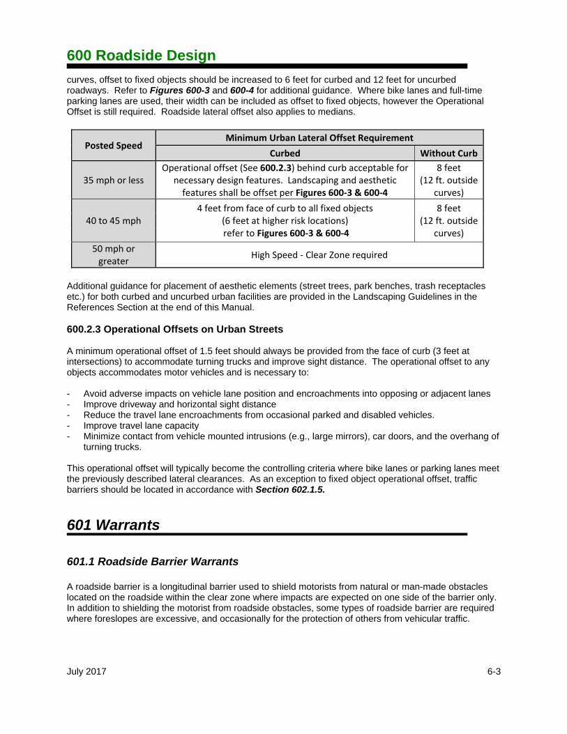
curves, offset to fixed objects should be increased to 6 feet for curbed and 12 feet for uncurbed roadways. Refer to Figures 600-3 and 600-4 for additional guidance. Where bike lanes and full-time parking lanes are used, their width can be included as offset to fixed objects, however the Operational Offset is still required. Roadside lateral offset also applies to medians.
Posted Speed Minimum Urban Lateral Offset Requirement
Curbed Without Curb
35 mph or less Operational offset (See 600.2.3) behind curb acceptable for
necessary design features. Landscaping and aesthetic features shall be offset per Figures 600‐3 & 600‐4
8 feet (12 ft. outside
curves)
40 to 45 mph 4 feet from face of curb to all fixed objects
(6 feet at higher risk locations) refer to Figures 600‐3 & 600‐4
8 feet (12 ft. outside
curves)
50 mph or greater
High Speed ‐ Clear Zone required
Additional guidance for placement of aesthetic elements (street trees, park benches, trash receptacles etc.) for both curbed and uncurbed urban facilities are provided in the Landscaping Guidelines in the References Section at the end of this Manual. 600.2.3 Operational Offsets on Urban Streets A minimum operational offset of 1.5 feet should always be provided from the face of curb (3 feet at intersections) to accommodate turning trucks and improve sight distance. The operational offset to any objects accommodates motor vehicles and is necessary to: - Avoid adverse impacts on vehicle lane position and encroachments into opposing or adjacent lanes - Improve driveway and horizontal sight distance - Reduce the travel lane encroachments from occasional parked and disabled vehicles. - Improve travel lane capacity - Minimize contact from vehicle mounted intrusions (e.g., large mirrors), car doors, and the overhang of
turning trucks. This operational offset will typically become the controlling criteria where bike lanes or parking lanes meet the previously described lateral clearances. As an exception to fixed object operational offset, traffic barriers should be located in accordance with Section 602.1.5.
601 Warrants
601.1 Roadside Barrier Warrants A roadside barrier is a longitudinal barrier used to shield motorists from natural or man-made obstacles located on the roadside within the clear zone where impacts are expected on one side of the barrier only. In addition to shielding the motorist from roadside obstacles, some types of roadside barrier are required where foreslopes are excessive, and occasionally for the protection of others from vehicular traffic.

600 Roadside Design
July 2017 6-4
601.1.1 Obstacles Roadside obstacles may be fixed objects or non-traversable terrain. Roadside obstacles located within the clear zone area may or may not require barrier protection. Barriers should be considered in the following circumstances: 1. At bridges, piers and abutments. 2. At culverts, pipes and headwalls depending on traffic volumes, and the culvert’s size, location and
end treatment. (See Section 602.6 for additional details.) 3. At non-breakaway sign and light supports. 4. At rough slopes in cut sections. 5. At utility poles that cannot justifiably be relocated. 6. At bodies of water or BMP detention ponds where the normal depth exceeds one foot depending on
the location and likelihood of encroachment. 7. At transverse ditches if the likelihood of a head-on impact is high. 8. At retaining walls if the anticipated maximum angle of impact is 15 degrees or where there may be
snagging potential. (Estimating an encroaching vehicle’s angle of impact is usually done using engineering judgment. In general, higher angles of impact are expected on the outside of curves and at locations where items are flared relative to the roadway.)
Barriers are required to protect mechanically stabilized earth (MSE) retaining wall within the clear zone.
9. At unprotected Noise Walls. Accident experience, either at the site or at a comparable site, will often be the deciding factor with respect to the placement or omission of a barrier. In all cases, the preferred alternative is to keep the entire clear zone free of fixed objects wherever economically feasible. 601.1.2 Slopes Embankment height and steepness of foreslopes are the basic factors to be considered in determining the need for barrier slope protection. Figure 601-1 should be used to determine roadside barrier warrants for embankments. 601.1.3 Protection of Others Barriers are sometimes required to protect others (schools, residences, businesses, pedestrians, bicyclists, etc.) from vehicular traffic. Barrier criteria for protection of others from errant vehicles are not as defined as in other barrier warrant cases. Such decisions are normally made using accident experience, either at the site or at comparable locations along with engineering judgment. 601.1.4 Protection on Low Speed Roadways Barrier protection on city streets and urban type facilities with design speeds less than 50 mph is not normally required. However, on roadways where the design speed is greater than 25 and less than 50

600 Roadside Design
July 2017 6-5
mph, the designer should specify protection at locations where geometric conditions, accident experience or other circumstances indicate that protection should be considered. 601.1.5 Protection on Very Low-Volume Local Roads (ADT 400) The guidelines presented elsewhere in this section were developed using the AASHTO Roadside Design Guide. Guidelines contained in the AASHTO Guidelines for the Geometric Design of Very Low-Volume Local Roads (less than or equal to 400 ADT) may be used in lieu of those presented here. On roads with very low traffic volumes, research has found that roadside clear zones provide very little benefit, and that traffic barriers are not generally cost-effective. With no criteria to identify appropriate locations where a clear zone or barrier may be warranted, the very low-volume guidelines provide great flexibility to the designer in exercising engineering judgment to decide when it is appropriate to provide improved roadsides. These guidelines apply to both new construction and existing roads. A clear zone of any width should provide some contribution to safety, so when feasible to do so at little or no additional cost, it should be considered for very low-volume local roads. 601.1.6 Preservation of Safety Grading Designers should preserve unobstructed areas on roadway designed and constructed with safety grading (Section 307.2.1). Typically, safety grading was part of the original construction and is intended to provide a safe recovery area outside of the required clear zone. These unobstructed areas should not be used to locate hazards, such as camera towers, ITS or WIM equipment, BMP detention ponds or aesthetic landscaping. To ensure driver safety and the financial investment made in safety grading the addition of hazards should be located behind existing barriers or as far away from traveled lanes as possible.
601.2 Median Barrier Warrants A median barrier is a longitudinal barrier used to separate opposing traffic on divided highways having relatively flat, traversable medians. Figure 601-2 provides barrier warrants for freeways to determine the need for median barriers, based on the width of the median and the volume of traffic on the facility. It may also be used for expressways with full access control. The use of the terms freeway and expressway in this instance apply to the operational characteristics of the highway, not necessarily the functional class designation. The use of median barrier on divided highways that do not have full access control requires engineering judgment and analysis with consideration to such items as right of way constraints, property access needs, sight distance at intersections, barrier end termination, etc. A median barrier may be high tensioned cable, guardrail, or concrete barrier. If the median is wide enough so that the barrier is outside the clear zone of opposing traffic, then roadside barrier warrants may be used. 601.2.1 Safety Studies It is recommended that a safety study be conducted to determine if median barrier protection would be beneficial at locations shown as optional in Figure 601-2. If barrier is chosen, see Section 602.2.2 for median barrier design considerations.
600 Roadside Design
July 2017 6-6
601.3 NHS Criteria Highway safety features, including longitudinal barriers, anchor assemblies, bridge terminal assemblies and impact attenuators installed on the National Highway System (NHS) must demonstrate satisfactory crash worthy performance and be accepted by the FHWA. The AASHTO Manual for Assessing Safety Hardware, (MASH) contains the current recommendations for testing and evaluating the crashworthy performance of barriers and has replaced NCHRP Report 350: Recommended Procedures for the Safety Performance Evaluation of Highway Features for the evaluation of new devices. Crashworthiness is currently accepted if either of the following conditions are met:
1. A barrier system has met all of the evaluation criteria listed in MASH or NCHRP Report 350 for each of the required crash tests, or
2. A barrier system has been evaluated and found acceptable as a result of an in-service performance evaluation.
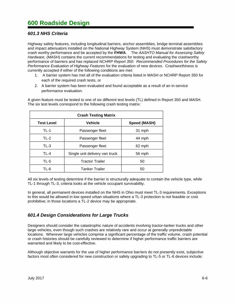
A given feature must be tested to one of six different test levels (TL) defined in Report 350 and MASH. The six test levels correspond to the following crash testing matrix:
Crash Testing Matrix
Test Level Vehicle Speed (MASH)
TL-1 Passenger fleet 31 mph
TL-2 Passenger fleet 44 mph
TL-3 Passenger fleet 62 mph
TL-4 Single unit delivery van truck 56 mph
TL-5 Tractor Trailer 50
TL-6 Tanker Trailer 50
All six levels of testing determine if the barrier is structurally adequate to contain the vehicle type, while TL-1 through TL-3, criteria looks at the vehicle occupant survivability. In general, all permanent devices installed on the NHS in Ohio must meet TL-3 requirements. Exceptions to this would be allowed in low speed urban situations where a TL-3 protection is not feasible or cost prohibitive; in those locations a TL-2 device may be appropriate.
601.4 Design Considerations for Large Trucks Designers should consider the catastrophic nature of accidents involving tractor-tanker trucks and other large vehicles, even though such crashes are relatively rare and occur at generally unpredictable locations. Wherever large vehicles comprise a significant percentage of the traffic volume, crash potential or crash histories should be carefully reviewed to determine if higher performance traffic barriers are warranted and likely to be cost-effective. Although objective warrants for the use of higher performance barriers do not presently exist, subjective factors most often considered for new construction or safety upgrading to TL-5 or TL-6 devices include:

600 Roadside Design
July 2017 6-7
1. High percentage of heavy vehicles (along major corridors, on hazardous material routes, or near hazardous industries),
2. Adverse geometrics (vehicle conflict points, sharp curvature, long downhill grades, poor sight
distance, or adverse pavement surfaces like shoulder wedges or reverse superelevation on shoulders), and
3. Severe consequences associated with the penetration of a large vehicle (buildings or transit facilities
underneath a bridge or multi-level interchange, sensitive environmental areas, or at critical bridges and tunnels).
602 Site Considerations Standards and guidelines are presented in this section for certain general site conditions; however, a site visit is essential to ensure that all design considerations have been addressed.
602.1 Roadside Protection When a roadside obstacle needs to be shielded, the designer should initially consider the most flexible barrier system installed as far from the traveled way as possible. Subsequent systems should be considered in order of increasing strength and decreasing distance from the roadway. In general, the designer should consider options for roadside protection in the following order:
1. Install flared guardrail and either terminate the end outside the clear zone or bury it into a backslope.
2. Install tangential guardrail and terminate the end with a Type B flared end terminal.
3. Install tangential guardrail and terminate the end with a Type E tangential end terminal.
4. Install concrete barrier according to Section 603.1.2 and terminate the end according to Section
603.6.
602.1.1 Location/Offset The normal roadside barrier location, with respect to the edge of traveled lanes, is shown in Figure 301-3. Minimum barrier clearances, measured from the face of the barrier to the face of the obstacle, are shown in Figure 603-2. (See Section 603.4 for minimum clearances for impact attenuators.) Although variations from these offsets may occur as a result of reduced graded shoulder width, the face of guardrail should not be located closer than 4 feet to the edge of the traveled lane. See Section 602.1.5 for guidelines concerning the use of curb with guardrail. 602.1.2 Length of Need on Tangent Alignments Length of need is the total length of a longitudinal barrier that is needed to shield an area of concern (warranting feature). The length of need point in a gating end terminal or impact attenuator determines how much of the end treatment can be contributed to the length of need for the barrier. If it is determined that barrier protection is required to shield a fixed object, Figure 602-1 should be used to determine the length of need. The primary variables are the Runout Length (LR) and the Lateral Extent of the Hazard (LH). The Runout Length is the theoretical distance needed for an errant vehicle leaving the

600 Roadside Design
July 2017 6-8
roadway to come to a stop. The Lateral Extent of the Hazard is the distance from the edge of the through traveled way to the far side of the hazard or to the edge of the clear zone if the hazard extends beyond the clear zone. The other three variables are the Tangent Length of barrier (LI,) the Lateral Distance from edge of the through traveled way (L2), and the Flare Rate (a:b). The formula in Figure 602-1 shown for computing the barrier length of need is appropriate where tangent roadways are involved. Short runs of barrier should be avoided where economically feasible. Gaps of 300 feet or less between adjacent runs of guardrail should be closed. Sample Calculations for length of need on tangent alignments are included in the Examples. 602.1.3 Length of Need on Curved Alignments Horizontal curvature of a roadway may have an effect in determining the barrier length of need in roadway design. In general, the length of need for a barrier on the outside of curves with a degree of curvature equal to 2°00' or flatter can be calculated as if the barrier was installed tangentially. However, a vehicle leaving the roadway on the outside of a curve sharper than this will generally follow a tangential runout path. For those cases involving a horizontal curve sharper than the limiting values given above, rather than using the theoretical LR distance, the tangent line from the curve to the outside edge of the warranting feature (or to the clear zone) should be used to determine the appropriate length of barrier needed (See Figure 602-2.) The guardrail should not be flared in these locations, since the potential impact angles would generally exceed acceptable design limits. Lengths of need should not be adjusted on the inside of horizontal curves. These locations should be treated as if they were on a tangent and LR should be measured along the length of the curve. Sample Calculations for length of need on curved alignments are included in the Examples. 602.1.4 Grading for Barriers & End Treatments To function properly, anchor assemblies and impact attenuators need to be installed with proper grading. The grading is designed to ensure that an impacting vehicle strikes the device at the appropriate height and with all four wheels on the ground. It also helps to reduce the potential for snagging and vehicle rollover during and after impact. Adequate earthwork and excavation should be included in the plans to ensure that all devices have proper grading. Ideally, the area immediately behind and downstream of all gating terminals should be reasonably traversable and free from fixed objects to the extent practical. A 20 feet by 75 foot area with 10:1 maximum slopes is required. When this is not practical, due to possible impacts to streams, and wetlands, the designer should consider alternatives. Also, there may be situations where existing conditions may preclude the acquisition of additional rights-of-way or easements necessary to build fill slopes that accommodate this grading. In these situations, it may be advisable to select a terminal that requires less extensive grading (i.e. non-gating or re-directive, see Section 603.2.1) or extend a run of guardrail so that the terminal may be placed on more favorable terrain, or buried in the backslope. The designer should attempt to provide a clear area with recoverable slopes (4:1 or flatter) over the same 20 feet by 75 feet area. If a clear runout path is not attainable, this area should be similar in character to the upstream, unshielded roadside area. In most cases, longitudinal barriers should not be located on slopes steeper than 10:1. Therefore, where a barrier is located outside the graded shoulder, special grading generally will be required to provide

600 Roadside Design
July 2017 6-9
slopes that are 10:1 or flatter. Also, 6:1 slopes are of particular concern due to vehicle ramping effects. Barriers installed on 6:1 slopes should be limited to cases where the barrier is located at least 12 feet or more from the edge of the break point for the 6:1 slope to minimize the potential for an errant vehicle to vault over the guardrail. The Buried-in-Backslope Anchor Assembly is one exception that has been designed specifically for 4:1 or flatter slopes. MGS Guardrail may be used with 8:1 approach slopes (See Section 603.3.1 for additional information.) 602.1.5 Guardrail with Curbs Curbs are generally classified as mountable or barrier curbs. Vehicles can, and do, safely traverse mountable curbs. Barrier curbs tend to inhibit vehicles from crossing over them at low speeds, but they are not a substitute for longitudinal barriers. When guardrail must be used in conjunction with a curb, the location of the guardrail relative to the curb should be carefully considered to minimize unacceptable post impact vehicle trajectories. When a vehicle strikes a curb, the resulting trajectory may cause the vehicle to impact the guardrail too high. In some cases the vehicle could clear the guardrail altogether. If guardrail is warranted and curbs are present, then the face of Type MGS guardrail should be located within 6 inches behind the face of the curb. Because of the vehicle vaulting potential, if the guardrail cannot be placed as described above, then the guardrail should be installed well behind the curb to allow the vehicle suspension to return to a normal state as shown in the following table.
Design Speed Guardrail at Curb Guardrail Behind Curb
Up to 45 mph Maximum of 6 inch sloping faced curb:MGS guardrail up to 6 in. behind curb
No closer than 8 feet.
45 and 50 mph Maximum of 6 inch sloping faced curb:MGS guardrail up to 6 in. behind curb
No closer than 13 feet.
Over 50 mph Maximum of 4 inch sloping faced curb:MGS guardrail up to 6 in. behind curb Above 55 mph, the sloping face of the curb should be 3:1 or flatter and 4 inches or smaller.
Guardrail should not be located behind curb.
602.1.5.1 On High Speed Roadways All guardrail on curbed roadways with a design speed of 50 mph or greater preferably should be located so the face of guardrail is at the face of curb. When curb and gutter is used, the gutter pan width will need to be increased to comply with these guidelines and to maintain a minimum 4 feet guardrail offset from the traveled way. The curb height should be limited to 4 inches or less when used in conjunction with guardrail on high speed roadways. 602.1.5.2 On Low Speed Roadways Guardrail is not normally used on curbed roadways having design speeds less than 50 mph (see Section 601.1.4). Where guardrail is deemed necessary on these roadways, the same criteria used for roadways with design speeds of 50 mph or greater is recommended. However, since the risk of vaulting is considerably less on low speed roadways, the designer may give more consideration to the location of the guardrail relative to the edge of traveled way than to its location relative to the curb.

600 Roadside Design
July 2017 6-10
602.1.5.3 End Treatments and Impact Attenuators in Curbed Sections None of the approved anchor assemblies or impact attenuators listed in Sections 603.3 and 603.4 have been designed or tested for use with curbs; consequently, the designer should use the guidelines provided for uncurbed sections in addition to engineering judgment and recommendations from the manufacturer to select end treatments in curbed sections. The current recommendation from product vendors is to ensure curbs are not present (if practical) along the length of the product and for a distance of 50 feet in advance of the product. When terminating or removing curbs in the vicinity of end treatments and impact attenuators remember to taper the curb height from 4 or 6 inches to flush with the pavement over a distance of 10 feet.
602.2 Median Protection Two types of shielding are necessary in medians. First, shielding of fixed objects is required if located in the clear zone of either direction of traffic. Second, if the median width warrants or a safety study shows a history or potential for Cross Median Crashes some type of barrier system may be needed. See Section 602.2.2. 602.2.1 Shielding of Fixed Objects in the Median When a median hazard requires protection, the treatment depends upon the available width of the median. For the purposes of installing barrier, a median is considered wide when the barrier installed in the median does not extend into the clear zone of the opposing side of traffic. Conversely, when the guardrail run extends into the clear zone of the opposite side of traffic, the median is considered narrow. 602.2.1.1 Narrow Median Barrier Installations Refer to SCD MGS-6.1 and MGS-6.2 Design A for details. 602.2.1.2 Wide Median Barrier Installations Refer to SCD MGS-6.1 and MGS-6.2 Design B for details. 602.2.1.3 Greatest Offset Method to Shield Center Median Piers Another design for pier protection (refer to SCD MGS-6.2) used by some Districts, is to shield center median piers with concrete barrier. This design uses concrete barrier to encase the pier (SCD RM-4.4), and then taper the concrete barrier to the end section (SCD RM-4.6). Finally install two narrow Type 2 Impact Attenuators, one at each end. This eliminates the need for perhaps hundreds of feet of guardrail as shown in SCD MGS-6.2. Contact the Office of Roadway Engineering for more information and design details. Proper grading in advance and alongside of the barrier is crucial in ensuring proper performance. 602.2.2 Mitigation of Cross Median Crashes (CMC) 602.2.2.1 Barrier Selection If a median barrier is determined to be necessary for shielding of CMC (Section 601.2), then the selection of the type of barrier to be used in the median is based on several factors, including the Test Level desired, median cross section, and barrier deflection.
600 Roadside Design
July 2017 6-11
Test Level - A safety study should determine the causes of CMC to determine the type of vehicle involved, and barrier selection should be based on the study. Guardrail is rated for TL-3 protection, High Tension Cable products are either rated to TL-3 or TL-4 (single unit truck) depending on the product. Single Slope Concrete Barrier is considered a TL-5 system capable of handling a tractor trailer. See Section 601.4 for further discussion on Large Trucks. Cross Section Type - Barrier selection also depends on the median configuration, whether or not there is a mounded median, depressed median of 4:1, 6:1, or 10:1 or flatter slopes, the width of the paved shoulder and graded shoulder. Other factors include but are not limited to bifurcation and differential superelevation between the traveled lanes. Barrier Deflection - The designer also has to be aware of the allowable deflection to appropriately select a median barrier product. On one hand, rigid concrete barriers do not deflect, but may require closed drainage and thus are expensive. High tension cable barrier has large deflections. 602.2.2.2 Cable Barrier Placement in the Median On 6:1 or flatter depressed median slopes, cable should be placed 8 feet up the slope from the bottom of the ditch to avoid drainage hydraulics, poor soil quality, and vehicle under-ride possibilities. If the median slopes are consistent, placement of cable on the slope outside of this zone is allowed. Another acceptable location for cable placement is at the top slope on one side of the median if the paved shoulder is wide enough to accommodate the minimum offset of 12 feet from the edge of traveled way. This location places the cable at the best grading on the near traffic side and at the farthest point away from opposing traffic and allows for a factor of safety of the cable deflection. This location may result in an increase in nuisance hits. Designers need to understand how cable reacts during crashes before the median locations are selected. Consideration should also be made when ending/beginning cable runs so that staggered placement on either side of the median does not unintentionally leave wide gaps between barrier runs. (Refer to Figures 602-3a, 602-3b, 602-4a & 602-4b.) For more information contact the Standard Engineer in the Office of Roadway Engineering Services. The maximum post spacing allowed is 15 feet. 602.2.2.3 Cable Anchors If installed in the clear zone, cable systems need to be terminated with crashworthy anchors. The maximum allowable distance between cable anchors is 3000 ft. Most crashworthy designs have breakaway anchors. Breakaway anchors will release the tension in the entire run of cable rendering it ineffective until repaired. If a vehicle is tangled in the cable, tension can be easily dropped out of the system if each run of cable has one set of breakaway anchors. 602.2.2.4 Cable Barrier as the Primary Barrier System When designing a project utilizing cable barrier, designers should continue to use guardrail or concrete barrier to protect existing fixed objects. Cable barrier should not be used as the primary means of shielding fixed objects in highway medians.
602.3 Gore Area Protection Diverging gores are locations where one or more lanes of a road carrying traffic in the same direction diverge away from each other. (Unidirectional traffic exists on both sides of a gore.) Impact attenuators are typically used to terminate the ends of longitudinal barriers located in diverging gores. (See Section 603.4 for additional information on impact attenuators.)

600 Roadside Design
July 2017 6-12
602.4 Protection at Drives and Side Roads When normal mainline guardrail is interrupted by a side road or drive, the opening should be designed as shown in Figure 603-3. The introduction of barriers at drives and side roads may have an adverse effect on both horizontal and intersection sight distances. These sight distances should be investigated when barriers are used at these locations. (See Sections 602.6.2 and 602.7 for additional information.)
602.5 Protection at Bridges and Fixed Objects
Concrete barrier end protection, utilizing guardrail with bridge terminal assemblies, shall be used at the approach end of bridge parapets, and other similar fixed objects, on all facilities where the design speed is 50 mph or greater. (See SCD MGS-6.1) Pier protection in narrow medians and along the roadside is often accomplished using concrete barrier. From BDM Section S1.3.4, the columns of single-column and two-column piers shall be considered non-redundant. The columns of cap-and-column piers with three or more columns shall be considered redundant. See BDM Section S36.5.1 for protection requirements. 602.5.1 Guardrail at Bridges & Large Culverts Figures 602-1 and 602-2 should be used to calculate the barrier length of need at all bridges and culverts. Flared guardrail should be provided at overpasses and on safety and clear zone grading projects according to SCD MGS-6.1. Flared guardrail should be provided at underpasses or other fixed objects on safety and clear zone grading projects according to SCD MGS-6.2. Tangent guardrail should be provided on common grading projects. There are occasionally areas where the calculated lengths of need are impractical. An example would be where a drive or intersection is located too close to a bridge and cannot be relocated. In such cases, the approach guardrail length may be reduced as necessary. In no case shall the minimum treatment be less than shown in Figure 603-4. On divided highways, guardrail is not required at either of the bridge parapet trailing ends unless it is warranted because of the lack of clear zone distance, the presence of openings between bridges, or where it is required in conjunction with a bridge railing.
602.6 Protection at Drainage Structures Adequate drainage is one of the most critical elements in roadway design. A comprehensive drainage design requires consideration of roadside safety as well as hydraulic efficiency.

600 Roadside Design
July 2017 6-13
In general, no part of an unshielded drainage feature within a clear zone graded roadway, excluding curbs, should extend more than 4 inches above the surrounding terrain. (Drainage features that do not comply with this criterion are herein referred to as “protruding.”) (See the Location and Design Manual, Volume Two for specific drainage requirements.) 602.6.1 Transverse Drainage For pipes with diameters or spans greater than 36 inches: 1. Extend the exposed pipe ends outside the clear zone when practical. 2. When the above option is impractical, shield the ends of the exposed pipe per Section 602.5.1. For pipes with diameters or spans less than or equal to 36 inches located in areas where clear zone or safety grading is not provided: Provide standard half-height headwalls (SCD HW 2.1 or HW 2.2) at exposed pipe ends.
For pipes with diameters or spans less than or equal to 36 inches located in areas where clear zone or safety grading is provided: Extend the exposed pipe ends outside the clear zone when practical and provide standard half-height headwalls. When the above option is impractical, use slope tapered pipe end treatments. 602.6.2 Intersecting Embankments & Parallel Drainage Intersecting embankments are slopes that are transverse to the roadway. They are usually created by median crossovers, intersecting roadways and driveways. These slopes are typically struck head-on by vehicles that have left the traveled way. Median crossovers on Interstates/Freeways shall use a 12:1 slope. Embankment slopes for side roads should be as flat as practical, and drainage pipes underneath side roads should be located outside of the mainline clear zone where practical. This can typically be accomplished with minor adjustments to the ditch profiles. For driveways on projects with clear zone or safety grading, the intersecting embankment slopes should be as flat as practical and: 1. All protruding drainage appurtenances should be placed outside the mainline clear zone, when
practical. Standard half-height headwalls should be provided on all pipe ends located outside the clear zone.
2. If a protruding drainage appurtenance cannot be located outside the clear zone then it should be
placed as far from the roadway as practical and treated similarly to drive pipes on projects without clear zone or safety grading.
3. An enclosed drainage system (storm sewer) may also be considered. For driveways on projects without clear zone or safety grading, the intersecting embankment slopes should be as flat as practical and:

600 Roadside Design
July 2017 6-14
1. Exposed ends of pipes with diameters or spans less than or equal to 24 inches should be miter cut to conform to the prevailing slope.
2. Exposed ends of pipes with diameters or spans over 24 inches should be designed with standard
half-height headwalls. 3. An enclosed drainage system may also be considered. 602.6.3 Special End Treatments End treatments that utilize bars or grates designed as safety treatments for exposed pipe ends are commercially available. However, these end treatments reduce hydraulic efficiency and exhibit a high potential for clogging. This type of end treatment should only be used when all other reasonable options have been exhausted.
602.7 Sight Distance Considerations The introduction of longitudinal barriers may have an adverse effect on both horizontal and intersection sight distances. The effect on both distances should be investigated at all locations where barriers are used. (See Sections 201.2.2 and 201.3.2 for additional guidance.)
603 Roadside Safety Devices The goal of any highway roadside safety device is simply to assist in providing a forgiving roadside for an errant motorist. The goal is met when the feature does one of the following without causing serious injuries to the occupants of the vehicle or to other motorists, pedestrians or work zone personnel: 1. contains or redirects the vehicle away from the hazard, 2. decelerates the vehicle to a stop over a relatively short distance, 3. readily breaks away, fractures or yields, 4. allows a controlled penetration, or 5. allows the vehicle to safely traverse the feature. (See Section 601.3 for additional information.)
603.1 Longitudinal Barriers Longitudinal barriers function by containing and redirecting impacting vehicles. They are typically classified into three types based on relative strength characteristics: flexible, semi-rigid and rigid. Deflection characteristics of a longitudinal barrier system determine the minimum clearances between the face of the barrier and the face of the object it shields. Minimum barrier clearances are listed in Figure 603-2 along with typical applications for the standard types of barrier described in the following sub-sections.

600 Roadside Design
July 2017 6-15
603.1.1 Flexible Cable Systems Cable systems are considered flexible systems in that they tend to exhibit large deflections when impacted. Although large deflections can be problematic they produce a relatively soft impact allowing for a gradual deceleration of the vehicle. 603.1.1.1 Generic Low Tension Cable Generic low tension cable systems are no longer allowed to be constructed on ODOT’s system 603.1.1.2 Proprietary High Tension Cable Systems Although proprietary in nature, high-tensioned systems consists of the same standard cable mounted under substantial tension between anchors, but each system has its own light weight steel post. Ohio does use high tensioned systems in medians of divided highways as a method of preventing cross median crashes. See the approved products list on the Office of Roadway Engineering’s webpage. 603.1.2 Semi Rigid Barriers ODOT’s approved semi rigid barriers include: Type 5 and Type MGS guardrail – both strong post w-beam guardrail systems. Other proprietary guardrail systems are not considered equivalent and are not acceptable for use on ODOT jobs.
Type MGS guardrail is a MASH TL-3 crashworthy system at a 31 inch installation height (+/-1 in.) New guardrail designs should utilize MGS.
Type 5 guardrail is an NCHRP 350 TL-3 crashworthy system at a 29 inch installation height (+/-1 in.). Still acceptable on the State System, this system should be limited to repair locations of existing rail. Refer to Plan Insert Sheets (GR series) and the July 2012 Version of this Manual for Type 5 guardrail design standards.
The three major components of a strong post barrier are the rail, posts, and blockouts. This ribbon of rail acts to capture impacting vehicles and to dissipate energy up and down the rail length. The tension on the rail from an impact can be transferred a considerable distance. Proper anchoring of the rail at both ends is critical in achieving proper performance. Guardrail posts are designed to support the rail at the appropriate height and provide lateral support during an impact. For most impacts, the posts are designed to rotate through the soil, rather than bend at or near the ground surface. This rotation helps to contribute considerably to the energy absorbed in the collision and helps to prevent contact between the vehicle and the posts. For this reason, paving around posts is not advisable if the thickness of the pavement would prevent this rotation from occurring. Three inches of asphalt pavement is the maximum allowable thickness for paving under guardrail. See Sample Plan Note R116 for additional information on paving under guardrail. For guardrail installations to perform properly during an impact, adequate soil support must be provided for the posts in the guardrail run. To ensure this support, longer posts should be specified at locations where the distance behind the post to the slope break point is less than one foot. These locations should be specifically identified in the plans. See SCD MGS-1.1 for additional details and proper post length. The use of blockouts increase the overall performance of a guardrail system. Blockouts minimize the potential for a vehicle’s wheels to snag on the posts and reduce the likelihood of a vehicle vaulting over the barrier. This is accomplished by maintaining the height of the rail as the barrier deflects and rotates downward during an impact. The standard Type MGS Guardrail uses a 6” wide x 12” deep x 14” long blockout. Crash testing has also been successfully completed on MGS with reduced and eliminated
600 Roadside Design
July 2017 6-16
blockouts. On 2 lane facilities where the overall typical section width is limited by steep foreslopes, drop-offs, or other site constraints, engineering judgment may be used to consider eliminating the blockout -particularly if this will help improve the overall backfill/embedment of the guardrail posts. 603.1.2.1 Type MGS Guardrail The Midwest Guardrail System, Type MGS, is Ohio’s strong post barrier used for roadside protection where 5 feet of barrier clearance is available. Type MGS guardrail uses w-beam rail with a top rail height of 31 inches to accommodate larger vehicles and the blockouts are 12 inches deep. This guardrail system can be placed on foreslopes as steep as 8:1 and may be flared away from the roadside at a rate of 7:1. Type MGS guardrail has passed MASH TL-3 testing. See SCD MGS-1.1 for additional details. Half Post and Quarter Post spacing is available for MGS for reduced deflections: 2.5 ft. and 1.5 ft. respectively. See SCD MGS-2.1 for additional details. The reduced post spacing should be introduced 25 feet upstream where the reduced deflection is desired for each reduction in deflection. Thus if going from normal post spacing to quarter post spacing, use 25 feet of half post spacing before reducing further to the quarter post spacing which should also be 25 feet upstream of where the actual reduction in guardrail deflection is needed. The Midwest Guardrail System also performed successfully in a crash test with one omitted post. Designers may note in the plans to leave out one guardrail post at a specific location within a standard run of MGS to avoid utilities or other underground conflicts. Fifty feet of guardrail (which may include the anchor) should be available both upstream and downstream of the omitted post to maintain tension and strength in the system. Posts should not be omitted where curb is present. 603.1.2.3 Barrier Design Guardrail Barrier Design Guardrail is used primarily in bi-directional median applications on any roadway where a minimum barrier clearance of 5 feet can be provided. Barrier Design Guardrail is identical to standard MGS guardrail with the addition of blockouts and rail on the opposite side of the posts. Type MGS Barrier Guardrail requires a minimum cross slope approach of 8:1 on both sides of the barrier. See SCD MGS-2.1 for additional details. 603.1.2.5 Long Span Guardrail A MASH TL-3 long span guardrail design for spanning up to 25 feet across culverts is shown on SCD MGS-2.3. This guardrail system with breakaway posts has a deflection of 8 feet from the face of rail and requires 2 feet of grading (8:1 max) behind the post. When possible consider grading up to the back of headwalls that would otherwise protrude more than 4 inches above the slope break point elevation within that 8 ft. deflection area. Otherwise, the culvert should be extended so that the headwall does not become a hazard in the long span guardrail deflection area. A minimum of 62.5 ft. of Type MGS guardrail is required adjacent to the Breakaway CRT posts to maintain strength in the overall system. 603.1.4 Rigid Concrete Barrier Concrete barriers are used in locations where barrier deflections cannot be tolerated. Because of its rigidity and shape, it is very effective for small angle impacts and is preferred for use where the chance of impacting it at an angle of 15 degrees or greater is minimal. It also requires less maintenance than steel beam guardrails. Overall impact severities for these barriers are usually greater than the other types of systems.

600 Roadside Design
July 2017 6-17
At locations where a standard barrier cannot be installed, the face of fixed objects within the clear zone should be designed with the concrete barrier shape. Typical locations are along retaining walls and walls that connect pier columns. On upgrading projects where the face of these fixed objects does not have existing protection, the concrete barrier shape should be provided to shield these objects. Concrete Sealers are not required for concrete barrier. 603.1.4.1 Single Slope Barrier ODOT changed its standard concrete barrier shape to that of a single slope, from the New Jersey shape in 2003. Single slope barriers have advantages of better crash test performance for TL-3 vehicles, and the capability of being a TL-5 barrier. It is also capable of having multiple pavement overlays placed next to it without having to reset the barrier. The single slope standard does not require a concrete base outside the end sections, as was required with the previous NJ safety shape. The single slope barrier, however, does need a solid base material (asphalt or aggregate) to support its own weight, and an overlay of material at the toe of the barrier. Single slope barrier does not require horizontal steel rebar except in the end sections and end anchorages. It is used on any roadway in areas where signs, lighting or other unyielding objects are to be mounted on top of the barrier. Concrete barriers are to be terminated with reinforced foundations. Use an End Anchor as shown on SCD RM-4.3, unless the barrier end connects to an impact attenuator or guardrail, in which case an End Section as shown on SCD RM-4.6 should be used in lieu of the End Anchor. 603.1.4.2 Types B & B1 Single Slope Concrete Barrier, Type B, is 28 inches wide at the base and 42 inches tall. Single Slope Concrete Barrier, Type B1, is 33.75 inches wide at the base and 57 inches tall. The additional height of the barrier in excess of the Type B serves as the glare screen. Refer to Section 604 for additional information on glare screens. 603.1.4.3 Type C & C1 Single Slope Concrete Barrier, Types C and C1, are used on any roadway in narrow medians where the difference in elevation on either side of the barrier is less than or equal to 24 inches. The barrier varies in width at the base depending on the height. For Type C, with the height on one side fixed at 42 inches, the other side can vary in height from 42 inches to 66 inches. Type C1 varies from 57 inches to 81 inches on one side while the other side is fixed at a height of 57 inches. Barriers with elevation differences greater than 24 inches are to be individually designed. 603.1.4.4 Type D Single Slope Concrete Barrier, Type D, is 20 inches wide at the base and 42 inches tall. It has the single slope profile on only one side of the barrier; therefore, it can be used on any roadside where impacts are expected on only one side of the barrier. It is often used for the protection of piers and other fixed obstacles. Two back-to-back Type D barriers should not be used in lieu of a single Type B median barrier as debris collects behind the barrier causing maintenance problems. Nor should Type D barrier be modified to a taller height to accommodate glare screen protection. Separate glare screens attachments should be used. Refer to Section 604 for additional information on glare screens.. See SCD RM-4.5 for barrier and end anchors details and for use at obstructions. See SCD RM-4.6 for Type D end sections.

600 Roadside Design
July 2017 6-18
603.1.4.5 New Jersey Shape ODOT’s previous standard was the NJ safety shape barrier. This barrier type has a 3 inches vertical portion at the base which plays no significant role in the performance of the barrier, but provides an allowance for one future pavement overlay. The NJ shape continues to meet at least TL-3 requirements and can be utilized on very short lengths where existing NJ barrier is present. Plan insert sheets of this design are available on the Office of Roadway Engineering’s web page. 603.1.4.6 Portable Concrete Barrier Refer to Standard Construction Drawing RM 4.1 and RM 4.2. All generic portable concrete barrier used on ODOT’s system must be constructed using these drawings. For other approved Portable Barriers refer to the Office of Roadway Engineering’s website for the approved products list. 603.1.4.7 Zone of Influence Designers are encouraged to minimize objects on top of and behind concrete barriers because of truck box yaw into the barrier in an impact. Discrete objects such as lighting standards or sign supports could be snagged by a box truck, or continuous objects like sound wall mounted on top of barrier could be damaged by a truck’s cargo box rotation. For single slope and NJ shape barriers, a reasonable area to keep as free of objects as reasonable would be 32 inches behind the top face of the barrier to 80 inches above it. Generally, objects placed in this area would not compromise the crashworthiness of the barrier, but incidental damage to the impacting truck’s cargo box or the object itself may occur.
603.2 Characteristics of Anchor Assemblies & Impact Attenuators Originally end terminals were designed simply to anchor the ends of guardrail runs. However, over the years safety at the ends has become a major concern. As a result, guardrail end terminals (anchor assemblies) have taken on additional functions. An anchor assembly can function by: 1. Decelerating a vehicle to a safe stop within a relatively short distance permitting controlled
penetration of the vehicle behind the device;
2. Containing and redirecting the vehicle; 3. A combination of the above. Anchor assemblies must also be capable of developing the full tensile strength of the rail elements. Impact attenuators (crash cushions) are designed primarily to safely stop a vehicle within a relatively short distance. Some common uses of impact attenuators are at exit gores, on or under bridges where piers require shielding, and at the ends of roadside and median barriers. Crashworthy anchor assemblies and impact attenuators can be classified as either (1) energy absorbing or not, (2) gating or non-gating and (3) redirective or non-redirective. 603.2.1 Energy Absorbing When a vehicle impacts an energy absorbing end terminal, energy from the impact is dissipated in a variety of ways through the deformation of the vehicle’s crush zone and also from the barrier itself. An energy absorbing system is designed to expend crash energy by crumbling steel or other material so that most of the energy will be dissipated internally within the barrier system. The advantage of an energy

600 Roadside Design
July 2017 6-19
absorbing system is that a vehicle and its occupants can be decelerated to a stop within 30 to 50 feet under designed impact. 603.2.2 Gating A non-gating system will bring an impacting vehicle to a controlled stop or redirect it while a gating system will allow a vehicle impacting the system at an angle to pass through the system along the same general path. Gating guardrail end terminals, will remove very little of the impacting energy, thus vehicles will pass through the system at close to the impacting speed. See Section 602.1.4 for proper grading recommendations with regards to gating end terminals, especially the 20 feet by 75 feet run out area behind and beyond the start of the gating terminal. The length of need (LON) point in a non-gating system is located at the nose of the system. When using a gating system, the LON point needs to be identified to determine what portion of the system can be used as part of the barrier’s LON. See Sections 602.1.2 and 602.1.3 for additional information on length of need. 603.2.3 Redirection A redirective system will redirect an impacting vehicle away from a fixed object when the system is struck at an angle on the side. A non-redirective system will allow a vehicle to continue in approximately the same direction until it comes to a stop. A non-redirective system is designed to contain and capture a vehicle impacting downstream from the nose of the unit. It provides protection in an end-on collision by absorbing the impacting vehicle’s kinetic energy; however, it does not control an angle impact and it may allow pocketing or penetration. (Pocketing is said to have occurred if, upon impact, relatively large lateral displacements happen over a relatively short longitudinal distance.) All non-redirective devices are also gating. LON is established at the rear of the device. Sand barrel arrays are typical non-redirective devices. A redirective, gating system has redirective capabilities over a portion of its length. The LON point varies from system to system. These devices are almost always anchor assemblies. A redirective, non-gating system is designed to contain and redirect a vehicle impacting downstream from the nose of the unit. Redirection is provided over the entire length of the device; therefore, the LON is established at the nose of the device. 603.2.4 Proprietary Products Many of the following devices are proprietary products, which are subject to change at the manufacturer’s discretion. The information provided in this manual is accurate and up-to-date at the time of publication and represents the currently approved versions of these products. New products may be introduced and modifications to existing products may occur, which may or may not be approved by ODOT. Shop drawings of all approved proprietary devices are provided with the standard construction drawings. For additional guidance link to Office of Roadway Engineering’s web page on Proprietary Roadside Safety Devices or contact the Roadway Standards Engineer. Each proprietary end terminal and impact attenuator must be installed according to the manufacturer's recommendations.

600 Roadside Design
July 2017 6-20
603.3 Anchor Assemblies 603.3.1 Buried-In-Backslope The buried-in-backslope anchor assembly is a flared, redirective, non-gating, non-proprietary, end terminal. The length of this terminal varies depending upon field conditions. Its construction is similar to guardrail except the buried-in- backslope terminal uses 8.0 feet long posts and a rubrail. It is installed with 4:1 or flatter foreslopes and backslopes as steep as 1:1. A vehicle impacting this terminal close to the buried end may be able to climb 2:1 or flatter backslopes and encroach behind the guardrail. Consequently, where backslopes are 2:1 or flatter a 75 feet minimum length of guardrail must be provided upstream between the warranting feature and the intersection of the guardrail with the ditch flowline. Where backslopes are steeper than 2:1 this provision is not applicable. This anchor assembly may be used as an approach end treatment for guardrail on any roadway. Table 603-1 gives additional information on where to use this anchor assembly. See MGS-4.5 for additional details. 603.3.2 Type B The Type B anchor assembly is a flared, redirective, gating end terminal. For the Type B, the first 12.5 feet does not count toward length of need. The SRT-350 is installed with a curved flare while the FLEAT-350 uses a tangent flare, both with an offset of four feet. The Type B may be used as an approach end treatment for guardrail on any roadway. The Type B cannot be used when the back side of the device is in the clear zone of bidirectional traffic. The Type B products require a recovery area immediately behind the terminal detailed on SCD MGS-5.2. Designers should check that this grading is present on existing cross-slopes or otherwise revise the cross-slopes to conform. Table 603-1 provides guidance on where to use this anchor assembly. See Roadway Sample Plan Note R112a in Appendix B for additional information. All products listed in this section are gating as described in Section 602.1.4. These end treatments should connect to Type MGS guardrail, but it is acceptable to connect to Standard Bridge Terminal Assemblies. The pay length and additional details for the Type B anchor assembly can be found under the approved products list on the Office of Roadway Engineering website. An earlier version of the Type B known as the ELT or MELT depicted on Standard Drawings until 1994 is still found throughout the state highway system. This generic flared end terminal has not meet Report 350 criteria, and should be systematically replaced with the newer version. 603.3.3 Type E The Type E anchor assembly is a tangent, redirective, gating end terminal. These systems are 53’-1 ½” in length. The first 12.5 feet does not count toward length of need. The Type E may be used as an approach end treatment for guardrail on any roadway. The Type E cannot be used when the back side of the device is in the clear zone of bidirectional traffic. The Type E products require a recovery area immediately behind the terminal detailed on SCD MGS-5.3. All products listed in this section are gating as described in Section 602.1.4. These end treatments connect to Type MGS guardrail and to Standard Bridge Terminal Assemblies. The terminal should be offset to minimize the potential for impacts caused by vehicles clipping the portion of the impact head that protrudes in front of the face of the guardrail. The preferred offset method is

600 Roadside Design
July 2017 6-21
detailed on SCD MGS-5.3. The Type E should not be installed over a radius but may be installed with a 50:1 flare over the full length of the terminal or with a 25:1 flare over the first 25 feet of the device. Table 603-1 gives guidance on where to use this anchor assembly. See Roadway Sample Plan Note R113a in Appendix B for additional information.
Table 603-1
Foreslope New Construction / Major Reconstruction
3R, HSP and Bridge Replacement
6:1 or flatter Buried-in- Backslope or Type B Buried-in- Backslope or Type B
Steeper than 6:1 up to 4:1 Buried in Backslope or Type B Buried in Backslope or Type E
Steeper than 4:1 Type E Type E
603.3.4 Type A The Type A anchor assembly (twisted turned-down end) is a non-proprietary, non-redirective end terminal. It is 25.0 feet long and may be used as an approach or trailing guardrail end treatment in any of the following situations: 1. On non-NHS arterials, collectors and local roads with a design year ADT of 4000 vpd or less. 2. On non-NHS roadway outside the clear zone. 3. On non-NHS roadway with a design speed of less than 50 mph. Since the LON point is at the rear of this device, no portion of the Type A can be included within the guardrail length of need. See SCD MGS-4.1 for additional details. 603.3.5 Type T The Type T anchor assembly is a non-proprietary, non-redirective end terminal that may be used on any roadway in any of the following situations: 1. On trailing ends of guardrail runs on multi-lane roadways, where located outside the clear zone of
opposing traffic. Since the LON point is at the rear of this device, no portion of the Type T can be included within the guardrail length of need.
2. In guardrail runs where directional changes are made using a radius of less than 25 feet (see Figures
603-3 and 603-4). 3. On the ends of guardrail runs on drive approaches (see Figure 603-3). The Type T is 12.5 feet long. See SCD MGS-4.2 for additional details.
603.4 Impact Attenuators Impact Attenuators, also known as crash cushions, are generally used to shield motorists from rigid structures like bridge piers and end of concrete barriers. Since impact attenuators can be installed in two sided situations, they are well suited for median or gore applications. Refer to http://www.dot.state.oh.us/Divisions/ProdMgt/Roadway/roadwaystandards/Pages/default.aspx for links and shop drawings of approved proprietary products.

600 Roadside Design
July 2017 6-22
603.4.1 Type 1 Type 1 impact attenuators are re-directive, gating, proprietary median guardrail terminal and crash cushion. Type 1’s can be installed on any roadway in unidirectional and bidirectional configurations, but they must have at least 10 feet of clearance on both sides of the device. A maximum flare of 20:1 is permissible. Generally Type 1 Impact Attenuators are used in wider medians to safely end barrier design guardrail runs. See Roadway Sample Plan Note R123 in Appendix B for approved products, specifications, and manufacturer’s drawings.
Type 1 impact attenuators are gating systems before the LON of the system, but are re-directive after that point. All systems are sacrificial, meaning they absorb impact kinetic energy by deforming the steel rail elements and/or breaking wood posts. Most of these systems are not reusable after an impact and most be replaced with new parts.
603.4.2 Type 2 Type 2 impact attenuators are reusable, re-directive, non-gating proprietary systems that can be installed on any roadway in unidirectional and bidirectional configurations. Some of the major components of these crash cushions can be reused after an impact. It is important to note that if any of the components are damaged new parts will need to be installed during the repair in order to make the entire unit crashworthy. Since the footprint for each product varies the designer should be specific about the available footprint, design speeds, and width of hazard. In some cases when there is a limited footprint available the designer should specify only the appropriate products. If cross slopes are steeper than 8 percent (12:1) or vary by more than 2 percent over the length of the unit, a leveling pad may be used. Type 2 attenuators are ideal to protect the ends of rigid objects like concrete barrier ends. Some other uses could be for connection to guardrail runs in diverging gores or narrow medians, as well as temporary work zone locations. See Roadway Sample Plan Note R124 for approved products, specifications, and manufacturer’s drawings. Plan notes are in Appendix B. 603.4.3 Type 3 Type 3 impact attenuators are low-maintenance/self-restoring crash cushions typically considered for use at locations where high frequencies of impacts is expected. Maintenance is required with these units after impacts to restore full capacity for design impact conditions. These units could be cost-beneficial at locations with high frequency of impacts despite the higher initial costs because of the lower repair costs over the life of the product. These units are typically restored with minimal labor and replacement parts after a design impact. Type 3 impact attenuators should be specified in lieu of Type 2 impact attenuators when a higher than normal impact frequency would be expected. Specifically at locations that have a history of being impacted more than once per year and at gores of urban systems interchanges as these high ADT weave areas have the highest potential for crash events. Type 3 impact attenuators are cost-effective when considering the benefits of faster and easier repair. Additionally, the safety benefits for maintenance personnel’s exposure while repairing frequently damaged units cannot be discounted. See Roadway Sample Plan Note R125 in Appendix B for approved products, specifications, and manufacturer’s drawings.

600 Roadside Design
July 2017 6-23
603.4.4 Work Zone Impact Attenuators All Type 2 and Type 3 impact attenuators are considered acceptable for use in temporary work zones. Additional products specifically listed in this category are approved only for temporary work zones to protect hazards 24” and smaller, and some products can be beneficial in locations where foundations and anchors are not required. Typically considered to be sacrificial units, the impact attenuators that are permitted for work zones only are crashworthy roadside safety devices designed for a single impact, usually protecting the end of temporary barriers. Most of these temporary systems are gating, non-redirective, and absorb impact energy through crushing the product elements. These systems’ major components are destroyed in an impact and must be replaced. Refer to the Traffic Engineering Manual sections 642-30 and 642-31 for additional design requirements. 603.4.5 Sand Barrels Sand barrel arrays are proprietary sand-filled modules of varying sizes arranged in a pattern designed to protect wide hazards. Sand barrel arrays are appropriate in limited situations for the protection of wide hazards when no other product is acceptable. Because each product is different a specific design layout is required for each location based on the design speed and width of the hazard being shielded. All arrays installed on the NHS must meet NCHRP Report 350 Test Level 3 criteria.
603.5 Bridge Terminal Assemblies When a less rigid barrier is to be connected to a more rigid barrier, a stiffening transition is needed to make the connection. A transition from a more rigid barrier to a less rigid barrier doesn’t require any stiffening unless the barrier can be struck from the opposite direction. Even when the difference in strength is not an issue, a transition is frequently required simply to connect two barrier systems that have different hardware components. Transitions in Ohio are called Bridge Terminal Assemblies because they are typically required where guardrail is warranted in conjunction with bridge parapets/railings. They are also used to connect guardrail to concrete barrier and other similar fixed objects. 603.5.1 Type 1 The Bridge Terminal Assembly, Type 1 is commonly used to connect guardrail to a concrete barrier or a concrete bridge parapet. It uses blocked-out, nested, thrie-beam guardrail panels attached to a vertical concrete surface to transition to the guardrail. The addition of a curb under the stiffer thrie-beam transition panel enables the assembly to meet into TL-3 when connecting to the concrete barrier or parapet. Curb is not required when connecting to Twin Steel Tube Bridge Rail. It is generally installed at the following locations: 1. At the approach end of a rigid object. 2. At the trailing end of a rigid object if it is located within the clear zone of opposing traffic.
3. To connect Type MGS Guardrail to Twin Steel Tube Bridge Rail Where designs require the upstream guardrail to be used in conjunction with curb for drainage purposes, the section 25 ft. immediately prior to this transition assembly should be without curb. See SCD MGS-3.1 for additional details.

600 Roadside Design
July 2017 6-24
603.5.2 Type 1 Barrier Design The Bridge Terminal Assembly, Type 1: Barrier Design is commonly used to connect barrier design guardrail or a Type 1 Impact Attenuator to a concrete median barrier. It uses blocked-out, nested, thrie-beam, guardrail panels attached to a vertical face on both sides of the barrier to transition to the guardrail or attenuator. As with the Type 1, the curb and stiffer thrie beam transition panels enables the assembly to meet into TL-3. See SCD MGS-3.1 for additional details. 603.5.3 Type 2 The Bridge Terminal Assembly, Type 2 is commonly used to connect guardrail to the trailing end of a concrete barrier or bridge parapet located outside the clear zone of opposing traffic. It uses standard w-beam guardrail panels attached to a vertical face on the concrete barrier to transition to the guardrail. When used as a trailing end assembly, it can be used on the NHS. See MGS-3.2 for additional details. 603.5.4 Previous Types 3 & 4 Refer to the Location & Design Manual dated July 20, 2012 for transitions to Thrie Beam or DBR Bridge Railing (old Types 3 & 4).
603.6 Concrete Barrier End Treatment The end of a concrete barrier may be a hazard if not treated properly. Since a rigid barrier generally does not require end anchorage to develop its strength, the simplest means of providing impact protection for the barrier end may be to terminate the barrier beyond the clear zone. When this approach is used, the flare rate used to offset the barrier should not exceed the flare rates recommended in Figure 602-1. However, when the end of a concrete barrier is located within the clear zone, a terminal is necessary to protect a vehicle’s occupants in an end-on impact. Acceptable end treatments include the following: 1. Transition to guardrail using a bridge terminal assembly and terminate the end of the guardrail run
with an anchor assembly. 2. Use an impact attenuator as discussed in Section 603.4. 3. Terminate the concrete barrier directly into a cut backslope. 4. Use a tapered end section only: (1) when the barrier is terminated outside the clear zone (See
Figure 603-5.), or (2) when the barrier is on a non-NHS road with a design speed less than or equal to 40 mph (NCHRP Report 350 TL-2) and space is limited by right-of-way constraints or presence of other roadside features that preclude the use of an approved end treatment.
604 Glare Screen Glare screen is used primarily for the shielding of motorists from headlight glare of opposing traffic. It is normally used in the median of divided highways but may be used in other areas where a specific problem exists or is anticipated.
600 Roadside Design
July 2017 6-25
There are locations, other than in the median, where glare screen may be justified. An example would be between a parallel facility and the mainline where geometrics or unusual sources of light cause a glare problem. 604.1 Median Glare Screen Glare screens should be provided when concrete barrier is used to separate opposing traffic on interstates and freeways. Median glare screen may also be justified when glare problems are experienced on isolated sharp curves. Median glare screen installation should be as continuous as practical. Gaps of approximately 1 mile or less in length should be avoided. 604.3 Glare Screen Options Glare screening may be accomplished in a number of ways. These include, but are not limited to, the following options (shown in order of preference): 1. Use a taller standard barrier. For example use Type B1 in lieu of Type B concrete barrier.
2. On a NJ shape barrier, install a concrete cap to extend the height of existing 32 inch concrete barrier
where barrier thickness is adequate.
3. Attach a paddle or intermittent type of glare screen to the top of a 42 inch Single Slope or 32 inch tall NJ shape concrete barrier, or on top of steel beam guardrail. These devices shall be designed using a 20-degree cut-off angle measured relative to the centerline of the barrier. They shall be securely fastened to the barrier using the hardware and procedures specified by the manufacturer. Contact the Office of Materials Management for a list of approved manufacturers.
Options 1-3 may only be used in locations where barrier is required.
605 Rumble Strips
605.1 Shoulder Rumble Strips A shoulder rumble strip is a pattern of grooves or depressions made in paved highway shoulders, by milling or grinding, to produce an audible and/or vibratory warning to drivers whose vehicles have drifted off the traveled way. SCD BP-9.1 contains design details and options for the placement of rumble strips on shoulders. Shoulder rumble strips have proven to be effective in reducing run-off-the-road accidents due to driver inattention, monotony and fatigue. They also may serve as an audible form of roadway edge delineation in adverse weather conditions. Rumble strips are most appropriate for use on higher speed facilities where access is controlled through interchanges or widely-spaced intersections (several miles apart) and are also appropriate for other roadways with a history of run-off-the-road accidents due to driver inattention. 605.1.1 Locations Shoulder rumble strips will be installed at the following locations: 1. On new, reconstructed, and resurfaced shoulders of all rural fully access-controlled highways
(Interstates and freeways).

600 Roadside Design
July 2017 6-26
2. On sections of any highway with a history of run-off-the-road accidents due to driver inattention,
fatigue, or sleep. For this purpose, a threshold rate of 0.25 run-off-the-road accidents per million vehicle miles will be used.
Shoulder rumble strips should be considered at the following locations: 1. On new, reconstructed, or resurfaced shoulders of urban fully access-controlled highways and rural
partially access-controlled multilane highways. 2. At certain critical locations, such as: in gore areas, ahead of impact attenuators and next to concrete
median barriers. Shoulder rumble strips may be installed at the following locations: 1. At other locations, where deemed to be a safety enhancement, at the discretion of the District
Deputy Director. This decision should be based on a review and recommendation by the District Safety Review Team.
2. On local roads and streets in Federal-aid projects that are not on the NHS, at the discretion of the
responsible local agency. (See SCD BP-9.1 for additional details on the location of shoulder rumble strips.)
605.1.2 Section Not Used 605.1.3 Lateral Clearances for Machinery The machinery used in the milling process to construct Type 2 rumble strips requires a lateral clearance of at least 34 inches from the outside edge of the pattern to any obstruction (guardrail, a barrier, curbs, etc.). 605.1.4 Divided Highways Rumble strips should be installed on both shoulders (right and left) of divided roadways, but individual circumstances may dictate use on only one shoulder. 605.1.5 Existing Shoulders Rumble strips should only be installed on existing paved shoulders that are in good condition and have the following minimum widths of 2.5 feet. Where existing shoulders are resurfaced, the existing rumble strip pattern shall be restored on the new shoulder in accordance with this manual. 605.1.6 Bicycle Considerations Rumble strips generally should not be used on the shoulders of roadways designated as bicycle routes or having substantial volumes of bicycle traffic, unless the shoulder is wide enough to accommodate the rumble strips and still provide a minimum clear path of 4 feet from the rumble strip to the outside edge of the paved shoulder or 5 feet to adjacent guardrail, curb or other obstacle. In areas designated as bicycle routes or having substantial volumes of bicycle traffic, the rumble strip pattern should not be continuous but should consist of an alternating pattern of gaps and strips, each 12 feet and 48 feet respectively in length. Also, gaps should be provided in the rumble strip pattern ahead of
600 Roadside Design
July 2017 6-27
intersections, crosswalks, driveway openings, and at other locations where bicyclists are likely to cross the shoulder. 605.1.7 Residential Areas In residential areas, noise generated by rumble strips could be objectionable. Rumble strips installed in these areas may be placed further from the edge of the traveled lane than shown on SCD BP-9.1 to reduce the frequency of contact while still providing some degree of warning to drifting drivers. The distance from the edge of the traveled lane to the rumble strip pattern should not exceed 2.0 feet on the outside shoulder. 605.1.8 Maintenance of Traffic Where shoulders are to be used for maintenance of traffic purposes, rumble strips should be positioned to adapt to phased construction sequencing. See SCD BP-9.1.
605.2 Rumble Strips Across Traveled Lanes Rumble strips in traveled lanes are used to alert drivers of unusual or unexpected traffic conditions or geometrics and to bring the driver’s attention to other warning devices. They are not intended for traffic calming and they should only be installed after all other appropriate standard traffic control devices have been utilized and have failed to resolve the problem satisfactorily. Rumble strips are most effective when they surprise motorists enough to catch their attention. For this reason, they should be used sparingly. (See Section 605.2.1 for typical locations.) 605.2.1 Locations Typical locations for the installation of rumble strips in a traveled lane are at the following: 1. Rural stop approaches with high accident rates. 2. Signalized intersections with high accident rates. 3. Short exit ramp deceleration lanes or hidden intersections. Other possible locations include: 1. Locations with abrupt changes in horizontal alignment. 2. Intersections with inadequate stopping sight distance caused by vertical or horizontal alignment. 3. Railroad crossings with sight distance restrictions and a history of accidents. 4. Approaches to toll booths and narrow bridges. 5. At the approach to work zones and at other locations within the work zone.
600 Roadside Design
July 2017 6-28
606 Fence
606.1 Purpose Highway fences are a part of the highway facility and are placed within the right-of-way limits of highways having controlled or limited access right-of-way. They act as physical barriers to enforce observance of the acquired access rights. The State or other agency responsible for the maintenance of the facility shall assume the responsibility for the maintenance of these fences.
606.2 Types It is ODOT’s policy to construct only the standard types of fence described below in accordance with the current Standard Construction Drawings and Construction and Material Specifications. TYPE 47 - Woven wire fence with a 47-inch fabric, steel line posts, and one strand of barbed wire on the top. (See SCD F-2.1.) TYPE 47RA - Woven wire fence with 47-inch fabric, wood line posts, and no barbed wire. (See SCD F-2.1.) TYPE CLT - Chain link fence with 60-inch fabric but with a tension wire in lieu of the top rail. (See SCD F-1.1.)
606.3 Fence on Freeways 606.3.1 Urban Freeways Urban freeways shall be continuously fenced. Innerbelts and radials shall use Type CLT. Outerbelts shall use Types CLT or 47 depending upon the adjacent land use. 606.3.2 Rural Freeways Rural freeways shall be continuously fenced, usually with Type 47 fence; however, Type CLT may be used in areas where there are schools, subdivisions or other developments. 606.3.3 Freeway Fence Design Conditions 1. Where chain link fence is located within the design clear zone, such as along the edge of a roadway
shoulder, in a median, or between a frontage road and the mainline, a fence with tension wire, Type CLT, shall be used.
2. Type 47RA fence shall be used to fence rest areas where the highway fence is Type 47. It may also
be used in other locations where the aesthetics of the area make this type more desirable. 3. Fence installed across a stream or ditch shall be designed using fence terminals or crossings as
shown in SCD F-3.3 and F-3.4, respectively.

600 Roadside Design
July 2017 6-29
4. Where a drainage channel is located parallel to the freeway in a channel easement, the fence shall be located on a bench between the main facility and the channel. Maintenance openings shall be provided at 700 feet maximum intervals where the length of fence between a deep channel and the freeway exceeds 1800 feet, unless access can be provided by another means.
5. Fence shall be provided in the median to connect the abutments of all twin bridges on divided
highways. 6. All types of fence shall be grounded where a power line passes over them. Fence shall also be
grounded where a parallel power line easement is within 50 feet of the fence. For grounding details see SCD HL-50.11..
7. In the vicinity of some airports, fencing should be non-metallic since it sometimes interferes with
airport traffic control radar. The Federal Aviation Administration should be contacted to ascertain if metallic fencing will be a problem.
8. Fence should normally be continued behind a noise wall. Sufficient distance should be provided
between the fence and the noise wall to permit normal maintenance operations. If there is no critical maintenance responsibility between the noise wall and the right-of-way or limited access line (generally in "cut" sections) the fence may be terminated at each end of the noise wall.
606.3.4 Exceptions to Continuous Freeway Fencing 1. Fence shall be terminated with an end post assembly at an existing ½:1 or steeper slope, measured along the fence centerline. However, if the ground approaching the ½:1 slope is too steep to allow proper fence installation, a Type E fence terminal shall be installed at the edge of the slope. (See Figure 606-1 (a) and (b) for details.) 2.Fence shall be terminated in a cut section that exceeds 30 feet in vertical height with a backslope of ½:1 or steeper. An End Post Assembly and a Type E fence terminal shall be located as shown in Figure 606-1(c). 3. Where the fence intersects a crossroad right-of-way line at interchanges, it shall be constructed along the crossroad to the limits of the limited access right-of-way.
606.4 Fence on Arterials 606.4.1 Urban Arterials Fence shall be Type CLT or Type 47 depending upon the adjacent land use. Type CLT should be used where there is any doubt that Type 47 would be adequate to prohibit undesired intrusions. 606.4.2 Rural Arterials Fence should normally be Type 47. 606.4.3 Arterial Fence Design Fence shall be provided along the limited access right-of-way line on arterials but shall terminate at the end of limited access right-of-way at crossroads or railroads, and at stream banks and driveways. Fence shall be omitted where the highway right-of-way adjoins lateral features which would prevent vehicular access, such as: railroads, streams, deep ditches, swamps, strip mines or other steep slopes. Type CLT

600 Roadside Design
July 2017 6-30
and 47RA shall be used on arterials in the same locations as described for freeways in Section 606.3.3 (1) and (3).
606.5 Fence on Collectors Fencing of limited access right-of-way on urban or rural Collectors (or lower classifications) with partial access control will be determined on an individual project basis using arterial requirements as a guide.
606.6 Lateral Location of Fence Section 607.06 of the Construction and Material Specifications gives line post and fence location as related to the right-of-way line. Normally, woven wire fence should be placed 2.0 feet inside the right-of-way line and chain link 1.0 feet When viewed at a flat angle, chain link fencing restricts sight distance. This should be considered when placing fence in interchange areas and intersections.
606.7 Fence Approval Determination of the type and extent of fencing will be made during the development of the contract plans and will be completed in time for the Stage 3 review.
606.8 Bridge Vandal Protection Fence For policy and details of vandal protection fence, see the Bridge Design Manual and SCD VFP-1-90, both published by the Office of Structural Engineering.

600 Roadside Design
July 2017
Figure Date Title 600-1 April ‘99 Clear Zone Widths
600-2 July ‘15 Clear Zone Measurements
600-3 April ’10 Urban Lateral Offsets at Horizontal Curves and Merge Points 600-4 October ’10 Urban Lateral Offsets at Driveways and Sidewalk Buffer Strips 601-1 April ‘99 Barrier Warrants for Embankments 601-2 October ‘10 Median Barrier Warrants 602-1 July ‘13 Barrier Length of Need (Tangent Alignment) 602-2 January ‘04 Barrier Length of Need (Curved Alignment) 602-3a January ‘15 Tensioned Cable Placement at U-Turns 602-3b January ‘15 Tensioned Cable Median Placement 602-4a January ‘15 Overlapping Runs of Tensioned Cable 602-4b January ‘15 Tensioned Cable Overlapping Other Barrier
603-1 January ‘13 Barrier Types
603-2 January ‘13 Typical Barrier Uses & Minimum Clearances 603-3 January ‘13 Drive and Side Road Guardrail Openings 603-4 January ‘13 Minimum Bridge Protection Involving Drives or Side Roads 603-5 January ‘04 Concrete Barrier Median Transition 606-1 April ‘99 Exceptions to Continuous Freeway Fencing Sample Calculations
Ex. 600-1 April ‘12 Clear Zone Measurement Using Slope Averaging (Traversable Ditch) Ex. 600-2 April ‘12 Clear Zone Measurement For A Non-Traversable Ditch Ex. 600-3 April ‘12 Clear Zone Measurement For A Cut Slope Ex. 602-1 April ‘12 Tangent Barrier Design for a 2-Lane Road Ex. 602-2 April ‘12 Length of Need at a Large Culvert Ex. 602-3 April ‘12 Tangent and Flared Barrier Design for a Divided Highway Ex. 602-4 April ‘12 Barrier on the Outside of a Curve

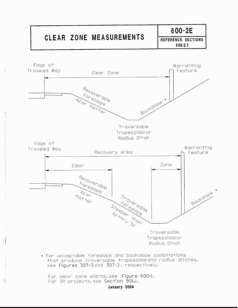


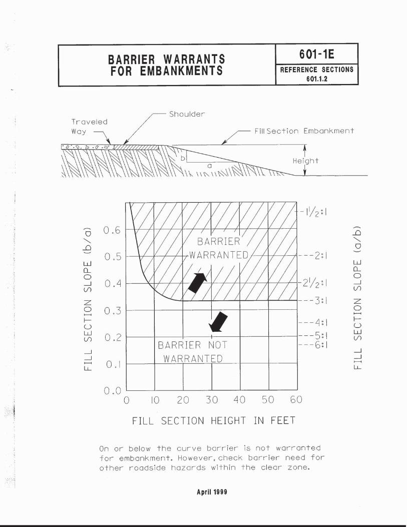


dfisher3
Typewritten Text
75
dfisher3
Typewritten Text
20:1
dfisher3
Typewritten Text
7:1
dfisher3
Typewritten Text
7:1
dfisher3
Typewritten Text
7:1
dfisher3
Typewritten Text
7:1
dfisher3
Typewritten Text
7:1
dfisher3
Typewritten Text
7:1
dfisher3
Typewritten Text
7:1
dfisher3
Typewritten Text
7:1
dfisher3
Typewritten Text
7:1
dfisher3
Typewritten Text
415
dfisher3
Typewritten Text
380
dfisher3
Typewritten Text
335
dfisher3
Typewritten Text
290
dfisher3
Typewritten Text
July 2013
dfisher3
Typewritten Text
MGS
dfisher3
Typewritten Text
Guardrail

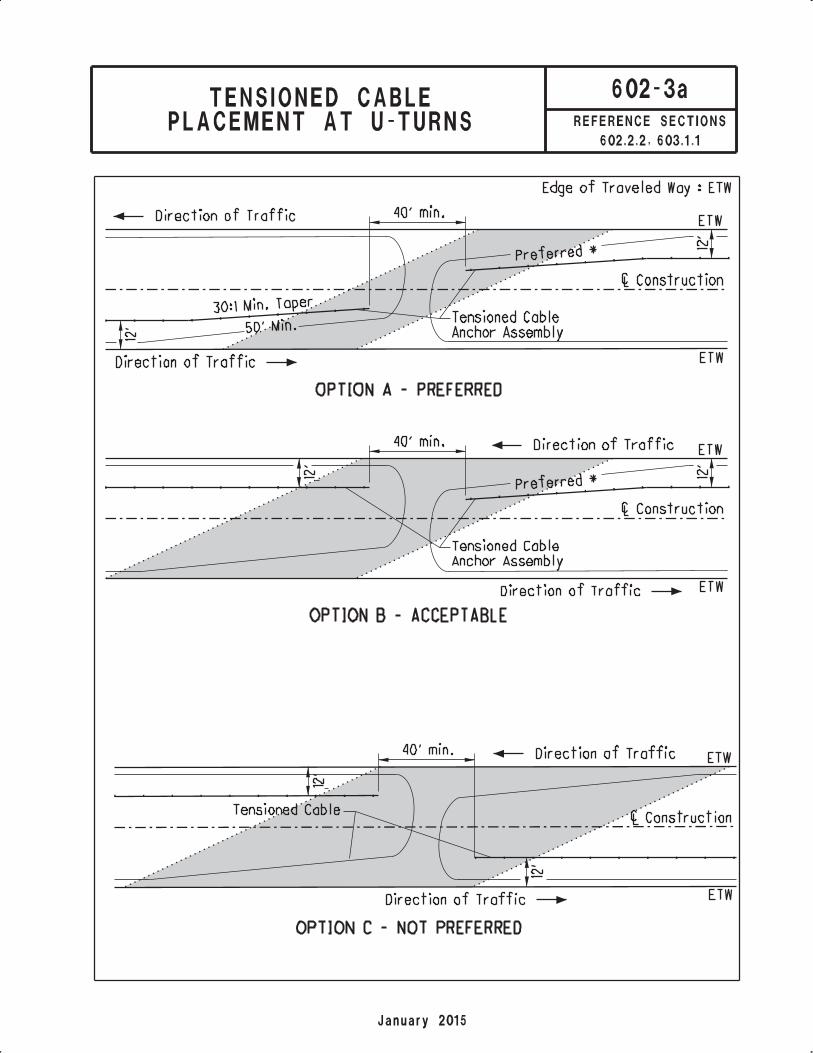
dfisher3
Typewritten Text
Shaded area represents the effective gap between cable ends
dfisher3
Typewritten Text
at the U-Turn Locations Option C Should be avoided where possible
dfisher3
Typewritten Text
unless site constraints prohibit Options A & B

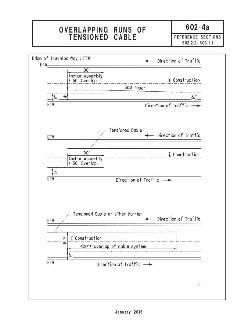
dfisher3
Typewritten Text
TENSIONED CABLE ANCHOR ASSEMBLY OVERLAP ( on same side of median )
dfisher3
Typewritten Text
TENSIONED CABLE ANCHOR ASSEMBLY OVERLAP
dfisher3
Typewritten Text
( barrier runs on opposite sides of median )
dfisher3
Typewritten Text
TENSIONED CABLE ANCHOR ASSEMBLY OVERLAP
dfisher3
Typewritten Text
dfisher3
Typewritten Text
Where transverse space between cable barrier and the opposing traffic barrier
dfisher3
Typewritten Text
exists such that a gap in cross-median protection would be created, additional
dfisher3
Typewritten Text
length of overlap between the two barriers should be considered.
dfisher3
Typewritten Text
*
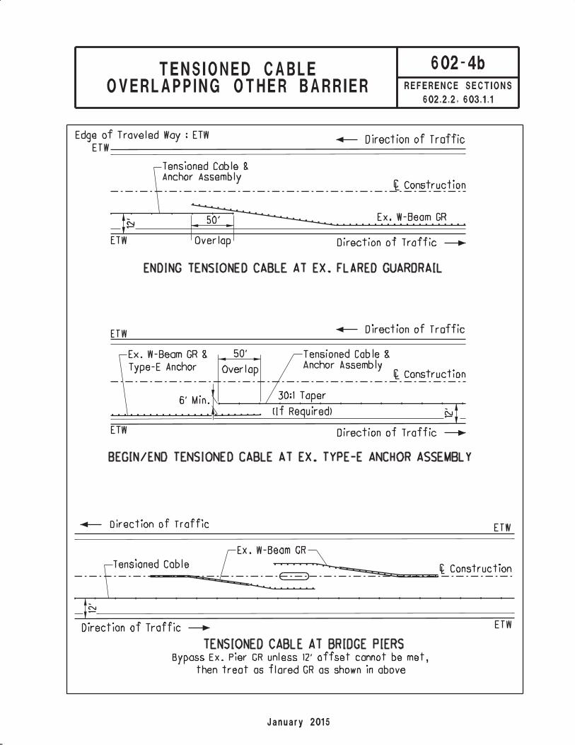
dfisher3
Typewritten Text
Where possible, preference is to overlap the trailing barrier end in front of / closer
dfisher3
Typewritten Text
to the roadway than the beginning / approach end of the second barrier.
dfisher3
Typewritten Text
Where possible, preference is to overlap the trailing barrier end in front of / closer
dfisher3
Typewritten Text
to the roadway than the beginning / approach end of the second barrier.


TYPICAL BARRIER USES & MINIMUM CLEARANCES
603-2E REFERENCE SECTIONS 602.1.1,
603.1
Barrier Type
Standard Drawing
Minimum Barrier
Clearance* Typical Use
ST
EE
L B
EA
M G
UA
RD
RA
IL
CO
NC
RE
TE
BA
RR
IER
50” PCB RM-4.1 6’-3”
32” PCB RM-4.2 5’-6”
Type B RM-4.3 Width of Barrier 28”
Narrow medians where raceways or median lighting is used.
Type B1 RM-4.3 Width of Barrier 33 3/4”
Narrow medians where additional height is required and raceways are needed.
Type C RM-4.3 Width of Barrier
Varies up to 32 3/8” Narrow medians where the difference in shoulder
elevation is 24 inches or less. Type C1 RM-4.3
Width of Barrier Varies up to 38-
1/4”
Type D RM-4.5 Width of Barrier 20”
Roadside protection adjacent to fixed obstacles. Areas where impact angles over 15 degrees are unlikely or where maintenance may be difficult/dangerous.
*Measured from the face of the barrier to the obstacle.
dfisher3
Typewritten Text
Type MGS
dfisher3
Typewritten Text
MGS-2.1
dfisher3
Typewritten Text
MGS-2.1
dfisher3
Typewritten Text
dfisher3
Typewritten Text
MGS-2.1
dfisher3
Typewritten Text
MGS-2.1
dfisher3
Typewritten Text
MGS-6.1
dfisher3
Typewritten Text
MGS-6.2
dfisher3
Typewritten Text
MGS Barrier
dfisher3
Typewritten Text
MGS Long
dfisher3
Typewritten Text
Span Across
dfisher3
Typewritten Text
Culvert
dfisher3
Typewritten Text
MGS-2.3
dfisher3
Typewritten Text
Socketed
dfisher3
Typewritten Text
Weak Post
dfisher3
Typewritten Text
Mounting
dfisher3
Typewritten Text
MGS-2.4
dfisher3
Typewritten Text
5'
dfisher3
Typewritten Text
8'
dfisher3
Typewritten Text
5'
dfisher3
Typewritten Text
1'-6"
dfisher3
Typewritten Text
2'-6"
dfisher3
Typewritten Text
5'
dfisher3
Typewritten Text
Roadside protection. 6'-3" Standard Post Spacing
dfisher3
Typewritten Text
Roadside protection adjacent to fixed objects. 3'-1 1/2"
dfisher3
Typewritten Text
Half Post Spacing
dfisher3
Typewritten Text
Roadside protection adjacent to fixed objects. 1'-6 3/4"
dfisher3
Typewritten Text
Quarter Post Spacing
dfisher3
Typewritten Text
Narrow medians where deflections can be tolerated.
dfisher3
Typewritten Text
Used primarily to span across precast structures that
dfisher3
Typewritten Text
have limited depths of cover
dfisher3
Typewritten Text
Used primarily on precast structures that have limited
dfisher3
Typewritten Text
depths of cover
dfisher3
Typewritten Text
These clearances represent unanchored PCB lateral offset to fixed objects. Can be installed with minimum 2-foot offset to MOT traffic lanes and minimum 2-foot offset to the work area.
dfisher3
Typewritten Text
July 2017


dfisher3
Typewritten Text
25'
dfisher3
Typewritten Text
25'
dfisher3
Typewritten Text
Type MGS
dfisher3
Typewritten Text
Guardrail


SAMPLE CALCULATIONS
Ex. 600-1 Clear Zone Measurement Using Slope Averaging (Traversable Ditch)
April 2012
Problem 1: Compute the safe distance from the edge of traveled way to locate a tower for lighting. The project has a design speed of 55 mph, a design year traffic volume of 3,400 ADT and the following cross section in the area where the tower is to be located:
Solution 1: Step 1 - Check the foreslope from the edge of traveled way to the backslope to determine if all intermediate foreslopes are either recoverable or non-recoverable. (See Figure 600-2.)
Since the foreslope has intermediate slopes that are recoverable (12:1 & 4:1) and non-recoverable (3:1), the clear zone may extend into the backslope if necessary.
Step 2 - Determine the weighted average of the foreslope. For sections flatter than or equal to 10:1, use a 10:1 slope. (The 12:1 shoulder slope is typically ignored; however, for this example it is included for illustrative purposes.) Decimal results of 0.5 or greater should be rounded up to the next whole numbered slope while decimal results less than 0.5 should be rounded down to the next whole numbered slope.
First, multiply the width of each slope by the rate of the slope to obtain the weighted average rise for the foreslope. Include half of the ditch bottom in the foreslope.
8' (1/10) + 6' (1/4) + (0*) + 4'/2 (1/10) = 2.5'
* Since the 3:1 foreslope is non-recoverable, it is not included.
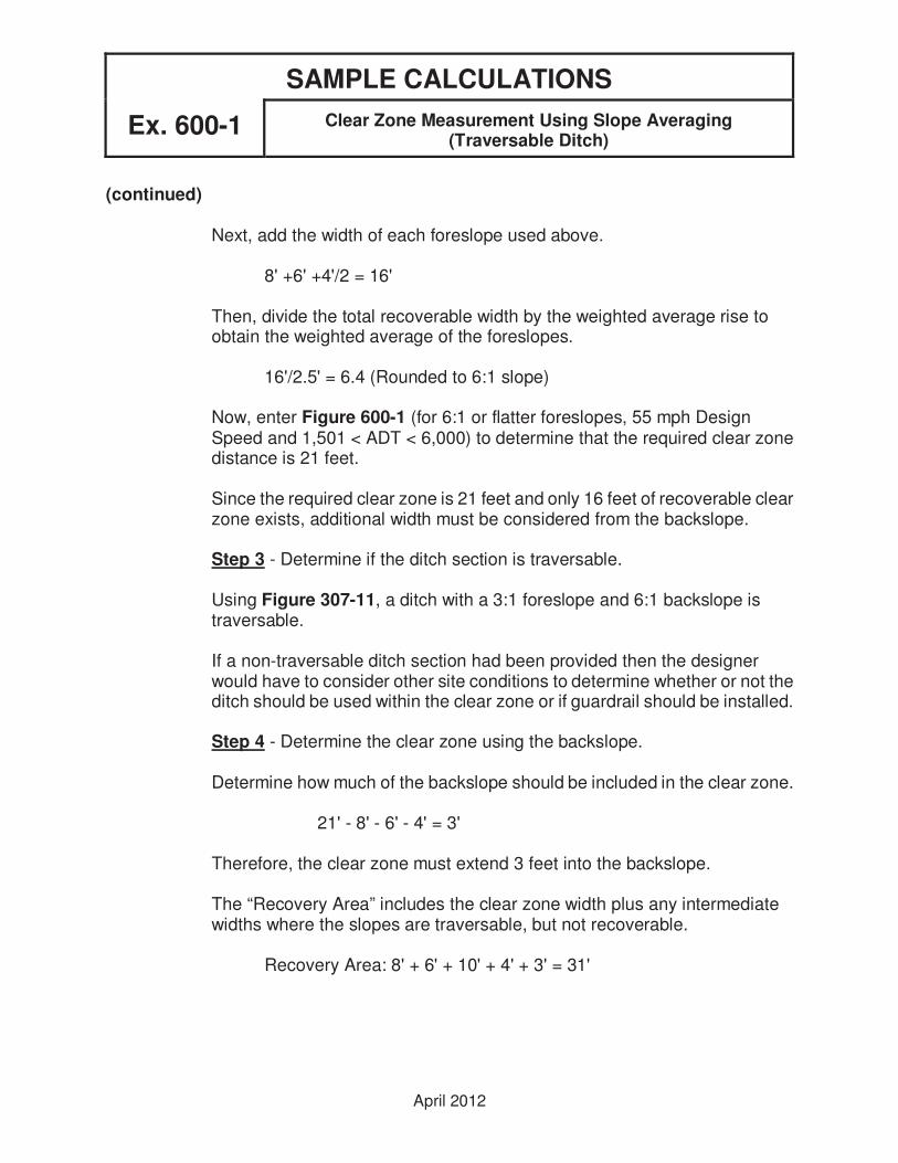
SAMPLE CALCULATIONS Ex. 600-1
Clear Zone Measurement Using Slope Averaging
(Traversable Ditch)
April 2012
(continued)
Next, add the width of each foreslope used above.
8' +6' +4'/2 = 16'
Then, divide the total recoverable width by the weighted average rise to obtain the weighted average of the foreslopes.
16'/2.5' = 6.4 (Rounded to 6:1 slope)
Now, enter Figure 600-1 (for 6:1 or flatter foreslopes, 55 mph Design Speed and 1,501 < ADT < 6,000) to determine that the required clear zone distance is 21 feet.
Since the required clear zone is 21 feet and only 16 feet of recoverable clear zone exists, additional width must be considered from the backslope.
Step 3 - Determine if the ditch section is traversable.
Using Figure 307-11, a ditch with a 3:1 foreslope and 6:1 backslope is traversable.
If a non-traversable ditch section had been provided then the designer would have to consider other site conditions to determine whether or not the ditch should be used within the clear zone or if guardrail should be installed.
Step 4 - Determine the clear zone using the backslope.
Determine how much of the backslope should be included in the clear zone.
21' - 8' - 6' - 4' = 3'
Therefore, the clear zone must extend 3 feet into the backslope.
The “Recovery Area” includes the clear zone width plus any intermediate widths where the slopes are traversable, but not recoverable.
Recovery Area: 8' + 6' + 10' + 4' + 3' = 31'

SAMPLE CALCULATIONS Ex. 600-2
Clear Zone Measurement Using Slope Averaging
(Traversable Ditch)
April 2012
Problem 2: a) Determine the required clear zone distance for the following location on a project with a tangent alignment, a design speed of 55 mph and a design year traffic volume of 1,700 ADT.
b) Assuming this cross section occurs on the outside of a 2-Degree curve, how would this change the above results?
c) Determine the clear zone distance for a Degree of Curve of 3 degrees.
Solution 2: a) - The required clear zone distance (for foreslopes steeper than 6:1 up to
4:1, 55 mph design speed, and 1,501≤≤≤≤ADT≤≤≤≤6,000) is 27 feet. 19 feet of clear distance is available up to the center of the ditch. A trapezoidal ditch with a 4:1 foreslope, 2:1 backslope and a width equal to or greater than 4 feet is a non-traversable design (see Figure 307-11) and generally should not be located within the clear zone. However, if the probability of encroachment is low no additional improvement may be needed.
b) - Since this location is on the outside of a curve where the probability of encroachment is high, the designer should consider reshaping the ditch or installing guardrail.
c) - The required clear zone distance determined above for a tangent alignment needs to be increased by a factor or 1.2 for locations on the outside of curves with a curvature of 3 degrees and a design speed of 55 mph. (See Figure 600-1.) The adjusted clear zone distance is 27 (1.23) = 33.2'. Since the adjusted value is greater than 30', use 30'. Since 19 feet or only 63% of the required clear zone distance exists on the outside of this curve, the designer should consider reshaping the ditch or installing guardrail.

SAMPLE CALCULATIONS Ex. 600-3
Clear Zone Measurement For a Cut Slope
April 2012
Problem 3: Determine the required clear zone distance for the following location on a project with a design speed of 45 mph and a design year traffic volume of 1,300 ADT.
Solution 3: The required clear zone distance (for backslopes steeper than 6:1 up to 4:1,
45 mph design speed and 750≤≤≤≤ADT≤≤≤≤1,500) is 13 feet. (See Figure 600-1.) The required clear zone is 13 feet but only 12 feet exist. If this section of roadway has a history of accidents with the cut face then guardrail should be installed.

SAMPLE CALCULATIONS Ex. 602-1
Tangent Barrier Design For a 2-lane Road
April 2012
Problem 1: Design barrier if needed to shield the fixed object located on the two-lane non-NHS rural collector shown below. The project has a design speed of 60 mph, a design year traffic volume of 2,200 ADT and a 6:1 foreslope. Assume that the object cannot be removed, relocated or made traversable.
Solution 1: Step 1 - Determine whether or not the fixed object is in the clear zone for
adjacent traffic. Refer to Figure 600-1 (for 6:1 or flatter foreslope, 60 mph
design speed and 1501≤ADT≤6000) to determine that the required clear zone distance is 28 feet.
The available clear area for adjacent traffic is 10' + 4' = 14 ft.
Since the object cannot be removed, relocated or made traversable and it is inside the required clear zone, a barrier should be installed to shield it.

SAMPLE CALCULATIONS Ex. 602-1
Tangent Barrier Design For a 2-lane Road
April 2012
(continued)
Step 2 - Select the type of barrier to be installed. Using Figure 301-3, the normal (minimum) barrier offset for a rural collector (Design Year ADT greater than 2000) is 8 feet from the edge of traveled way. The available barrier clearance at this location is (10' - 8') + 4' = 6 ft; therefore, use Type 5 Guardrail which has a minimum barrier clearance of 5.5 feet. (See Figure 603-2.)
Step 3 - Calculate the length of need for adjacent traffic. Assume the area along the front of the fixed object cannot be graded to provide 10:1 foreslopes; therefore, the guardrail cannot be installed with a flare.

SAMPLE CALCULATIONS Ex. 602-1
Tangent Barrier Design For a 2-lane Road
April 2012
(continued)
From Figure 602-1, LR = 210 ft. (for design speed = 60 mph and
1000≤ADT≤5000). Since the lateral offset to the back of the object (LH) is less than the required clear zone distance (LC), use LH in the LON formula.
x = LH + L1b/a - L2
b/a + LH/LR
Start measuring the length of guardrail needed at the edge of the fixed object. Since the guardrail will not be flared, b/a = 0.
x (adjacent) = 25.5 + 0 - 8 = 144.12 ft.
0 + 25.5/210
Step 4 - Determine whether or not the fixed object is in the clear zone for opposing traffic. The required clear zone is still 28 feet. The available clear area is 12' (lane width) + 14' = 26 ft. Since the object is in the clear zone, calculate the offset to the back of the object, LH.
LH = 12' + 14' + 11.5' = 37.5 ft.
Since LH>LC, protection only needs to be provided up to the clear zone.
x (opposing) = LC + L1b/a - L2 = 28' + 0 - 20' = 60.00 ft. b/a + LC/LR 0 + 28/210

SAMPLE CALCULATIONS Ex. 602-1
Tangent Barrier Design For a 2-lane Road
April 2012
(continued)
The total length of guardrail required is:
x(adjacent) + width of object + x(opposing) = 144.12+ 5' + 60.00' = 209.12ft.
The length provided should be a multiple of even 12'-6" panel lengths.
x = 209.12'/12.5' = 16.73 Use 17 panels or 17(12.5') = 212.5 ft.
Note - If the designer had chosen to shield the entire object from opposing traffic instead of providing protection up to the clear zone, then
x(opposing) = LH - L2 = 37.5 – 20 = 98 ft. LH/LR
37.5/210
The total length of guardrail needed would have been:
144.12' + 5' + 98' = 247.12 ft. (or 20 panels)
Three additional panels (37.5 feet) of guardrail would be installed. In some cases, the designer may choose to shield the entire object even though a portion of it is outside the clear zone; however, in some cases it may be uneconomical to do so.
Step 5 - Select Anchor Assemblies. Since this is a non-NHS collector with
a design year ADT≤4000, a Type A Anchor Assembly may be installed on the approach and trailing ends of the guardrail run.

SAMPLE CALCULATIONS Ex. 602-2
Length of Need at a Large Culvert
April 2012
Problem 2: Design barrier if needed to shield the culvert headwalls located on the two-lane non-NHS rural collector shown below. This bridge replacement project has a design speed of 55 mph, a design year traffic volume of 4,100 ADT and 4:1 foreslopes.
Solution 2 Step 1 - Determine whether or not the headwall is in the clear zone for
adjacent traffic. Refer to Figure 600-1 (for foreslopes steeper than 6:1 up
to 4:1, 55 mph design speed and 1501≤ADT≤6000) to determine that the required clear zone distance is 27 feet measured from the edge of traveled way.
The available clear area for adjacent traffic is 26' - 12' - 1'-6" = 12'-6".
It is impractical to almost double the length of the culvert to get the headwalls outside the clear zone; therefore, barrier should be provided.
Step 2 - Select the type of barrier to be installed. Using Figure 301-3, the normal barrier offset for a rural collector (Design Year ADT greater than 2000) is 10' from the edge of traveled way. The available barrier clearance at this location is (12' - 10') + (2' - 1.5') = 2.5 ft.

SAMPLE CALCULATIONS Ex. 602-2
Length of Need at a Large Culvert
April 2012
(continued)
Since there is not enough clearance available for Type 5 Guardrail, which has a minimum barrier clearance of 5'-6", use Type 5 Guardrail with Tubular Backup, which has a minimum barrier clearance of 24.” (See Figure 603-2.)
Step 3 - Calculate the length of need for adjacent traffic. Since the foreslope along the face of the fixed object cannot be regraded to 10:1, do not flare the guardrail. (The geometrics of the roadway and the offset to the headwall are the same on both sides of the road; therefore, the lengths calculated for adjacent and opposing traffic for the eastbound lane will be the same as those calculated for adjacent and opposing traffic for the westbound lane.)

SAMPLE CALCULATIONS Ex. 602-2
Length of Need at a Large Culvert
April 2012
(continued)
From Figure 602-1, LR = 185 ft. (for design speed = 55 mph and
1000≤ADT≤5000). Since the lateral offset to the back of the headwall (LH) is less than the required clear zone distance (LC), use LH in the LON formula.
x = LH + L1b/a - L2
b/a + LH/LR
Start measuring the length of guardrail needed at the edge of the headwall. Since the guardrail will not be flared, b/a = 0.
x (adjacent) = 14' + 0 - 10' = 52.85 ft.
0 + 14'/185'
Step 4 - Determine whether or not the headwall is in the clear zone for opposing traffic. The required clear zone distance is still 27 feet. The available clear area is 26' - 1'-6" = 24'-6".
Since LH<LC, x = LH + L1b/a - L2 b/a + LH/LR
Start measuring the length of guardrail needed at the edge of the headwall. Since the guardrail will not be flared, b/a = 0.
x (opposing) = 26' + 0 - 22' = 28.46 ft.
0 + 26'/185'

SAMPLE CALCULATIONS Ex. 602-2
Length of Need at a Large Culvert
April 2012
(continued)
The total length of guardrail required is:
x(adjacent) + width of headwall + x(opposing) = 52.85' + 26' + 28.46' = 107.32 ft.
The length provided should be a multiple of even 12'-6" guardrail panel lengths.
x = 107.32/12.5 = 8.59 Use 9 panels or 9(12.5') = 112.5 ft.
Step 5 - Detail the final installation, including the anchor assemblies. The Type 5 Guardrail with Tubular Backup should extend to the first post off the approach and trailing ends of the structure. In this case, the headwall (not the culvert itself) is the structure that is being protected. This headwall is slightly longer than 2 panels of guardrail so use 3 panels (37'-6"). A Type 4 Bridge Terminal Assembly is required at each end of the Type 5 Guardrail with Tubular Backup. This 25’ long transition is paid for as a unit and its length can be included as part of the total of Type 5 Guardrail being installed.
Type A Anchor Assemblies are not permitted because the design year ADT is over 4000. See Section 603.3.4. Refer to Table 603-1 in Section 603.3.3 for a Bridge Replacement Project with foreslopes steeper than 6:1 up to 4:1 to determine that a Type E Anchor Assembly should be used on the approach and trailing ends. (It is required on the trailing end because it is within the clear zone for opposing traffic.)
Since up to 37'-6" of the 50' long Type E can be deducted from the guardrail length of need, decrease the amount of rail specified for the approach end by this amount. In this case, the 25’ of the BTA + the 37.5’ of the Type E + 5.75’ Tubular Backup = 68.25’, which exceeds the 52.85’ LON. On the trailing end the amount of barrier included in the Bridge Terminal Assembly and the Type E also exceeds the 28.46’ LON. (See the following final detail.)
Note: Many large culverts are located in deep channels with steep side slopes.
This may necessitate that the designer use LH = LC when calculating the required length of need.
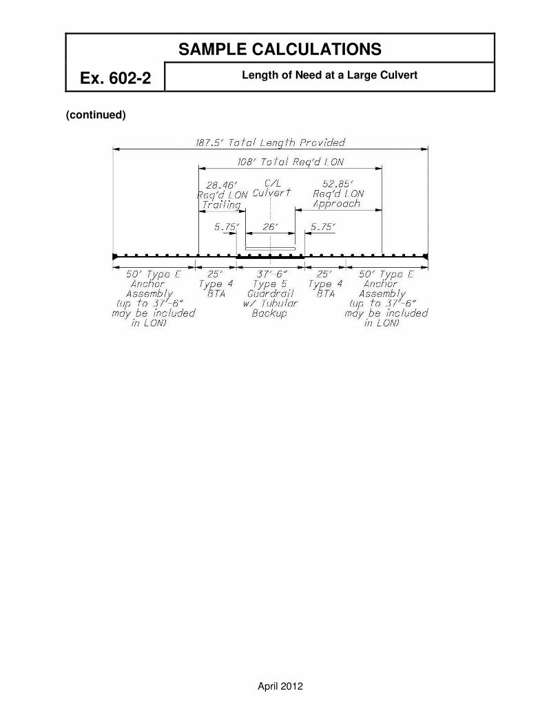
SAMPLE CALCULATIONS Ex. 602-2
Length of Need at a Large Culvert
April 2012
(continued)

SAMPLE CALCULATIONS Ex. 602-3
Tangent and Flared Barrier Design For a Divided Highway
April 2012
Problem 3: Design barrier if needed to shield the 3' diameter footing located on the
4-lane, divided, NHS, urban, interstate reconstruction project shown below. The project has a design speed of 70 mph, a design year traffic volume of 12,000 ADT and 10:1 foreslopes. If barrier is needed calculate how much should be provided if it is installed a) at the normal (minimum) barrier offset on a tangent, b) at the normal (minimum) barrier offset on a flare, c) as close to the footing as permissible on a tangent and d) as close to the footing as permissible on a flare.
Solution 3: Step 1 - Determine whether or not the footing is in the clear zone for
adjacent traffic. Refer to Figure 600-1 (for foreslopes 6:1 or flatter, 70 mph design speed and ADT>6000) to determine that the required clear zone distance is 32 feet measured from the edge of traveled way. However, since this is not a high accident area a maximum clear zone distance of 30' should be used.
The available clear area for adjacent traffic is 15' + 12' = 27'
Assuming the footing cannot be relocated outside the clear zone, barrier should be provided.
Step 2 - Select the type of barrier to be installed. Using Figures 301-4 & 301-3, the normal (minimum) barrier offset for an urban interstate route is 12' from the right edge of traveled way. The available barrier clearance at this location is 3' + 12' = 15'; therefore, use Type 5 Guardrail, which has a minimum barrier clearance of 5.5'. (See Figure 603-2.)

SAMPLE CALCULATIONS Ex. 602-3
Tangent and Flared Barrier Design For a Divided Highway
April 2012
(continued)
Step 3 - Calculate the length of need for adjacent traffic. (A calculation for opposing traffic is unnecessary because the concrete median barrier prevents encroachments by opposing vehicles.)
From Figure 602-1, LR = 360 ft. (for Design Speed = 70 mph and ADT over 10000).
a) For tangent guardrail at the normal (minimum) barrier offset, LH=LC=30', L2=12', and b/a = 0.
x = LH + L1b/a - L2 = 30' + 0 - 12' = 216' Use 18 panels. b/a + LH/LR 0 + 30'/360’
b) For flared guardrail at the normal (minimum) barrier offset, b/a = 1/15. (See Figure 602-1.) Let L1=12'-6" (one panel length). In this case, this is an arbitrary selection. Site conditions typically control the amount of tangent barrier that should be provided past the warranting feature before a flare is introduced. For instance, where a flared section of Type 5 Guardrail is attached to a tangent section of Type 5A, it is advisable to extend the Type 5A past the warranting feature such that L1 is at least equal to one panel length. Since Type 5 and 5A have different deflection characteristics, this ensures adequate protection at the edge of the warranting feature.
x = 30' + 12.5'(1/15) - 12' = 30' + 0.83' - 12' = 125.55' Use 10 panels. 1/15 + 30'/360' 0.15'
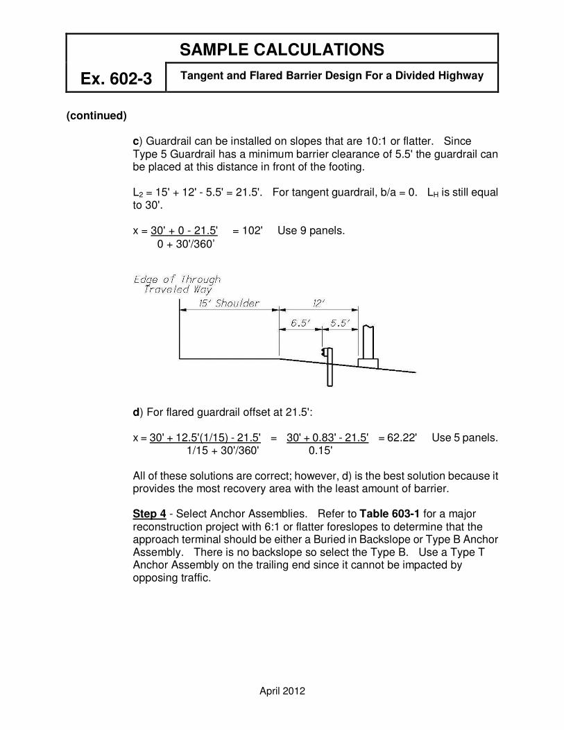
SAMPLE CALCULATIONS Ex. 602-3
Tangent and Flared Barrier Design For a Divided Highway
April 2012
(continued)
c) Guardrail can be installed on slopes that are 10:1 or flatter. Since Type 5 Guardrail has a minimum barrier clearance of 5.5' the guardrail can be placed at this distance in front of the footing.
L2 = 15' + 12' - 5.5' = 21.5'. For tangent guardrail, b/a = 0. LH is still equal to 30'.
x = 30' + 0 - 21.5' = 102' Use 9 panels. 0 + 30'/360’
d) For flared guardrail offset at 21.5':
x = 30' + 12.5'(1/15) - 21.5' = 30' + 0.83' - 21.5' = 62.22' Use 5 panels. 1/15 + 30'/360' 0.15'
All of these solutions are correct; however, d) is the best solution because it provides the most recovery area with the least amount of barrier.
Step 4 - Select Anchor Assemblies. Refer to Table 603-1 for a major reconstruction project with 6:1 or flatter foreslopes to determine that the approach terminal should be either a Buried in Backslope or Type B Anchor Assembly. There is no backslope so select the Type B. Use a Type T Anchor Assembly on the trailing end since it cannot be impacted by opposing traffic.

SAMPLE CALCULATIONS Ex. 602-4
Barrier on the Outside of a Curve
April 2012
Problem 4: Calculate the barrier length of need to shield the 200-yr old 5-ft. diameter tree located on the outside of a 3-degree curve as shown below. The HSP project is on a rural arterial and has a design speed of 55 mph, a design year traffic volume of 3800 ADT and 5:1 foreslopes. Assume that the HSP project is needed to address run-off-the-road impacts with the tree and also assume that the tree cannot be removed.
Solution 4: Step 1 - Determine whether or not the tree is in the clear zone for adjacent
traffic. From Figure 600-1 (for foreslopes steeper than 6:1 up to 4:1,
55 mph design speed and 1501≤ADT≤6000) the required clear zone distance is 27 feet measured from the edge of traveled way. Since the tree is on the outside of a 3-degree curve, the clear zone should be widened by using the curve correction factor for 55 mph design speed (1.2) from the chart at the bottom of Figure 600-1.
Required Clear Zone = 1.23 (27') = 33.21 ft.
Do not reduce this value to 30 ft. since this is a high accident location.
The offset to the face of the tree is 12' + 10' = 22 ft. This is less than LC = 33.21 ft.; therefore, install barrier.

SAMPLE CALCULATIONS Ex. 602-4
Barrier on the Outside of a Curve
April 2012
(continued) Step 2 - Select the type of barrier to be installed. Using Figure 301-3, the normal (minimum) barrier offset for a rural arterial (Design year ADT greater than 2000) is 10 feet from the right edge of traveled way. The available barrier clearance at this location is 12 feet; therefore, use Type 5 Guardrail, which has a minimum barrier clearance of 5.5 feet. (See Figure 603-2.)
Step 3 - Calculate the length of need for adjacent traffic. The radius for the 3-degree curve is Rcenterline = 5729.58/DC = 5729.58/3.0 = 1909.86'.
The radius at the edge of traveled way is 1909.86' + 12' =1921.86'.
The lateral offset to the back of the tree is, LH = 22' + 5' =27'.
θ1 = cos-1 (Radj / (Radj + LH)) = cos-1 (1921.86 / (1921.86 + 27)) = 9.5484°
9.5484°(π/180) = 0.1666 radians
θ2 = cos-1 (Radj / (Radj + L2)) = cos-1 (1921.86 / (1921.86 + 10)) = 5.8323°
5.8323°(π/180) = 0.1018 radians
X = (Radj + L2) (θ1 - θ2) rad. = (1921.86 +10) (0.1666 - 0.1018) = 125.18'

SAMPLE CALCULATIONS Ex. 602-4
Barrier on the Outside of a Curve
April 2012
(continued)
Step 4 - Determine whether or not the tree is within the clear zone for opposing traffic. The offset to the face of the tree is 12' + 12' + 10' = 34'. Since this is outside the clear zone, guardrail is not needed past the left side of the tree to shield it from opposing traffic.
The total length of guardrail needed is 125.18' + 5' = 130.18' Use 11 panels (137.5').
Refer to Table 603-1 in Section 603.3.3 to determine the recommended anchor assembly for an HSP project with foreslopes steeper than 6:1 up to 4:1. On the approach end install a Type E Anchor Assembly. Since 37'-6" of the 50' long Type E can be deducted from the guardrail length of need, decrease the amount of rail specified above at the approach end by this amount. (Use 100'.) On the trailing end install a Type T Anchor Assembly because it is outside the clear zone for opposing traffic.
Notes - If a point of curvature exists in the vicinity of the runout path, the curve may need to be extended past the PC or PT (into the tangent portion of the roadway) in order to construct the tangent control line. If this is the case, then the standard runout lengths for tangent roadways should be used to calculate length of need.