6.0 ENGINE COOLING SYSTEMS If this heat is not removed ... · pump draws suction on the system and...
11
Emergency Diesel Generator Engine Cooling Systems Rev 1/11 6-1 of 11 USNRC HRTD 6.0 ENGINE COOLING SYSTEMS This chapter identifies the major components of the diesel engine cooling systems and explains how each system is necessary for reliable operation of the engine. Learning Objectives As a result of this lesson, you will be able to: 1. State the purpose of a diesel engine jacket water cooling system. 2. Identify the major components of a typical diesel engine jacket water cooling system and describe the operation of each. 3. State the purpose and describe the operation of the jacket water keepwarm and circulation system as is commonly used on nuclear application diesel engines. 4. State the purpose of a diesel engine intercooler (aftercooler) water cooling system. 5. Identify the major components of a typical diesel engine intercooler water system and describe the operation of each. 6. Identify other cooling requirements, such as engine room cooling. 6.1 Engine Cooling Approximately 25 to 30 percent of the total heat input to the engine supplied by the fuel is absorbed by the engine cooling system. If this heat is not removed, engine internal temperatures would soon reach a point of component damage and engine failure. All commercial diesel engines use some form of cooling system to absorb this heat and transfer it to a heat absorbing medium outside of the engine. Many modern engines are equipped with turbocharging systems to provide enough air to allow the burning of the fuel required to produce the required power. The turbocharging system adds heat to the combustion air. In order to ensure that sufficient pounds of air are provided for the combustion of the fuel, it is necessary to cool the combustion air before it goes into the engine cylinders (to maintain the air density). This is done by means of a radiator-like heat exchanger called the air intercooler, or aftercooler, and mounted in the piping between the turbocharger compressor outlet and the engine air manifold. This radiator removes excess heat from the combustion air. Water from either the jacket water system or from the service water system (the ultimate heat sink) may be used in this heat exchanger. When service water is used, there may be an additional heat exchanger between the service water system and the intercooler water system so that the water in the intercooler system can be treated and maintained in a state that will not contribute to the deterioration of the air intercooler. 6.1.1 Cooling System Basics Most diesel engines use a closed loop jacket type cooling system. Coolant flows through the engine absorbing heat from the cylinder liners, cylinder heads, and other engine components.
Transcript of 6.0 ENGINE COOLING SYSTEMS If this heat is not removed ... · pump draws suction on the system and...

Emergency Diesel Generator Engine Cooling Systems
Rev 1/11 6-1 of 11 USNRC HRTD
6.0 ENGINE COOLING SYSTEMS This chapter identifies the major components of the diesel engine cooling systems and explains how each system is necessary for reliable operation of the engine. Learning Objectives As a result of this lesson, you will be able to: 1. State the purpose of a diesel engine
jacket water cooling system. 2. Identify the major components of a
typical diesel engine jacket water cooling system and describe the operation of each.
3. State the purpose and describe the
operation of the jacket water keepwarm and circulation system as is commonly used on nuclear application diesel engines.
4. State the purpose of a diesel engine
intercooler (aftercooler) water cooling system.
5. Identify the major components of a
typical diesel engine intercooler water system and describe the operation of each.
6. Identify other cooling requirements,
such as engine room cooling. 6.1 Engine Cooling Approximately 25 to 30 percent of the total heat input to the engine supplied by the fuel is absorbed by the engine cooling system.
If this heat is not removed, engine internal temperatures would soon reach a point of component damage and engine failure. All commercial diesel engines use some form of cooling system to absorb this heat and transfer it to a heat absorbing medium outside of the engine. Many modern engines are equipped with turbocharging systems to provide enough air to allow the burning of the fuel required to produce the required power. The turbocharging system adds heat to the combustion air. In order to ensure that sufficient pounds of air are provided for the combustion of the fuel, it is necessary to cool the combustion air before it goes into the engine cylinders (to maintain the air density). This is done by means of a radiator-like heat exchanger called the air intercooler, or aftercooler, and mounted in the piping between the turbocharger compressor outlet and the engine air manifold. This radiator removes excess heat from the combustion air. Water from either the jacket water system or from the service water system (the ultimate heat sink) may be used in this heat exchanger. When service water is used, there may be an additional heat exchanger between the service water system and the intercooler water system so that the water in the intercooler system can be treated and maintained in a state that will not contribute to the deterioration of the air intercooler. 6.1.1 Cooling System Basics Most diesel engines use a closed loop jacket type cooling system. Coolant flows through the engine absorbing heat from the cylinder liners, cylinder heads, and other engine components.

Emergency Diesel Generator Engine Cooling Systems
Rev 1/11 6-2 of 11 USNRC HRTD
6.1.1.1 Coolant Temperature - As a general rule, the higher the temperature of the coolant leaving the engine, the more efficiently the engine will operate. On the other hand, extremely high coolant temperatures can allow overheating of engine components which could cause structural damage. Jacket water may also be used to cool the lubricating oil through a heat exchanger. For most diesel engines, a jacket water discharge temperature of about 180oF is preferred with a temperature rise through the engine in the range of 8 to15oF. 6.1.1.2 Engine Coolant - Water is the most common coolant used in diesel engines. However, water alone presents the possibility of corrosion, mineral deposits, and freezing. Where engines could be subjected to temperatures near or below freezing, an antifreeze such as ethylene glycol or propylene glycol must be added. The most common solution is a 50/50 mix of antifreeze and water, which is good for temperatures down to -40oF. Commercial antifreeze includes corrosion inhibitor additives. Adding antifreeze does negatively affect heat transfer. Diesel engines used for emergency service at nuclear facilities are not generally subjected to temperatures where freezing is a possibility. Under these conditions, use of antifreeze is not required. However, the corrosion inhibitor additives can be mixed with demineralized water to provide corrosion protection. 6.1.1.3 Water Chemistry - The water used for engine coolant should be clean
and free of deposits or scale forming substances. De-mineralized water is most frequently used. The water should be slightly alkaline, specifically meaning a pH of 8 to 9.5. Addition of a corrosion inhibitor such as Nalco 2000 is recommended to prevent the build-up of scale on cylinder liners and cylinder heads. One sixteenth inch of scale is like adding one inch of steel with respect to the resistance to heat transfer from the engine. Periodic chemical analysis of the coolant is performed and corrective amounts of corrosion inhibitor added to maintain proper water chemistry. 6.1.2 Engine Cooling Systems A typical closed loop diesel engine cooling system is shown in Figure 6-1. In the following discussion, the word 'radiator' could be substituted for 'heat exchanger' on engines equipped with a radiator. On some units, there are separate radiator sections for cooling the intercooler water and the jacket water. In such cases, the lube oil is typically cooled from the jacket water circuit. Coolant is stored in the engine system itself with the assistance of an expansion tank (head or make-up tank) which is mounted at a point above the engine to maintain a head on the system. The engine-driven pump draws suction on the system and delivers the coolant to the engine. In most systems, the water exits the engine and goes through a thermostatically controlled valve. From the valve, the water either goes through the heat exchanger, if the water is hot, or through a bypass line

Emergency Diesel Generator Engine Cooling Systems
Rev 1/11 6-3 of 11 USNRC HRTD
around the heat exchanger when the water is too cold. The thermostatic control valve (TCV) senses and reacts to coolant temperature. When the temperature of the engine coolant is below the set-point of the valve, coolant is bypassed around the jacket water heat exchanger. When the coolant temperature is above the set-point, the valve directs the coolant through the heat exchanger where the excess heat is transferred to the raw or service water system. Service water flow is automatically initiated upon any type of diesel engine start. From the outlet of the heat exchanger, or bypass line, the water returns to the jacket water pump and thereby to the engine. In many systems, the lube oil system is cooled by a heat exchanger in the jacket water system. On engines where it is desirable to keep the lube oil at a temperature lower than that in the jacket water system, the oil heat is transferred directly to the service/raw water system through the lube oil system heat exchanger as shown in Chapter 5. As the coolant enters the cylinder block, it is directed by internal passages and/or piping to the lower end of the cylinder liners. The fluid flows around the cylinder liners moving upward and into the cylinder heads. The coolant leaving the cylinder heads passes into an outlet header and to the thermostatic valve. On some engines equipped with inter-coolers or aftercoolers, a portion of the jacket water passes through the intercoolers absorbing the excess heat
from the incoming air charge. On many engines with intercoolers or aftercoolers, a separate heat exchanger passes this excess heat to the service/raw water system. This is most desirable in as much as it is best to cool the intercooler water to a temperature below that of the jacket water system. ALCO engines generally use the jacket water system to cool the intercooler water. 6.1.2.1 Expansion Tank - Many engine use an expansion tank with a pressurized closure, or the expansion tank is mounted high enough to maintain the necessary head (net positive pressure head - NPSH) on the system. The expansion tank is usually located slightly above the highest point in the jacket cooling water system and vent lines are used to continuously purge air from the system. Some expansion tanks may be pressurized to maintain a higher pressure which is helpful in raising the boiling point of the cooling fluid. 6.1.2.2 Standpipe - A standpipe is a vertical tank mounted at the same elevation as the engine. It stores engine coolant while providing an air space to compensate for thermal expansion of the coolant. Standpipes are generally vented to the atmosphere providing a non-pressurized cooling system. The level of water in the standpipe must be such as to provide a proper NPSH, or the tank must be pressurized. 6.1.2.3 Jacket Water Pump - The engine-driven jacket water pump, shown in Figure 6-2, is a single stage centrifugal pump driven by the engine’s crankshaft through a series of gears.

Emergency Diesel Generator Engine Cooling Systems
Rev 1/11 6-4 of 11 USNRC HRTD
Water enters the inlet of suction of the pump as shown. The pump drive gear, being driven by the engine gear train, causes the pump shaft and impeller to rotate. Rotation of the impeller throws the coolant outward, increasing its velocity by centrifugal force. As the coolant enters the pump casing, its velocity decreases with a corresponding increase in pressure. The coolant, now at an increased pressure, discharges from the pump casing into the jacket water header to the lower end of the cylinder liners. 6.1.2.4 Thermostatic Control Valve - The thermostatic control valve shown in Figure 6-3 is typical of those used on large diesel engines in nuclear service. Engine coolant enters the valve at the bottom. When the coolant temperature is low, the sliding valve poppet remains in the upward position, as shown on the right part of the diagram, and bypasses the coolant around the heat exchanger. As the coolant temperature increases, wax pellets inside the temperature control elements expand, pushing the element tube and sliding the valve poppet down. As this happens, bypass flow is blocked or throttled, as shown on the left portion of the diagram, and the coolant is directed to the heat exchanger. In operation, the valve modulates over a temperature of about 10 to 15oF to balance flow between the heat exchanger and bypass to maintain a fairly constant coolant temperature. 6.1.2.5 Jacket Water Heat Exchanger - Jacket water heat exchangers are typically of the shell and tube type, similar to that
shown in Chapter 5. Generally, engine coolant passes over the tubes in the shell side while service water passes through the tubes. 6.1.3 Jacket Water Keepwarm Systems When an engine has been shut down for a period of time, the temperature of the engine internals drops substantially. The rapid start and fast loading of a cold engine, typical of a nuclear application diesels under emergency conditions, causes high stress and increased wear until the engine reaches its normal operating temperature. The jacket water keepwarm system is shown along with the normal jacket water cooling system on the same schematic in Figure 6.1. This system functions to keep the overall temperature of the engine coolant at or near its normal operating temperature. This is not to say that each component is at its normal temperature. Since diesel engines rely on the heat of compression for ignition, keeping the engine warm substantially decreases the start time and reduces the chances of a failure to start because of low intake air temperature. 6.1.3.1 Keepwarm Pump - The keepwarm pump is an electrically driven, single stage centrifugal pump similar to the engine-driven pump, which maintains the flow of heated coolant through the engine while the engine is shutdown. 6.1.3.2 Keepwarm Heater - Like the lube oil keepwarm heater, the jacket waterkeep warm heater is an electric immersion type. It is mounted in the standpipe or separate

Emergency Diesel Generator Engine Cooling Systems
Rev 1/11 6-5 of 11 USNRC HRTD
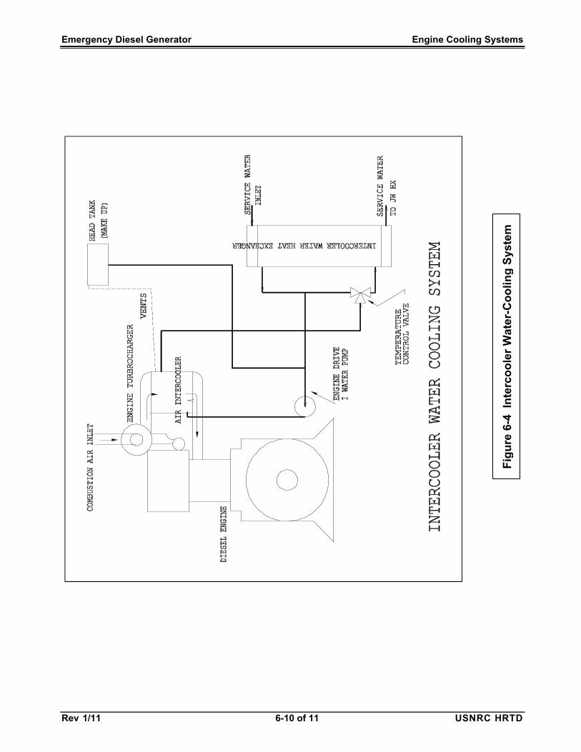
heating tank. It is thermostatically controlled to maintain the engine at the desired temperature. 6.1.3.3 System Operation - When the engine is in the standby mode, the keepwarm system is energized. The keepwarm pump draws a suction on the system and discharges water into the jacket water inlet to the engine. There may be check valves installed to prevent reverse flow in the keepwarm system when the engine is operating. The heated coolant flows through the engine warming the cylinders, cylinder heads, and other water-cooled engine components. 6.2 Intercooler Water System The intercooler water system supplies water to the intercooler or aftercooler mounted in the engine’s combustion air inlet piping. It is a radiator like heat exchanger that cools the combustion air after the turbocharger compressor and before the engine’s air manifold /plenum. Cooling increases the density of the air, thereby providing more oxygen to burn more fuel for higher power output. The combustion air also provides cooling for the piston crowns. The water for the intercooling generally needs to be very near atmospheric air temperature. Therefore, it is usually desirable to use service water to do this cooling rather than jacket water, which is at a much higher temperature (160 to 180oF). A typical schematic for the intercooler/ aftercooler water system is shown in Figure 6.4. The components in this system are
very similar to those used in the jacket water system and will not be detailed further here. In some intercooler water systems, there may be a thermostatic control used to keep the intercooler water from getting too cold, especially in cold weather or when the engine is at light load, to keep condensation of moisture in the combustion air to a minimum. In a few systems, there is an interconnection between the jacket water system and the intercooler water system to assist in heating the intercooler when required. Engine start time, light load performance, and cylinder liner lubrication may be degraded if the inlet combustion air is too cold. To minimize the effect, some manufacturers thermostatically throttle cooling water to the intercooler and/or provide heated jacket water to the cooler when required. The purpose of the thermostatic valve in the circuit shown in Figure 6-4 is to keep the intercooler water (and thus the air into the engine) from being too cold. This can cause condensation in the engine as well as 'white' smoke in the exhaust when the air to too cold. 6.3 Other Cooling Requirements The diesel generator unit is typically housed in a building that has few openings. There are a number of sources of heat within the EDG room including the engine and generator. Some of the equipment in this room such as the switchgear, control panels, monitoring equipment, fuel day tank, air compressor(s), and air storage

Emergency Diesel Generator Engine Cooling Systems
Rev 1/11 6-6 of 11 USNRC HRTD
tank(s) must be kept cool to work properly. The usual limit for the temperature within the EDG room is 122oF (50oC). Therefore, it is necessary to bring enough cool air (ambient air) into this space to remove the heat and keep the room below the maximum allowable temperature. While the engine itself is not severely affected by the temperature within the room, the generator and other components can be impacted by excessively high EDG room temperatures. If the engine combustion air is taken from within the room, too high a temperature of inlet air to the engine can affect the engine’s ability to produce power. The following list gives the sources of heat within the EDG room (in order of usual magnitude). • Radiation from the engine -
approximately 2% of the value of the heat content of the fuel input to the engine.
• Radiation from the generator – this is
approximately equal to the inefficiency of the generator, or 3 to 5% of the generator rated KVA (KW).
• Radiation for the excitation equipment -
approximately 0.5% of the generator rated KVA (KW).
• Radiation from engine exhaust piping. • Radiation from switch gear, cabling,
transformers, etc. in the electrical system.
EDG room coolers may be required if ambient outside air cooling is not adequate.

Emergency Diesel Generator Engine Cooling Systems
Rev 1/11 6-7 of 11 USNRC HRTD
F
igu
re 6
-1
Jac
ket
Wa
ter
Co
oli
ng
Sys
tem
wit
h K
ee
pw
arm

Emergency Diesel Generator Engine Cooling Systems
Rev 1/11 6-8 of 11 USNRC HRTD
Fig
ure
6-2
J
acke
t W
ate
r P
um
p

Emergency Diesel Generator Engine Cooling Systems
Rev 1/11 6-9 of 11 USNRC HRTD
Figure 6-3 Thermostatic Control Valve
Emergency Diesel Generator Engine Cooling Systems
Rev 1/11 6-10 of 11 USNRC HRTD
F
igu
re 6
-4
Inte
rco
ole
r W
ate
r-C
oo
ling
Sys
tem
Emergency Diesel Generator Engine Cooling Systems
Rev 1/11 6-11 of 11 USNRC HRTD
HANDS-ON SESSION 8 8.0 ENGINE COOLING SYSTEMS Purpose The purpose of this session is to complement classroom instruction of Chapter 6 Learning Objectives Upon completion of this lesson you will: • Become familiar with the appearance,
location, function, and operation of the engine cooling system.
8.1 Jacket Water Cooling System The instructor will illustrate and explain the jacket water system with its flow paths through the engine and around its components in the removal of waste heat from the engines. The instructor will use the rotatable cutaway 2-stroke cycle OP to illustrate and explain the following jacket water flow path: • From the radiator/cooler to the jacket
water head tank and to the suction of the jacket water cooling pump
• From the pump to the engine cooling water header(s) with their flow of cooling water into the engine block for cooling the block and the individual cylinder liners
• From the header to the turbocharger(s) and
• Back into the cylinder block • Around the exhaust belts • Heated water from the engine and its
components flow into a common return
header. • The return path from the heated water
header to a 3-way thermostatic valve which directs the water through either the radiator/cooler or back to the inlet header if the water doesn’t need cooling
Keepwarm circulating components of the system will be shown including their location and power supply. The instructor will use the rotatable cutaway 4-stroke cycle ALCO to cover differences in cooling water flow from that of the OP engine. It will include cooling water flow into and out of the cylinder heads. 8.2 Components The instructor will show cutaways and discuss the functioning of the following components: • Jacket water pump • Thermostatic valve • Jacketed water cylinder liners and direct
contact cylinder liners • Pielstick cylinder head to show water
passages from the block through the cylinder head, around the valves and fuel injector and adjacent to the firing face to remove exhaust heat
• Radiator/cooler • Turbocharger intercooler