6.0 ELECTRIC TRANSMISSION - California Energy …€¦ · · 2008-07-316.0 ELECTRIC TRANSMISSION...
32
6.0 ELECTRIC TRANSMISSION Tracy Peaker Project AFC August 2001 GWF Energy LLC K:\GWF\Tracy\Text\6.0-ElectricTransmission.doc 6-1 6.0 ELECTRIC TRANSMISSION The Tracy Peaker Project (TPP) will connect to the Tesla 230-kilovolt (kV) substation bus via a new transmission line, designated the TPP Generator Tie-line, owned by Pacific Gas & Electric Company (PG&E). The TPP Generator Tie-line will be located approximately one-eighth of a mile south of the TPP site and will run in a southwest direction, adjacent to an existing transmission line corridor. The proposed transmission interconnection will be an approximately five-mile- long, single-circuit, 230-kV line. From the plant, the first 2.8 miles will be a new transmission line that will travel southwest, paralleling the existing 115-kV Tesla-Manteca line to the intersection with the Tesla-Wesley 230-kV line. The Tesla-Wesley 230-kV transmission line is a jumpered double-circuit transmission line. PG&E proposes to break the double circuit at the location of the TPP Generator Tie-line interconnection. The line will turn northwest for approximately 2.1 miles, until it enters Tesla Substation at Breaker 252. This segment of the TPP interconnection will use the existing conductors on one of the two separated circuits on the existing transmission towers of the Tesla-Wesley 230-kV line. In order to accommodate the existing power flow, the second circuit of the unjumpered Tesla-Wesley line will be reconductored with 954-kilo circular mills (kcmil) steel-supported aluminum conductor. In order to accommodate the TPP Generator Tie-line interconnection at Breaker 252, the Tesla-Newark #2 Line (now terminating at Breaker 252) will need to be relocated by the TPP to a new breaker position within the Tesla Substation. This new breaker position is being constructed by PG&E as part of the previously planned Bank 6 Upgrade Project. All Tesla Substation upgrades will occur within the substation fenceline. This route is shown on Figure 6-1 as the “proposed transmission route” and “reconductored transmission route.” A photo-simulation of the proposed transmission line is included in Section 8.11 (Visual Resources). 6.1 Transmission Line Engineering 6.1.1 Existing Facilities An evaluation of the existing transmission facilities in the area of the TPP was made to identify transmission lines with adequate capacity to accommodate the output of the
Transcript of 6.0 ELECTRIC TRANSMISSION - California Energy …€¦ · · 2008-07-316.0 ELECTRIC TRANSMISSION...
6.0 ELECTRIC TRANSMISSION
Tracy Peaker Project AFC August 2001GWF Energy LLCK:\GWF\Tracy\Text\6.0-ElectricTransmission.doc
6-1
6.0 ELECTRIC TRANSMISSION
The Tracy Peaker Project (TPP) will connect to the Tesla 230-kilovolt (kV)
substation bus via a new transmission line, designated the TPP Generator Tie-line, owned by
Pacific Gas & Electric Company (PG&E). The TPP Generator Tie-line will be located
approximately one-eighth of a mile south of the TPP site and will run in a southwest direction,
adjacent to an existing transmission line corridor.
The proposed transmission interconnection will be an approximately five-mile-
long, single-circuit, 230-kV line. From the plant, the first 2.8 miles will be a new transmission
line that will travel southwest, paralleling the existing 115-kV Tesla-Manteca line to the
intersection with the Tesla-Wesley 230-kV line. The Tesla-Wesley 230-kV transmission line is a
jumpered double-circuit transmission line. PG&E proposes to break the double circuit at the
location of the TPP Generator Tie-line interconnection. The line will turn northwest for
approximately 2.1 miles, until it enters Tesla Substation at Breaker 252. This segment of the
TPP interconnection will use the existing conductors on one of the two separated circuits on the
existing transmission towers of the Tesla-Wesley 230-kV line. In order to accommodate the
existing power flow, the second circuit of the unjumpered Tesla-Wesley line will be
reconductored with 954-kilo circular mills (kcmil) steel-supported aluminum conductor. In order
to accommodate the TPP Generator Tie-line interconnection at Breaker 252, the Tesla-Newark
#2 Line (now terminating at Breaker 252) will need to be relocated by the TPP to a new breaker
position within the Tesla Substation. This new breaker position is being constructed by PG&E
as part of the previously planned Bank 6 Upgrade Project. All Tesla Substation upgrades will
occur within the substation fenceline. This route is shown on Figure 6-1 as the “proposed
transmission route” and “reconductored transmission route.” A photo-simulation of the proposed
transmission line is included in Section 8.11 (Visual Resources).
6.1 Transmission Line Engineering
6.1.1 Existing Facilities
An evaluation of the existing transmission facilities in the area of the TPP was
made to identify transmission lines with adequate capacity to accommodate the output of the
6.0 ELECTRIC TRANSMISSION
Tracy Peaker Project AFC August 2001GWF Energy LLCK:\GWF\Tracy\Text\6.0-ElectricTransmission.doc
6-2
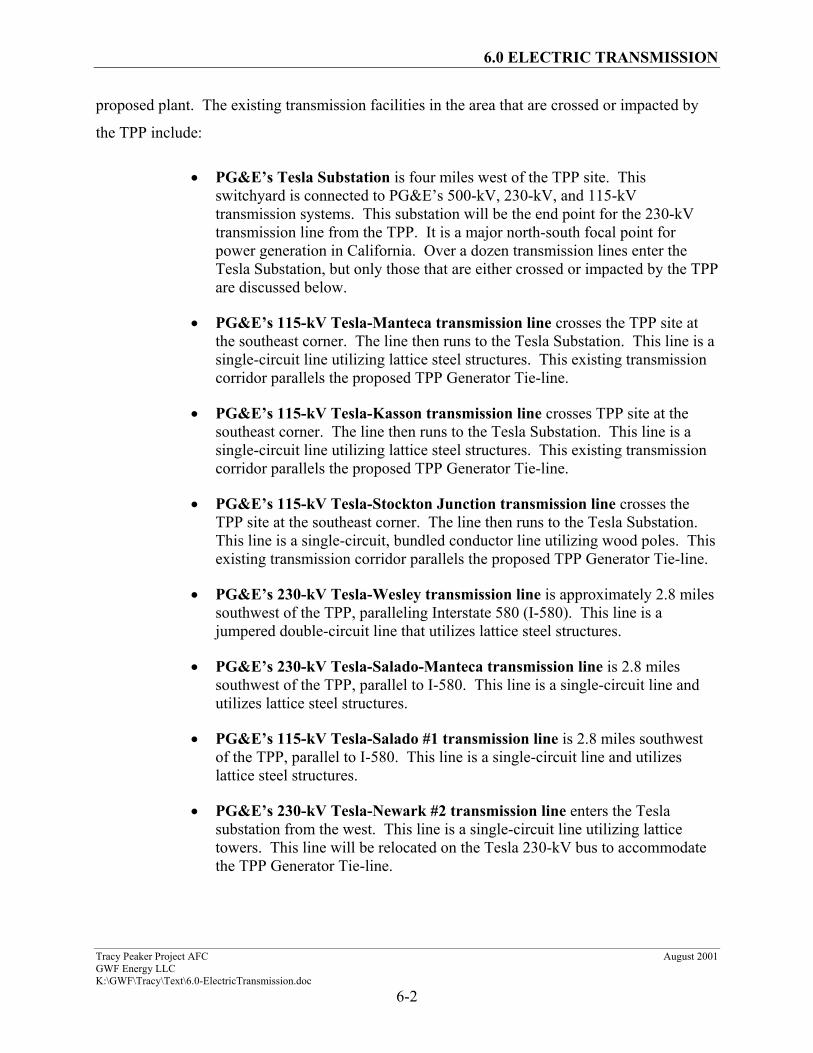
proposed plant. The existing transmission facilities in the area that are crossed or impacted by
the TPP include:
• PG&E’s Tesla Substation is four miles west of the TPP site. Thisswitchyard is connected to PG&E’s 500-kV, 230-kV, and 115-kVtransmission systems. This substation will be the end point for the 230-kVtransmission line from the TPP. It is a major north-south focal point forpower generation in California. Over a dozen transmission lines enter theTesla Substation, but only those that are either crossed or impacted by the TPPare discussed below.
• PG&E’s 115-kV Tesla-Manteca transmission line crosses the TPP site atthe southeast corner. The line then runs to the Tesla Substation. This line is asingle-circuit line utilizing lattice steel structures. This existing transmissioncorridor parallels the proposed TPP Generator Tie-line.
• PG&E’s 115-kV Tesla-Kasson transmission line crosses TPP site at thesoutheast corner. The line then runs to the Tesla Substation. This line is asingle-circuit line utilizing lattice steel structures. This existing transmissioncorridor parallels the proposed TPP Generator Tie-line.
• PG&E’s 115-kV Tesla-Stockton Junction transmission line crosses theTPP site at the southeast corner. The line then runs to the Tesla Substation.This line is a single-circuit, bundled conductor line utilizing wood poles. Thisexisting transmission corridor parallels the proposed TPP Generator Tie-line.
• PG&E’s 230-kV Tesla-Wesley transmission line is approximately 2.8 milessouthwest of the TPP, paralleling Interstate 580 (I-580). This line is ajumpered double-circuit line that utilizes lattice steel structures.
• PG&E’s 230-kV Tesla-Salado-Manteca transmission line is 2.8 milessouthwest of the TPP, parallel to I-580. This line is a single-circuit line andutilizes lattice steel structures.
• PG&E’s 115-kV Tesla-Salado #1 transmission line is 2.8 miles southwestof the TPP, parallel to I-580. This line is a single-circuit line and utilizeslattice steel structures.
• PG&E’s 230-kV Tesla-Newark #2 transmission line enters the Teslasubstation from the west. This line is a single-circuit line utilizing latticetowers. This line will be relocated on the Tesla 230-kV bus to accommodatethe TPP Generator Tie-line.
6.0 ELECTRIC TRANSMISSION
Tracy Peaker Project AFC August 2001GWF Energy LLCK:\GWF\Tracy\Text\6.0-ElectricTransmission.doc
6-3
6.1.2 Proposed Facilities
6.1.2.1 Tracy Peaker Project Switchyard
The 230-kV TPP switchyard will be located on the south side of the TPP site.
The switchyard will use a three-breaker radial bus configuration. Two of the three breaker
positions will be for the two 84.4-megawatt combustion turbine generators (one position for each
unit). The remaining breaker position will be used for the 230-kV connection to the TPP
Generator Tie-line.
The TPP switchyard will be designed in accordance with applicable industry
standards and will have the following ratings:
• Nominal voltage – 230 kV
• Basic impulse level – 900 kV
• Continuous current – 2,000 amperes
• Short-circuit current, included in PG&E’s System Impact/Facility Study
The switchyard will use a conventional outdoor-air-insulated rigid-bus design
supported on galvanized-steel structures. The switchyard will be fenced with a galvanized-steel,
chain-link fabric of a typical height. All nongalvanized structures and equipment will be painted
shades of ANSI gray. The control building will be a color similar to that of the adjacent TPP
power generation facility.
A ground mat will be installed to provide safe step-and-touch potentials for the
general public and switchyard operation and maintenance personnel. The grounding system will
be designed in accordance with American National Standards Institute/Institute of Electrical and
Electronics Engineers (ANSI/IEEE) 80.
The design of the switchyard’s lightning/shielding (static protection) will use the
electrogeometric or rolling-sphere method. The switchyard alternating current (AC) supply will
be derived from a redundant 480-volt AC feed from the TPP. The direct current (DC) supply for
the TPP control and protection systems of the station will be derived from a 125-volt DC station
6.0 ELECTRIC TRANSMISSION
Tracy Peaker Project AFC August 2001GWF Energy LLCK:\GWF\Tracy\Text\6.0-ElectricTransmission.doc
6-4
battery. The configuration of the TPP switchyard is shown on Figure 2-3. A one-line diagram
for the TPP switchyard is shown on Figure 6-2. Photo-simulations of the proposed switchyard
are shown in Section 8.11.
6.1.2.2 Tracy Peaker Project 230-kV Transmission Line
The proposed TPP Generator Tie-line will be a single-circuit line constructed on
galvanized tubular steel poles, typically 85 to 110 feet tall, though at certain crossings height
may be slightly taller. Angle and corner poles will be constructed of self-supporting, galvanized
tubular steel. Figure 6-1 shows the route of the proposed line. The route exits the TPP
switchyard to the southwest, crosses the Delta-Mendota Canal, and parallels the existing PG&E
transmission right-of-way. After approximately 2.8 miles, it turns northwest for 2.1 miles, until
it enters the Tesla Substation. The first 2.8 miles will be new pole and line construction, while
the last 2.1 miles will be reconductoring an existing line.
The proposed transmission line will require approximately 17 to 23 steel poles.
The ruling span is expected to be approximately 750 to 850 feet. The pole heights selected will
provide a minimum ground clearance of 30 feet at 60 degrees Fahrenheit (°F) and 28.5 feet at
130 °F, in accordance with the requirements of California Public Utilities Commission (CPUC)
General Order No. 95 (GO-95) (except where crossing railroad tracks, where the minimum
ground clearance will be 34 feet). The right-of-way width for the proposed transmission line will
generally be 75 feet.
The basic tangent structure for the proposed line will consist of a steel pole and
davit arms with polymer suspension insulators, as shown on Figure 6-3a. The basic dead-end
structure for the proposed line will consist of a steel pole and davit arms with polymer dead end
conductor insulators, as shown on Figure 6-3b. The tangent poles will use direct embedded
poles with concrete for its foundation, while the dead-end structures will be supported by anchor-
bolted foundations. Dead-end structures will be slightly taller and larger than tangent structures.
The proposed line route will cross over several existing transmission and
distribution lines. It is not anticipated that any customers will be affected by outages during the
line construction.
6.0 ELECTRIC TRANSMISSION
Tracy Peaker Project AFC August 2001GWF Energy LLCK:\GWF\Tracy\Text\6.0-ElectricTransmission.doc
6-5
The proposed line will use a single 795-kcmil aluminum-conductor steel-
reinforced (ACSR) “Condor” per phase. This conductor has a normal current rating (ampacity)
of 885 amperes kV markup. The normal conductor rating was determined from Alcoa’s T&D
Conductors, Overhead Underground handbook, based on a maximum conductor temperature rise
of 40 degrees Celsius (ºC) above a 40ºC ambient temperature, a 2 feet per second (fps)
crosswind, and an emissivity factor of 0.50 without sun. The conductor has an emergency rating
of 1,101 amperes. The emergency rating was determined from the Aluminum Electrical
Conductor Handbook, assuming a maximum conductor temperature rise of 60ºC over a 40ºC
ambient temperature, a 2-fps crosswind, and an emissivity factor of 0.50 without sun.
The proposed line will include one optical groundwire shield wire containing
approximately 24 optical fibers. The fiber-optic groundwire will be used to provide
communications paths for system protection, voice and data transmission, and shielding for
lightning protection.
The Tesla-Wesley reconductored line will utilize a single 954-kcmil aluminum-
clad steel-supported “Cardinal” per phase. This conductor has a normal current rating
(ampacity) of 1,865 amperes. The normal conductor rating was determined from Alcoa’s T&D
Conductors, Overhead Underground handbook, based on a maximum conductor temperature rise
of 40°C above a 40°C ambient temperature, a 2 fps crosswind, and an emissivity factor of 0.50
without sun. The reconductored line will include one fiber-optic cable.
6.1.2.3 Other
Typical industry design, operation, or maintenance practices will be required for
the proposed substation and transmission line facilities. Both substation sites and most
transmission structure locations will be accessible from existing dirt, gravel, or paved roads.
Short spur roads will be added and will not be graded unless necessary. An access plan will be
prepared for construction to designate acceptable construction access routes. Construction
access routes will be flagged in the field as required.
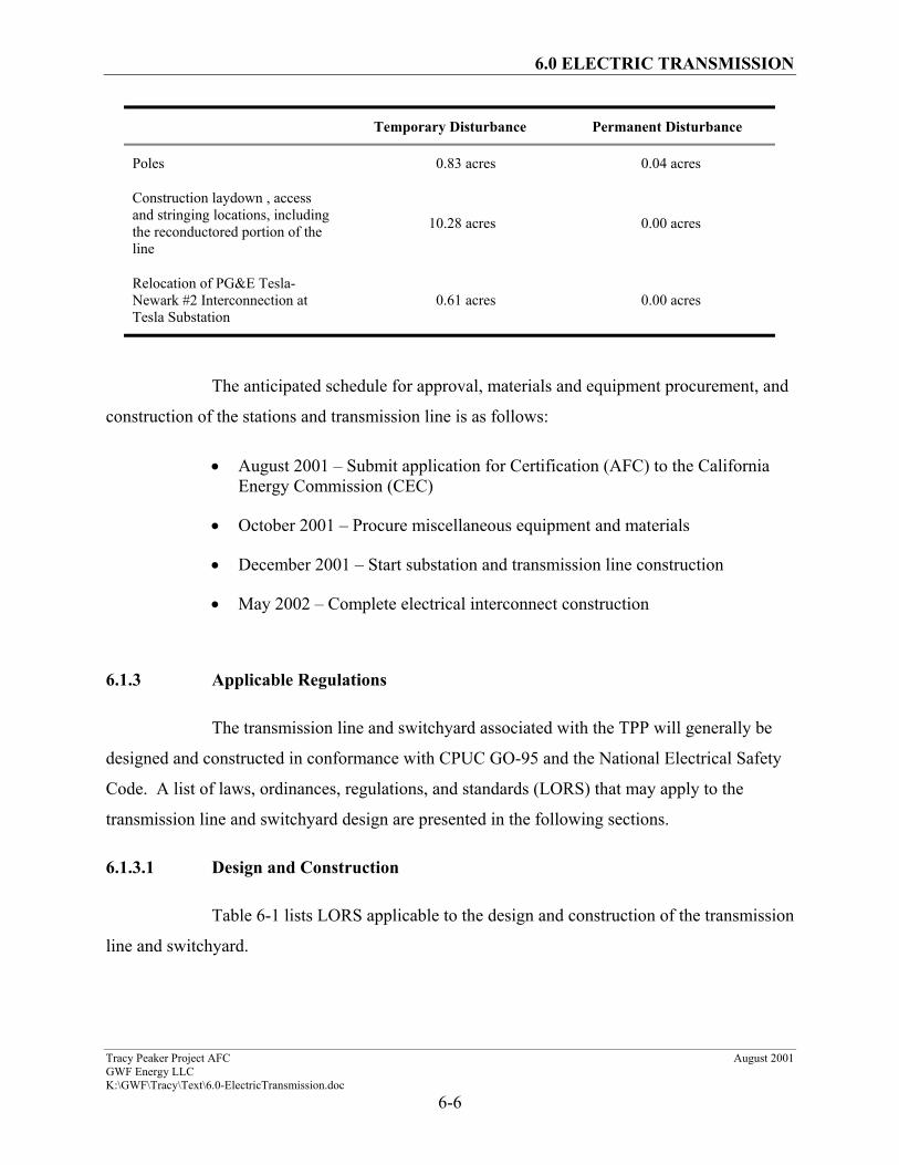
An estimate of temporary and permanent disturbance associated with construction
of the TPP transmission line is provided below:
6.0 ELECTRIC TRANSMISSION
Tracy Peaker Project AFC August 2001GWF Energy LLCK:\GWF\Tracy\Text\6.0-ElectricTransmission.doc
6-6
Temporary Disturbance Permanent Disturbance
Poles 0.83 acres 0.04 acres
Construction laydown , accessand stringing locations, includingthe reconductored portion of theline
10.28 acres 0.00 acres
Relocation of PG&E Tesla-Newark #2 Interconnection atTesla Substation
0.61 acres 0.00 acres
The anticipated schedule for approval, materials and equipment procurement, and
construction of the stations and transmission line is as follows:
• August 2001 – Submit application for Certification (AFC) to the CaliforniaEnergy Commission (CEC)
• October 2001 – Procure miscellaneous equipment and materials
• December 2001 – Start substation and transmission line construction
• May 2002 – Complete electrical interconnect construction
6.1.3 Applicable Regulations
The transmission line and switchyard associated with the TPP will generally be
designed and constructed in conformance with CPUC GO-95 and the National Electrical Safety
Code. A list of laws, ordinances, regulations, and standards (LORS) that may apply to the
transmission line and switchyard design are presented in the following sections.
6.1.3.1 Design and Construction
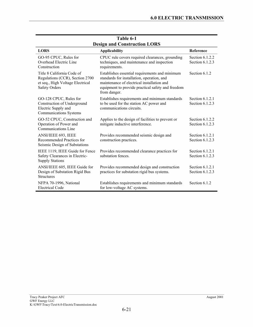
Table 6-1 lists LORS applicable to the design and construction of the transmission
line and switchyard.
6.0 ELECTRIC TRANSMISSION
Tracy Peaker Project AFC August 2001GWF Energy LLCK:\GWF\Tracy\Text\6.0-ElectricTransmission.doc
6-7
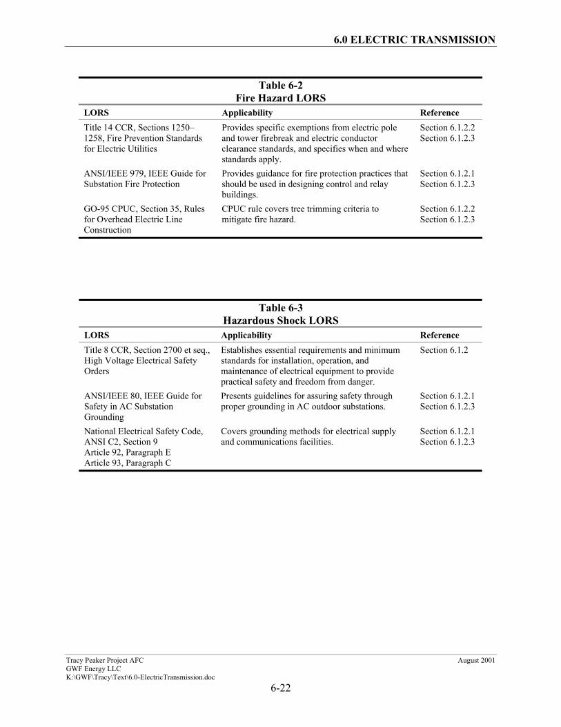
6.1.3.2 Fire Hazard
Table 6-2 lists the LORS that govern fire hazard protection for the TPP.
6.1.3.3 Hazardous Shock
Table 6-3 lists the LORS regarding hazardous shock protection for the TPP.
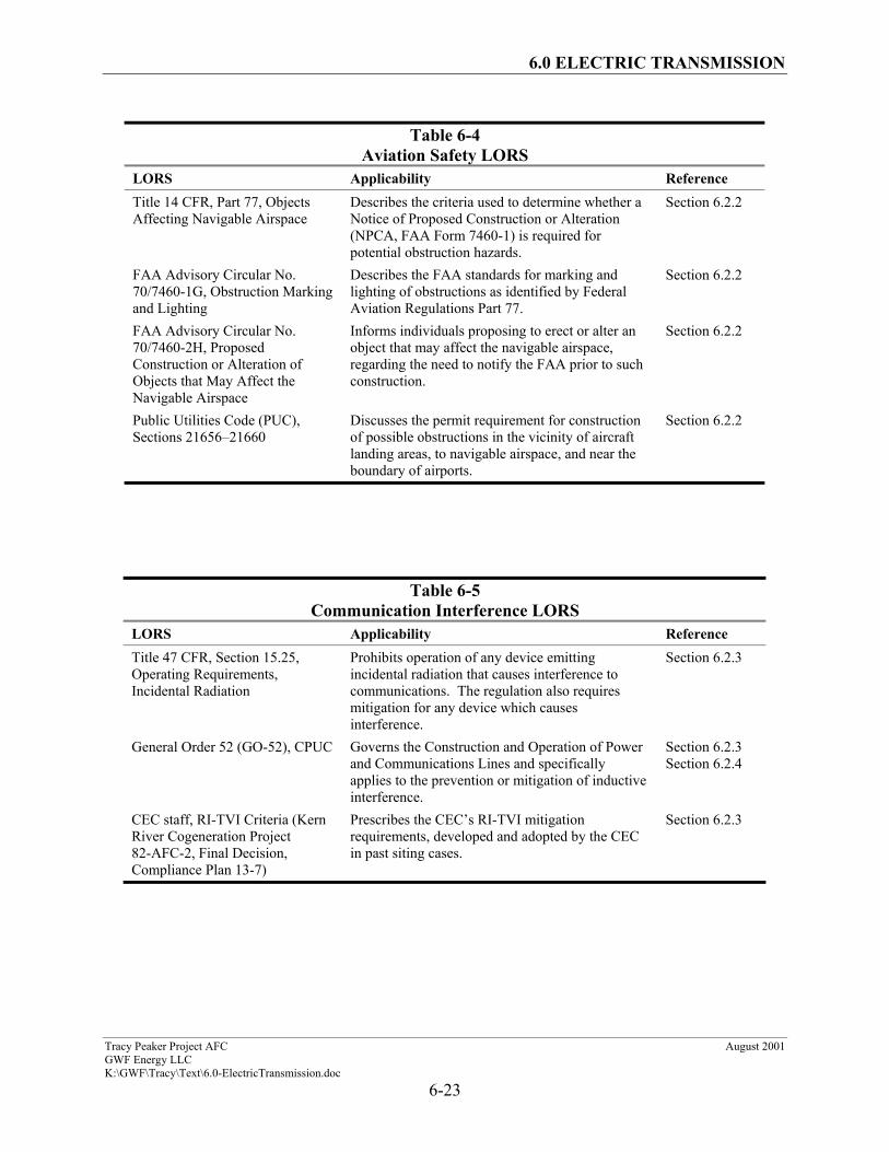
6.1.3.4 Aviation Safety
Table 6-4 lists the applicable aviation safety LORS.
6.1.3.5 Communication Interference
Table 6-5 lists the applicable LORS regarding communications interference.
6.2 Transmission Line Electrical Effects
6.2.1 Project Characteristics
To integrate the TPP output into the PG&E 230-kV transmission system, GWF
Energy LLC intends to construct a five-mile, 230-kV transmission line between the TPP and
PG&E’s 230-kV Tesla Substation. The first 2.8 miles will be new pole and line construction,
while the remaining 2.1 miles will use existing towers and one of the two existing unjumpered
Tesla-Wesley circuits.
The following design criteria and assumptions were used to complete the initial
design of the project’s proposed or alternate transmission line and calculate its electromagnetic
field (EMF), audible noise, and radio/television interference effects.
6.2.1.1 Assumptions
The nominal transmission voltage will be 230 kV. For these calculations, the
transmission line loading will be a nominal 169 MW. The line will be a single-circuit line
composed of one 795-kcmil ACSR conductor per phase. The unjumpered line that will be
upgraded by PG&E as part of the project to accommodate existing power flow to Tesla will
6.0 ELECTRIC TRANSMISSION
Tracy Peaker Project AFC August 2001GWF Energy LLCK:\GWF\Tracy\Text\6.0-ElectricTransmission.doc
6-8
consist of one 954-kcmil ACSS conductor per phase. The tower just southeast of the PG&E
Tesla-Wesley line has two 230-kV lines, consisting of bundled cable, with two 795-kcmil ACSR
per phase. All other lines are assumed single-conductor per phase, made of 795-kcmil ACSR.
All lines are assumed at maximum rated loading, with the exception of the 230-kV TPP
Generator Tie-line, which will be at 425 amperes. Profile views of the transmission line
corridors are provided in Appendix A.
The phase currents will be balanced (equal). The power factor used in the
calculations will be 0.98 (leading or lagging). Continuous plant operation will not occur at this
power factor, and variations in the actual power factor can be expected. This power factor
represents a typical value for this area.
For the purposes of these calculations and to be conservative, the EMF, radio
interference (RI), television interference (TVI), and audible noise calculations were performed at
an assumed minimum conductor height above ground of 26 feet (mid-span). However, from a
design perspective, the conductors will be a minimum of 30 feet above the ground (34 feet above
railroad tracks).
The calculations were performed using the Bonneville Power Administration’s
(BPA) Corona and Field Effects Program.
6.2.1.2 Conductor Analysis
The selection of a phase conductor size and type for a new transmission line
typically considers a number of factors. These factors include the following:
Thermal Capacity. The conductor size/type selected must have a thermal
capacity greater than the initial and future capacity requirements of the project.
Economics. Economic evaluations typically consider the effects on conductor,
structure, and foundation costs of various conductor sizes/types and bundle configurations
(conductor diameters, sags, and tensions). The present worth of conductor losses is also
typically considered.
6.0 ELECTRIC TRANSMISSION
Tracy Peaker Project AFC August 2001GWF Energy LLCK:\GWF\Tracy\Text\6.0-ElectricTransmission.doc
6-9
Environmental. Electric and magnetic field strengths are largely dependent on
the maximum line operating voltage, phase conductor currents, and the spatial arrangement
(configuration) of the phase conductors, not the conductor size/type.
Standardization. Industry standard/typical conductor sizes/types and bundle
configurations are given preference because of operation and maintenance, and in-service
reliability considerations.
Minimum Size. A minimum allowable conductor size of 795 kcmil was selected
for this project. This size selection was based on a combination of RI/TVI, corona, mechanical
sag, and strength considerations and is applicable to nonbundled phase conductors only.
The same conductor size has been maintained for the proposed and the alternate
transmission line configurations. For these calculations, the maximum anticipated loading on the
proposed single-circuit transmission line is 191 MW (195 millivolt-amperes at 0.98 power
factor). This loading will result in a maximum current in each phase of 489 amperes at 230 kV.
6.2.2 Aviation Safety
There is no major commercial aviation center in the general vicinity of the
project. The Stockton airport is over 20 miles northeast of the TPP area. A smaller local airport
in Tracy, the Tracy Municipal Airport, is within two miles of the project transmission line.
In accordance with Title 14, Part 77 of the Code of Federal Regulations (CFR), a
Notice of Construction or Alteration must be filed with the Federal Aviation Administration
(FAA) if there is any structure rising 200 feet (500 feet in uncongested areas) above the average
ground level in the vicinity of the construction site. A notice is also required if any structure
protrudes above an imaginary surface extending from the end of the nearest runway at a slope of
50:1 for 10,000 feet, if the longest runway length at the airport is 3,200 feet or less; or a slope of
100:1 for 20,000 feet, if the longest runway at the airport is longer than 3,200 feet.
6.0 ELECTRIC TRANSMISSION
Tracy Peaker Project AFC August 2001GWF Energy LLCK:\GWF\Tracy\Text\6.0-ElectricTransmission.doc
6-10
The closest runway is less than two miles away, but the transmission line will not
cut the extended imaginary surface of the airport runway. Therefore, a FAA Notice of
Construction is not required for the transmission line.
Some local crop dusting does occur in the project area. The TPP Generator Tie-
line will follow existing transmission corridors and will not introduce a significant obstacle for
crop dusting activities.
6.2.3 Audible Noise and Radio/TV Interference
Audible noise is defined as any unwanted sound from a man-made source such as
a transmission line, a transformer, an airport, vehicular traffic, etc. Audible noise is
superimposed on the background or ambient noise that existed prior to the introduction of the
audible noise source.
When an electric transmission line is energized, an electric field is generated in
the air around the conductors. This electric field may cause corona (the breakdown of the air in
the vicinity of the transmission line phase conductors). When the intensity of the electric field at
the conductor surface exceeds the breakdown strength of the surrounding air, a corona discharge
occurs at the conductor surface. This corona discharge produces energy, which can result in
audible noise and/or radio interference and television interference. The corona effects from the
line were calculated using the BPA CFE Program.
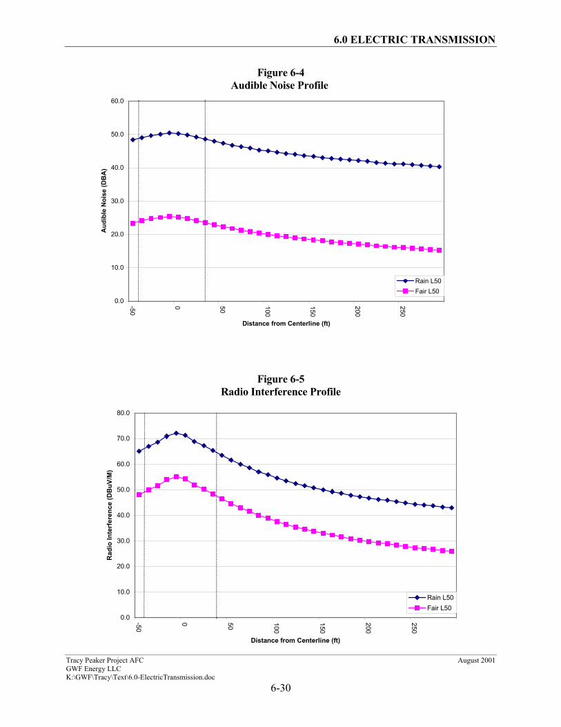
Corona-generated audible noise can be characterized as a hissing, crackling
sound, which, under certain conditions, can be heard. The noise levels generated by the line are
very low, and most of the time the audible noise will not be detectable, except in an area directly
beneath the line on a quiet day. The audible noise calculation results for the proposed line are
shown on Figure 6-4.
Corona on transmission line conductors can also generate electromagnetic noise
in the frequency bands used for radio and television signals. This phenomenon is generally
referred to as RI and TVI. These terms are commonly applied to any disturbance within the
radio frequency band. RI and TVI consist of two distinct types: gap-type noise and noise due to
6.0 ELECTRIC TRANSMISSION
Tracy Peaker Project AFC August 2001GWF Energy LLCK:\GWF\Tracy\Text\6.0-ElectricTransmission.doc
6-11
corona. Gap-type noise is the result of sparking or arcing between two pieces of hardware. This
arcing occurs when hardware is loose (not tight-fitting), or at sharp burrs or edges on the
hardware. This type of noise occurs at discrete points along the line and is often associated with
undermaintained lines. Such interference can be easily identified and corrected with proper
maintenance. The second type of noise is caused by corona on the conductors. This corona
noise emanates from the entire length of conductor and is typically referred to as RI and TVI.
Corona-related interference with radio and television reception is typically
associated with transmission line voltages of 345 kV or greater, although it may occur at lower
voltages. It is a direct function of the strength of the received radio/television signal and the
level of the noise present. The signal to noise ratio (S/N) is defined as the ratio of the average
signal power to the average noise power. The higher the S/N ratio, the better the reception
quality. A high S/N ratio indicates a high signal level and a low noise level. Consider the
analogy of a person talking in a room with low background noise and a person talking in a room
with high background noise. If the person’s voice (signal level) remains constant, the person
will be heard much more easily in a room with low background noise than the person in a room
with high background noise. This concept also applies to radio and television signals in the
presence of background noise.
It is difficult to determine whether a particular level of RI or TVI will cause
unacceptable radio or television reception. Studies have been conducted, however, to determine
acceptable signal to noise ratios. For radio reception, a S/N ratio above 20 is generally
considered to provide acceptable reception. For television reception, an S/N ratio of 30 to 40
typically provides acceptable reception. It is anticipated that for receivers proximate to the
proposed line right-of-way, there will be little, if any, degradation of radio or Television
reception. The exception, if there is one, will be for very remote, poorly received stations. In
addition, RI typically interferes with amplitude modulated (AM) stations only. Frequency
modulated (FM) stations are generally immune to RI because of the inherent characteristics of
the modulation scheme. Therefore, the probability for RI complaints is reduced, as a major band
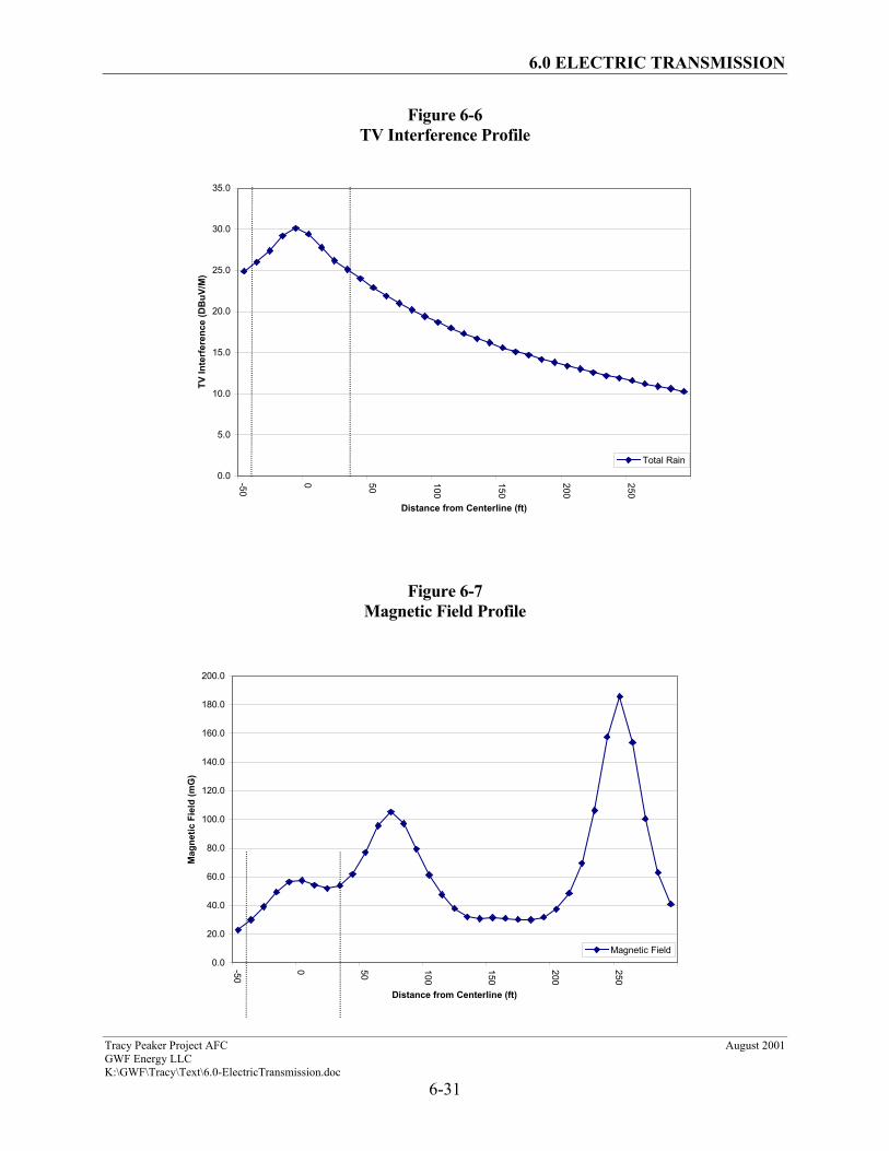
of the radio broadcast spectrum is generally unaffected by the phenomenon. The calculated RI
and TVI for the proposed transmission line are shown on Figures 6-5 and 6-6, respectively.
6.0 ELECTRIC TRANSMISSION
Tracy Peaker Project AFC August 2001GWF Energy LLCK:\GWF\Tracy\Text\6.0-ElectricTransmission.doc
6-12
These levels of interference are not expected to be noticeable, except for remote stations. The
TVI at the edge of the right-of-way will be noticeable only for weak (remote) stations.
The proposed line will be maintained as part of a regular maintenance program.
Therefore, it is unlikely any gap-type noise will result. If any is reported or discovered, it will be
quickly mitigated. In addition, it is anticipated that few if any RI/TVI complaints will occur,
because of the low magnitude of calculated corona noise. If complaints do occur, they will be
addressed, investigated, and mitigated if needed, on a case-by-case basis.
6.2.4 Electric and Magnetic Fields
Electricity is a phenomenon resulting from the existence and interaction of
charges. When a charge is stationary or static, it produces forces on objects in regions where it is
present. When a charge is in motion, it produces magnetic effects. Whenever electricity is used
or transmitted, electric and magnetic fields are created. Transmission lines, distribution lines,
house wiring, and appliances produce electric fields in their vicinity due to the electric charges
associated with the appliances/conductors. Electric field strengths are typically expressed in
units of volts per meter (V/m) or kilovolts (thousands of volts) per meter (kV/m).
Electric charges in motion (currents) produce magnetic fields. The strength of a
magnetic field is proportional to the current through the conductor (circuit) producing the field.
Magnetic fields can be characterized by the force they exert on a moving charge or on an electric
current. Electric currents are sources of magnetic fields. Magnetic field strengths are measured
in milligauss (mG).
An example of electric and magnetic fields in a home is a lamp plugged into an
electrical outlet. If the lamp is turned off, an electric field exists in the vicinity of the cord of the
lamp because of the voltage on the cord. When the lamp is turned on, current flows through the
cord and a magnetic field also exists around the cord because of the current flow.
The strength of an electric field depends on the potential (voltage) of the source of
the field, and distance from that source to the point of measurement of the field strength.
Electric fields decrease rapidly as the distance (r) from the source increases. If an energized
6.0 ELECTRIC TRANSMISSION
Tracy Peaker Project AFC August 2001GWF Energy LLCK:\GWF\Tracy\Text\6.0-ElectricTransmission.doc
6-13
conductor (source) is placed inside a grounded conducting enclosure, the electric field outside
the enclosure will approach zero (limited by ambient electric field level), and the source is said
to be shielded.
Transmission-line-related magnetic fields decrease at a rate of 1/r2 if currents are
balanced and conductors are closely spaced. Magnetic fields associated with unbalanced phase
currents decrease at a rate inversely proportional to the distance from the source (conductor), at a
rate of 1/r. Transmission lines typically are operated with balanced phase currents.
The electric field created by a high-voltage transmission line extends from the
energized conductors to other nearby conducting objects such as the ground, structures,
vegetation, buildings, vehicles, and people. The strength of the vertical component of the
electric field at a height of 1 meter (3.28 feet) is frequently used to characterize electric fields
under transmission lines.
The transmission line parameters that have the greatest effect on electric and
magnetic field levels in the vicinity of a transmission line are maximum operating voltage, line
current, conductor height, and electrical phasing. The maximum ground level electric and
magnetic fields typically occur near the centerline of a line and at mid-span where the conductors
are closest to the ground. For purposes of these estimates, the minimum mid-span conductor
height is assumed to be 26 feet.
The electric and magnetic fields from the proposed transmission line were
calculated using the BPA Corona and Field Effects Program. The strengths of the electric and
magnetic fields were calculated for a sensor height of 1 meter above ground. Calculations were
performed based on the minimum 26-foot ground clearance and extend to 200 feet on each side
of the centerline. The calculated magnetic fields produced by the proposed line operating at peak
loading conditions are shown on Figure 6-7.
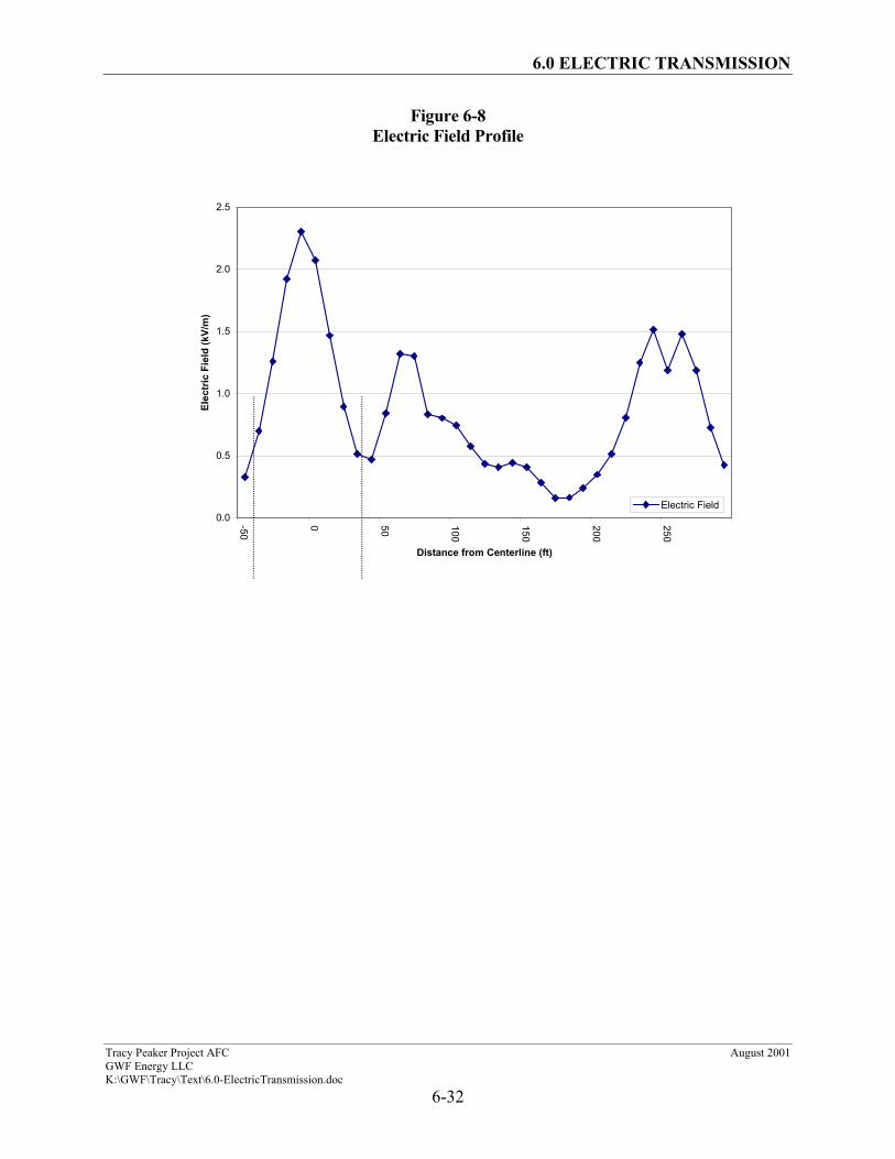
The first section of transmission line from the TPP plant, the 2.8 miles of new
construction adjacent to an existing PG&E right-of-way, affects the electromagnetic field and the
electric field (see Figures 6-7 and 6-8 and the “Cut 1” data set attached in Appendix A). The
second section, the 2.1 miles of reconductored PG&E transmission line that connects to the Tesla
6.0 ELECTRIC TRANSMISSION
Tracy Peaker Project AFC August 2001GWF Energy LLCK:\GWF\Tracy\Text\6.0-ElectricTransmission.doc
6-14
Substation, will be located between two existing lines within a PG&E right-of-way. This section
will not significantly affect the electromagnetic field and the electric field at the edge of the
right-of-way (as shown in the “Cut 2” data set attached in Appendix A).
Note that for maximum current flow, the magnetic field at the outside edge of the
transmission line corridor in the first (2.8-mile) section will be approximately 41.2 mG. The
manectic field levels are directly proportional to the current flowing through the transmission
line. When current flow is increased or reduced so does the magnetic field level.
The proposed route of the TPP Generator Tie-line is through sparsely populated
area of San Joaquin County. The closest house to the proposed route is approximately 180 feet
away. At this distance, the contribution of the magnetic field of the transmission line in the first
(2.8-mile) section to the overall magnetic field level will be 30.04 mG. The electric field levels
produced by the proposed transmission line are shown on Figure 6-8. Note that at the outside
edge of the transmission line corridor, the electric field level will be approximately 0.42 kV/m.
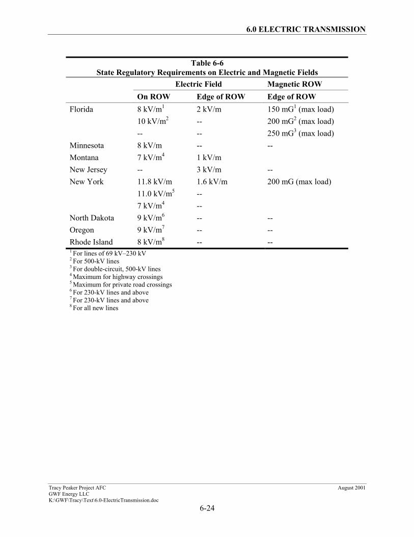
Given the concerns about human exposure to electric and magnetic fields and
possible adverse health affects, several states have adopted standards limiting electric and
magnetic field levels within or at the edge of transmission line rights-of-way (see Table 6-6).
California is not one of these states. However, while California does not have regulatory
requirements for transmission line magnetic fields, the calculated magnetic fields for the
proposed transmission line (refer to Figures 6-7 and 6-8) are much lower than the requirements
for those states with existing limitations.
California does not regulate the level of transmission line electric fields.
However, calculated values for the proposed line (refer to Figure 6-8) are also substantially
below the levels established by those states that do have limits.
6.2.4.1 Transmission Line Electromagnetic Field Reduction
While the State of California does not limit electric and magnetic field levels, the
CPUC mandates EMF reduction as a practicable design criterion for new and upgraded electrical
facilities. From this mandate, the regulated electric utilities, including PG&E, have developed
6.0 ELECTRIC TRANSMISSION
Tracy Peaker Project AFC August 2001GWF Energy LLCK:\GWF\Tracy\Text\6.0-ElectricTransmission.doc
6-15
their own design guidelines to reduce EMF at each new facility. The CEC requires independent
power producers to follow the guidelines that have already been established by the local electric
utility or transmission-system owner.
In keeping with the goal of EMF reduction, the TPP interconnection will be
generally designed and constructed using the principles outlined in the PG&E publication,
Transmission Line EMF Guidelines. These guidelines incorporate the directives of the CPUC by
developing design procedures that comply with Decision 93-11-013 and GO-95, 128, and 131-D.
In other words, when the towers, conductors, and rights-of-way are designed and routed
according to the PG&E guidelines, the transmission line is consistent with the CPUC mandate.
From the PG&E guidelines, the primary techniques for reducing EMF anywhere
along the line are the following:
• Increase the distance from the line conductors
• Reduce the spacing between the line conductors
• Minimize the current on the line
• Optimize the configuration of the phases (A, B, C)
To increase the distance from the line conductors, the line will be routed along an
existing utility corridor, thereby avoiding proximity to residential and public-use areas. The
nearest residence is approximately 250 feet away. Additionally, along the route of the overhead
line, the adjacent land is a mix of industrial, agricultural, and vacant land.
Reducing the spacing between the conductors can reduce magnetic fields. Also,
for the double-circuit case, the circuits on one side will be reverse-phased from the circuits on
the other side to further reduce resulting magnetic fields.
While the EMF levels have been calculated for the TPP Generator Tie-line as
designed, the CEC requires actual measurement of EMF for comparison of “before”
(background) with “after” (transmission line and background together) EMF levels. These
verification measurements will be made consistent with Institute of Electrical and Electronics
6.0 ELECTRIC TRANSMISSION
Tracy Peaker Project AFC August 2001GWF Energy LLCK:\GWF\Tracy\Text\6.0-ElectricTransmission.doc
6-16
Engineers guidelines and will provide sampled readings of edge of right-of-way EMF.
Additional measurements will be made upon request for areas of particular concern.
6.2.4.2 Conclusion on Electromagnetic Fields
Electromagnetic field reduction will be an integral consideration during the design
and routing of the interconnection between the TPP and the offsite switchyard. Since the PG&E
Transmission Line EMF Guidelines embody the CPUC directives for EMF reduction, the
guidelines are the primary criteria for EMF considerations in this project.
The route of the proposed transmission line is not near any areas of public
concern, including schools and day care centers. Mitigation measures, such as locating the line
away from sensitive facilities or increasing the aboveground height of the conductor when a
sensitive facility is close to the edge of the right-of-way, will not be required.
6.2.5 Induced Current and Voltages
A conducting object, such as a vehicle or person, in an electric field will
experience induced voltages and currents. The magnitude of the induced current will depend
upon the electric field strength, the size and shape of the object, and object-to-ground resistance.
The measured induced current for a person in a 1-kV/m electric field is 0.016 milliamps (mA);
for a large school bus, 0.41 mA; and for a large trailer truck, 0.63 mA.
When a conducting object in an electric field is isolated from ground, and a
grounded person touches the object, a perceptible current or shock may occur. The magnitude of
the current depends upon the field strength, the size (or length for fences, pipelines, and railroad
tracks) of the object, and the grounding resistance of the object and person. Shocks are classified
as below perception, above perception, secondary, and primary. The mean perception level is
1.0 mA for a 180-pound man and 0.7 mA for a 120-pound woman. Secondary shocks cause no
direct physiological harm but may annoy a person and cause involuntary muscle contraction.
The lower average secondary-shock level for an average-sized man is about 2 mA. Primary
shocks can be harmful; their lower level is described as the current at which 99.5 percent of
6.0 ELECTRIC TRANSMISSION
Tracy Peaker Project AFC August 2001GWF Energy LLCK:\GWF\Tracy\Text\6.0-ElectricTransmission.doc
6-17
subjects can still voluntarily “let go” of the shocking electrode. For the 180-pound man this is
9 mA, for the 120-pound woman, 6 mA, and for children, 5 mA.
The National Electric Safety Code specifies 5 mA as the maximum allowable
short-circuit current to ground from vehicles, trucks, and equipment near transmission lines.
The mitigation for hazardous and nuisance shocks is to ensure that metallic
objects on or near the right-of-way are grounded, and that sufficient clearances are provided at
roadways and parking lots to keep electric-field-induced voltages at these locations sufficiently
low to prevent vehicle short-circuit currents resulting from vehicle contact by persons below
5 mA.
Magnetic fields can also induce voltages and currents in conducting objects.
Typically, this requires a long metallic object such as a fence, pipeline, or railroad that is
grounded at only one location. A person who touches the object, at a location remote from the
grounded point, will experience a shock similar to that described above for an ungrounded
object. Installing multiple grounds on fences or pipelines parallel to the transmission line can
mitigate this problem.
The proposed 230-kV TPP Generator Tie-line will be constructed in conformance
with GO-95 and Title 8 CCR, Section 2700 requirements. Therefore, hazardous shocks are
unlikely to occur as a result of the TPP construction or operation.
6.2.6 Nuisance Shocks
Normal grounding practices effectively mitigate the possibility of nuisance shocks
resulting from induced currents from stationary objects near the line, such as fences and
buildings. Since the electric field extends beyond the right-of-way, grounding requirements
extend beyond the right-of-way for very large metal objects or very long fences. Electric fences
require a special grounding technique because they can operate only if they are insulated.
Application of the grounding policy during and after construction will effectively mitigate the
potential for shocks from stationary objects near the proposed line.
6.0 ELECTRIC TRANSMISSION
Tracy Peaker Project AFC August 2001GWF Energy LLCK:\GWF\Tracy\Text\6.0-ElectricTransmission.doc
6-18
6.2.7 Fire Hazards
The transmission line and switchyards will be constructed in conformance with
CPUC GO-95 and National Electric Safety Code standards. Title 14 CCR, Section 1250, Article
4 (from CPUC GO-95) establishes fire prevention standards for electric utilities. The TPP will
comply with these standards.
6.2.8 Cumulative Impacts
The proposed transmission line will operate proximate to existing transmission
lines along the right-of-way. Interaction with the electric and magnetic fields of other existing
lines will depend on the phase arrangements and relative positions of the conductors of the new
line compared to the existing lines. An evaluation of these interactions will require detailed
construction data on the existing transmission lines that are not currently available. Corona noise
for the proposed line is projected to be small and is not expected to significantly increase the
ambient noise near the existing lines.
6.3 Transmission System Evaluation
6.3.1 Description of Transmission Alternatives
Several interconnection alternatives were reviewed to determine options for
integrating the nominal 169-MW plant output into the California transmission system grid. The
alternative interconnections are described in Section 5.0 (Alternatives). Refer to Figure 6-1 for
details of the transmission line routings and switchyard site locations for these alternatives. In
the selection of the interconnection points shown, consideration was given to the following:
• Potential environmental impacts of the line between the TPP and the point ofinterconnection
• The ability to obtain the right-of-way required for the line
• Potential engineering constraints
6.0 ELECTRIC TRANSMISSION
Tracy Peaker Project AFC August 2001GWF Energy LLCK:\GWF\Tracy\Text\6.0-ElectricTransmission.doc
6-19
6.3.2 Applicant’s Interconnection Study
GWF commissioned Navigant to perform a load flow and transient system impact
analysis on PG&E’s behalf. In addition, PG&E completed a fault current study for the project.
The results of these analyses are included in Appendix A. No significant impacts were identified
that would require additional facilities or other mitigation measures.
6.3.3 PG&E System Impact/Facility Study
GWF Energy LLC requested that PG&E prepare a System Impact/Facility Study
for the electrical interconnection of the proposed TPP. The draft study will be circulated to the
Independent System Operator (ISO) for review in September 2001. The final (ISO-approved)
study will be available in October 2001. The study will evaluate the potential impacts of adding
169 MW (at 0.85 power factor) of generation to the PG&E system. The scope of work for the
study is included in Appendix A.
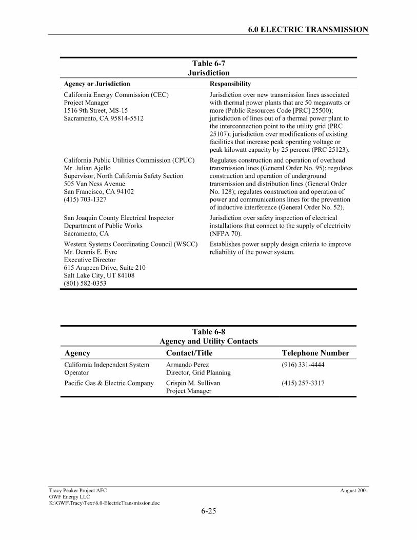
6.4 Jurisdiction
Table 6-7 identifies agencies with jurisdiction to issue permits and approvals,
and/or enforce laws and regulations.
6.5 Agency Contacts
Local contacts for the TPP transmission line and the switchyard are shown in
Table 6-8.
6.0 ELECTRIC TRANSMISSION
Tracy Peaker Project AFC August 2001GWF Energy LLCK:\GWF\Tracy\Text\6.0-ElectricTransmission.doc
6-20
TABLES
6.0 ELECTRIC TRANSMISSION
Tracy Peaker Project AFC August 2001GWF Energy LLCK:\GWF\Tracy\Text\6.0-ElectricTransmission.doc
6-21
Table 6-1Design and Construction LORS
LORS Applicability ReferenceGO-95 CPUC, Rules forOverhead Electric LineConstruction
CPUC rule covers required clearances, groundingtechniques, and maintenance and inspectionrequirements.
Section 6.1.2.2Section 6.1.2.3
Title 8 California Code ofRegulations (CCR), Section 2700et seq., High Voltage ElectricalSafety Orders
Establishes essential requirements and minimumstandards for installation, operation, andmaintenance of electrical installation andequipment to provide practical safety and freedomfrom danger.
Section 6.1.2
GO-128 CPUC, Rules forConstruction of UndergroundElectric Supply andCommunications Systems
Establishes requirements and minimum standardsto be used for the station AC power andcommunications circuits.
Section 6.1.2.1Section 6.1.2.3
GO-52 CPUC, Construction andOperation of Power andCommunications Line
Applies to the design of facilities to prevent ormitigate inductive interference.
Section 6.1.2.2Section 6.1.2.3
ANSI/IEEE 693, IEEERecommended Practices forSeismic Design of Substations
Provides recommended seismic design andconstruction practices.
Section 6.1.2.1Section 6.1.2.3
IEEE 1119, IEEE Guide for FenceSafety Clearances in Electric-Supply Stations
Provides recommended clearance practices forsubstation fences.
Section 6.1.2.1Section 6.1.2.3
ANSI/IEEE 605, IEEE Guide forDesign of Substation Rigid BusStructures
Provides recommended design and constructionpractices for substation rigid bus systems.
Section 6.1.2.1Section 6.1.2.3
NFPA 70-1996, NationalElectrical Code
Establishes requirements and minimum standardsfor low-voltage AC systems.
Section 6.1.2
6.0 ELECTRIC TRANSMISSION
Tracy Peaker Project AFC August 2001GWF Energy LLCK:\GWF\Tracy\Text\6.0-ElectricTransmission.doc
6-22
Table 6-2Fire Hazard LORS
LORS Applicability ReferenceTitle 14 CCR, Sections 1250–1258, Fire Prevention Standardsfor Electric Utilities
Provides specific exemptions from electric poleand tower firebreak and electric conductorclearance standards, and specifies when and wherestandards apply.
Section 6.1.2.2Section 6.1.2.3
ANSI/IEEE 979, IEEE Guide forSubstation Fire Protection
Provides guidance for fire protection practices thatshould be used in designing control and relaybuildings.
Section 6.1.2.1Section 6.1.2.3
GO-95 CPUC, Section 35, Rulesfor Overhead Electric LineConstruction
CPUC rule covers tree trimming criteria tomitigate fire hazard.
Section 6.1.2.2Section 6.1.2.3
Table 6-3Hazardous Shock LORS
LORS Applicability ReferenceTitle 8 CCR, Section 2700 et seq.,High Voltage Electrical SafetyOrders
Establishes essential requirements and minimumstandards for installation, operation, andmaintenance of electrical equipment to providepractical safety and freedom from danger.
Section 6.1.2
ANSI/IEEE 80, IEEE Guide forSafety in AC SubstationGrounding
Presents guidelines for assuring safety throughproper grounding in AC outdoor substations.
Section 6.1.2.1Section 6.1.2.3
National Electrical Safety Code,ANSI C2, Section 9Article 92, Paragraph EArticle 93, Paragraph C
Covers grounding methods for electrical supplyand communications facilities.
Section 6.1.2.1Section 6.1.2.3
6.0 ELECTRIC TRANSMISSION
Tracy Peaker Project AFC August 2001GWF Energy LLCK:\GWF\Tracy\Text\6.0-ElectricTransmission.doc
6-23
Table 6-4Aviation Safety LORS
LORS Applicability ReferenceTitle 14 CFR, Part 77, ObjectsAffecting Navigable Airspace
Describes the criteria used to determine whether aNotice of Proposed Construction or Alteration(NPCA, FAA Form 7460-1) is required forpotential obstruction hazards.
Section 6.2.2
FAA Advisory Circular No.70/7460-1G, Obstruction Markingand Lighting
Describes the FAA standards for marking andlighting of obstructions as identified by FederalAviation Regulations Part 77.
Section 6.2.2
FAA Advisory Circular No.70/7460-2H, ProposedConstruction or Alteration ofObjects that May Affect theNavigable Airspace
Informs individuals proposing to erect or alter anobject that may affect the navigable airspace,regarding the need to notify the FAA prior to suchconstruction.
Section 6.2.2
Public Utilities Code (PUC),Sections 21656–21660
Discusses the permit requirement for constructionof possible obstructions in the vicinity of aircraftlanding areas, to navigable airspace, and near theboundary of airports.
Section 6.2.2
Table 6-5Communication Interference LORS
LORS Applicability ReferenceTitle 47 CFR, Section 15.25,Operating Requirements,Incidental Radiation
Prohibits operation of any device emittingincidental radiation that causes interference tocommunications. The regulation also requiresmitigation for any device which causesinterference.
Section 6.2.3
General Order 52 (GO-52), CPUC Governs the Construction and Operation of Powerand Communications Lines and specificallyapplies to the prevention or mitigation of inductiveinterference.
Section 6.2.3Section 6.2.4
CEC staff, RI-TVI Criteria (KernRiver Cogeneration Project82-AFC-2, Final Decision,Compliance Plan 13-7)
Prescribes the CEC’s RI-TVI mitigationrequirements, developed and adopted by the CECin past siting cases.
Section 6.2.3
6.0 ELECTRIC TRANSMISSION
Tracy Peaker Project AFC August 2001GWF Energy LLCK:\GWF\Tracy\Text\6.0-ElectricTransmission.doc
6-24
Table 6-6State Regulatory Requirements on Electric and Magnetic Fields
Electric Field Magnetic ROWOn ROW Edge of ROW Edge of ROW
Florida 8 kV/m1 2 kV/m 150 mG1 (max load)10 kV/m2 -- 200 mG2 (max load)-- -- 250 mG3 (max load)
Minnesota 8 kV/m -- --Montana 7 kV/m4 1 kV/mNew Jersey -- 3 kV/m --New York 11.8 kV/m 1.6 kV/m 200 mG (max load)
11.0 kV/m5 --7 kV/m4 --
North Dakota 9 kV/m6 -- --Oregon 9 kV/m7 -- --Rhode Island 8 kV/m8 -- --1 For lines of 69 kV–230 kV2 For 500-kV lines3 For double-circuit, 500-kV lines4 Maximum for highway crossings5 Maximum for private road crossings6 For 230-kV lines and above7 For 230-kV lines and above8 For all new lines
6.0 ELECTRIC TRANSMISSION
Tracy Peaker Project AFC August 2001GWF Energy LLCK:\GWF\Tracy\Text\6.0-ElectricTransmission.doc
6-25
Table 6-7Jurisdiction
Agency or Jurisdiction ResponsibilityCalifornia Energy Commission (CEC)Project Manager1516 9th Street, MS-15Sacramento, CA 95814-5512
Jurisdiction over new transmission lines associatedwith thermal power plants that are 50 megawatts ormore (Public Resources Code [PRC] 25500);jurisdiction of lines out of a thermal power plant tothe interconnection point to the utility grid (PRC25107); jurisdiction over modifications of existingfacilities that increase peak operating voltage orpeak kilowatt capacity by 25 percent (PRC 25123).
California Public Utilities Commission (CPUC)Mr. Julian AjelloSupervisor, North California Safety Section505 Van Ness AvenueSan Francisco, CA 94102(415) 703-1327
Regulates construction and operation of overheadtransmission lines (General Order No. 95); regulatesconstruction and operation of undergroundtransmission and distribution lines (General OrderNo. 128); regulates construction and operation ofpower and communications lines for the preventionof inductive interference (General Order No. 52).
San Joaquin County Electrical InspectorDepartment of Public WorksSacramento, CA
Jurisdiction over safety inspection of electricalinstallations that connect to the supply of electricity(NFPA 70).
Western Systems Coordinating Council (WSCC)Mr. Dennis E. EyreExecutive Director615 Arapeen Drive, Suite 210Salt Lake City, UT 84108(801) 582-0353
Establishes power supply design criteria to improvereliability of the power system.
Table 6-8Agency and Utility Contacts
Agency Contact/Title Telephone NumberCalifornia Independent SystemOperator
Armando PerezDirector, Grid Planning
(916) 331-4444
Pacific Gas & Electric Company Crispin M. SullivanProject Manager
(415) 257-3317
6.0 ELECTRIC TRANSMISSION
Tracy Peaker Project AFC August 2001GWF Energy LLCK:\GWF\Tracy\Text\6.0-ElectricTransmission.doc
6-26
FIGURES

6.0 ELECTRIC TRANSMISSION
Tracy Peaker Project AFC August 2001GWF Energy LLCK:\GWF\Tracy\Text\6.0-ElectricTransmission.doc
6-27
Figure 6-1

6.0 ELECTRIC TRANSMISSION
Tracy Peaker Project AFC August 2001GWF Energy LLCK:\GWF\Tracy\Text\6.0-ElectricTransmission.doc
6-28
Figure 6-2
6.0 ELECTRIC TRANSMISSION
Tracy Peaker Project AFC August 2001GWF Energy LLCK:\GWF\Tracy\Text\6.0-ElectricTransmission.doc
6-29
Figure 6-3
6.0 ELECTRIC TRANSMISSION
Tracy Peaker Project AFC August 2001GWF Energy LLCK:\GWF\Tracy\Text\6.0-ElectricTransmission.doc
6-30
Figure 6-4Audible Noise Profile
Figure 6-5Radio Interference Profile
0.0
10.0
20.0
30.0
40.0
50.0
60.0
-50
0 50 100
150
200
250
Distance from Centerline (ft)
Aud
ible
Noi
se (D
BA
)
Rain L50Fair L50
0.0
10.0
20.0
30.0
40.0
50.0
60.0
70.0
80.0-50
0 50 100
150
200
250
Distance from Centerline (ft)
Rad
io In
terf
eren
ce (D
BuV
/M)
Rain L50Fair L50
6.0 ELECTRIC TRANSMISSION
Tracy Peaker Project AFC August 2001GWF Energy LLCK:\GWF\Tracy\Text\6.0-ElectricTransmission.doc
6-31
Figure 6-6TV Interference Profile
Figure 6-7Magnetic Field Profile
0.0
5.0
10.0
15.0
20.0
25.0
30.0
35.0
-50
0 50 100
150
200
250
Distance from Centerline (ft)
TV In
terf
eren
ce (D
BuV
/M)
Total Rain
0.0
20.0
40.0
60.0
80.0
100.0
120.0
140.0
160.0
180.0
200.0
-50
0 50 100
150
200
250
Distance from Centerline (ft)
Mag
netic
Fie
ld (m
G)
Magnetic Field
6.0 ELECTRIC TRANSMISSION
Tracy Peaker Project AFC August 2001GWF Energy LLCK:\GWF\Tracy\Text\6.0-ElectricTransmission.doc
6-32
Figure 6-8Electric Field Profile
0.0
0.5
1.0
1.5
2.0
2.5
-50
0 50 100
150
200
250
Distance from Centerline (ft)
Elec
tric
Fie
ld (k
V/m
)
Electric Field