
60-7552-ENG REV D - Frank's Hospital Workshop · LIMITED WARRANTY For a period of two years...
54
Service Manual
Transcript of 60-7552-ENG REV D - Frank's Hospital Workshop · LIMITED WARRANTY For a period of two years...

Service Manual

LIMITED WARRANTY
For a period of two years following the date of delivery, CONMED Corporation warrants the CONMED Sys-tem 7550 Electrosurgical Generator against any defects
in material or workmanship and will repair or replace (at CONMED’s option) the same without charge, provided that routine maintenance as specified in this manual has been performed using replacement parts approved by
CONMED. This warranty is void if the product is used in a manner or for purposes other than intended.
© 2006 CONMED Corporation525 French Road
Utica, New York 13502 U.S.A.
U.S. Patent Numbers 4,437,464 - 4,569,345 - 4,617,927 - 4,727,874 - 4,848,335 - 4,961,739 - 5,152,762 -
5,626,575 and other patents pending.
For Technical Service or Return Authorization Phone:303-699-7600 / 1-800-552-0138 Extension 5274
Fax 303-699-1628
For Customer Service or to order parts phone:1-800-448-6506 / 315-797-8375 / Fax 315-735-6235
or contact your CONMED Representative.
European Authorized RepresentativeMDSS GmbHBurckhardtstr 1
D - 30163 HannoverGermany
The revision level of this manual is specified by thehighest revision letter found on either the inside front cover
or enclosed errata pages (if any).
Manual Number 60-7552-ENG Rev. D 10/06
Unit Serial Number_________________________________

Table of Contents& List of Illustrations
Section Title Page
1.0 General Information ...........Refer to Operator’s Manual (P/N 60-7551)2.0 System Components .................................... Refer to Operator’s Manual 3.0 Operation .................................................... Refer to Operator’s Manual 4.0 Operator Service ......................................... Refer to Operator’s Manual 5.0 Technical Information ................................. Refer to Operator’s Manual 6.0 Circuit Descriptions .......................................................................... 6-16.1 Introduction ........................................................................................................ 6-16.2 Display Panel Assembly [A5] ............................................................................... 6-16.2.1 General Information ..........................................................................................................6-16.2.2 Mailbox [U19] ..................................................................................................................6-16.2.3 Power Adjustments [U16 & U33] ..................................................................................6-16.2.4 Activation Requests [U16 & U33] ....................................................................................6-26.2.5 Mode Select Encoders [U31 & U32] ................................................................................6-26.2.6 Display Drivers - Seven Segment [U14, U20, U39, U40, U41, & U17] .........................6-36.2.7 Indicator Driver [U34] .....................................................................................................6-36.2.8 Firmware [U28 & U1] ......................................................................................................6-36.2.9 RAM [U2 -6116] ..............................................................................................................6-36.2.10 A/D Inputs [Control Microcontroller] ..............................................................................6-36.2.11 A/D Inputs [Monitor Microcontroller] .............................................................................6-46.2.12 EEPROM & Driver [U37, U27] ......................................................................................6-46.2.13 D/A Converter [U12] .......................................................................................................6-46.2.14 Keyboard Scanner [U5] ....................................................................................................6-56.2.15 5V Monitoring [U29] .......................................................................................................6-56.2.16 Output PIA [U21] ............................................................................................................6-56.2.17 T_MON [U35] .................................................................................................................6-56.3 Power Control Assembly [A4] ............................................................................. 6-56.3.1 Power Control - Full Bridge Amplifier ..............................................................................6-66.3.2 RF Logic [U7 on the Power Control Assembly] ...............................................................6-76.3.3 Power Control - I/O Signals ..............................................................................................6-86.3.4 ABC™ Arc Sense ...............................................................................................................6-86.4 High Voltage Power Supply [A7] ........................................................................ 6-96.4.1 Power Supply Topology ....................................................................................................6-96.4.2 Phase Control Output ......................................................................................................6-96.4.3 HVPS Isolation Components ..........................................................................................6-106.4.4 HVPS Low Voltage Components ...................................................................................6-116.5 HV/Flow Control Assembly [A1] ..................................................................... 6-116.5.1 Line Synchronization Circuit ...........................................................................................6-116.5.2 HV Regulation Control Loop .........................................................................................6-126.6 Argon Flow Control [A1] ................................................................................. 6-136.6.1 Pneumatic Circuit ............................................................................................................6-136.6.2 Mass Flow Rate Regulation ............................................................................................6-146.6.3 Smart Sense .....................................................................................................................6-156.7 Full Bridge Amplifier [A8] ................................................................................ 6-15
Section Title Page
6.8 Single-Ended Amplifier [A9] ............................................................................. 6-166.9 RF Output Assembly/Components [A10] ......................................................... 6-176.10 Low Voltage Power Supply [A6] ....................................................................... 6-186.11 HS/A.R.M. Assembly [A11] ............................................................................. 6-186.11.1 Handsense Circuit ...........................................................................................................6-186.11.2 Aspen Return Monitor (A.R.M.) ....................................................................................6-196.11.3 RF Leakage Monitor .......................................................................................................6-206.11.4 Transformer Select Relays ................................................................................................6-206.11.5 Arc Sense Transformer ....................................................................................................6-207.0 Maintenance/Checkout ...................................................................... 7-17.1 Introduction ........................................................................................................ 7-17.2 Cleaning .............................................................................................................. 7-17.3 Generator & Mobile Storage Assembly ................................................................ 7-17.4 Access to Circuits & Factory Settings .................................................................. 7-27.5 Default Settings (Factory Settings) ...................................................................... 7-27.6 AC Mains Frequency & Voltage .......................................................................... 7-27.7 Initial Setup & Test ............................................................................................. 7-37.7.1 Accessory Connections ......................................................................................................7-37.7.2 Display Panel Testing ........................................................................................................7-37.7.3 Activation Testing .............................................................................................................7-57.7.4 RF Output Power Checks .................................................................................................7-57.7.5 Argon Flow Testing ..........................................................................................................7-67.7.6 Remote Power Control Testing .........................................................................................7-67.7.7 Return Monitor (A.R.M. - Aspen Return Monitor) ..........................................................7-77.8 Pulsed Cut Mode ................................................................................................. 7-87.9 RF Leakage Test .................................................................................................. 7-87.10 Final Checks ........................................................................................................ 7-87.11 Mobile Storage Pedestal (Cart) ............................................................................ 7-88.0 Calibration ........................................................................................ 8-18.1 Introduction ........................................................................................................ 8-18.2 Equipment List ................................................................................................... 8-18.2.1 Standard Equipment List ..................................................................................................8-18.2.2 Optional Calibration Equipment List ................................................................................8-18.2.3 Test Leads & Adaptors ......................................................................................................8-18.3 Calibration Set-Up .............................................................................................. 8-18.4 A.R.M. Calibration (HS/A.R.M. Assembly - A11) ............................................ 8-18.4.1 10 Ohm A.R.M. Calibration .............................................................................................8-18.4.2 150 Ohm A.R.M. Calibration ...........................................................................................8-28.5 High Voltage Calibration (HV/Flow Control Assembly - A1) ............................. 8-28.5.1 HV RAMP Calibration .....................................................................................................8-28.5.2 High Voltage Adjust .........................................................................................................8-28.5.3 HV_MON Adjust .............................................................................................................8-28.6 Argon Flow Calibration (HV/Flow Control Assembly - A1) ............................... 8-28.6.1 dP Calibration (Differential Pressure) ................................................................................8-28.6.2 PABS Calibration (Absolute Pressure) ...............................................................................8-28.6.3 Flow Rate Calibration (Optional) .....................................................................................8-28.6.4 FMON Calibration ...........................................................................................................8-38.7 Power Calibration ................................................................................................ 8-38.7.1 Filter Calibration - Full Bridge Modes (Optional) .............................................................8-38.7.2 Cut Power Calibration (Power Control Assembly - A4) ....................................................8-3

Section Title Page
8.7.3 Pinpoint Coag Calibration (Power Control Assembly - A4) ..............................................8-38.7.4 Spray Coag Calibration (Power Control Assembly - A4) ...................................................8-38.7.5 Bipolar Calibration (Power Control Assembly - A4) .........................................................8-48.7.6 ABC Calibration (Power Control Assembly - A4) .............................................................8-48.7.7 ABC Over Voltage Calibration (Power Control Assembly - A4) [Optional] .....................8-48.8 EEPROM Calibration ......................................................................................... 8-48.8.1 Spray Coag PW_MEA Loading ........................................................................................8-48.8.2 ABC PW_MEA Loading ...................................................................................................8-48.8.3 A.R.M. Max Voltage Loading ...........................................................................................8-48.9 IEC RF Leakage Measurement [Optional] .......................................................... 8-5Appx. A Mnemonic List ................................................................................. A-1Appx. B Troubleshooting Guide .....................................................................B-1 Introduction ........................................................................................................ B-1 Control Microcontroller Failure Codes and Troubleshooting Tips ........................ B-2 Monitoring Microcontroller Failure Codes and Troubleshooting Tips .................. B-3 Additional Troubleshooting Tips (Non-Error Code Related) ............................... B-5 Error Storage and Retrieval ................................................................................. B-7 Error Display Configuration .............................................................................................B-7 Example Error ...................................................................................................................B-8Appx. C Schematics & BOMs ........................................................................ C-1 Bill of Material: Chassis & Cart ...........................................................................C-1 Bill of Material: HV/Flow Control PCB Assembly ..............................................C-2 Bill of Material: Power Control PCB Assembly ...................................................C-4 Bill of Material: Display PCB Assembly ..............................................................C-5 Bill of Material: LV Power Supply PCB Assembly .............................................C-10 Bill of Material: HV Output PCB Assembly ......................................................C-11 Bill of Material: FB Amplifier PCB Assembly ....................................................C-12 Bill of Material: SE Amplifier PCB Assembly ....................................................C-13 Bill of Material: RF Output PCB Assembly .......................................................C-14 Bill of Material: ARM/Handsense PCB Assembly .............................................C-15
Figure/Title Page
Figure 6.1 RF Drive Signals ....................................................................................................... 6-8Figure 6.2 Line Sync/RAM ...................................................................................................... 6-11Figure 6.3 Flow Diagram ......................................................................................................... 6-14Figure 6.4 Resistance vs. Bargraph ........................................................................................... 6-19Figure 7.1 Test Adapters ............................................................................................................ 7-9Figure 7.2 Test Analyzer Connections ...................................................................................... 7-10Figure 3.1 RAMP Flat Spot ....................................................................................................... 8-2Figure 3.2 IEC Method RF Leakage Test Setup ......................................................................... 8-5Figure B-1 Signal Status for a Handcontrol 1, Cut Activation Request ..................................... B-9Figure B-2 Signal Status for ABC® Activation ........................................................................ B-10Figure C-1a Assembly Location Diagram ..................................................................................C-1Figure C-1b Pneumatic Assembly ..............................................................................................C-1Figure C-2 Interconnect Diagram .............................................................................................C-1Figure C-3 A1 HV/Flow Control PCB .....................................................................................C-2Figure C-4a A1 HV/Flow Control PCB Schematic, Sheet 1 (of 2) ...........................................C-2Figure C-4a A1 HV/Flow Control PCB Schematic, Sheet 2 (of 2) ...........................................C-3Figure C-5 A4 Power Control PCB ...........................................................................................C-4Figure C-6 A4 Power Control PCB Schematic ..........................................................................C-4Figure C-7 A5 Display PCB ......................................................................................................C-5Figure C-8a A5 Display PCB Schematic, Sheet 1 (of 4) ............................................................C-6Figure C-8b A5 Display PCB Schematic, Sheet 2 (of 4) ...........................................................C-7Figure C-8c A5 Display PCB Schematic, Sheet 3 (of 4) ............................................................C-8Figure C-8d A5 Display PCB Schematic, Sheet 4 (of 4) ...........................................................C-9Figure C-9 A6 LV Power Supply PCB ....................................................................................C-10Figure C-10 A6 LV Power Supply PCB Schematic .................................................................C-10Figure C-11 A7 HV Output PCB ...........................................................................................C-11Figure C-12 A7 HV Output PCB Schematic ..........................................................................C-11Figure C-13 A8 FB Amplifier PCB .........................................................................................C-12Figure C-14 A8 FB Amplifier PCB Schematic ........................................................................C-12Figure C-15 A9 SE Amplifier PCB .........................................................................................C-13Figure C-16 A9 SE Amplifier PCB Schematic .........................................................................C-13Figure C-17 A10 RF Output PCB ..........................................................................................C-14Figure C-18 A10 RF Output PCB Schematic .........................................................................C-14Figure C-19 A11 A.R.M./Handsense PCB ..............................................................................C-15Figure C-20 A11 A.R.M./Handsense PCB Schematic .............................................................C-15

6-1
Circuit DescriptionsSection 6.0
6.1 Introduction
The information on the System 7500™ circuits identifies specific signals and I/O ports that help identify the appropriate signal levels. The text uses the word SET for high and CLEAR for low. To locate the assemblies within the System 7500™, refer to Figure C-1. Use the system inter-connect (Figure C-2) to identify wiring harness terminations and individual signals within a har-ness.
6.2 Display Panel Assembly [A5]
6.2.1 General Information
The System 7500™ has two 80C550 microcon-trollers with one dedicated to system control and the other dedicated to system monitoring. The control microcontroller (U15) sets the system enables and control limits, while the monitor microcontroller (U22) monitors system perfor-mance and sets “inhibits” when an error is detect-ed. Both of these devices have “on-board” A/D converters, and each device independently moni-tors separate analog signals. The address, data and control buses of both microcontrollers are isolated by a device called the “mailbox”, U19, a dual port RAM that allows two-way data transfer between the two microcontrollers.On the schematic, the signal labels will have either a “C” or “M” attached. The “C” is for the con-troller logic (U15) or control microcontroller and the “M” is for the monitor logic (U22) or moni-tor microcontroller interface. The schematic for the display panel (Figure C-8) is on four separate sheets. Sheet 1 is the schematic for the displays and drivers only; sheet 2 shows all the connec-tors that are on this assembly along with some discrete non-logic circuitry; sheet 3 is the control microcontroller logic; and sheet 4 is the monitor microcontroller logic. This assembly has several programmable logic devices to interface signals to the data bus for both the control and monitor microcontrollers. During the discussion when two reference desig-
nators are listed together it means the logic func-tions are the same and can be interchanged.
6.2.2 Mailbox [U19]
A dual port logic device that allows data transfer between the two microcontrollers. All system setups and messages are communicated through the mailbox between the two microcontrollers. When data is loaded by either microcontroller, a bit labeled DA (data available) is SET to inform the other microcontroller that it has mail. Once the data is read from the mailbox, another bit labeled DC (data cleared) is CLEARED to inform the sender that the mail has been retrieved. Each microcontroller has independent access to the mailbox and the mailbox is the only component that connects the two data buses. Each instruc-tion sent through the mailbox requires two bytes of information with the first byte (command byte) identifying the instruction and the second byte (data byte) containing the data for the instruction.
6.2.3 Power Adjustments [U16 & U33]
(C for controller; M for monitor) Power adjust-ments on the System 7500™ are made by rotat-ing the power control encoders. The mnemon-ics for the power encoders are: CT - CUT; CG - COAG; BP - BIPOLAR; BM - ABC™. Each encoder is a two bit counter (i.e.; CT0 & CT1) where the two counts are used to identify the direction of rotation. The logic devices (U16 & U33) store the previous count and compare it to the new count in order to recognize if the count is increasing or decreasing, which defines if the encoder is rotated clockwise or counter-clockwise. Each “click” of the encoder is a count and the number of counts are stored within U16 & U33 until the microcontroller reads the port. The microcontroller reads each encoder port independently and if an encoder has been rotated, the count will be greater than zero. The data the micro will see is a number (0 to 32) rep-resenting the number of “clicks” the encoder has been rotated and a separate bit that signifies the direction of the count, either up or down. The microcontroller then takes this count and adds or

6-2
subtracts it to the existing power value.The control microcontroller reads and controls power change requests, however the monitor microcontroller also looks at the encoders to verify the change is valid. If the two microcontrollers disagree on the direction (up or down), number of counts, or which encoder is rotating, the power will not be changed; i.e. the change request is ignored.
6.2.4 Activation Requests [U16 & U33]
Activation requests are “looked at” by both micro-controllers, and if the two do not agree on an acti-vation request, an error code (Err 303 or Err 307) will be displayed.
Activation Requests: Handcontrol or FootcontrolH2CT Handcontrol 2, Cut, Active Low
H2CG Handcontrol 2, Coag, Active Low
H1CT Handcontrol 1, Cut, Active Low
H1CG Handcontrol 1, Coag, Active Low
HIP Handcontrol, Bipolar, Active Low
FCT Footcontrol, Cut, Active High
FCG Footcontrol, Coag, Active High
FBIP Footcontrol, Bipolar, Active High
FAB Footcontrol, ABC™, Active High
Note: HABC Handcontrol is activated at handcontrol 2 and is a result of H2CT * H2CG * HABC_DR, which is an output of U16.
6.2.5 Mode Select Encoders [U31 & U32]
Blend Level (BL) and Argon Flow (FL) rate is adjusted by the same type of encoders as used for power adjustments. The logic within U31 & U32 for these two encoders is the same as for power adjustment and the discussion for power adjust-ment applies here.These logic devices have I/O ports also, and the following text provides a brief description of each port signal.U31: Port B (PB0 - PB7) Inputs for Control Microcontroller LPSW: Low Pressure Switch
SET when the argon tank pressure is less than 240 psi. Low Tank warning is illuminated.
FDEV: Flow Deviance SET if an occlusion occurs to the argon flow.
A_T: Active Mode or Target ModeABC™ mode and used for tone selection only.
A_T SET, tone is 500 Hz and ABC™ is active - A_T CLEARED, tone is 250 Hz and ABC™ is in the Target mode.
BRN_OUT: Brown OutHolds high for at least 6 seconds when power
fails and is used to identify a temporary power loss. The user settings are returned following a temporary power loss.
Tone_A: Tone Signal Mode Activation and Alarms. Square wave sig-
nal with frequency between 250 Hz to 1KHz for audible tone.
KB_DA: Keyboard Data AvailableSET when a front panel switch is pressed, cleared
when the device is read. U31: Port C (PC0 - PC6) Outputs from Control MicrocontrollerABC>80: ABC™ Power is Greater than 80W
SET when ABC™ power is set to greater than 80W. CLEARED when ABC™ power is 80W or less.
RFEN: RF EnableSET to enable the RF drive for all activations.
FB_EN: Full Bridge EnableCLEARED when activation for Cut, Blend,
Pinpoint, & Bipolar occurs.OV_TST: Over Voltage Test
Test pin that allows the control microcontroller to test and verify the ABC™ over voltage circuit is operational. During Power-On Self-Test (POST), this signal is clocked for a dura-tion of about 7mS.
Alarm: Tone for alarms1KHz signal tone for alarm - volume cannot be
adjusted.Tone_B: Tone, Mode
Signal for all Tones except alarm tones. Volume can be adjusted.
U32: Port B (PB0 - PB7) Monitor InputsThis port has the switch for setting the system defaults. The switch is located on the back side of the Display PCB for accessibility. Default settings are with the switch in the “OFF” position (off = high on the input pin of U32). To change a default setting, move the appropriate switch to the

6-3
“ON” position. To verify the selection, turn the power off for at least 10 seconds, and then restore power.1-TEST-RUN (Default: RUN MODE)
TEST mode allows the system to be operated without error detection and shut down. This mode can be changed anytime while the sys-tem is in standby. Test mode can be selected before the unit is powered on, however the “store” button must be held down until an “Err 1” is displayed. Test mode is to be used only for system level testing.
2-SIN-DUAL PAD (Default: DUAL PAD)SIN is for single foil return electrodes.
3-ZERO-LAST (Default: LAST SETTING)When ZERO is selected, all power levels will
default to zero when the system is powered on. Last setting only applies to power levels of the default modes.
4-SPRAY-PPT (Default: PINPOINT COAG)Spray Coagulation can be selected as a default
mode. 5-NON_SIM-SIM (Default: SIMULTANEOUS)
When the switch is set for non-simultaneous activation, dual activation will not occur for coag modes.
6-GAS TEST (for testing purposes only)Allows the ABC™ mode to be tested without
argon gas connected. Can only be set after the unit has been powered on and completed initialization.
U32 - PORT C: Outputs from MonitorThis port has three (3) active outputs only and the outputs are used solely to inhibit internal circuits when a system fault is detected. GAS_En: Gas Enable
SET to enable argon gas flow - CLEAR inhibits argon gas flow. Drives the solenoid valve that is part of the argon flow control manifold.
HV_INH: High Voltage InhibitSET inhibits the HV to the amplifiers.
RF_INH: RF Drive InhibitCLEAR inhibits the RF Drive to the amplifiers.
6.2.6 Display Drivers - Seven Segment [U14, U20, U39, U40, U41, & U17]
Converts Hex to Seven-Segment. The hex value on bits 0-3 drive the “ones” digit; the hex value
on bits 4-7 drive the “tens” digit; and the hex value on the address (A0, A1) is used to drive the “hundreds” digit. The displays are common anode, therefore each segment is illuminated with an active low on the drivers. The digits are mul-tiplexed, allowing only one digit to be on at any one time for each section.
6.2.7 Indicator Driver [U34]
All indicators on the display panel with the excep-tion of the numeric displays are driven with this logic device in a 4x7 matrix. The outputs labeled S0-S3 are multiplexed at a 25% duty cycle and these outputs are converted to 15V at U38 & U42, which provide drive current for all LED indicators. U9 and U10 sink the current for the indicators. The monitor microcontroller loads 4- eight bit registers, with each bit dedicated to a specific display panel indicator. The outputs S0-S3 are “send” and the outputs labeled R0-R7 are “receive”. All the send and receive outputs are active high at a 25% duty cycle.
6.2.8 Firmware [U28 & U1]
The firmware or program for the control microcontroller is stored in U1 and the program for the monitor microcontroller is stored in U28.
6.2.9 RAM [U2 -6116]
U2 is the external RAM for the con-trol microcontroller only and the monitor microcontroller only uses internal RAM.
6.2.10 A/D Inputs [Control Microcontroller]
Only four of the 8 internal A/D inputs are uti-lized, and three of these inputs are for the A.R.M. (Aspen Return Monitor). 2VARM: A voltage that represents the resistance of the patient plate.ARM_10: Calibration limit for 10 ohms. (See A.R.M. cal)ARM_150: Calibration limit for 150 ohms (See A.R.M. cal)FMEA: Back pressure monitoring for argon gas flow. The control microcontroller monitors this signal as a means of detecting occlusions or special accessories with small orifice sizes. When the monitor microcontroller senses an error at ARM_10 or ARM_150, it will display an error code to identify which input has the fault. These are fatal errors that require the system to be reset

6-4
when they occur. An error for 2VARM is a return electrode fault and occurs when the resistance measured on the return electrode is not within specified limits for either a single or dual foil return electrode. An error code is not displayed, however the “red” indicator for a return electrode fault is illuminated. In many cases, intermittent or continuous alarms associated with these signals can be rectified by going through the calibration procedure for A.R.M.FMEA has an idle voltage of one-half of the value of PABS. When testing or troubleshooting, use the calibration procedure for PABS to determine the value of FMEA when no argon flow is occur-ring. This voltage increases with flow. A voltage that exceeds 3.3V in all flow modes will set a flow alarm by illuminating the “red” Flow Fault indica-tor.
6.2.11 A/D Inputs [Monitor Microcontroller]
Seven of the eight available inputs are used for monitoring system signals. A failure with any one of the inputs will be displayed as an error code.HV_MON: High Voltage Power Supply Monitoring
This A/D input is 200mV±40mV when the system is in the idle mode. The resolution is 20mV/V or 20mV for every volt on the +DC & -DC terminals of the High Voltage power supply. Calibrated for 1V with 50V on the High Voltage Power Supply.
IMEA: Current MeasureA ratio of the output current that is applied to
the patient when Cut, Blend, Pinpoint or Bipolar modes are used. Used in conjunction with the HV_MON to determine the output power.
F_MON: Flow MonitorThe current through the flow control valve rep-
resents the flow rate. A flow rate that exceeds requested flow by more than 2 SLPM will set an alarm and inhibit both RF Output and argon flow. This signal is calibrated for 2V with a flow setting of 4 SLPM.
PW_MEA: Pulse Width Measure Spray and ABC™ modes only. A DC average of
the RF Drive pulse width to the single ended amplifier. In ABC™, the voltage increases as the power increases if a load is connected to
the ABC™ output. In Spray, the voltage is constant for all dial settings.
FB_MON: Full Bridge Monitoring Cut, Blend, Pinpoint and Bipolar modes only.
A DC average of the full bridge RF Drive. With Cut activated, FB_MON is approxi-mately 2.85V and for each blend, the voltage is about 225mV less than the previous blend or cut mode.
10V Reference:The 10V reference is monitored and must be
4.46V±.2V.15V Supply:
The system 15V for control circuits is moni-tored. This voltage is used for op amps, relays and flow control valves. This voltage must be 3.72V±.5V.
6.2.12 EEPROM & Driver [U37, U27]
The EEPROM (U37) is used to store user set-tings and these settings are recalled when the unit is first powered on or if a 5 second brown out occurs. On power-up, power settings will be the last settings for the default modes. Included in the EEPROM are the calibration limits for ABC™ and SPRAY PW_MEA settings. A failure detected with the EEPROM during system initialization will default all power settings to “0”. A failure detected with the PW_MEA stored data will inhibit the system from being used until the prob-lem is corrected.U27 is a parallel-to-serial interface device. The EEPROM is loaded serially, however the PCF8584 allows the control microcontroller to load the serial data from the parallel data bus.
6.2.13 D/A Converter [U12]
The D/A converter is used to control the follow-ing:
•High Voltage (VCON)•Output Power (PCON)•Maximum voltage at each dial setting (ILIM)
for Cut, Blend, Pinpoint, & Bipolar Modes•Argon Flow Rate (VGAS).
Each of these signals should be zero volts in the idle mode and increase as the power or flow increases. The voltages listed below are the maxi-mum limits at full power settings.

6-5
VCON = 9V when HVDC is 200V (0V-9V)PCON = 8.8V at full dial cut (0V - 8.8V)ILIM = 3.8V at full dial cut (0V - 3.8V)VGAS = 6.2V at 10 SLPM (.15v to 6.2V)
6.2.14 Keyboard Scanner [U5]
The 74C922 allows a 4X4 matrix keyboard to be connected. When a Front Panel switch is pressed, the location of the switch is latched into the device and the signal KB_DA (keyboard data available) is SET. Only one switch press is stored and gets cleared after the device is read.
6.2.15 5V Monitoring [U29]
U29 is a microcontroller supervisory device that automatically sets the “RST” when the 5V sup-ply is less than 4.5V. A short interruption of the mains power will cause a system reset to occur. On the input of U29 (pin 1) is a comparator (U35) that will cause a reset to occur if the 5V exceeds 5.7V. The pin “RST” is active high and “/RST” is active low.
6.2.16 Output PIA [U21]
Dedicated output PIA for the control microcontroller to latch control logic to system functions. This device has three (3) output ports and each will be described briefly. PORT A: CON_D0 - CON_D7Dedicated for mode identification to the Power Control Assembly. When a mode activation occurs, the controller latches a Hex count into this register and the magnitude of the count identi-fies to the RF Logic FPGA which mode is being requested.
Cut: 39h Blend 1: 37h Blend 2: 35h
Blend 3: 33h Blend 4: 31h Blend 5: 29h
Blend 6: 27h Blend 7: 25h Blend 8: 23h
Blend 9: 21h Bipolar: 6Fh PPT: 43h
Spray: 82h ABC™: C3h
PORT B: OUTPUT RELAY SELECTThese outputs connect to a relay driver (U23) on this PCB Assembly. Upon an activation, hex counts are latched into this register for relay clo-sure dependent on mode and method of RF acti-vation.
Handcontrol 1 - Cut or PPT. Coag 31h
Handcontrol 1 - Spray Coag 51h
Handcontrol 2 - Cut or PPT. Coag 32h
Handcontrol 2 - Spray Coag 52h
Argon Beam Coagulation 08h
Bipolar A0h
Footcontrol - Cut or PPT. Coag 34h
Footcontrol - Spray 54h
PORT C: CIRCUIT ENABLESThe following signals are SET during activation as shown:PSRQT: Power Supply Request
Enables the high voltage power supply circuit - Enabled for all mode activations.
PC_EN: Power Control Enable Enables the Power Control Circuit to inter-
face with the HV Control Circuit for Power Control when Cut, Blend, Bipolar or Pinpoint modes are activated.
LVT_EN: Low Voltage Triac EnableEnables the low voltage triac (125V) when Cut,
Blend or Bipolar are activated.HVT_EN: High Voltage Triac Enable
Enables the high voltage triac (185V) when Pinpoint, Spray, or ABC™ are activated.
AR_EN: Argon EnableEnables the flow control circuit when ABC™ is
activated.
6.2.17 T_MON [U35]
The monitor microcontroller verifies that for every activation of RF Output, a tone is generated. T_MON is a signal with the same frequency as the tone generated.
6.3 Power Control Assembly [A4]
This assembly controls output power of all modes and has the driver logic for both RF Amplifiers. It is important to remember that this system has two separate RF Amplifiers and each amplifier operates in a different manner. The amplifier against the back wall is called Full Bridge (FB) and is used for Cut, Pinpoint, Blend, and Bipolar Modes. The other amplifier is against the side wall and is only activated for Spray and ABC™ modes. This discussion will focus on each ampli-fier independently.
6-6
6.3.1 Power Control - Full Bridge Amplifier
Output power in the Full Bridge modes is con-trolled by monitoring the output voltage and current, multiplying the two together and the product of the operation is power. The measured power is then compared to the requested power and if the power is greater than requested power, the power control circuit reduces the HVDC. If the power is less than the requested power, then the power control circuit increases the HVDC.The power control loop encompasses several assemblies, however we will only focus on the cir-cuits of the Power Control Assembly. For this dis-cussion, it is important to refer to the schematic (Figure C-6). The RF Output can be constant current, power regulated or a fixed output voltage, all depending on the RF load. The inputs labeled VSN (voltage sense) and ISN (current sense) are ratios of the RF output voltage and current that is delivered to the patient. U1 & U3 are RMS-to-DC converters that convert both signals to a DC level so they can be monitored and controlled. The DC level is then connected to the input of a unity gain amplifier (U2). U2 is used to control both voltage and current lim-its outside of the load regulation range. For the time, we will focus on the simpler aspect of this circuit, and cover the limits later in the discussion.Power regulation can be seen on the load curves that are within this manual. (See Figure 5.1.10, Pure Load Curves) Using Pure Cut as our mode for discussion, the output power is regulated between 300 ohms to 1K ohms. When the RF load is between 300 ohms and 1K ohms, the outputs of the amplifiers connected to U1 & U3 are negative, or the diodes D4 & D3 are reverse biased. The DC value of the RMS-to-DC con-verters is passed around the amplifier to the cath-odes of D4 & D3, where they are buffered by the unity gain amplifiers, U2.U12 is a multiplier that multiplies the mea-sured voltage (VSN) and measured current (ISN) together for a product term called POWER (P=VI). On the output of U12 is an amplifier (U10) with a potentiometer (RA5) in the feed-back. This potentiometer is used to calibrate the gain of the loop and it is this potentiometer that is adjusted for Pure Cut calibration. The output of the amplifier (U10) is called measured power and the measured power is compared to the requested power PCON at V10D. The difference of the
two is called PERR (Power Error), a signal that can increase or decrease the HVDC for power control. When the signal is positive, the HVDC is reduced and when negative, the HVDC is increased.Digressing back to the outputs of the RMS-to-DC converters for a moment, the DC value of the output voltage and current are both connected to the inverting input of the unity gain amplifiers. As long as the load is within the defined limits for power regulation (300 ohms - 1K ohms), the measured value will exceed the reference level or the level on the non-inverting inputs. The output of the amplifier is then negative, reverse biasing D3 & D4 diodes, and the output of the RMS-DC converters is passed through the 2.7 ohm resis-tors. The signal called ILIM is actually a reference. When the output current is less than this refer-ence, the ILIM value is used as the multiplier with the measured voltage. ILIM is dependent on the dial setting, however for each dial setting it is fixed and becomes a fictitious representation for the output current. ILIM is multiplied against the measured voltage and the product is compared to the requested power. With a fixed current being compared to a fixed power setting, the result is a fixed voltage on the RF output. For loads that are greater than the loads for power regulation (R>1K ohms in cut), the RF output voltage is fixed (V=P/I).On U2-3 (VLIM) is a reference voltage that is really a fictitious value for the output voltage. For heavy loads (R<300 ohms in Cut), the output voltage is less than this reference so the value is multiplied against the measured output current. The product of the two is then compared to the requested power. With a fixed voltage (reference) and a fixed power setting, the output current is fixed (I=P/V). The resistance for power regula-tion drops with power setting, meaning at full power the load is 300 ohms but at 100 watts, the load is 100 ohms.Calibration of the Power Control circuit is set in Pure Cut initially by adjusting RA5. This poten-tiometer calibrates the loop gain for accurate power monitoring and control. Blend modes are a direct function of Pure Cut and do not need to be calibrated, however Bipolar and Pinpoint do require calibration. Bipolar is calibrated by adjust-ing RA6 and Pinpoint is calibrated by adjusting
6-7
RA7. The signal labeled PCON (power control) is driven from the DAC on the Display PCB and is the control voltage for output power. The range for PCON is 0V-9V.IMEA is a ratio of the output current measured, scaled from 0V to 4V maximum. IMEA allows the monitor microcontroller to monitor the output current. Too much output current will cause RF to be inhibited and an error code displayed. FB_EN is “cleared” by the control microcontroller anytime that Cut, Blend, Bipolar, or Pinpoint are activated. This signal enables the power control circuit when cleared. With FB_EN set, an offset is placed on the non-inverting input of the differ-ential amplifier, causing PERR to be greater than 0 volts, which in the event of a failure, would force the HVDC to be low. PERR was covered earlier but as a reminder, this signal is the difference between the measured output power and request-ed power. When PERR is positive, the HVDC is decreased and when negative the HVDC is increased.
6.3.2 RF Logic [U7 on the Power Control Assembly]
U7 is an FPGA, programmable logic device that is used to develop the RF amplifier drive signals for all modes. This device will be described with respect to the I/O only. Listed below is a brief description of the I/O on U7.COND0 - COND7 (Control Microcontroller Inputs)
The hex count on these inputs select which RF amplifier will be driven and sets the right drive signals for the mode. The eight signals are latched into U7 when an activa-tion request is made. (See display panel description for hex values as related to modes requested.)
RF_CLK (RF Clock - input) A 1MHz clock for RF drive timing. Runs con-
tinuously.RF_INH (RF inhibit - input from monitor microcontroller)
When CLEARED (low), RF is inhibited. CLEARED when no activation is requested or if a failure is detected.
FB_EN (Full Bridge Enable - input from control microcontroller)
CLEARED when Cut, Blend, Pinpoint or Bipolar modes are requested. A CLEARED is required to enable output power control.
OV_TST (Over voltage test - input from control microcontroller)
A test pin used only to test the ABC™ Over Voltage circuit during system initialization by a series of pulses that simulate an ABC™ over voltage condition. After the test is conducted, the signal is latched low.
A/T (Active/Target - output to control microcontroller)
ABC™ mode only - A high occurs when ABC™ is in the ACTIVE mode; a low occurs when ABC™ is in the TARGET Mode. For tone control only as the two modes have distinctive tones.
BM>80 (Beam greater than 80W - from control microcontroller)
SET when ABC™ power is greater than 80W. An internal limit in U7 for switching from active to target mode.
RFEN: (RF Enable - input from control microcontroller)
SET to enable RF Drive to the amplifiers.RST: (Reset - from system reset signal)
A SET causes internal latches to CLEAR.CT_PCON: (Cut Power Control voltage select)
SET when Cut or Blend modes are activated . Switches Pcon for Cut.
CG_PCON: (Coag Power Control voltage select)SET when Pinpoint is activated. Switches Pcon
for Pinpoint.BP_PCON: (Bipolar Power Control voltage select)
SET when Bipolar is activated. Switches Pcon for Bipolar.
SE_PCON: (PCON for Spray & ABC™ active select)
SET for Spray or ABC™ active only. Switches in Pcon for Spray and ABC™ active.
BM_BST: (ABC™ Booster voltage control level)SET to enable Boost Pcon.
BM_TAR: (ABC™ Target voltage control level) SET to enable Target Pcon.

��� �
���������������
����������������
����������
��� �
��� �
����������������������
�������
��������
������������������������������
Figure 6.1 RF Drive Signals
6-8
SP_PCON: (Scaler to calibrate Spray power)SET for Spray activation to rescale SE_Pcon for
Spray calibration and control. T_RLY:
Tank Relay selects either the Spray or ABC™ transformer primary. set when Spray is acti-vated.
XSLO:Transformer Sense input must be low. If the
harness from the Handsense PCB to the Power Control PCB is not connected or bro-ken, this signal is pulled up and will inhibit single ended operation.
A_SNS:Arc Sense - A pulsed signal that pulses high any-
time the ABC™ output exceeds a reference level. Four or more pulses indicates an open circuit on ABC™ and less than four pulses indicates the ABC™ output is loaded.
ABC_OV: ABC™ Over Voltage Pulses if the ABC™ output exceeds 3500 Vpk
and 192 consecutive pulses will cause ABC™ to be inhibited. If a failure occurs that latches ABC™ in the Active Mode, this signal will inhibit RF at power levels greater than approximately 45W.
SE_EN: Single Ended drive control. When this signal goes low, it allows C10 to start
charging up and RF drive to the Single Ended Amplifier occurs.
SE_PW: Single Ended Pulse Width - RF drive to the Single Ended Amplifier starts
when SE_EN goes low and stays on until this signal transitions high. When this signal tran-sitions high, RF drive is terminated for one cycle.
FB1 & FB2 DRV: (Full Bridge drive)RF drive for the Full Bridge Amplifier. The full
bridge amplifier requires two drive signals that are 180° out of phase with each other. The rate is 461KHz and the duty cycle of the signal varies with the mode requested. These signals are active in Cut, Blend, Bipolar, and Pinpoint.
FB1 & FB2 RST: (Full Bridge Drive Reset)Reset signals for the amplifier drive transformers
on the full bridge amplifier. The FB1 RST follows the FB1 DRV and has pulse duration
of about 200nS. FB2 RST follows FB2 DRV and has a pulse duration of about 200nS.
SE_DRV: (Single Ended Drive)RF drive for the single ended amplifier. This
signal is active when Spray and ABC™ modes are active.
6.3.3 Power Control - I/O Signals
The following signals are in addition to those described for U7. PW_MEA: Pulse Width Measured
An average DC voltage of the Spray and ABC™ drive cycles. The Monitor microcontroller verifies that the measured pulse width is cor-rect for the power setting.
FB_MON: Full Bridge MonitorAn average DC voltage of the Full Bridge
Amplifier drive to allow the monitor microcontroller a means of verifying the duty cycle of the RF drive.
IMEA: Current MeasuredThe monitor microcontroller verifies that the
output current is within limits.
6.3.4 ABC™ Arc Sense
ABC™ has two modes - Active and Target. The active mode is enabled when a load is sensed and only in the active mode will the power control dial have any effect on the output voltage or power. When a load is not present, the target mode is enabled where the RF Output voltage is fixed and the repetition rate increased. The Target mode also has two modes - Target Pulses and Booster Pulses. The ABC™ mode is quite similar to Spray in the sense that the output is a damped sinusoidal wave-form. The waveform is heavily damped when a heavy load is on the output and lightly damped

6-9
with a light load. The degree of dampening is used to determine if a load is present or not.Refer to Figure C-6 and locate the input labeled +ASEN. This signal is a ratio of the primary current on the ABC™ output transformer. ASEN is compared to a reference voltage at U15-3 and each peak of the damped waveform that exceeds this reference level will cause the output of U15 to switch high at the same frequency as the output (570KHz). If the output of U15 has four pulses for one cycle (1 cycle is 35uS active/60uS target), the logic within U7 assumes a load is not pres-ent and the system remains in the Target mode. However, if less than four pulses are detected for one cycle, the logic within U7 assumes a load is present and switches to the active mode.Staying with the signal ASEN, it is also connected to a comparator (U16). This comparator is used for ABC™ over-voltage detection. Without going into significant detail, if the output of U16 pulses 192 consecutive cycles, the logic within U7 assumes the system has locked up in the active mode and the RF is inhibited. Note that the inverting input of this comparator has a potenti-ometer (RA9). This potentiometer allows calibra-tion of the over voltage limit, and should ABC™ fail to initiate, it may be necessary to refer to the calibration section for this adjustment.The target and booster pulses are a means of lim-iting RF leakage by controlling both the output voltage and repetition rate when the output is not loaded. Both modes are fixed outputs, meaning the power setting has no influence on the output voltage. The resistor ladder (R24, RA4, R17, & R19) sets the limits for both the target and booster modes. Target has 1032 pulses with a peak voltage of approximately 1800Vpk, and then the booster is switched in. The booster mode has 32 pulses with a peak voltage of 6000Vpk and these pulses are used to ionize the argon gas to assist with initiation. When a load is not detected during the booster pulses, then the target/booster cycle is repeated until a load is sensed. The volt-age level of each mode is selected by U4 with BM_TAR for target and BM_BST for booster. These two signals should toggle on and off when ABC™ is activated without a load on the output.When a load is sensed, SE_PCON is set and now the power setting determines the pulse width and the logic reduces the repetition rate from 60uS to 35uS. Output power is controlled by pulse width
and the pulse width controller is U5 and Q2. For the start of each cycle of ABC™, Q2 is turned off and this allows C10 to charge linearly. When the charge of C10 exceeds the PCON voltage on U5-3, the output of U5 switches high and terminates the pulse time. Now is a good time to bring up Spray. Spray Coagulation and ABC™ are quite similar, only Spray is lower power and does not have the target modes. The output power in spray is controlled by HVDC, and the pulse width in spray is fixed at about 1.3uS. Calibration of Spray is performed by adjusting RA3, which simply scales PCON down for a pulse width that will correct the out-put power to match the dial setting.
6.4 High Voltage Power Supply [A7]
The High Voltage Power Supply (HVPS) pro-vides variable regulated DC voltage and current to the RF amplifiers which converts this energy into high frequency surgical current. The HVPS is contained on two separate circuit board assem-blies.The High Voltage output assembly contains the power devices and capacitive filters which provide the high voltage output. The HV/Flow Control assembly generates the control signals required to regulate the high voltage output and performs other high voltage related tasks. This section will be specific to the high voltage assembly and the control circuit for the high voltage will follow.
6.4.1 Power Supply Topology
The HVPS is a phase controlled type power sup-ply. With this topology, output voltage is con-trolled by varying the phase angle at which the AC mains sinusoidal waveform is permitted to conduct. Typically, a triac or SCR in series with the incoming AC line is off during the rise of the mains sinusoidal waveform. Following the peak of the waveform, a trigger is asserted at the gate allowing the triac or SCR to turn on and the line voltage present at the triggered phase angle is available to charge filter capacitors commonly used with these topologies. The phase angle trig-gering sequence occurs for each subsequent half cycle of the sinusoidal waveform.
6.4.2 Phase Control Output
Referring to the High Voltage Output schematic (Figure C-12), the line isolated AC voltage enters the printed circuit assembly at J1-1 (AC Hi), J1-3

6-10
(AC Lo), and J1-4 (AC Com). We should note that these AC signals are isolated from AC Mains by means of an isolation transformer located in the generator assembly. The AC signals are trans-former taps with AC Lo rated for 125V and AC Hi rated for 185V with a nominal voltage input. Referring once again to the schematic, Q3 & Q7 are triacs that are triggered by opto couplers U1 or U4 when the HVPS is enabled. Q3 is selected when Spray, Pinpoint or ABC™ modes are acti-vated and Q7 is selected for Pure Cut, Blend, and Bipolar modes. The resistor and capacitor that are connected from MT2 & MT1 are snubbers for switching energy and the remaining discrete com-ponents contribute to the generation of the trigger pulse. The trigger pulse from the opto couplers (U1 & U4) occurs at phase angles of approxi-mately 80° to 170° of the AC waveform.Following the triacs are two separate bridge recti-fiers (B1 & B2). The rectified signal from the bridges is then filtered by C13 & C14 which results in a DC voltage. Resistor R18 is a bleed resistor that will dissipate the energy from the filter capacitors. The schematic shows two test points (TP1 & TP2) that are labeled +HV and -HV. The voltage on these two test points is the regulated DC and is referred to as HVDC.Connecting an oscilloscope to the +HV and -HV test points would show a voltage with 120 Hz ripple, and the magnitude of the ripple depends on the load. A heavy load on the output means a high ripple rate on the HVDC test points. These test points have easy access and are a good place to connect a DVM when troubleshooting a system that does not have any RF Output. A system failure detected by the monitor microcontroller and some hardware circuits will typically inhibit the HVDC as a means of shutting down the RF output.The high voltage triacs (U1 & U4) of this assem-bly are only enabled when the system is activated for RF output, otherwise the voltage at TP1 & TP2 is an idle voltage of 10V. Referring on the schematic to TP1, a 33 ohm resistor and a fuse are shown in series with a MOSFET, Q8. This tran-sistor is switched on following each RF deactiva-tion to dump the charge from the filter capacitors (C13 & C14) and bring the HVDC back to, or near, idle voltage. The fuse would be the weak link of this power supply. Each time an activation request is termi-
nated, the voltage on HVDC is dumped through this fuse. If the fuse opens up, then the only means of discharging the HVDC is through the bleed resistor R18.
6.4.3 HVPS Isolation Components
Digressing momentarily, this assembly has three optically isolated triac drivers, one opto coupler, and two isolation “sense” transformers. These components isolate the High Voltage Output cir-cuit from the High Voltage Control circuit. The System 7500™ has two intermediate circuits that are both isolated from ground (chassis ground) and both are also isolated from each other. When using a voltmeter or oscilloscope on these cir-cuits, it is imperative that the ground reference be connected to “-HV” of this circuit or the signal ground of the control or low voltage circuit. The signal grounds of the control circuit are not com-mon to the -HV ground of this circuit.The triacs are fired when the cathode of the triac drivers are pulled to signal ground. The diode of these drivers is common with, and controlled by, the HV Control circuit. A short pulse of current through the diode of the triac driver switches on the gate of the triac at a phase angle that is greater than 80°. The triac will remain on until the AC signal is at approximately zero volts.The optocoupler (U5) is controlled by the HV Control Circuit and it switches on Q8 when the cathode of the diode is pulled low. When U5 is energized, the emitter goes high which switches on Q9; switches off Q10; allowing approximately 14V to switch on the gate of Q8. Pulling the cathode of U5 back high switches off U5, allow-ing Q9 to be switched off and Q10 to pull the charge from the gate of Q8 and switch it off. Following each RF activation (system is unkeyed), Q8 is switched on for approximately 100mS to allow R33 to dissipate the energy stored in the filter capacitors.The two sense transformers (T1 & T2) transfer a proportional ratio of the HVDC across the isola-tion barrier to the HV Control circuit. T1 pro-vides what is called the HV sense for control and T2 provides the HV sense for monitoring. Both circuits and transformers are the same and the ratio of voltage transferred is the same. The pur-pose for the monitoring circuit is a means of veri-fying the controlling circuit is operating properly.

Figure 6.2 Line Sync/RAM
6-11
6.4.4 HVPS Low Voltage Components
The NPN transistor, Q6, provides the supply voltage for the low voltage components on this assembly. The voltage source for Q6 is the AC LO, where R26 limits the current and the zener diode (12V) sets the voltage on the cathode of D6 at about 10V. This 10V is used to provide the supply voltage to U3 & U2 of this assembly. The monitoring circuit will test for this 10V, and should a failure occur where this voltage is too high or too low, the system activation will be ter-minated.The sense transformers are driven at about 40 KHz by U3 & U2 with the outputs Q and /Q out of phase by 180°. The sense transformers are set up for a center tapped push-pull drive signal. When the top transistors (Q1 & Q5) are ON, they pull current from the center tap to ground which produces a signal on the secondary. The top transistors then switch OFF and the lower transistors (Q4 & Q2) switch ON, reversing the current through the primary and reversing the polarity on the output.
6.5 HV/Flow Control Assembly [A1]
The HV/FLOW Control assembly provides two unrelated unit functions. High Voltage Power Supply (HVPS) control and Argon Flow manage-ment circuits are both on this assembly. The sche-matics (Figures C-4a and C-4b) for this assembly are on two pages with the high voltage control schematic and the argon flow control schematic on separate sheets for clarity.
in a specific DC voltage at light loads (RL>1K ohms), and then the DC voltage will be reduced for heavier loads (RL<1K ohms) for power regu-lation. The HVPS & HV Control circuit make up a control loop, and a control circuit loop by nature feeds on itself such that one action in the loop results in another action, which results in another action, etc.
6.5.1 Line Synchronization Circuit
For this section, refer to Figure C-4a. The high voltage power supply (HVPS) is phase controlled and must be synchronized with the AC line volt-age. The synchronization is accomplished by the zero crossing detector (U5-7) that is driven by F_LN (J3-13), a replica of the AC Line Voltage which comes from the low voltage line transform-er secondary. The sine wave of F_LN is converted to a square wave at U5-7 and this results in a 50µS pulse at U10-4.The lower trace of Figure 6.2 shows the 50µS trigger pulse that is synchronized with zero cross-ing. The upper trace represents a ramping wave-form that is ultimately used to initiate the HVPS triac trigger. The generation of the “cyclic ramp” waveform is accomplished with a circuit loop. The components of the loop will be covered in the next few paragraphs.To provide a simple description of this circuit, we will start at the voltage divider with the switch, S1 (RA7, R66, R67, & R68). The switch (S1) is set for either 50Hz or 60Hz operation. To the right of S1 is a precision clamp (U7B & U7C) with diodes on the outputs. The outputs of the preci-sion clamps, if viewed with an oscilloscope, are a square wave with a rate of “Line Frequency x 2” or 120Hz when the line frequency is 60 Hz. A precision clamp will control the anode of the output diode to the lowest voltage on the two inputs. With 0V on the inverting (-) input, the anode of the output diode will be 0V and when the inverting input switches high (5V), then the anodes of the output diodes have the same voltage as S1-C (3V @ 60 Hz or 2.5V @ 50 Hz). Following the precision clamp is a differential amplifier (U7A) with a gain of .9 on the non-inverting input (U7-3), and unity gain on the inverting input (U7-2). The differential amplifier controls the direction of charge on the RAMP so that when the output of the differential amplifier is positive (3.2V), the RAMP discharges or ramps
The HVPS that is controlled by this circuit has a variable DC voltage (HVDC) that is dependent on the dial setting and the load. Power regulation of the System 7500™ is accomplished by control-ling the HVDC where each power setting results
6-12
from 10V to -1.4V, and when the output of the differential amplifier is negative (-4V), the RAMP charges from -1.4V to 10V.The output of the comparator U5-1 provides the trigger for the gated Flip-Flop (U11A, U11B, U12A, U12B). As the RAMP charges in the positive direction and exceeds the 10V on U5-2, the output (U5-1) switches high, which causes a trigger pulse for the Flip-Flop (U11-2 & U12). The Flip-Flop outputs (U12-3 & U12-4) toggle causing the RAMP to discharge, and as the RAMP drops to less than 10V, the output of the comparator (U5-1) switches back low. Using an oscilloscope on U5-1 and the RAMP, the output switches high for a short duration at the “peak” of each positive RAMP cycle, providing a clock pulse for the flip-flop circuit and each clock pulse causes the RAMP to switch between charging and discharging.
6.5.2 HV Regulation Control Loop
The High Voltage Power Supply ( HVDC) and Control Circuits are part of the power control loop. This discussion will not go into the power control loop, but instead it will focus on how the power control loop works with this circuit. Let us start the discussion at the inputs labeled HV_SNS (high voltage sense), J1-1.The HV_SNS connects to the high voltage power supply (HVPS) and is a ratio of the HVDC. The HV_SNS comes into this circuit on J1-1 & J1-2 as a 40KHz square wave that proportionally corresponds to the HVDC. The HV_SNS signal is filtered and then converted to a DC voltage with a precision rectifier (U4C, U4D & associated components). To calibrate the HVDC requires only a single adjustment to the “loop gain” and this is done at RA4 (labeled HV ADJ). The amplifier U4B is a non-inverting amplifier (U4-7) with an output that is proportional to the HVDC at 45mV/V. (1V/.045V = 22 HVDC.) This sig-nal will be referred to as the “measured HVDC”.A differential amplifier (U4A) is used for the dif-ference between the measured voltage and request-ed voltage (VCON is referred to as requested HVDC). When the output U4-1 is positive, the measured voltage exceeds the requested voltage and causes the high voltage to be reduced. When U4-1 is negative, then the requested voltage is greater than the measured voltage and the HVDC is increased.
VCON is driven by a DAC that is located on the Display Panel and has a range of 0V to 9V. In all modes except ABC™, VCON increases as the power setting is increased. In ABC™, VCON is fixed at 9V, where 9V of VCON results in 200V on the high voltage power supply.The input signal labeled PERR (NOTE: PERR orig-inates on the Power Control Assembly - product term of the output voltage and current) is used to control the HVDC for power regulation and it will override VCON, but only to reduce HVDC. PERR cannot increase HVDC greater than the requested HVDC by VCON. PERR is active for Cut, Blend, Bipolar & Pinpoint Coag only and it is part of the power regulation loop. The analog switch U9B switches PERR into the circuit when-ever one of the four listed modes is activated. The output of U9 (PERR) ties into the voltage control loop using a precision clamp (U3B), which will pass on to the anode of the output diode (D2), the highest voltage of the two inputs. When the output power exceeds the requested power, PERR is positive and will be passed through D2, which puts a positive voltage on the input to the integrator U3C. The same applies when the measured HVDC is greater than requested HVDC at the Differential Amp (U4A) output. A positive voltage on the input of an integrator will result in a negative integrator out-put, which reduces the HVDC.The output of the integrator (U3C) is a positive voltage and is used as a reference on a compara-tor U5D. On the non-inverting input (U5-12) of the comparator is the RAMP that is synchronized to the AC Line. Each time the RAMP on U5-12 exceeds the reference voltage on U5-13, it causes the output of the comparator to switch from low to high. The purpose for the NAND function (U12C) insures the triac trigger cannot occur before the ramp transitions downward, thereby limiting the triac triggering range to the values of 80 to 170 degrees. U12-10 triggers U14-4 on the rising edge which results in a pulse of approximately 100uS on U14-6. U14-6 triggers the selected triac driver according to the mode activated. The high voltage triac (HVTR) is selected for Pinpoint, Spray, and ABC™, while the low volt-age (LVTR) is selected for Cut, Blend, & Bipolar modes. These two signals are active LOW.

6-13
To enable the correct triac, the signals HVT_EN (Pinpoint, Spray & ABC) or LVT_EN (Cut, Blend, & Bipolar) must be high. These signals originate on the Display Board Assembly.Referring to the schematic (Figure C-4a), a signal labeled LK_CON can also reduce the HVDC. VCON is the HVDC requested volt-age, however PERR (power error) can override VCON and reduce the HVDC to a lower volt-age if measured power is greater than requested power in Cut, Blend, Bipolar and Pinpoint modes only. LK_CON can also reduce HVDC if the RF Leakage exceeds calibrated limits (see calibration section). RF Leakage is typically not a problem in any mode except Spray, and then only when no load is on the output. Should the RF Leakage exceed calibrated limits of 140mA (200 ohm load), then this signal is positive with respect to ground which causes a reduction in the HVDC. When Spray mode has a load, then leakage is not an issue and the HVDC returns to the VCON set point. To sum up, PERR can override and reduce voltage in Cut, Blend, Bipolar and Pinpoint only. LK_CON can reduce HVDC in all modes except ABC™.Transistor Q1 has a label HVR (High Voltage Reset) attached, and is enabled following each activation. HVR switches on a transistor of the HVPS that pulls the voltage down to idle in a time of about 100mS.The last section of this circuit to be covered is the HV Monitoring. Note on the schematic the inputs labeled HV_MON, followed by a preci-sion rectifier. This circuit is an exact duplicate of the HV_SNS signal previously discussed on both this assembly, and also on the HV power supply assembly. A ratio of the HVDC is sampled at HV_MON; filtered and rectified for a DC voltage on the cathodes of the output diodes. The resis-tors R9 & R6 divide the monitored voltage down by one-half so that it will not exceed 5V. U1B is a non-inverting amplifier that is calibrated for 1V when the HVDC is at 50V. The resolution of this signal is 20mV/V, or for each 20mV measured on U1-7, the HVDC is 1V.
6.6 Argon Flow Control [A1]
See Figure C-4b for this section. The argon gas flow control circuitry provides control functions to produce a regulated argon gas mass flow rate at the ABC™ handpiece tip. The requested mass flow rate (VGAS) signal originates on the unit
front panel, and is user controlled by the ABC™ power setting in the Automatic mode, or by the user specified flow rates in the Manual and Endo Modes. VGAS has a range of 0.7V to 6.2V.Argon Modes and Flow Rate Ranges (liters per minute):
Automatic Mode 1.0 - 10 lpm
Manual Mode 0.5 - 10 lpm
Endo Mode 0.1 - 4.0 lpm
The Mass flow regulator is a closed loop system. The requested mass flow rate is compared with the requested flow rate and the result is an error signal that adjusts a servo controller to either increase or decrease the argon flow. To under-stand the circuit, we will first identify the pneu-matics which the circuit operates.6.6.1 Pneumatic Circuit
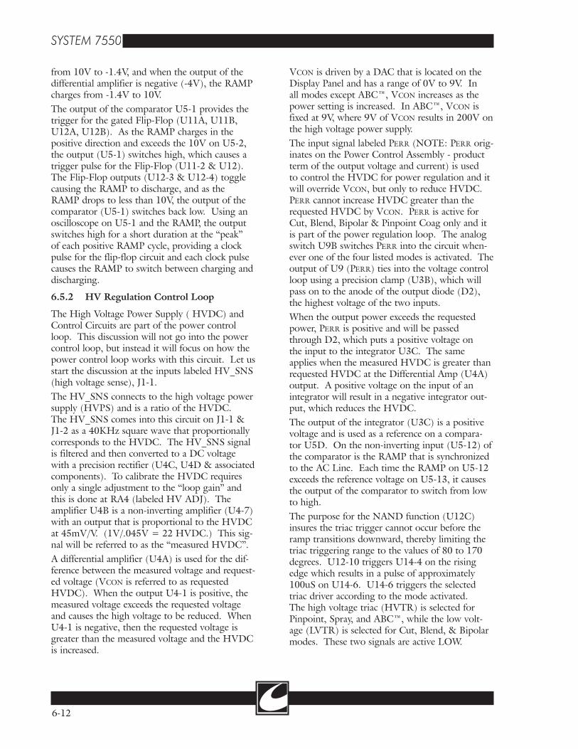
See Figure 6.3 for this section. Tank pressure indi-cated on the pressure gauge, located on the rear of the cart, is indicative of the quantity of remain-ing argon gas. A low pressure pneumatic/electric switch connected to the high pressure tank line closes if the tank pressure falls below approxi-mately 240 psi. Closure of this switch is used to warn the user of minimal remaining gas supply in the tank, indicated on the unit front panel by illuminating the yellow “low tank” indicator in the ABC™ section. The high pressure of the argon tanks is reduced to approximately 30 psi by a pneumatic regula-tor. If for any reason, pressure downstream of the pneumatic regulator should exceed 50 psi, a safety relief valve opens to minimize the risk of excessive pressure in the low pressure lines. Continuing downstream of the pneumatic circuit, a solenoid valve opens during ABC™ activation periods. This valve acts as a safety valve where it can be closed to shut argon flow off, if necessary. The proportioning valve is the controller for argon flow (solenoid and proportioning valve are on a common manifold) that increases and decreases gas flow as a result of the control signal developed by the control electronics. Immediately following the pneumatic manifold is a dampener to reduce any oscillations of the gas flow that may occur. The next element in the low pressure pneumatic circuit is the sensing orifice, recognizable by the five (5) ports for argon tubing connections. The sensing orifice is a calibrated
������������������������
������������
���� ����
����
����
�����
������������
���������
�����������
��������������������������������
�����������������
����������
��������
������������
����
��
������
������
����� ����
�������������������
���������������
������������
���������������������
���������������������
���������������
��
����������
��
Figure 6.3 Flow Diagram
6-14
restriction that provides flow rate information back to the flow control circuit. This orifice is the pneumatic equivalent of a current sense resistor. The differential pressure across the orifice is pro-portional to the flow rate, or simply, an increase in the flow rate increases the differential pressure as measured across the calibrated restriction.Three hoses from the sensing orifice connect back to the flow circuitry. Two of the hoses provide differential pressure information, while the third hose provides atmospheric pressure information. The atmospheric pressure information is used to compensate for usage at various altitudes. Lastly, the argon gas is filtered prior to delivery to the ABC™ handpiece accessory.
6.6.2 Mass Flow Rate Regulation
Referring to the HV/Flow Control Schematic (Figure C-4b), VGAS is an analog voltage for the mass flow rate and has a range of .5V to 6.2V. To enable the circuit, AR_EN must be SET causing U13-7 to go low. Signal control needs to be defined at this time. As mentioned, the System 7500™ has two (2)
microcontrollers on the display assembly. Each of the microcontrollers have control and monitor-ing responsibilities for argon flow. The Control Microcontroller sets the flow rate with Vgas (.5V - 6.2V) and enables the circuit with a SET on AR_EN. The Control Microcontroller can also monitor a predicted flow at FMEA. The Monitor Microcontroller opens the solenoid valve with a SET on GASEN and verifies the flow rate by monitoring the current through the flow control valve.The absolute pressure transducer (X2) measures the atmospheric pressure, plus the back pressure within the argon flow tubes when argon gas is flowing. This signal is referred to as PABS (TP4) and is calibrated for a specific voltage depending on the altitude where calibration occurs. Once calibrated, then PABS will automatically adjust to any change in altitude where the system may be placed into service. At sea level, PABS will be approximately 5.22V and at an altitude of one mile, PABS will measure about 4.13V. The differential pressure transducer (X1) has two hoses, or two input ports for argon hose connec-

6-15
tions. This component has an output proportion-al to the differential pressure across the calibrated restriction and the output is referred to as dP (TP3 - delta pressure). With the unit in standby only, dP is to be 0V. The PABS & dP signals are processed by an analog multiplier (U6), which results in a product term called “Q” (measured flow) at the cathode of D5 that is linearly propor-tional to the mass flow rate.With flow regulation, the voltage at D5 cathode or Q will be approximately the same as VGAS. A differential amplifier compares the difference in VGAS and Q at U8D. Should Q be greater than VGAS, U8-14 will be positive and when Q is less than VGAS, then U8-14 is negative. The integra-tor, U8B has an output of opposite polarity of the input (U8-6), and as an integrator, it controls the time at which the flow response can occur. The output of the integrator (U8-7) is always posi-tive with a range of approximately 1V (minimum flow) to 12V (maximum flow). The transistor Q2 is the driver for the proportioning control valve. The output signal labeled FMEA is monitored by the controlling microcontroller on the display assembly. This signal is one-half of the PABS volt-age and is a means of allowing the system to mon-itor the argon back pressure. FMEA has a range of 2V to 3.5V. The output signal labeled FMON is watched by the monitoring microcontroller on the display assembly as a means of verifying the proportion-ing valve current is within specified limits for each flow setting. FMON is calibrated at 4 lpm to be 2V. A loop failure that can cause flow to deviate from the requested flow or a shorted driver will be detected by FMON and the flow is inhibited by shutting off the proportioning valve.
6.6.3 Smart Sense
The System 7500™ utilizes “Smart Sense” to control the mass flow rate in different manners for each of the flow modes when a partial or total occlusion is detected. This discussion will be lim-ited to only Smart Sense response for each mode and what causes actions to occur.
• Automatic Mode: When a partial occlusion is detected in this mode, the flow rate is reduced by 1 lpm increments; or until the maximum back pressure occurs which will set an alarm. Flow reduction only occurs for flow settings
greater than 4 lpm; and for all dial settings that meet this criteria, the flow rate may be reduced down to 4 slpm. If the partial occlusion is removed, the flow will return to the original setting. Any change in the flow rate is displayed. A partial occlusion may be caused when the tip of the handpiece is in contact with the tissue, or by an accessory that has a small exit orifice; or a reduced exit orifice with a long nozzle. (NOTE: Some accessories cannot be used in the Automatic mode because the back pressure exceeds speci-fied limits - use manual mode instead.)
• Manual Mode: Smart Sense only tests for total occlusions in Manual mode. An occlusion alarm occurs with a back pressure greater than 7 psi within the argon flow tubes. This mode will not override user settings.
• Endo Mode: This mode will reduce flow rates when partial occlusions are detected, however at a different rate and for a different reason. With a flow setting greater than 2 lpm, a par-tial occlusion will reduce the flow rate down to 2 lpm. When the dial for flow is set for 2 or less, then the flow will only be reduced by .5 lpm. The purpose of the flow reductions is to allow a GI probe to be connected, auto-matically sensed, and the flow rate adjusted to optimize arc initiation.
6.7 Full Bridge Amplifier [A8]
Refer to Figure C-14 for this section. The Full Bridge Amplifier assembly houses the power switching devices (MOSFETS) that amplify respective drive waveforms for Cut, Blend, Bipolar, and Pinpoint modes of operation. The power FETS are arranged in an “H-bridge” con-figuration where two separate drive signals are alternately switched on to develop a push-pull action on the output transformer primary. The drive signals are referred to as 01 and 02 (phase 1 and phase 2) and each drive signal has a reset that is referred to as /01 and /02 (not phase 1 and not phase 2). Phase 1 (01) and Phase 2 (02) drive signals are developed on the Power Control Assembly and they are 180° out of phase. The /01 is turned on immediately after 01 is turned off and the same applies to /02. The /01 and /02 signals reset the magnetics of T1 & T2 allowing a faster turn off of the power devices. The drivers U1 & U2 step up the drive voltage from 5V to 12V.

6-16
Refer to the schematic (Figure C-14). Each drive cycle starts with 01 and the pulse width of this signal is approximately 1µS. The signal is ampli-fied from 5V to 12V at U1, turning on the driver FET Q2. The driver Q2 drain is pulled to ground allowing current flow from the center tap of T1. The secondary of T1 enables the power devices Q8 and Q17, allowing current flow from the HV Power Supply (+HV input). When Q17 switches on, it allows current flow from the +HV, through Q8, through C6, and the primary of the output transformer (connected to J2-1 & J2-2 - located on the RF Output Assembly ), and to -HV. This completes one-half cycle of a drive waveform.When 01 turns off, /01 and 02 switch on. The /01 “on-time” is only 200nS, long enough to switch on Q1 and pull the charge out of T1. The 02, however, works the same as 01, only it switch-es on the power devices Q9 & Q16, allowing current to flow from +HV, through Q9, and in the opposite direction of the output transformer (reversing the polarity) and then finally through Q16. This completes one full phase of RF drive on this amplifier. The switching action of alternately turning on 01 and 02 cause the primary of the output transform-er to have a positive and negative polarity. On the RF Output Assembly is the filter that converts the square wave generated by the amplifier to a sine wave that is delivered to the patient. The drive frequency is 461KHz, and the repetition rate of each cycle is 54µS. (See Figure 6.1.)
6.8 Single-Ended Amplifier [A9]
See Figure C-16 for this section. The Single Ended Amplifier assembly houses the power switching devices (MOSFETs) that amplify the drive waveforms for Spray and ABC™ modes of operation. The drive signals for this amplifier originate on the Power Control Assembly. The signal labeled SE is the drive signal and the one labeled /SE is only a reset pulse to reset the mag-netics of T1 & T2, and it has a pulse duration of about 200nS. The input signals are amplified by U1 from 5V to 12V. When SE switches from low to high, Q4 and Q2 are both switched on, and then when SE switches back to low, the /SE signal switches high to switch on Q3 and Q1. Each drive pulse (SE) enables all the power devices (Q9, Q17, Q8, & Q16) at the same time.
When the power devices switch on, viewed as a closed switch, the current flows from +HV, through the output transformer primary (+tank to -tank) and is passed to -HV. The current through the transformer primary is developing a charge that is stored in the primary of the trans-former. When the driver is turned off, viewing the power devices as open switches now, the charge stored in the primary is reversed and flows in the direction of +HV. It is during this time that the energy is delivered across the barrier to the secondary of the output transformer. The components C6 and primary of the output trans-former make up a “tank” circuit that can store a charge. When a load is not connected to the system output, then the current alternately flows from one side of C6 to the other until all the energy is dissipated.The repetition rate for a drive cycle is 35µS for Spray and the pulse width is fixed at about 1.3µS typically. (See Figure 6.1) The output power for the Spray mode is controlled by varying the HVDC. In ABC™, the power is controlled by varying the pulse width, and the HVDC is fixed at 200V. The pulse duration in ABC™ active is from 200nS to approximately 3µS.ABC™ has three separate modes that will be discussed in this section. The modes are Target, Booster, and Active. The modes Target and Booster alternately are active whenever a load is not present at the tip of the ABC™ handpiece. The Target mode is basically 1032 pulses at a 400nS pulse duration, and then the next 32 pulses will have a pulse duration of 600nS which is called the Booster mode. Following the Booster mode, the cycle starts all over again until a load is sensed at the ABC™ handpiece, and then the unit switches over to the Active mode. The repetition rate is also different for the ABC™ modes. Target and Booster have a drive pulse every 60µS, but in the active mode it occurs every 35µS. The purpose for the Target and Booster mode is to reduce the RMS voltage when a load is not present, and this results in lower RF Leakage. Once a load is present, which means the Beam is Active, RF Leakage is no longer an issue and the RMS voltage is increased to enhance performance.
6-17
6.9 RF Output Assembly/Components [A10]
The RF Output of the System 7500™ is essen-tially the secondary of three different output trans-formers, with only one of them actually located on the RF Output Assembly. When troubleshooting this assembly, caution must be taken on power set-tings and test leads connected, as voltage levels are rated in the thousands.Refer to the schematic (Figure C-18) and locate T3 primary. The connections labeled P2-1 and P2-2 connect to the Full Bridge Amplifier at J2-1 and J2-3. The reactive components on the secondary (C1 thru C7, L1 and L2) make up a bandpass filter that is calibrated for 461KHz. Following the filter are two transformers, T1 & T2. T1 is a current sense transformer with a 1:7 turns ratio. T2 is a voltage sense transformer with a 100:1 turns ratio. These transformers connect to the Power Control Assembly for output voltage and current monitoring (VSN and ISN). Relays K1 and K3 are normally open, and close any time Cut, Blend, Pinpoint or Bipolar modes are activat-ed. These relays switch the Full Bridge Amplifier Modes to the RF Output jacks.Locate on the schematic the transformer labeled Spray Output. This transformer is actually mounted to the chassis and can be identified by the color, which is black. The primary of this transformer is connected to the HS/A.R.M. Assembly (A11) along with the primary of the ABC™ transformer. The ABC™ transformer is mounted to the chassis and can be identified by the yellow color. Relays K2 & K4 are normally open, and close anytime Spray mode is activated. These relays switch the Spray mode to the RF Output jacks.On the outputs of K1-K4 is a transformer, T4, called a Balun. It has an additional winding called Balun sensing. A balun transformer helps mini-mize RF leakage during open circuit conditions. During “balanced” conditions, all the RF current leaving the RF amplifier exits and returns through the balun transformer. Under this ideal condi-tion, the magnetic fields within the balun created by the RF currents are equal and opposite. When the fields are equal and opposite, the net magnetic field is zero resulting in zero impedance presented to the RF output current.
If alternate current paths exist, some of the cur-rent exiting through the balun is returned to the amplifier via an alternate path. In this condition, the fields of the balun are not equal, presenting some degree of inductive impedance to the output current, limiting available alternate path leakage current. The impedance caused by the unbalanced current develops a magnetic field that is now greater than zero within the balun transformer, allowing for a single-turn winding that will sense the leakage.The magnetic field caused by RF leakage currents can develop a voltage that is proportional to the amount of leakage currents. With a balanced field within the balun, the sense winding has zero volts, and as the leakage increases, the voltage on the sense winding increases, allowing a circuit to be employed into the System 7500™ that will reduce output voltage when RF leakage is sensed.Each output of the system is discrete, or has an output relay with the exception of ABC™ Active. The active outputs are H1RF (handcontrol 1), H2RF (handcontrol 2), FTRF (footcontrol), and BPRF+H (Bipolar). In addition to the active outputs are the Patient Return which have three relays for isolation. K9 is closed only when ABC™ is activated to provide a return path back to the ABC™ output transformer. K8 is closed when Cut, Blend, Pinpoint or Spray is activated, and K11 is closed only when Bipolar is activated.The table below identifies which relays are closed for each of the modes activated.
Mode/Output Relays SelectedCut, Blend, Pinpoint (H1RF) K5, K8, K3, K1Cut, Blend, Pinpoint (H2RF) K7, K8, K3, K1Cut, Blend, Pinpoint (FTRF) K6, K8, K3, K1Bipolar K10, K11, K3, K1Spray (H1RF) K5, K8, K2, K4Spray (H2RF) K7, K8, K2, K4Spray (FTRF) K6, K8, K2, K4ABC K9
The A.R.M. connector is also located on the RF Output Assembly, however the A.R.M. circuit is on the HS/A.R.M. Assembly and will be cov-ered in that discussion. A failure due to a relay will obviously appear as low or zero RF Output Power. Finding the bad relay is not always obvi-ous, but when troubleshooting potential relay problems, start with the driver. The relay driver is

6-18
located on the Display Assembly, and one should first verify that each relay according to the table above is receiving a drive signal. Also, spend time to test all modes and all outputs as the “process of elimination” may be the fastest and most effective way to identify a faulty relay.
6.10 Low Voltage Power Supply [A6]
This assembly provides 5V, 15V, and -15V to the system circuits. A dedicated low voltage trans-former connects into the assembly at J1, where it is tapped for 18Vrms and 8Vrms. The regula-tors of this assembly only require a rectified and filtered input that is at least two volts greater than the output voltage. The regulators have current limit and thermal shutdown capabilities. A short-ed component on a different assembly can cause excessive current draw from a regulator, that will be limited, however the current draw will allow the regulator temperature to heat up until the thermal shut down is activated. There are two (2) 15V regulators, with Q1 dedi-cated to the FB Amplifier and SE Amplifier RF Drives. Q2 provides 15V for the system logic, indicators and relays. Regulator Q5 provides the -15V to the system to include the source for -10V and -5V that is used on the display panel. The 5V supply uses a small switcher type device because the 5V supply current can be close to 2A. A switcher operates more efficiently than a linear regulator (such as Q1, Q2, & Q5), not needing as much heat sink. As set up, the switcher oper-ates quite similar to the other regulators where the input must be greater than the output for voltage regulation to occur. The input to the switcher is 8Vrms and the output of the switcher is a square wave at 5V. The LC (L1 & C10) components convert the switching signal to a DC signal.Included on this assembly is the flow control pneumatic manifold. This manifold assembly has the solenoid valve (one nearest front) and flow control (proportioning valve) assembled within it, and if one should fail, then both must be replaced. The proportioning valve is current controlled so as the current is increased, the internal opening is increased allowing more argon gas to flow. The solenoid valve is also referred to as a digital valve, meaning it is either on or off.To test the valve coils, place a DVM or oscillo-scope on the driver for the device under test. The coil resistance of both valves is 72 ohms. The
proportioning valve voltage changes with the flow setting (V=IR). The collector of the driver for the digital valve will switch from 15V to near ground when the valve is energized, as the valve drops almost all of the voltage.
6.11 HS/A.R.M. Assembly [A11]
There are four independent and unrelated cir-cuits on this Board Assembly. Each circuit will be covered separately. The HS/A.R.M. assembly is located near the front of the system and is the top circuit board of the two that are stacked. (See Figure C-20.)
6.11.1 Handsense Circuit
The Handsense circuit is comprised of three iso-lated Handcontrol circuits with each handcontrol circuit dedicated to Monopolar Handcontrol (handcontrol 1), Beam/Monopolar Handcontrol (handcontrol 2), or Bipolar. Handcontrol 1 allows activation of either Cut or Coag. Handcontrol 2 allows activation of either Cut, Coag or ABC™. Bipolar allows activation of bipolar when using hand activation forceps.The components that provide electrical isolation between the control circuits and the RF circuits are T3 (continuity transformer) and U4-U8 (optoisolators). On the control side of the bar-rier, U3 (NE555 timer) provides a 100KHz drive signal at a 20% duty cycle for T3 primary. The secondary winding of T3 provides energy for the handcontrol sense electronics on the high volt-age side of the isolation barrier. The bipolar handswitch continuity detector will be used as an example, since all sections are identical.When the bipolar handswitch is closed, DC cur-rent flows through the LED of the opto-isolator, U7. The LED produces a beam of light which falls on the photo transistor in U7 causing it to switch on and draw current. This current pulls the signal line /HBP to a low voltage, and this state is interpreted on the Display Assembly as a switch closure. When the handswitch is released, the LED goes dark causing the photo transistor to cease conduction and allow the signal line to be pulled high by a resistor network located on the display PCB.Handcontrol 1 and Handcontrol 2 sense circuits operate in the same manner for Cut or Coag requests. An exception, however, is an ABC™ activation sensed as a result of both Cut and Coag photo transistors being in the ON state during
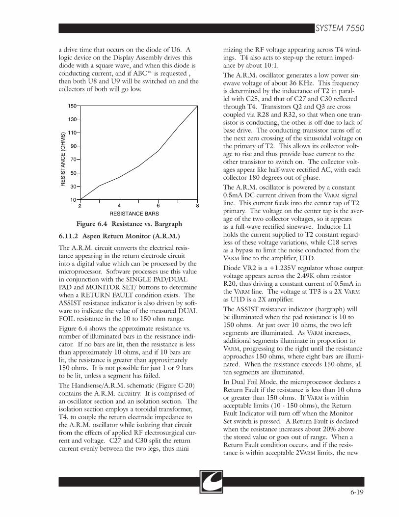
150
130
110
90
70
50
30
102 4 6 8
RE
SIS
TA
NC
E (
OH
MS
)
RESISTANCE BARS
Figure 6.4 Resistance vs. Bargraph
6-19
a drive time that occurs on the diode of U6. A logic device on the Display Assembly drives this diode with a square wave, and when this diode is conducting current, and if ABC™ is requested , then both U8 and U9 will be switched on and the collectors of both will go low.
mizing the RF voltage appearing across T4 wind-ings. T4 also acts to step-up the return imped-ance by about 10:1.The A.R.M. oscillator generates a low power sin-ewave voltage of about 36 KHz. This frequency is determined by the inductance of T2 in paral-lel with C25, and that of C27 and C30 reflected through T4. Transistors Q2 and Q3 are cross coupled via R28 and R32, so that when one tran-sistor is conducting, the other is off due to lack of base drive. The conducting transistor turns off at the next zero crossing of the sinusoidal voltage on the primary of T2. This allows its collector volt-age to rise and thus provide base current to the other transistor to switch on. The collector volt-ages appear like half-wave rectified AC, with each collector 180 degrees out of phase.The A.R.M. oscillator is powered by a constant 0.5mA DC current driven from the VARM signal line. This current feeds into the center tap of T2 primary. The voltage on the center tap is the aver-age of the two collector voltages, so it appears as a full-wave rectified sinewave. Inductor L1 holds the current supplied to T2 constant regard-less of these voltage variations, while C18 serves as a bypass to limit the noise conducted from the VARM line to the amplifier, U1D.Diode VR2 is a +1.235V regulator whose output voltage appears across the 2.49K ohm resistor R20, thus driving a constant current of 0.5mA in the VARM line. The voltage at TP3 is a 2X VARM as U1D is a 2X amplifier.The ASSIST resistance indicator (bargraph) will be illuminated when the pad resistance is 10 to 150 ohms. At just over 10 ohms, the two left segments are illuminated. As VARM increases, additional segments illuminate in proportion to VARM, progressing to the right until the resistance approaches 150 ohms, where eight bars are illumi-nated. When the resistance exceeds 150 ohms, all ten segments are illuminated.In Dual Foil Mode, the microprocessor declares a Return Fault if the resistance is less than 10 ohms or greater than 150 ohms. If VARM is within acceptable limits (10 - 150 ohms), the Return Fault Indicator will turn off when the Monitor Set switch is pressed. A Return Fault is declared when the resistance increases about 20% above the stored value or goes out of range. When a Return Fault condition occurs, and if the resis-tance is within acceptable 2VARM limits, the new
6.11.2 Aspen Return Monitor (A.R.M.)
The A.R.M. circuit converts the electrical resis-tance appearing in the return electrode circuit into a digital value which can be processed by the microprocessor. Software processes use this value in conjunction with the SINGLE PAD/DUAL PAD and MONITOR SET/ buttons to determine when a RETURN FAULT condition exists. The ASSIST resistance indicator is also driven by soft-ware to indicate the value of the measured DUAL FOIL resistance in the 10 to 150 ohm range.Figure 6.4 shows the approximate resistance vs. number of illuminated bars in the resistance indi-cator. If no bars are lit, then the resistance is less than approximately 10 ohms, and if 10 bars are lit, the resistance is greater than approximately 150 ohms. It is not possible for just 1 or 9 bars to be lit, unless a segment has failed.The Handsense/A.R.M. schematic (Figure C-20) contains the A.R.M. circuitry. It is comprised of an oscillator section and an isolation section. The isolation section employs a toroidal transformer, T4, to couple the return electrode impedance to the A.R.M. oscillator while isolating that circuit from the effects of applied RF electrosurgical cur-rent and voltage. C27 and C30 split the return current evenly between the two legs, thus mini-

6-20
value can be locked into memory and the Return Fault condition will be cleared.
6.11.3 RF Leakage Monitor
The System 7500™ actively monitors alternate path RF leakage currents caused by stray parasitic capacitance and limits the available open circuit voltage in response to prevailing leakage condi-tions. This circuit is primarily active in Spray Coag mode, but is available in all modes of opera-tion except ABC™.The balun transformer description was covered in the RF Output Assembly discussion, where it was stated that the magnetic field is equal and oppos-ing if the source and returning RF currents are equal. If the source and returning currents are not equal, alternate leakage paths exist and the balun transformer field becomes unbalanced, resulting in restriction of the available output current due to the inductive impedance of the transformer. The balun transformer has a single turn winding that has currents induced within it when a magnetic field of the balun is unequal due to RF leakage.The RF Leakage sense winding connects to J16 on the HS/A.R.M. assembly. The signal at J16 is an AC voltage that is converted to a DC volt-age at U2, which is an RMS-DC converter. The true RMS voltage is compared with a reference DC voltage representative of maximum allow-able alternate path leakage current at U1B. If the leakage exceeds the limit value as set by R15, J1-5 slews positive. The positive signal at J1-5 is supplied to the HV/FLOW Control Assembly to limit the High Voltage Power Supply output (HVDC). Limiting or reducing the High Voltage Output results in reduced RF Leakage.
6.11.4 Transformer Select Relays
The ABC™ and Spray Coag transformers, along with the associated tuning capacitors, are coupled to the Single Ended Amplifier (SE Amplifier) by relays K1 and K2 on the HS/A.R.M. assembly. These relays switch into the circuit the primary of the appropriate transformer, depending on the mode requested.The default or normally closed position of the relays selects the ABC™ transformer. The relay driver is located on the Power Control Assembly. When Spray Coag is activated, J2-5 is pulled low, allowing current to flow through the relay coils to energize them.
6.11.5 Arc Sense Transformer
The Arc Sense Transformer, connected with the -TANK terminal in ABC™ mode, sends a propor-tional sample of tank ring-down voltage to the Power Control assembly. This sample signal is used to determine if the ABC™ amplifier is loaded (a heavily damped output signal) or open circuit (lightly damped output signal). With a lightly damped output signal, a peak detector on the Power Control assembly provides a switching sig-nal for each peak that exceeds a predetermined ref-erence. The circuit monitoring for loaded or open circuit outputs will assume an open circuit if four peaks within each drive cycle exceeds the limits. The output signal voltage and duty cycle is depen-dent on whether the output is loaded or open.The transformer is switched into the circuit by the relays K1 and K2, and only for ABC™ mode. When Spray is activated, the relays remove the Arc Sense Transformer from the circuit.
7-1
7.1 Introduction
This section contains information on system main-tenance and checkout procedures. A new system should be tested to insure it is in proper working order before being placed into service. Included in this section are:
• Cleaning• Generator & Mobile Storage Assembly• Factory Default Settings• AC Mains - Voltage & Frequency Settings• Accessory Connections• System Testing
Instrument repair or calibration should only be performed by personnel trained in electronic medical equipment service. If the CONMED 7550 Electrosurgical Generator + ABC™ is under warranty, refer to the warranty information on the inside front cover of this manual.Abbreviated terms used throughout this section:
• ABC™ - Argon Beam Coagulator• ESU - Electrosurgical Unit (System 7550)• A.R.M.- Aspen Return Monitor
7.2 Cleaning
The interior of the unit may be vacuumed or blown out as required. The exterior of the unit may be cleaned by wiping it down with a damp (not dripping) cloth. Use a mild detergent such as Windex® or Formula 409®.
7.3 Generator & Mobile Storage Assembly
The System 7550 consists of a Generator assembly (Head Assembly) and a Mobile Storage assembly (Cart). In most cases, the two are shipped pre-assembled. To disassemble the two, follow the assembly steps below in reverse order. Refer to page 2-3 of the Operator Manual.CAUTION: The Generator (Head) assembly is heavy and awkward. Lifting of the Head on or off of the Cart should be done by two (2) people to reduce the risk of injury.
Maintenance/CheckoutSection 7.0
1. Set the Head Assembly on the Cart (the argon tanks are placed on the back of the cart).
2. Insure the Head Assembly is fully seated on the Cart. Notice that the Head has four (4) threaded studs that drop down into the Cart.
3. Locate the two threaded studs that are inside the Cart, but against the back wall. Place a wing nut on each of the two back studs, but thread the wing nuts on the studs by only two or three turns.
4. With one person supporting the Head, tilt the Head Assembly towards the back of the Cart. This allows access to the footswitch connector and argon gas line.
CAUTION: The Head Assembly is heavy and can topple off backwards if not supported - the two wing nuts on the two back studs will help with the support, but will not keep the head from tipping the cart backwards if the head is not properly supported.
5. Locate the wiring harness with the 15 pin connector within the Cart. Connect the har-ness to the connector on the bottom of the Head Assembly. The connector is keyed so it can only be plugged in one way.
6. Locate the nylon argon gas tube within the Cart. Connect the argon gas tube to the con-nector on the bottom of the head. The fitting on the gas tube will “snap” into place when inserted into the mating connector on the bottom of the Head.
To DISCONNECT the argon gas tube, press the release button on the side of the fitting. When the button is pressed, the argon gas tube can easily be pulled out of the mating connector. Do not pull on the gas tube as it is easily damaged.
7. Set the Head back down onto the Cart. Add the two remaining wing nuts to the studs within the Cart to secure the Head to the Cart. Insure all four (4) wing nuts are tight-ened.
7-2
8. Connect the Power cord to the power recep-tacle located on the back side of the Head assembly. Directly below the power receptacle is a strain relief. Use the strain relief to secure the power cord to the Cart.
7.4 Access to Circuits & Factory Settings
1. Remove the two screws located on either side of the front portion of the top cover.
2. Lift the top cover and lock the cover support hinge.
3. Verify all internal assembly wiring harnesses and cables are securely connected. This is best done by pressing on each connector to ensure they are seated.
4. Visually inspect the bottom of the inside of the Head assembly for any loose hardware.
7.5 Default Settings (Factory Settings)
Each time the System 7550™ is powered on, it will initialize to the default modes. Four (4) of the default settings can be changed to best fit the user requirements. To change the system default settings, locate the micro switch on the back side of the Display PCB. Viewing the switch with the cover raised, down is OFF and up is ON. The positions are numbered from left to right. All default settings are OFF or down from the factory.
• Pos 1 (Default - Run Mode)ON: Test Mode: For system troubleshooting
only• Pos 2 (Default - Dual Pad)
ON: Single Pad• Pos 3 (Default - Last Power Setting)
ON: All Powers initialize to 0W• Pos 4 (Default - Pinpoint)
ON: Spray• Pos 5 (Default - Simultaneous Activation)
ON: Non-Simultaneous Activation • Pos 6 (Default - ABC Argon Monitor
enabled)ON: ABC Test Mode - Allows ABC testing
without argon gas & inhibits argon flow alarms.
1. TEST MODE: When this switch is ON, the internal monitoring is shut off, allowing system
testing without mode inhibits shutting the system down.WARNING: DO NOT PLACE UNIT IN SERVICE WITH TEST MODE ON.
• The TEST MODE can be enabled anytime when the Power is on.
• If TEST MODE is selected when the unit is powered on, an Err 20 is displayed. An Err 20 can only be cleared with a system power down or reset.
• To Power Up with the TEST MODE enabled, hold down the STORE switch on the Front Panel until an Err 1 is displayed. This allows the system to be powered on when error mes-sages occur during system diagnostics.
2. ABC TEST MODE: When this switch is ON, the ABC Mode can be tested without argon gas flow.WARNING: DO NOT PLACE UNIT IN SERVICE WITH ABC TEST MODE ON.
• The ABC Test Mode can be enabled anytime when the Power is on.
• If ABC TEST MODE is selected when the unit is Powered on, an Err 20 is displayed. An Err 20 can only be cleared with a system power down.
• To Power Up with the ABC TEST MODE enabled, hold down the STORE switch on the Front Panel until an Err 1 is displayed. This allows the system to be powered on when error messages occur during system diagnos-tics.
7.6 AC Mains Frequency & Voltage
The unit is shipped with the AC Mains Frequency properly set for the unit destination. However, if the label on back of the system has the frequency listed as 50/60 Hz, then it may be necessary to verify the selected frequency is set correctly.
1. Mains Frequency:Reference Figure C-1 for this section.
• Remove the cover from the PCB card cage. The card cage is located at the right rear of the the unit. Two (2) PCB assem-blies are within the card cage.
• On the right side of PCB assembly A1 is a switch. The system is configured for 50 Hz when the switch is to the left and 60 Hz when the switch is to the right.

7-3
• Ensure the switch is in the correct position for the frequency for which the system will be placed in service.
• Replace the card cage cover. 2. Mains Voltage:See Figure C-1 for this section.
• To verify the correct Mains Voltage con-figuration, locate the terminal block that is above and behind the large line trans-former. In the center of the terminal block are shorting plugs and on the front of the terminal block are numbers to identify each position. A system config-ured for 120V or 100V will have five (5) shorting plugs. A system configured for 210-240V system will have only three (3) shorting plugs. The shorting plug loca-tions are:
• 120V & 100V: 1-2, 2-3, 4-5, 6-7, 7-8• 210-240V (Rated range 198V to 260V):
1-2, 5-6, 7-8NOTE: The terminal block configuration is shown on the interconnect diagram (Figure C-2).
• Close the cover and secure with the two screws located on both sides.
7.7 Initial Setup & Test
Performing this procedure will verify functional operation of the CONMED 7550 Electrosurgical Generator + ABC™. A system error detected on “power up” will be displayed as an error code. (See error codes in Troubleshooting, Appendix B)The testing of this section does not test or verify system calibration, but only if the unit is func-tioning from a user perspective. The calibration section provides procedures for full system testing and calibration.Figure 7.1 is a listing of test leads that are needed to test the System 7550™. To test the output power during the functional testing, the test leads are necessary. However, if the output power is not tested, then only the accessories are necessary.
7.7.1 Accessory Connections
1. Connect a handcontrol accessory to the Monopolar Handcontrol Jack (Handcontrol 1).
2. To test the ABC™ mode with a handcontrol switched accessory, it must be connected to the Beam/Monopolar Handcontrol
Jack (Handcontrol 2). A Triple Option Handcontrol Accessory connected to Handcontrol 2 will allow activation of Cut, Coag, & ABC modes. Fasten the connector of the ABC™ accessory to the Argon Beam Coagulator connector.
3. Connect a Patient Plate adapter from the Dispersive Electrode receptacle to an ESU analyzer.
4. Set the electrosurgical analyzer load for 500 ohms to test all modes except bipolar. Bipolar load should be 100 ohms.
Note: To test bipolar output power, use test leads. Connect the test leads to the two bipolar RF out-put jacks of the ESU and the other end to the 100 ohm load. To activate bipolar, use a footswitch if available, and if not, use a third test lead to short out the right RF output receptacle to the bipolar hand sensing receptacle located just above the RF output receptacles.
5. Connect all three footswitches (Monopolar, ABC™, & Bipolar) to the footswitch recep-tacles located on the Mobile Storage Pedestal (Cart).
6. Connect a tank of argon gas. Ensure the tank is securely fastened to the cart with the tank strap. Once the tank connector is securely fastened to the tank, turn the tank valve fully counter-clockwise and verify the argon tank has at least 200 psi for test purposes.
7. Insert a Footcontrol adaptor into the Footcontrol jack. When testing output power using an ESU analyzer, it is recommended to use a test lead from the Footcontrol jack to the ESU analyzer, and use footswitches to activate the system.
7.7.2 Display Panel Testing
1. Connect the power cord to a grounded AC outlet and press the main switch/breaker to turn the system on.
2. Verify during system initialization that:• Displays “88” on ones and tens digits.• Displays “3” on all hundreds digits.• All mode indicators illuminate.• An audible tone of variable frequency
occurs.• An error code (Err) is not displayed in the
cut window (See Err in Troubleshooting if displayed).

7-4
3. Verify the system defaults to the following modes:
• Pure Cut (Display above Blend knob dis-plays “0”).
• Pinpoint Indicator is illuminated.*• Endo indicator is illuminated.• Dual Foil Return Electrode indicator is
illuminated.**The factory default settings can be changed by the user.
4. Rotate each knob and verify all displays are working correctly. Check for missing seg-ments or segments that are latched on.
• Cut Range: 0 - 300W• Blend Range: 0 - 200W• Pinpoint Range: 0 - 120W• Spray Range: 0 - 80W• Bipolar Range: 0 - 70W• ABC™ Range: 0 - 150W (Endo Mode) 10-150W (Auto & Manual Modes)• Blend Modes: 1 - 9
5. Argon Flow Control Modes:Argon Flow Control has three independent
modes. Listed below are the flow rates and limits based upon the ABC™ power setting for each mode.
• Endo Flow: 0.1 - 4 slpm @ 0.1 slpm increments. Flow rate is manually adjust-ed with limits based upon the power set-ting.
ABC Power Range (W) Flow Range (SLPM)
0-20 0.1 - 2.0
21-40 0.5 - 2.0
41-80 1.0 - 3.0
81-150 2.0 - 4.0
• Automatic Flow: 1 - 10 slpm @ 1 slpm increments. Flow rate is automatically adjusted with the ABC™ power.
ABC Power Range (W) Flow Range (SLPM)
10-19 1.0
20-24 2.0
25-29 3.0
30-34 4.0
35-39 5.0
40-49 6.0
50-89 7.0
90-109 8.0
110-129 9.0
130-150 10.0
• Manual Flow: 0.5 - 10 slpm • 0.5 - 4.0 slpm: 0.1 slpm increments • 4.0 - 6.0 slpm: 0.2 slpm increments • 6.0 - 10. slpm: 0.5 slpm increments
ABC Power Range (W) Flow Range (SLPM)
10-39 0.5 - 4.0
40-79 2.0 - 8.0
80-150 4.0 - 10.0
6. Press the following dome switches and verify the indicator for each switch pressed is illumi-nated.
• Automatic in ABC section• Manual in ABC section• Endo in ABC section• Single Return Electrode in Return
Monitor Section• Dual Return Electrode in Return Monitor
Section• Remote in Power Control• Spray in Coag Section• Pinpoint in Coag Section
7. Press Purge in the ABC section. Verify that:• Flow rate window has a “4” displayed.• Argon flow occurs for approximately “4”
seconds.• An audible tone occurs during the purge
time.
7-5
7.7.3 Activation Testing
Caution: Handcontrol accessory electrodes can cause RF burns if touched during activation, even if the handcontrol accessory is not the one that is activated. Place unused accessories into a suitable insulated cup or holster.Set the power for all modes to 10W or less. (RF Load is not required for the following testing.)
1. Handcontrol 1 (Monopolar handcontrol)• Activate Cut (yellow button on
handcontrol). Verify an audible tone occurs and the yellow indicator in the cut section illuminates.
• Activate Coag (blue button on handcontrol). Verify an audible tone occurs and the blue indicator in the coag section illuminates.
2. Handcontrol 2 (Beam/Monopolar Handcontrol)
• Activate Cut (yellow button on handcontrol). Verify an audible tone occurs and the yellow indicator in the cut section illuminates.
• Activate Coag (blue button on handcontrol). Verify an audible tone occurs and the blue indicator in the coag section illuminates.
• Activate ABC (light blue button on handcontrol). Verify an audible tone occurs and the blue indicator in the ABC section illuminates.
3. Bipolar Handcontrol• Bipolar handcontrol activation can be veri-
fied using forceps with handswitching capabilities or using a test lead between the right (when facing the system) Bipolar RF jack and the hand sensing jack located above and between the two bipo-lar RF jacks. Verify a tone occurs and the blue indicator in the bipolar section illuminates.
4. Footcontrol Testing • Activate Cut footswitch and verify an
audible tone occurs and the yellow indica-tor in the cut section illuminates.
• Activate Coag footswitch and verify an audible tone occurs and the blue indicator in the coag section illuminates.
• Activate ABC footswitch and verify an audible tone occurs and the blue indicator in the ABC section illuminates.
• Activate bipolar footswitch and verify an audible tone occurs and the blue indicator in the bipolar section illuminates.
7.7.4 RF Output Power Checks
Refer to Figure 7.2 for this section. Power test-ing for Cut, Blend, Pinpoint & Spray can be per-formed using a handcontrol accessory. However, if a footcontrol adaptor is available, connect a test lead from the Monopolar Footcontrol jack to the ESU analyzer. If a footcontrol adaptor or the footcontrol switches are not available, then mea-sure output power from one of the handcontrol accessory electrodes. To measure Bipolar power, connect the ESU ana-lyzer between the two bipolar RF jacks using test leads.To measure ABC™ power, an ABC test adaptor is required. Connect the ESU analyzer between the Argon Beam Coagulator connector and the Return Electrode Receptacle.If measured power is out of the listed range, refer to the calibration section for power calibration. The power range is to allow for power differences in analyzers. The specified power settings are only suggested, but it is recommended that at least two different power settings be tested in all modes. (Blend can be an exception.)
1. Select Pure Cut (Blend Display reads “0”)• Set power to 50W - Activate Cut and
verify 50W (45W-55W).• Set power to 300W - Activate Cut and
verify 300W (270W-325W).2. Select Blend (Blend Display reads 1-9)
• Set power to 50W.• Activate Cut and verify 50W (45W-55W).
3. Select Pinpoint Coagulation• Set power to 50W - Activate Coag and
verify 50W (45W-55W).• Set power to 120W - Activate Coag and
verify 120W (110W - 130W).4. Select Spray Coagulation
• Set power to 25W - Activate Coag and verify 25W (20W - 30W).
• Set power to 80W - Activate Coag and verify 80W (72W - 88W).

7-6
5. Bipolar Coagulation - (Load - 100 ohms)• Set the power to 20W - Activate Bipolar
and verify the power is 20W (15W - 25W).
• Set the power to 70 ohm - Activate Bipolar and verify the power is 70W (62W - 77W).
6. Argon Beam Coagulation - (Load - 500 ohms)
• Set the power to 20W - Activate ABC™ and verify the power is 20W (16W - 24W).
• Set the power to 150W - Activate ABC™ and verify the power is 150W (135W- 165W).
7.7.5 Argon Flow Testing
A mass flow meter calibrated for argon gas is required to measure and verify argon flow rates. However, if a flow meter is not available, the flow can be tested and verified so as the flow setting is increased, the flow rate increases. An ABC™ accessory is required to test the argon flow rate.In the previous section for Display Panel testing, three (3) tables listed flow limits as related to ABC™ power settings. Refer back to the tables or keep in mind that when the argon setting does not increase or decrease beyond present settings, the ABC™ power is forcing the limit.Smart Sense can change the initial flow setting during an activation interval if the back pres-sure caused by the accessory or any other type of partial occlusion exceeds internal limits. When testing the flow rates, the measured flow should match that of the displayed flow rate.
1. Without an Argon Calibrated Mass Flow Meter:
• Select Manual flow mode. Set the flow to 4 slpm and power to 50W. Activate ABC™ into a 500 ohm load. The flow of the argon will typically be audible, but a beam will only occur if the gas is flowing. A typical beam length at these settings is close to 1cm.
• Increase the flow in increments of 1 slpm and for each setting, activate into a load. Verify a beam occurs and has a length greater than 5mm. To get more than 8 slpm of flow, the power must be greater than 80W.
2. With an Argon Calibrated Flow Meter:• Insure the nozzle of the ABC accessory is
seated within the intake hose of the meter to minimize leaking. A leak in the con-nection will give false readings.
• Flow should be checked at 2, 4, & 8 slpm as a minimum. The flow is calibrated at the factory and is within specifications if the flow is ±.6 slpm. If the flow rate is not correct, go to the calibration section of this manual.
7.7.6 Remote Power Control Testing
A standard “2 button” handcontrol is sufficient to test the Remote Power Control, however it will only allow testing of Cut and Coag modes. ABC™ Remote Power Control can be tested with a Triple Option ABC™ accessory.
1. Press the “Remote” front panel switch. Ensure a handcontrol is connected to either Monopolar Handcontrol or Beam/Monopolar Handcontrol jacks. (ABC™ handswitchable accessories must be connected to the Beam/Monopolar Handcontrol jacks.)
2. Rapidly “double press” or “double click” the CUT (yellow) button on the handcontrol. The Cut display will flash when the Remote Power mode is active and the tone will change. (If the displays do not flash, it typi-cally means the double press did not occur within a specified time of 400mS. Try the function again.)
• To advance the power setting, press the Cut button - to reduce the power setting, press the Coag button.
• With the power <20W, the power changes in 1W increments.
• With the power ≥ 20W, the power chang-es in 5W increments.
• A brief tone occurs each time the power changes.
• To exit the Remote Mode, double press the Cut button or wait 5 seconds and the system will automatically exit the Remote Mode.
3. Rapidly “double press” or “double click” the COAG (blue) button on the handcontrol. The Coag display will flash when the Remote Power mode is active and the tone will change. (If the displays do not flash, it typi-

7-7
cally means the double press did not occur within a specified time of 400mS. Try the function again.)
• To advance the power setting, press the Cut button - to reduce the power setting, press the Coag button.
• With the power <20W, the power changes in 1W increments.
• With the power ≥20W, the power changes in 5W increments.
• A brief tone occurs each time the power changes.
• To exit the Remote Mode, double press the Coag button or wait 5 seconds and the system will automatically exit the Remote Mode.
4. Rapidly “double press” or “double click” the ABC™ (light blue) button on the handcontrol. The ABC™ display will flash when the Remote Power mode is active and the tone will change. (If the displays do not flash, it typically means the double press did not occur within a specified time of 400mS. Try the function again.)
• To advance the power setting, press the Cut button - to reduce the power setting, press the Coag button.
• With the power <20W, the power changes in 1W increments.
• With the power ≥20W, the power changes in 5W increments.
• A brief tone occurs each time the power changes.
• To exit the Remote Mode, double press the ABC™ button or wait 5 seconds and the system will automatically exit the Remote Mode.
7.7.7 Return Monitor (A.R.M. - Aspen Return Monitor)
The return monitor allows a Single Foil Dispersive Electrode or Dual Foil Dispersive Electrode to be connected to the System 7550.
1. Select Single Pad• The A.R.M. tests for resistance at the pad
site of 10±2 ohms.• To test the A.R.M. parameters for a Single
Pad, connect a decade resistance box
(DRB) or discrete resistors across the two conductors of a patient plate cord.
• With resistance < 8 ohms, Return Fault indicator is off. With resistance > 12 ohms, Return Fault indicator is flashing.
• Verify that when the Return Fault indica-tor is flashing, an audible alarm occurs if any mode but bipolar is activated.
2. Select Dual Pad• The A.R.M. tests for resistance at the pad
site of greater than 10±2 ohms and less than 150±5 ohms.
• To test A.R.M. in Dual Pad, it is recom-mended a decade resistance box (DRB) be connected across the two conductors of a patient plate cord. If a DRB is not available, discrete resistors can be used.
• Ensure Dual Pad is selected.• Resistance < 5 ohms: Bargraph off -
Return Fault indicator is flashing.• Resistance = 12 ohms: Two (2) bargraph
segments flashing; Monitor Set indicator flashing; Return Fault indicator flashing.
• Press Monitor Set: Two (2) bargraph segments on; Monitor Set indicator on; Return Fault indicator off.
• Resistance = 20 ohms: Three (3) bargraph segments flashing; Monitor Set indicator flashing; Return Fault indicator flashing.
• Press Monitor Set: Three (3) bargraph segments on; Monitor Set indicator on; Return Fault indicator off.
• Resistance = 130 ohms: Eight (8) bargraph segments flashing; Monitor Set indicator flashing; Return Fault indicator flashing.
• Press Monitor Set: Eight (8) bargraph segments on; Monitor Set indicator on; Return Fault indicator off.
• Resistance = 160 ohms: Ten (10) bargraph segments flashing; Monitor Set indicator flashing; Return Fault indicator flashing.
• Press Monitor Set: It will remain in the Alarm Mode. Each time the Monitor Set is pressed, an alarm tone will be gener-ated.
7-8
7.8 Pulsed Cut Mode
Pulsed Cut is a mode that delivers RF energy in pulsed durations for precise control of dissection. The repetition rate of Pulsed Cut is approximately 640mS with RF “ON” time of approximately 75ms and RF “OFF” time of approximately 565mS for a duty cycle of 12%. The activation tone consists of two different frequencies, with the higher frequency being the tone that identi-fies when RF is delivered and the lower frequency tone identifying when the RF is off. The power delivered during the RF “ON” time of the Pulsed Cut is the power that is displayed in the Cut win-dow, so the rms power is approximately 12% of the displayed power.To select the Pulsed Cut mode, press the “Down” switch in the Program section on the Front Panel until “P” (P for Pulsed) is displayed. When select-ing Pulsed Cut, all power levels on the display panel will be set to zero, therefore all power levels will have to be adjusted to desired settings. When leaving the Pulsed Cut mode, all powers will also be set to zero. Because of the low repetition rate, it is difficult to measure the rms power using stan-dard electrosurgery analyzers, therefore to test this mode, use an oscilloscope and verify the output or RF drive on the Full Bridge (30-0134 assy.) are pulsed at a rate of approximately the values listed above.To test the RF output with 1:1 or 10:1 scope probes, simply lay the scope probe cable across a lead connected to the dispersive electrode. Do not connect the scope probe directly to the lead as damage may occur to the probe. Set Cut power to about 50W into a 500 ohm load and set the scope for 100mS/Div. Activate Pulse Cut and verify the output is pulsed.
7.9 RF Leakage Test
See Calibration Section for Test and Calibration of RF Leakage.
7.10 Final Checks
1. Ensure the internal switch setting is set for Run Mode and ABC Argon Monitoring Mode. This can be verified by turning on the Main Power. If an Err 20 is displayed, the default switch settings are not properly set. (Positions 1 and 6 should be down or off.)
2. Ensure the lid or cover is secured by the two screws on either side.
3. Ensure the argon tank valve is off. The pres-sure within the argon lines will not bleed off and it is not necessary to bleed the lines.
4. Ensure the Power Cord is secured by the strain relief that is connected to the argon tank strap support.
7.11 Mobile Storage Pedestal (Cart)
The System 7550 Mobile Storage Pedestal (Cart) houses the High Pressure pneumatics, pressure relief valve, tank pressure switch, tank pressure gauge, and wiring harness for the footswitch con-nectors. A block diagram of the argon pneumat-ics within the cart is shown in figure 6.3 on page 6-15. There are no requirements for annual main-tenance on any components within the Cart.The argon tank pressure input is rated for 3000 psi and is stepped down to 30 psi using a dual stage pressure regulator assembly. The first stage of the dual stage pressure regulation reduces the tank pressure down to approximately 175 psi and the second stage reduces the 175 psi down to 30 psi. The output of the second stage regulator connects to a fitting that carries the argon into the Generator Assembly and has a 50 psi pressure relief valve. In the event a pressure regulator fails, the pressure relief valve will open and vent the argon in the atmosphere so that argon tubes are not ruptured.The low pressure switch and pressure gauge are both on the input side to the dual stage pressure regulator assembly. The pressure gauge measures the pressure within a tank of argon that is con-nected. The “low tank” pressure switch is simply a set of contacts that are held “open” when the tank pressure is greater than 250 psi and close at lower pressures. When the switch closes, a yellow indicator on the display panel flashes to inform the user that the argon supply is low.WARNING: Input pressure lines can hold up to 3000 psi (200 bars) of pressure. Do not attempt service of pneumatic components within the cart before disconnecting the tank of argon. Replacement of any pneumatic com-ponents within the cart should have all fittings sealed with pipe sealant to prevent slow leaks. Soapy water should be applied to all fittings to insure proper sealing against small leaks.

���������������
��������������������
�����������������
���������
����������������
�������������������
�
Figure 7.1 Test Adapters
7-9
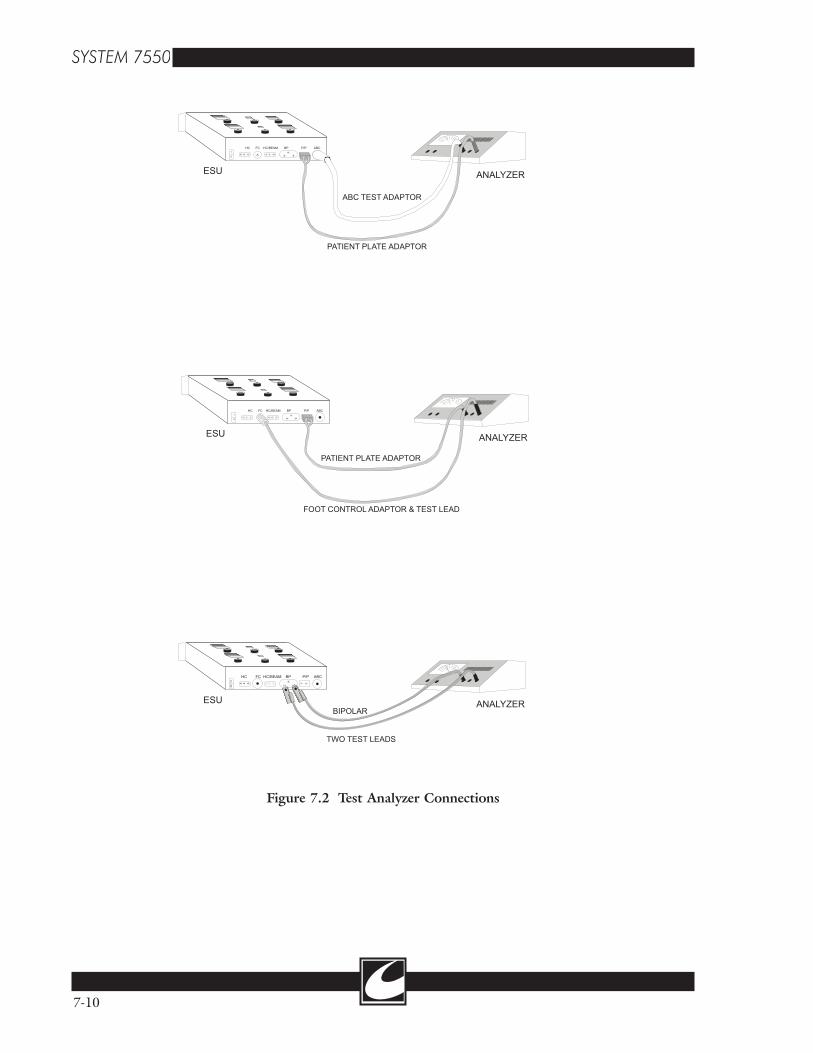
�
�
�� �� ������� ��� �����
���
��������������
���������������
�
�
�� �� ������� ��� �����
���
��������������������������������
���������������������
��������
�
�
�� �� ������� ��� �����
��� ��������
����������������
���������������������
Figure 7.2 Test Analyzer Connections
7-10
8-1
CalibrationSection 8.0
8.1 Introduction
This calibration procedure provides an organized and comprehensive alignment method to ensure continued unit performance and safety. Most unit alignments can be accomplished using com-monly used test equipment, however a few system alignments require equipment not ordinarily avail-able. All system alignment parameters have been calibrated at the factory and system calibration parameters that require specialized equipment are identified as “Optional” steps in the procedure.CAUTION: Do not attempt system calibration unless the proper test equipment is available.Contact Conmed Corporation Technical Services Department with any questions regarding system calibration, operation or safety issues. The alignment procedure should be performed in the same order as listed in this service manual. Refer to Figure C-1 for the location of the PCB assemblies.
8.2 Equipment List
8.2.1 Standard Equipment List
• ESU Analyzer (500 ohm & 100 or 125 ohm)• Voltmeter or Digital Volt Meter (DVM)• Dual Channel Oscilloscope • Current Meter (10A rating)
8.2.2 Optional Calibration Equipment List
• 1000:1 Oscilloscope Probe(s)• Mass Flow Meter - calibrated for argon
8.2.3 Test Leads & Adaptors
Note: See Figure 2.1 for drawings of Test Leads and Adaptors.
• Dispersive Electrode Adaptor: Made from a dispersive electrode cord that can be used on the System 7550™, with a banana jack in place of the dispersive electrode.
• Dispersive Electrode Cord: Dispersive elec-trode cord with the dispersive electrode cut
off. Strip the insulation approximately .25” off of both conductors.
• Test Leads (2)• ABC Adaptor: Required to calibrate ABC
power. To make this adaptor, use a dispos-able ABC accessory. Cut the nozzle off, and in place of the nozzle, connect a banana jack. This adaptor should not be used with argon flow as it occludes the flow unless small exhaust ports are cut into the adaptor.
• ABC Accessory: To measure argon flow rates, an ABC accessory is required, such as a Triple Option Handcontrol.
8.3 Calibration Set-Up
• Remove the two screws located on either side of the top cover. Lift the cover and secure the hinge to hold the cover in the raised position.
• Remove the cover from the card cage to allow access to the two PCB assemblies (A1 and A4) within the card cage. See Figure C-1.
• Attach a dispersive electrode cord to the dis-persive electrode connector.
• Calibration is easier to perform when using the footcontrol switches for activation. If available, connect the three (3) footcontrols to the receptacles located on the Cart.
• If footcontrols are not available, connect a Triple Option Handcontrol to the Monopolar/Beam Handcontrol receptacle to allow activa-tion in Cut, Coag, & ABC.
• Connect a tank of Argon gas. Ensure the tank is securely fastened to the Cart with the supplied strap. Turn the tank valve counter-clockwise to open the tank valve. Verify at least 200 psi of pressure registers on the pres-sure gauge located on the back of the cart.
8.4 A.R.M. Calibration (HS/A.R.M. Assembly - A11)
8.4.1 10 Ohm A.R.M. Calibration
• Place 10 ohms across the two leads of a disper-sive electrode cable.

5V/DIV 1mS/DIV
U14,14
GND
400uS
"FLAT SPOT"
Figure 3.1 RAMP Flat Spot
8-2
• Connect a DVM from TP2 (CAL-10) to TP3 (2VARM).
• Adjust R2 (ARMCAL-10) for 0V ±.01V.
8.4.2 150 Ohm A.R.M. Calibration
• Place 150 ohms across the two leads of a dis-persive electrode cable.
• Connect a DVM from TP1 (CAL-150) to TP3 (2VARM).
• Adjust R1 (ARMCAL-150) for 0V ±.01V.
8.5 High Voltage Calibration (HV/Flow Control Assembly - A1)
8.5.1 HV RAMP Calibration
• Connect an oscilloscope probe to TP 6 (RAMP).
• Connect the oscilloscope ground to TP2 (Gnd).
• Set the oscilloscope for 5V/Div and 1mS/Div. Trigger the oscilloscope for the bottom of the RAMP signal at the “flat spot” of the RAMP. (See Figure 8.1)
• Activate ABC without a load connected to the output.
• Adjust RA4 (HV ADJ) for 200V±2V HVDC.
8.5.3 HV_MON Adjust
• Connect a voltmeter to +DC and -DC (HVDC) on A7.
• Set Pure Cut power to 50W.• Activate Pure Cut and adjust the power setting
of Pure Cut to get 50V at HVDC.• Connect the voltmeter to TP1 (HVMON) on
the HV/FLOW Control (A1) assembly.• Adjust RA1 (HVMON) for 1V ±30mV at
TP1 with 50V ±.6V at HVDC.
8.6 Argon Flow Calibration (HV/Flow Control Assembly - A1)
8.6.1 dP Calibration (Differential Pressure)
• Connect a DVM to TP3 (dP) and TP2 (Gnd).• With the System 7550™ in idle mode, adjust
RA2 (dP ADJ) for 0V.
8.6.2 PABS Calibration (Absolute Pressure)
• Connect a DVM to TP4 (PABS) and TP2 (Gnd)
• With the System 7550™ in idle mode, adjust RA5 (PABS ADJ) as listed in the table below for the altitude where the system is placed into service or proportional to the difference between two listed altitudes.
ELEVATION TABLE
Altitude Pabs CalibrationSea level 5.22V
1000 ft. 5.01V
2000 ft. 4.81V
3000 ft. 4.60V
4000 ft. 4.39V
5000 ft. 4.19V
6000 ft. 3.98V
7000 ft. 3.78V
8.6.3 Flow Rate Calibration (Optional)
• Connect an ABC accessory to the System 7550™.
• With the System 7550™ in idle mode, adjust RA7 (RAMP) to set the flat spot at 400uS.
8.5.2 High Voltage Adjust
CAUTION: RF burns can occur when skin comes in contact with exposed RF leads. Ensure RF leads are properly connected to an analyzer or placed safely away from incidental contact.
• Connect a volt meter to the +DC and -DC (HVDC) terminals of the High Voltage Power Supply (A7). Set the scale for 200V.
• Set ABC power for 20W to 50W.

8-3
• Connect the nozzle of the ABC accessory to a Mass Flow Meter calibrated for argon gas.
• Select the Manual Flow Mode• Set the flow rate for 4 slpm.• Activate the ABC mode - Adjust RA3 (F_
CAL) for a flow rate of 4 slpm ±.3 slpm.• Set the flow rate for 8 slpm.• Activate the ABC mode - verify the flow rate
is 8 slpm±.5 slpm. If not, then adjust RA3 for a flow rate as near 4 slpm and 8 slpm as possible.
8.6.4 FMON Calibration
• Connect a standard ABC accessory to the System 7550™.
• Select Manual Flow Mode at 4 slpm.• Activate ABC Mode - adjust RA6 (FMON)
for 2V.
8.7 Power Calibration
The power adjustments within this procedure will specify a load and power setting for calibration. For each power mode, the output power should be checked at low, medium and high power set-tings to verify the output power tracks the dis-played power setting. See Figure 2.2 for informa-tion on connecting an analyzer to the RF outputs for power calibration.
8.7.1 Filter Calibration - Full Bridge Modes (Optional)
This calibration is to calibrate the bandpass fil-ter for the RF output modes of the Full Bridge Amplifier.
• Disconnect the white/red striped lead from the High Voltage Power Supply (A7) to the Full Bridge Amplifier (A11).
• Connect the positive lead of an ammeter (rated for and set for 10A) to the +DC terminal of the High Voltage Power Supply connector, J2.
• Connect the negative lead of the ammeter to the white/red striped lead that goes to the Full Bridge Amplifier.
• Set all power controls to 0W initially.• Adjust Pure Cut power for 2W.• Connect a lead from the Return Electrode con-
nector to the Footcontrol Connector. (Short the RF Output).
• Activate Pure Cut - Adjust the power of Pure Cut for a current reading on the ammeter of approximately 3A.
• Adjust the lug of L2 on the RF Output Assembly (A10) for maximum current.
CAUTION: if using a metallic adjuster, an RF burn may occur if contact with the adjusting tool touches the skin. Suggest using a non-conductive adjuster.
• Remove the short from the RF output.• Set the ammeter for 100mA to 500mA range.• Activate Pure Cut and adjust the power for
a reading of approximately 100mA on the ammeter.
• Adjust L1 on the RF Output Assembly (A10) for a minimum current.
• Disconnect the ammeter and reconnect the white/red striped lead from the Full Bridge Amplifier to the High Voltage Power Supply.
8.7.2 Cut Power Calibration (Power Control Assembly - A4)
• Connect a 500 ohm load (ESU analyzer) between Patient Return and the Footcontrol Jack.
• Set Pure Cut for 100W.• Activate Pure Cut and adjust RA5 (CUT
CAL) for 100W±2W. (This potentiometer is at the bottom of the PCB assembly.)
8.7.3 Pinpoint Coag Calibration (Power Control Assembly - A4)
• Connect a 500 ohm load (ESU analyzer) between Patient Return and the Footcontrol Jack.
• Set Pinpoint Coag for 100W.• Activate Pinpoint Coag and adjust RA7
(COAG CAL) for 100W ±2W.
8.7.4 Spray Coag Calibration (Power Control Assembly - A4)
• Connect a 500 ohm load (ESU analyzer) between Patient Return and the Footcontrol Jack.
• Set Spray Coag for 70W.• Activate Spray Coag and adjust RA3 (SPRAY
ADJ) for 70W ±2W.

8-4
8.7.5 Bipolar Calibration (Power Control Assembly - A4)
• Connect a 100 - 125 ohm load (ESU analyzer) between the two (2) Bipolar RF Output Jacks.
• Set Bipolar for 50W. • Activate Bipolar and adjust RA6 (BIP CAL)
for 50W ±2W.
8.7.6 ABC Calibration (Power Control Assembly - A4)
• Connect a 500 ohm load (ESU analyzer) between Patient Return and the ABC Output Connector. It is necessary to use an ABC adaptor for ABC calibration.
• Set the ABC Power for 15W.• Activate ABC and adjust RA2 for 15W ±2W.• Set the ABC Power for 150W.• Activate ABC and adjust RA1 for 150W ±2W.
RA1 & RA2 are interactive, so adjusting one requires a check/adjustment of the other until both output powers are correct.
8.7.7 ABC Over Voltage Calibration (Power Control Assembly - A4) [Optional]
CAUTION: High Voltage Potential on the RF Output can cause serious burns. RF Leakage exceeds safe limits of 150mA during this cali-bration - do not hold the ABC adaptor while performing this procedure.
• Connect 1000:1 oscilloscope probe differen-tially to the ABC and Patient Return outputs.
• To set the scope for differential measurement Press ADD; invert channel 2; set amplitudes of both channels for maximum amplitude initially.
• Connect a jumper to the bottom side of R67 of the Power Control Assembly and the other end of the jumper to ground (TP3 GND).
• Set ABC Power for 15W - 20W initially.• Activate ABC and adjust the ABC power con-
trol dial for an output voltage of 3500Vpk.• Adjust RA9 on the Power Control Assembly
until the output signal disappears. • Return the ABC Power Control to a setting of
less than 30W.
• Activate ABC and increase the power control and verify the signal disappears when the out-put is 3500Vpk ±200Vpk.
• Remove the jumper.
8.8 EEPROM Calibration
This procedure loads PW_MEA values into the EEPROM for Single Ended RF Drive monitor-ing. A load on the RF Output terminals is not required. For each listed procedure, the system will remain active for approximately 3 seconds to allow time for the microprocessor to read the ana-log values and load into the EEPROM.
8.8.1 Spray Coag PW_MEA Loading
• Verify that Position 1 of Switch 1 (S1) on the back side of the display panel is ON (up).
• Set Spray power for 49W.• Activate Spray Coag for approximately 2 sec-
onds.• Verify that in the ABC Display Window, the
number displayed is between 80 and 115. (This is a stored value.)
8.8.2 ABC PW_MEA Loading
• Verify that Position 1 of Switch 1 (S1) on the back side of the display panel is ON (up).
• Set ABC power for 11W.• Activate ABC - Verify the number displayed
in the Coag window is between 12 and 25. (This is a stored value.)
• Set ABC power for 149W.• Activate ABC - Verify the first number dis-
played in the Cut window is between 130 and 180. (This is a stored value.)
8.8.3 A.R.M. Max Voltage Loading
• Verify that Position 1 of Switch 1 (S1) on the back side of the display panel is ON (up).
• Remove the Patient Return Adaptor from the Patient Return Connector.
• Press the Monitor Set Front Panel Switch.• Verify the second number in the Cut window
is between 171 and 222. (This is a stored value.)

NON-CONDUCTIVE TABLE
200 OHMS
200 OHMS
.5 METER.25 METER
RF AMMETER(2 PLACES)
UN
IT U
ND
ER T
EST
1 METER
EARTHGROUND
Figure 3.2 IEC Method RF Leakage Test Setup
8-5
8.9 IEC RF Leakage Measurement [Optional]
Due to the complex nature of the RF leakage environment in a typical operating suite, the International Electrotechnical Commission (IEC) has adopted a repeatable test method to evaluate high frequency leakage currents (alternate path leakage currents) in electrosurgical generators in an unambiguous fashion. The IEC test method positions the Active and Return Electrode cables a fixed distance from conductive surfaces. By this method, the cable capacitance is fixed (or con-stant) and the resulting measurement is indicative of the unit under test’s ability to minimize RF leakage.RF leakage occurs because a conductive path provided by stray parasitic capacitance distrib-uted along the length of the Active and Return Electrode cables to earth ground and other con-ductive mediums return surgical current to the unit by means of an “alternate path”. Internal
unit capacitance and high frequency, high voltage harmonic energy in the output voltage waveform also contribute to the magnitude of alternate leak-age currents. IEC has set a maximum limit for RF Leakage at 150mA when tested using the IEC setup. Most of the modes available within the System 7550™ are well under this limit, however Spray and ABC are typically at 130mA to 145mA. The IEC test set up is as follows. Refer to Figure 8.2.1. Attach the handcontrol accessory to the Monopolar Handcontrol jack.2. Connect a full length return electrode cable to the Return Monitor receptacle on the System 7550™. The Patient Plate adapter may be used for this test if the adapter is full length.3. Extend the Active and return electrode cables .5 meters from each other and 1 meter above the floor. (Note: The RF leakage figure shown is the IEC method. For consistency, it uses a table to hold the cables at the proper distances. However,

8-6
the cables can be suspended to meet similar dis-tances as shown in the figure. The table or bench that the load and active accessories are placed on cannot be made of, or have, a conductive surface).4. RF leakage is tested with a 200 ohm resistor connected from the Active lead to ground, and then connected from the return electrode lead to ground, but not necessarily in that order.
• Active cable: Connect an RF milliammeter (250mA full scale) in series with a 200 ohm non-inductive resistor to the Active cable as depicted in the RF Leakage figure.
• Return Electrode Cable: Connect an RF mil-liammeter (250mA full scale) in series with a 200 ohm non-inductive resistor to the return electrode cable as depicted in the RF Leakage figure.
• Connect the other side of the RF ammeter to earth ground. A chassis ground stud located on the back side of the system under test is available for this connection.
5. Test each mode and each RF Output jack at Full Dial Setting.
• Pure Cut (300W): Handcontrol 1, Handcontrol 2, & Footcontrol
• Blend 9 (200W): Handcontrol 1, Handcontrol 2, & Footcontrol
• Pinpoint Coag (120W): Handcontrol 1, Handcontrol 2, & Footcontrol
• Spray Coag (80W): Handcontrol 1, Handcontrol 2, & Footcontrol
• Spray typically has the greatest leakage of the modes tested thus far. Should the Leakage of Spray, or any other mode for that matter, with the exception of ABC™ exceed IEC limits of 150mA, a means of adjusting the leakage is available.
• On the HS/A.R.M. Assembly (A11), adjust LKADJ (R15) until the RF Leakage is at about 140mA. When adjusting R15, the RF Leakage is reduced by reducing the HVDC. Note: This adjustment affects the open circuit voltage, so do not adjust unless it is necessary.
• Bipolar Coag (70W): Bipolar Output jacks (Bipolar RF leakage is typically too low to measure - if Cut, Blend & Pinpoint are well under 150mA, testing bipolar RF leakage is not necessary.)
• ABC™ (30W): The ABC™ mode has a fixed output voltage that is not dial dependent when a load is not connected directly between the active and return electrode outputs. Use the ABC Test Adaptor when testing RF leak-age from the active electrode.
A-1
Mnemonic ListAppendix A
Note: On the schematic, a suffix _C indicates the signal is to the Controller Micro Signal On the schematic, a suffix _M indicates the signal is to the Monitor Micro SignalMNEMONIC DESCRIPTION +HV High Voltage [HVDC, plus terminal]01 Phase 1 [RF Drive for FB amp]/01 Not Phase 1 [RF Drive reset pulse - 200nS wide]02 Phase 2 [RF Drive for FB amp]/02 Not Phase 2 [RF Drive reset pulse - 200nS wide]A_T Active (set) or Target (cleared): [ABC™ Mode only]ABC>80 ABC™ power greater than 80W [Set when true]ABCACT ABC Active outputABCR ABC™ Relay - Dedicated Patient Plate Relay for ABC™ABC™ Argon Beam CoagulatorADO, AD1...AD7 Data, bit 0; Data, bit 1; Data, bit 7AR_EN Argon Enable [Enables the flow control circuit]ARM Aspen Return Monitor [Patient Plate Monitor]ASEN Arc Sense - [ratio of ABC™ transformer primary voltage]BIPRF Bipolar RF jackBL BlendBM Beam [another word for ABC™]BM_BST Beam Booster [analog voltage for booster voltage]BM_TAR Beam Target [analog voltage for target voltage]BP or BIP BipolarBP_PCON Bipolar Power Control [analog voltage for power control]BPR Bipolar Relays [2] - Bipolar Active & Patient ReturnBRN_OUT Brown out [delayed discharge to signal temporary power loss]CG CoagCG_PCON Coag Power Control [analog voltage for Pinpoint power control]CON_D0 - C0N_D7 Control Data [bit 0, 1, 2, ....7 - mode control]/CS (0, 1, 2...] Chip Select, active low [value corresponds to decoder output]CT CutCT_PCON Cut Power Control [analog voltage for power control]DA_M Data Available - to the monitor [monitor has mail]DC_M Data Cleared - to the monitor [monitor read mail]F_2M Frequency - 2M HzF_LN Frequency Line [low voltage isolated line signal]F_MON Flow Monitor [V. that is proportional to Flow Rate]FB_DRV Full Bridge Drive [RF Drive for FB amp]FB_EN Full Bridge Enable [enables power control circuit]FB_MON Full Bridge Monitor [DC average of FB Amp RF Drive]FB_RST Full Bridge Reset [RF Drive reset pulse - 200nS wide]FBM Footcontrol, ABC™ Activation RequestFBP Footcontrol, Bipolar Activation RequestFCG Footcontrol, Coag FCR Footcontrol Relay - RF Active OutputFCT Footcontrol, Cut Activation RequestFDEV Flow Deviance [is set when hand piece is occluded]FILR Filter Relays [2] - [Switches FB Amp to RF Output Relays]FL FlowFMEA Flow Measured [V. that is proportional to flow rate & back pressure]

A-2
GAS_EN Gas Enable [opens the solenoid valve[H1CG _C ... _M Handcontrol 1, Coag Activation RequestH1CGSW Handcontrol 1, Coag Switch jackH1CT_C ..._M Handcontrol 1, Coag Activation RequestH1CTSW Handcontrol 1, Cut Switch jackH1RF Handcontrol 1 RF [active output jack]H2CG _C ... _M Handcontrol 2, Coag Activation RequestH2CT_C ..._M Handcontrol 2, Cut Activation RequestHABC_DR Handcontrol, ABC™ Drive [1K Hz square wave]HBIP_C ..._M Handcontrol Bipolar Activation RequestHC1R Handcontrol 1 Relay - RF Active OutputHC2R Handcontrol 2 Relay - RF Active Output-HV High Voltage [HVDC, negative terminal]HV TRIGGER High Voltage Trigger [Triac Drive]HV_MON High Voltage Monitor [ratio of HVDC]HVMON High Voltage Monitor [ratio of HVDC for monitoring circuit]HVR High Voltage Reset [when Set - dumps charge from HVDC]HVSN High Voltage Sense [ratio of HVDC for control & monitor circuit]HVT_EN High Voltage Triac Enable [Set for Pinpoint, Spray, & ABC™]ILIM Current Limit [reference current value for voltage limit]IMEA Current Measured [ratio of current delivered to patient]ISN Current Sense [Current applied to patient x 7]KB_DA Keyboard Data Available [Set when a front panel switch pressed]LKCON Leakage Control [RF Leakage signal to decrease HVDC]LPS Low Pressure Switch [signal to identify low tank pressure]LPSW Low Pressure Switch [Set when tank pressure < 250 psi]LV TRIGGER Low Voltage Trigger [Triac Drive]LVT_EN Low Voltage Triac Enable [Set for Cut, Blend, & Bipolar]OV_TST Over Voltage Test [Tests ABC over voltage monitoring]PC_EN Power Control Enable [integrates Power Control to HV control]PCON Power Control [analog voltage for power control - 0 to 9V]PERR Power Error [HVDC control signal for Power Control]PPR Patient Plate Relay PRVLV Proportioning Valve [argon flow control valve]PSRQT Power Supply Request [Enables HV Power Supply circuit[PW_MEA Pulse Width Measured [DC average of SE Amp RF drive]RC0....RC3 Receive [bit 0 - bit 3; input from keyboard switches]/RD Read, active lowRF_INH RF Inhibit [inhibits RF drive]RFEN RF Enable [Enables amplifier RF drive]RST or /RST Reset [Reset signal - set for RST, cleared for /RST]S0...S3 Send [bit 0 - bit 3; output to keyboard switches]SE Single Ended [RF Drive for Single Ended Amp]SE_DRV Single Ended Drive [RF Drive for SE amp]SE_RST Single Ended Reset [RF Drive reset pulse - 200nS wide]SP_PCON Spray Power Control [analog voltage for power control]SPKR SpeakerSPR Spray Relays [2] - [Switches SE Amp to RF Output Relays]VARM A.R.M. Voltage Measured2VARM 2X A.R.M. Voltage MeasuredVCON Voltage Control [Analog voltage for HVDC control - 0 to 9V]VGAS Voltage Gas Control [analog voltage for flow control - .5 to 6V]VPOT Volume Pot [volume control signal]VSN Voltage Sense [1/100th of the voltage applied to the patient]/WR Write, active lowXFMR Transformer
B-1
Introduction
The following troubleshooting tips are a guide-line to identify the source of a problem, and in some cases the solution to correct the problem. It will be necessary to refer to the Schematic, Maintenance, Calibration and/or Circuit Description Sections. This section will be done in three parts:
1) Controller Error Codes2) Monitor Error Codes3) Additional Failures.
Error codes are displayed on the Front Panel with Err XX, where the XX will be some numeric value in the Coag Display Window. In the column marked Err are the numeric values for the system error codes.Record or note all error codes, as in some cases more than one error code will be displayed and the last error code displayed may be the effect and not the cause. When requesting assistance from CONMED Technical Services, be specific on which error codes, if any, are displayed.Errors that occur when the unit is powered up are called POST (Power-On Self-Test) and in most cases are Fatal. To bypass the POST or RUN TIME errors, enable the TEST MODE (see Maintenance - Default Settings). There are two kinds of Error Codes - Fatal and Non-Fatal. A fatal error code cannot be cleared unless the system is reset. A non-fatal error code is cleared when the failure is corrected or activa-tion is terminated. In the table below, all fatal error codes are shown in bold type. The PCB assembly is identified by the assembly number (A1, A2, A3, etc). See Figure C-1 for informa-tion on assembly locations.The Display PCB (A5) has several devices that are programmable, and in some instances, more than one device has the same program. By swap-ping the location of like devices, a failure may be identified by a change in the system behavior or a change in error codes. When removing these devices from their sockets, it is recommended to
Troubleshooting GuideAppendix B
use an IC puller designed for PLCC type devices. The following list is of devices with identical pro-grams:
• Display Drivers: U14, U39, & U41• Display Drivers: U17, U20, & U40• Encoder/Activation PIA: U16 & U33• Encoder I/O PIA: U31 & U32
The system will not display an error code for all system faults, which can make troubleshooting a real challenge. This unit has two RF amplifiers, multiple output relays, and allows activation from either a handcontrol or footcontrol for all modes. When attempting to isolate a problem or isolate a problem down to an specific assembly, test all modes and test all RF outputs as the process of elimination may be the most reliable means of determining the failure. Not all system failures will effect all modes or all RF outputs.CAUTION: Insure the unit is in the RUN MODE when placed back in service or a Fatal Error will occur (Err 20).WARNING: When the TEST MODE is enabled, the system is NOT SAFE for use in a procedure, as most of the monitoring func-tions are ignored or turned off.Note: Service at this level should only be per-formed by qualified service technicians.

B-2
Control Microcontroller Failure Codes and Troubleshooting Tips
Err Reason Probable Problems Suggested Solutions1 Stuck Front Panel Switch User pressing switch during power up. Disconnect J1 on the Display Panel and
power up again. If Err 1 is displayed, then U5 on (A5) may be defective.
Front Panel overlay failed.
U5 (A5) failed.
2 Stuck Hand or Foot Activation Request
• User pressing switch during power up.• Failed Handcontrol or Footcontrol.• Failed component (A5 or A11)
• Disconnect accessories one at a time to identify failed accessory - start with the handcontrol if connected.• Handcontrol signals - Active low.• Footcontrol signals - Active high.
20 Illegal Default Switch Setting
Default switch position 1 or 6 is ON. Position 1 and 6 should be OFF (see maintenance section for TEST Mode).
26 Stuck encoder bits/Logic device failed
Failed Logic Device (A5). • Identify which encoder causes the error.• Swap U16 & U33 for power encoder.• Swap U31 & U32 for Blend or Flow (look for a difference when swapping).
41 ARMCAL_10 Calibration Tolerance Error too low. Recalibrate - See Calibration Section.
42 ARMCAL_10 Calibration Tolerance Error too high. Recalibrate - See Calibration Section.
43 ARMCAL_150 Calibration Tolerance Error too low. Recalibrate - See Calibration Section.
44 armcal_150 Calibration Tolerance Error too high. Recalibrate - See Calibration Section.
55 Watchdog Reset Timing Error in U15 (A5).
111 FMON out of tolerance FMON out of calibration (A1). Recalibrate - See Calibration Section.
Flow Control Valve Driver shorted (A1).
R58 (A1)should be 0 Volts in idle.
Argon tubes to X1 (A1) reversed. If A1 has been pulled from the card cage, insure the tubes are connected correctly.
112 Flow Error FMON out of Calibration (A1). Recalibrate - See Calibration Section.
Handpiece occluded. Test at other flow rates.
Flow control circuit has failed. Flow too high for accessory (test in Manual Mode or lower flow rate.
120 Controller and Monitor do not agree on power level.
Bad data transfer (A5). If only occurs once, then may be a tim-ing error.
PIA with encoder logic failed (A5). U16 or U33 may be bad - swap and check for a different effect/code (A5).
200 Interrupt Unused Interrupt tripped. Reset System - Note Error code if it reoccurs.
201 Mailbox Monitor did not read message (A5). If persistent, U19 may have failed (A5).
202 Mailbox Monitor did not respond (A5). If persistent, U19 may have failed (A5)
203 Mailbox error Bad data transfer (A5). Reset system - try again.
Mailbox failed (A5).
210 Bad Cal Data Calibration Data bad (A5). Recalibrate - see Calibration Section (only the section for ABC at 11 & 149; spray at 49, and A.R.M. open circuit).
EEPROM failed (A5).
216 RAM Failure External RAM has failed (U2)(A5). Reset System - Note error code if it reoc-curs.

B-3
Err Reason Probable Problems Suggested Solutions218 Bad EPROM CRC EPROM failed (U1) (A5). Reset System - replace U1 if problem
reoccurs.
219 CPU RAM Failed Micro Internal RAM failed (U15)(A5). Reset System - Replace U15 if problem reoccurs.
220 CPU Failed Microprocessor Failed (U15)(A5). Reset System - Replace U15 if problem reoccurs.
233 Data transfer to Monitor failed.
Mailbox Failed (A5). Reset System - Note error code if it reoc-curs.Data Bus bad (A5).
Address Bus bad (A5).
251 EEPROM error fails to R/W
Bad EEPROM or U27 (A5). Reset System - replace U27 or U37 if problem reoccurs.
252 EEPROM error CRC error (A5). Recalibrate - See Calibration Section (only the section for ABC at 11 & 149; spray at 49, and A.R.M. open circuit).Bad data stored (A5).
386 Tone Fault Monitor did not detect a tone on signal T_MON (A5).
Verify tone occurs.
Controller did not send a signal on Tone_A (A5).
Signals Tone_A, Tone_B, & T_Mon should all have same frequency.
391 Interrupt External 0 interrupt (A5). Reset System - Note Error code if it reoccurs.
392 Interrupt External 1 interrupt (A5). Reset System - Note Error code if it reoccurs.
394 Interrupt A/D interrupt (A5). Reset System - Note Error code if it reoccurs.
395 Interrupt A/D timer failed (A5). A/D is within micro U15.
Monitoring Microcontroller Failure Codes and Troubleshooting Tips
Err Reason Probable Problems Suggested Solutions301 Flow Error Flow too high or low. Recalibrate (See flow in calibration sec-
tion).
Flow Rate too high for accessory. Correct the setting/mode if accessory is the problem.
D/A Failed - VGAS (A5). VGAS range should be .5V - 6V.
302 IMEA Error Output Current Error too high (A4). Recalibrate (See Power Calibration sec-tion).
Too much power into a heavy load. Test if problem only occurs into a heavy load (R<300 ohms)
Power Regulation Loop (A4) Failed. Test if problem in Cut, Pinpoint and/or Bipolar.
D/A Failed - PCON (A5). PCON range 0-9V (A4, A5)
303 Activation Error Controller & Monitor Micro-control-lers disagree on activation request or the mode requested.
Swap U16 & U33: A different error code will occur if the problem is one of these devices.
U16 or U33 (A5) failed.

B-4
Err Reason Probable Problems Suggested Solutions304 Output Power Power Control Circuit Failed (A4). Recalibrate (See Power Calibration sec-
tion).
D/A Failed, PCON (A5). PCON range 0-9V (A4, A5).
305 Activation Error Monitor Activation Request Error - U32 (A5) failed.
Swap U16 & U33: A different error code will occur if the problem is one of these devices.
306 PW_MEA out of calibra-tion
U7 on Power Control Failed. Recalibrate (See Power Calibration sec-tion).
Ramp transistors (Q1 or Q2) failed. Recalibrate EEPROM (See EEPROM Calibration Section).
U14B (A4) Failed. Test if the error occurs for both Spray and ABC.
U21 - Port A (ConD0..D7) on (A4 & A5) wrong data.
ConD0..D7: Spray: 85h, ABC: C5h.
D/A Failed, PCON (A5). PCON range 0-9V (A4, A5)
307 FB Amp Drive Error • U7 (A4) Failed• U14A on (A4) Failed• U21 - Port A (ConD0..D7) on (A4 & A5) wrong data.
• COND0..D7: CT-39H, Pinpoint-6Fh• FBMON (A4): Ct: 2.85V, Pinpoint .35V
308 HVDC too high HV Control Loop failed (A1) Recalibrate (See HV & HVMON Calibration section).
HV Monitor Failed (A1). • HVMON: Should be 1V when the HVDC is 50V.• HVDC should not exceed 200V±3V in Pinpoint or Spray at full power or ABC at any power.
D/A Failed - VCON (A5). VCON range 0V - 9V.
309 FBMON idle limit too high
U14A (A4) failed. FBMON (idle) <155mV.
310 10V Ref Too high or low (A5). U6 Failed (A5).
311 15V Too high or low (A6). Q2 Failed (A6).
312 PW_MEA idle PW_MEA idle error (A4). U14B Failed (A4).
313 IMEA idle IMEA idle error too high. • U14D Failed (A4).• U12 or U8 Failed (A5).
314 Stuck Activation Request U32 Failed (A5). Swap with U31 to verify.
315 Flow Idle Error • Flow Control Loop Failed (A1).• Driver Q2 Failed (A1).• U15B Failed (A1).
• Verify Q2 is off (A1).• Disconnect J2 (A1).• Verify FMON < 150mV (A1).
316 HV Idle Test • HVMON circuit failed (A1).• 10V circuit on A7 Failed.• J3 disconnected (A7).• J1 disconnect (A1).
• HVMON idle = .2V.• HVDC idle voltage = 10V ±2V.
318 Micro CRC Failed Microcontroller U22 (A5). Reset System - Note error code.
319 Micro RAM Internal RAM failed U22 (A5). Reset System - Note error code.
320 Micro Failed Failure within U22 (A5). Reset System - Note error code.
321 Test Switch Not in Run Mode (A5). See Maintenance (default setting).

B-5
Err Reason Probable Problems Suggested Solutions323 FB Amp Drive Error • U7 (A4) Failed.
• U14A on (A4) Failed.• U21 - Port A (ConD0..D7) on (A4 & A5) wrong data.
• COND0..D7: CT-39H, Pinpoint - 6Fh.• FBMON (A4): Ct: 2.85V, Pinpoint .35V.
324 FB Amp not inhibited RFINH Failed during POST (A5, A4). During POST - RFINH should go high two times (A4, A5).
325 Gas Flow not inhibited GASEN failed to turn off the solenoid valve during POST (A1, A5, A6).
During POST - GASEN is low when AR_EN is high.
326 Gas Flow not inhibited by Controller
Monitor Microcontroller detected FMON > 150mV during POST.
FMON to be <150mV when GASEN is high - proportioning valve may be on due to shorted driver.
327 SE Amp not in range RF Drive for SE Amp failed- PWMEA not within limits during POST.
Recalibrate (See Power Calibration sec-tion).
Recalibrate EEPROM (See EEPROM Calibration Section).
ConD0..D7: Spray: 85h ABC: C5h.
PCON range 0-9V (A4, A5).
328 SE Amp not inhibited by Monitor
RFINH failed to terminate RF Drive during POST.
RFINH signal failed (A4, A5).
329 ABC Over Voltage Test failed
ABC Over Voltage Circuit Failed dur-ing POST.
U16 (A4) failed to terminate RF Drive.
330 ABC Over Voltage Test failed
ABC Over Voltage Circuit Failed dur-ing POST.
PWMEA failed to activate - (A4).
331 HV out of range HVDC too high during POST. HVDC control circuit (A1).
HVDC monitor circuit [HVMON] (A1).
Triac Failure (A7).
332 HV not inhibited by monitor
HVINH failed to inhibit HVDC dur-ing POST.
HVINH failed (A1, A5)
Fuse on HV Power Supply open/missing.
Additional Troubleshooting Tips (Non-Error Code Related)
Problem Probable Cause Suggested SolutionsNo Activation or Tone Activation agreement error between
Controller and Monitor.Swap U16 & U33 (A5) - An Err 307 or 303 occurs if U33 is bad.
Handsense Circuit failed. Troubleshoot Request inputs on A5. Handcontrol Requests - active low; Footcontrol Requests - active high (A5)
RF Jack worn out. Test all handcontrols & footcontrols to isolate down to a component or mode.
Half Power in Cut, Blend, Pinpoint, Bipolar
A phase of the Full Bridge Amp failed. Troubleshoot for an open FET.
Open power FET or no RF Drive to power FET.
Test for RF Drive at the gate (12 ohm resistor) of each FET.
No power in Spray or ABC Open power FET or no RF Drive on SE Amp.
Troubleshoot for an open FET.
Test for RF Drive at the gate (12 ohm resistor) of each FET.
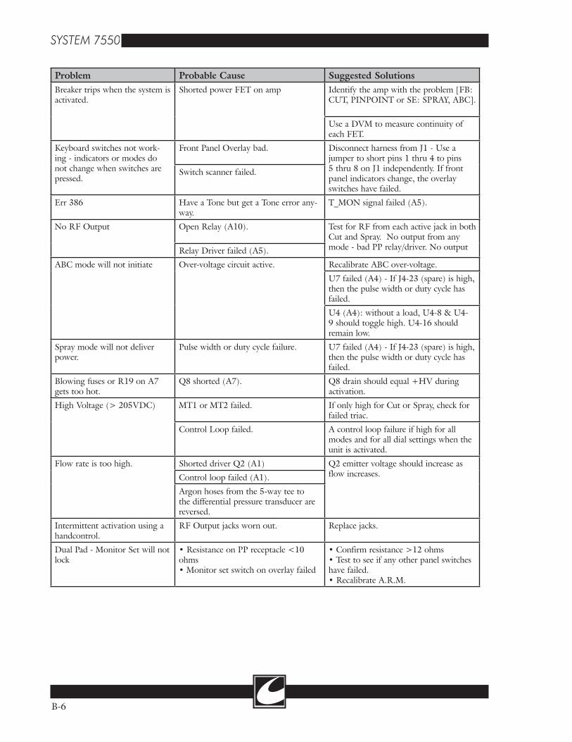
B-6
Problem Probable Cause Suggested SolutionsBreaker trips when the system is activated.
Shorted power FET on amp Identify the amp with the problem [FB: CUT, PINPOINT or SE: SPRAY, ABC].
Use a DVM to measure continuity of each FET.
Keyboard switches not work-ing - indicators or modes do not change when switches are pressed.
Front Panel Overlay bad. Disconnect harness from J1 - Use a jumper to short pins 1 thru 4 to pins 5 thru 8 on J1 independently. If front panel indicators change, the overlay switches have failed.
Switch scanner failed.
Err 386 Have a Tone but get a Tone error any-way.
T_MON signal failed (A5).
No RF Output Open Relay (A10). Test for RF from each active jack in both Cut and Spray. No output from any mode - bad PP relay/driver. No output Relay Driver failed (A5).
ABC mode will not initiate Over-voltage circuit active. Recalibrate ABC over-voltage.
U7 failed (A4) - If J4-23 (spare) is high, then the pulse width or duty cycle has failed.
U4 (A4): without a load, U4-8 & U4-9 should toggle high. U4-16 should remain low.
Spray mode will not deliver power.
Pulse width or duty cycle failure. U7 failed (A4) - If J4-23 (spare) is high, then the pulse width or duty cycle has failed.
Blowing fuses or R19 on A7 gets too hot.
Q8 shorted (A7). Q8 drain should equal +HV during activation.
High Voltage (> 205VDC) MT1 or MT2 failed. If only high for Cut or Spray, check for failed triac.
Control Loop failed. A control loop failure if high for all modes and for all dial settings when the unit is activated.
Flow rate is too high. Shorted driver Q2 (A1) Q2 emitter voltage should increase as flow increases.Control loop failed (A1).
Argon hoses from the 5-way tee to the differential pressure transducer are reversed.
Intermittent activation using a handcontrol.
RF Output jacks worn out. Replace jacks.
Dual Pad - Monitor Set will not lock
• Resistance on PP receptacle <10 ohms• Monitor set switch on overlay failed
• Confirm resistance >12 ohms• Test to see if any other panel switches have failed.• Recalibrate A.R.M.

B-7
No RF Output. No RF Drive on the Power FETs. If true for both amps, then: -HVDC < 12V -Check for 15V on T1 & T2 of the amplifiers. -PP relay (not the problem if bipolar or ABC have no RF output).
If only one amp, then: -Spray relays if only Spray (K2, K4) -FILR relay if Cut, Blend, Pinpoint and Bipolar (K1, K3) -PP relay if Cut, Blend, Pinpoint and Spray (K8) -ABC relay if only ABC (K9) -Bipolar relay(s) if only Bipolar (K10,11)
If only a handcontrol or footcontrol, then the relay associated with that RF output.
Error Storage and Retrieval
The last 16 activation errors are saved automati-cally. Power On Self Test, idle, and test mode errors are not stored. Activation errors are saved in a circular buffer that writes over the oldest error and saves the new error. If multiple error codes occur and are displayed during use of the unit, they are stored in the sequence that they are displayed.
• Unit must be in test mode to activate error display.
• Press “Store” switch to display errors or to exit error display.
• First error to be displayed will be the newest. BIPOLAR POWER DISPLAY will show 1.
• Use PROGRAM SELECT SWITCHES to display the other errors.
• Press “Monitor Set” switch to clear error memory.
Error Display Configuration
BIPOLAR POWER DISPLAY -Error number, 1 is the newest and 16 the oldest.
ABC POWER DISPLAY -Last active mode power setting.
GAS FLOW DISPLAY -Flow setting.
BLEND DISPLAY -Blend setting.
PROGRAM DISPLAY -Program setting.
MONOPOLAR CUT/BLEND POWER DISPLAY -Toggle between “Err” and the error code.
MONOPOLAR COAG POWER DISPLAY -Toggle between Active status and Mode LED status.
Mode LED status is displayed when the MONOPOLAR CUT/BLEND POWER DISPLAY shows “Err”.Note: the Active status and Mode LED status codes are in decimal and must be translated to binary. The individual bit field description can be obtained from lists shown below. D0 is the least significant bit and D7 is the most the least significant bit.Active status
D0 =1 when “Return Fault” LED on D1 =1 when FLOW FAULT ALARM LED on D2 =1 when LOW GAS SUPPLY LED on D3 =1 when Remote Power Control Mode active

B-8
D7 - D4 = ACTIVATION REQUEST 0000 = no request 0001 = Hand Control 1 Cut 0010 = Hand Control 2 Cut 0011 = Hand Control 1 Coag 0100 = Hand Control 2 Coag 0101 = Hand Control 1 Coag and Hand
Control 2 Coag 0110 = Foot Cut 0111 = Foot Coag 1000 = ABC 1001 = Bipolar 1010 = Hand Control 1 Coag and Foot Coag
1011 = Hand Control 2 Coag and Foot Coag 1100 = multiple keys not released 1101 to 1111 are not used
Mode LED status D0 =1 when “Remote” on D1 =1 when “Dual Pad” on D2 =1 when “Single Pad” on D3 =1 when “Manual” on D4 =1 when “Automatic” on D5 =1 when “Pin Point” on D6 =1 when “Spray” on D7 =1 when “Endo” on
Example Error
This example is for an error 301.• The MONOPOLAR CUT/BLEND POWER DISPLAY will toggle between “Err” and “301”.• The MONOPOLAR COAG POWER DISPLAY may toggle between “44” and “128”. The Mode LED
status “44” is displayed at the same time as “Err”.• To interpret the 44, convert from decimal to binary 00101100. From the Mode LED status list we can
see that “Single Pad”, “Manual”, and “Pin Point” LED’s were on at the time of the “Err”.• Convert 132 decimal to binary 10000100. From the Active status list we can see that the LOW GAS
SUPPLY LED was on and ABC was activated at the time of the “Err”.• The table below is an illustration of this example.
SYSTEM 7550CONTROL
PANELTRANSLATION
MO
NO
POL
AR
CU
T/B
LE
ND
PO
WE
R D
ISPL
AY
MO
NO
POL
AR
CO
AG
PO
WE
R D
ISPL
AY
MODE LED STATUS ACTIVE STATUS
“EN
DO
”
“SPR
AY
”
“PIN
PO
INT
”
“AU
TO
MA
TIC
”
“MA
NU
AL
”
“SIN
GL
E P
AD
”
“DU
AL
PA
D”
“RE
MO
TE
”
GO
TO
LIS
TD
7-D
4=A
CT
IVA
TIO
N R
EQ
UE
ST
RE
MO
TE
PO
WE
R C
ON
TR
OL
MO
DE
LO
W G
AS
SUPP
LY L
ED
LO
W F
AU
LT A
LA
RM
LE
D
“RE
TU
RN
FA
ULT
” L
ED
D7 D6 D5 D4
Err 44 0 0 1 0 1 1 0 0
301 132 1 0 0 0 0 1 0 0

Figu
re B
-1
Sig
nal S
tatu
s fo
r a
Han
dcon
trol
1, C
ut A
ctiv
atio
n R
eque
st
B-9
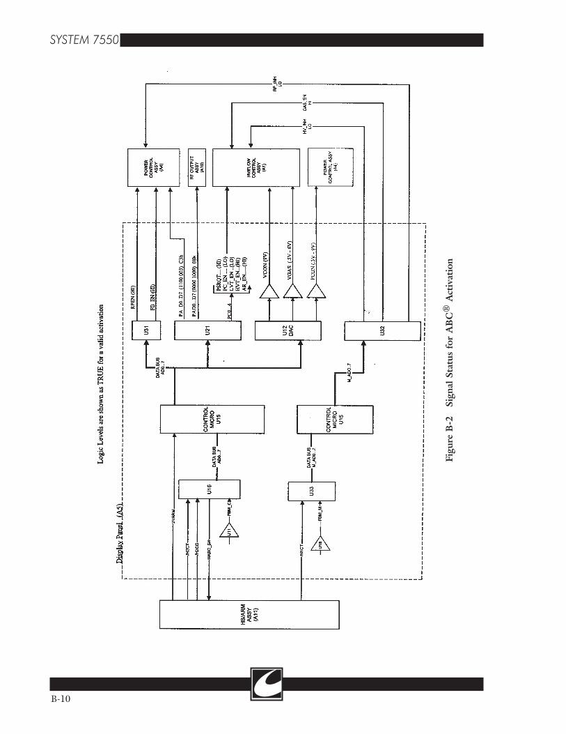
Figu
re B
-2
Sig
nal S
tatu
s fo
r A
BC
® A
ctiv
atio
n
B-10